WO2022176240A1 - 情報管理システム - Google Patents
情報管理システム Download PDFInfo
- Publication number
- WO2022176240A1 WO2022176240A1 PCT/JP2021/033001 JP2021033001W WO2022176240A1 WO 2022176240 A1 WO2022176240 A1 WO 2022176240A1 JP 2021033001 W JP2021033001 W JP 2021033001W WO 2022176240 A1 WO2022176240 A1 WO 2022176240A1
- Authority
- WO
- WIPO (PCT)
- Prior art keywords
- information
- unit
- vehicle
- driver
- management system
- Prior art date
- Legal status (The legal status is an assumption and is not a legal conclusion. Google has not performed a legal analysis and makes no representation as to the accuracy of the status listed.)
- Ceased
Links
Images





Classifications
-
- H—ELECTRICITY
- H04—ELECTRIC COMMUNICATION TECHNIQUE
- H04L—TRANSMISSION OF DIGITAL INFORMATION, e.g. TELEGRAPHIC COMMUNICATION
- H04L9/00—Cryptographic mechanisms or cryptographic arrangements for secret or secure communications; Network security protocols
- H04L9/50—Cryptographic mechanisms or cryptographic arrangements for secret or secure communications; Network security protocols using hash chains, e.g. blockchains or hash trees
-
- H—ELECTRICITY
- H04—ELECTRIC COMMUNICATION TECHNIQUE
- H04L—TRANSMISSION OF DIGITAL INFORMATION, e.g. TELEGRAPHIC COMMUNICATION
- H04L9/00—Cryptographic mechanisms or cryptographic arrangements for secret or secure communications; Network security protocols
- H04L9/32—Cryptographic mechanisms or cryptographic arrangements for secret or secure communications; Network security protocols including means for verifying the identity or authority of a user of the system or for message authentication, e.g. authorization, entity authentication, data integrity or data verification, non-repudiation, key authentication or verification of credentials
- H04L9/3226—Cryptographic mechanisms or cryptographic arrangements for secret or secure communications; Network security protocols including means for verifying the identity or authority of a user of the system or for message authentication, e.g. authorization, entity authentication, data integrity or data verification, non-repudiation, key authentication or verification of credentials using a predetermined code, e.g. password, passphrase or PIN
- H04L9/3231—Biological data, e.g. fingerprint, voice or retina
-
- G—PHYSICS
- G06—COMPUTING OR CALCULATING; COUNTING
- G06F—ELECTRIC DIGITAL DATA PROCESSING
- G06F21/00—Security arrangements for protecting computers, components thereof, programs or data against unauthorised activity
- G06F21/60—Protecting data
- G06F21/62—Protecting access to data via a platform, e.g. using keys or access control rules
- G06F21/6218—Protecting access to data via a platform, e.g. using keys or access control rules to a system of files or objects, e.g. local or distributed file system or database
- G06F21/6245—Protecting personal data, e.g. for financial or medical purposes
- G06F21/6254—Protecting personal data, e.g. for financial or medical purposes by anonymising data, e.g. decorrelating personal data from the owner's identification
-
- H—ELECTRICITY
- H04—ELECTRIC COMMUNICATION TECHNIQUE
- H04L—TRANSMISSION OF DIGITAL INFORMATION, e.g. TELEGRAPHIC COMMUNICATION
- H04L9/00—Cryptographic mechanisms or cryptographic arrangements for secret or secure communications; Network security protocols
- H04L9/08—Key distribution or management, e.g. generation, sharing or updating, of cryptographic keys or passwords
- H04L9/0894—Escrow, recovery or storing of secret information, e.g. secret key escrow or cryptographic key storage
- H04L9/0897—Escrow, recovery or storing of secret information, e.g. secret key escrow or cryptographic key storage involving additional devices, e.g. trusted platform module [TPM], smartcard or USB
-
- H—ELECTRICITY
- H04—ELECTRIC COMMUNICATION TECHNIQUE
- H04L—TRANSMISSION OF DIGITAL INFORMATION, e.g. TELEGRAPHIC COMMUNICATION
- H04L9/00—Cryptographic mechanisms or cryptographic arrangements for secret or secure communications; Network security protocols
- H04L9/30—Public key, i.e. encryption algorithm being computationally infeasible to invert or user's encryption keys not requiring secrecy
-
- H—ELECTRICITY
- H04—ELECTRIC COMMUNICATION TECHNIQUE
- H04L—TRANSMISSION OF DIGITAL INFORMATION, e.g. TELEGRAPHIC COMMUNICATION
- H04L9/00—Cryptographic mechanisms or cryptographic arrangements for secret or secure communications; Network security protocols
- H04L9/32—Cryptographic mechanisms or cryptographic arrangements for secret or secure communications; Network security protocols including means for verifying the identity or authority of a user of the system or for message authentication, e.g. authorization, entity authentication, data integrity or data verification, non-repudiation, key authentication or verification of credentials
- H04L9/3234—Cryptographic mechanisms or cryptographic arrangements for secret or secure communications; Network security protocols including means for verifying the identity or authority of a user of the system or for message authentication, e.g. authorization, entity authentication, data integrity or data verification, non-repudiation, key authentication or verification of credentials involving additional secure or trusted devices, e.g. TPM, smartcard, USB or software token
-
- H—ELECTRICITY
- H04—ELECTRIC COMMUNICATION TECHNIQUE
- H04L—TRANSMISSION OF DIGITAL INFORMATION, e.g. TELEGRAPHIC COMMUNICATION
- H04L9/00—Cryptographic mechanisms or cryptographic arrangements for secret or secure communications; Network security protocols
- H04L9/32—Cryptographic mechanisms or cryptographic arrangements for secret or secure communications; Network security protocols including means for verifying the identity or authority of a user of the system or for message authentication, e.g. authorization, entity authentication, data integrity or data verification, non-repudiation, key authentication or verification of credentials
- H04L9/3247—Cryptographic mechanisms or cryptographic arrangements for secret or secure communications; Network security protocols including means for verifying the identity or authority of a user of the system or for message authentication, e.g. authorization, entity authentication, data integrity or data verification, non-repudiation, key authentication or verification of credentials involving digital signatures
-
- G—PHYSICS
- G06—COMPUTING OR CALCULATING; COUNTING
- G06Q—INFORMATION AND COMMUNICATION TECHNOLOGY [ICT] SPECIALLY ADAPTED FOR ADMINISTRATIVE, COMMERCIAL, FINANCIAL, MANAGERIAL OR SUPERVISORY PURPOSES; SYSTEMS OR METHODS SPECIALLY ADAPTED FOR ADMINISTRATIVE, COMMERCIAL, FINANCIAL, MANAGERIAL OR SUPERVISORY PURPOSES, NOT OTHERWISE PROVIDED FOR
- G06Q40/00—Finance; Insurance; Tax strategies; Processing of corporate or income taxes
- G06Q40/08—Insurance
-
- H—ELECTRICITY
- H04—ELECTRIC COMMUNICATION TECHNIQUE
- H04L—TRANSMISSION OF DIGITAL INFORMATION, e.g. TELEGRAPHIC COMMUNICATION
- H04L2209/00—Additional information or applications relating to cryptographic mechanisms or cryptographic arrangements for secret or secure communication H04L9/00
- H04L2209/84—Vehicles
Definitions
- the present disclosure relates to an information management system that manages information regarding vehicle drivers.
- a data collection system that includes an in-vehicle device mounted on a vehicle and a server that communicates with the in-vehicle device via a network and collects probe data from the vehicle is known (Patent Document 1, abstract, Claim 1, etc.).
- the server includes a data collection condition determination unit, a data collection condition distribution unit, and a probe reception processing unit.
- the in-vehicle device includes a data acquisition unit, a collection data narrowing processing unit, and a probe data transmission unit.
- the data collection condition determination unit of the server determines data collection conditions including the frequency of probe data collection in the vehicle. Further, the data collection condition distribution unit of the server distributes the data collection conditions determined by the data collection condition determination unit to the vehicle. Further, the probe reception processing unit of the server receives probe data transmitted from the vehicle and stores it in the storage device.
- the data acquisition unit of the in-vehicle device acquires data related to the surrounding environment or state of the vehicle. Further, the collected data narrowing processing unit of the in-vehicle device extracts probe data from the data acquired by the data acquisition unit for each collection frequency based on the data collection conditions distributed from the server. Further, the probe data transmission unit of the in-vehicle device transmits the probe data extracted for each collection frequency by the collection data narrowing processing unit to the server.
- the data acquired by the vehicle can be collected by the server at an appropriate data collection frequency (Patent Document 1, paragraph 0008, etc.).
- Patent Document 1 paragraph 0008, etc.
- this conventional data collection system has a problem regarding the handling of information related to each driver when a single vehicle is driven by a plurality of drivers, such as in car sharing.
- the present disclosure provides an information management system capable of solving the problem of handling information related to each driver when multiple drivers drive one vehicle.
- One aspect of the present disclosure is an information management system that manages driver information about a driver of a vehicle, comprising: a driver identification unit that acquires personal identification information of the driver; An information management system comprising: an information acquisition unit that acquires driver information; and an individual information storage unit that stores individual information in which the individual identification information and the driver information are associated.
- an information management system capable of solving problems related to the handling of information relating to each driver when a single vehicle is driven by a plurality of drivers. can be done.
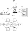
- FIG. 1 is a block diagram showing Embodiment 1 of an information management system according to the present disclosure
- FIG. 1 is a block diagram of a vehicle equipped with an information management system according to Embodiment 1
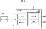
- FIG. 3 is a block diagram showing an example of an electronic key that wirelessly communicates with the key input unit shown in FIG. 2
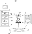
- FIG. 3 is a block diagram showing an example of a PDA that wirelessly communicates with the key input unit in FIG. 2
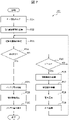
- FIG. 3 is a flowchart showing an example of processing by the information management system of FIG. 2
- FIG. 2 is a block diagram of a vehicle equipped with an information management system according to a second embodiment
- FIG. FIG. 7 is a flowchart showing an example of processing by the information management system of FIG. 6
- FIG. 7 is a flowchart showing an example of processing by the information management system of FIG. 6;
- FIG. 7 is a flowchart showing an example of processing by the information management system of FIG. 6;
- FIG. 11 is a block diagram of a driver identification unit of an information management system according to Embodiment 3;
- FIG. 11 is a flowchart showing an example of processing by the information management system according to the third embodiment;
- FIG. 1 is a block diagram showing Embodiment 1 of an information management system according to the present disclosure.
- FIG. 2 is a block diagram of a vehicle V equipped with the information management system 1 according to the first embodiment.
- the information management system 1 of the present embodiment is a system that manages driver information about the driver of the vehicle V, and is a vehicle system mounted on the vehicle V, for example.
- Vehicle V is, for example, a gasoline engine vehicle, a diesel engine vehicle, a hybrid vehicle, an electric vehicle, or a hydrogen vehicle.
- the vehicle V communicates with a server S in a data center DC and a plurality of computers forming a distributed network DN via, for example, a wireless communication line RCL, a wireless base station WBS, and a wired communication line WCL. Connected to PC.
- a plurality of computers PC forming a distributed network DN perform data communication in a P2P (peer-to-peer) network system.
- P2P peer-to-peer
- the information management system 1 includes, for example, a key authentication section 11 including a driver identification section 111, an information acquisition section 12, and an information management section 13, as shown in FIG.
- the information management system 1 may also include, for example, a key input unit 14 mounted on the vehicle V, a communication unit 15 , a plurality of electronic control units (ECUs) 16 and 17 , and an in-vehicle network 18 .
- the information management system 1 may also include devices and networks external to the vehicle V, such as the server S of the data center DC shown in FIG. 1 and the computer PC that configures the distributed network DN.
- the communication unit 15 includes, for example, a wireless communication device capable of communicating with a wireless base station WBS and a communication device outside the vehicle V via a wireless communication line RCL.
- the ECUs 16 and 17 are, for example, electronic control units for controlling the powertrain of the vehicle V, various actuators that constitute an advanced driver assistance system (ADAS), and an automatic driving system (ADS).
- the in-vehicle network 18 is configured by, for example, a controller area network (CAN), Ethernet (registered trademark), or the like. Illustrations and descriptions of other general configurations of the vehicle V are omitted.
- the key input unit 14 performs wireless communication with, for example, an electronic key that constitutes the keyless entry system of the vehicle V, a smart key that constitutes the smart entry system of the vehicle V, or a mobile information terminal. As a result, the key input unit 14 acquires encrypted information including the vehicle identification number VIN from the electronic key, smart key, or personal digital assistant. Also, the encrypted information acquired by the key input unit 14 includes, for example, personal identification information PI. Personal identification information PI includes, for example, a personal identification number PIN. Key input unit 14 outputs encrypted information acquired from an electronic key, a smart key, or a portable information terminal to key authentication unit 11, for example.
- FIG. 3 is a block diagram showing an example of the electronic key 2 that wirelessly communicates with the key input unit 14 of FIG.
- the information management system 1 may include an electronic key 2, for example.
- the electronic key 2 includes, for example, an antenna 21, a microcontroller 22, and an operation button 23.
- the antenna 21 performs wireless communication with the key input unit 14, for example.
- the microcontroller 22 includes, for example, a nonvolatile memory 221 and an input/output unit 222.
- Memory 221 stores, for example, encrypted vehicle identification number VIN and encrypted personal identification information PI.
- the input/output unit 222 reads out the encrypted vehicle identification number VIN and the personal identification information PI from the memory 221 and transmits them to the key input unit 14 via the antenna 21 .
- the input/output unit 222 reads out the encrypted vehicle identification number VIN and personal identification information PI from the memory 221 . Further, input/output unit 222 transmits the encrypted vehicle identification number VIN and personal identification information PI together with the response code to key input unit 14 via antenna 21 .
- FIG. 4 is a block diagram showing an example of the portable information terminal 3 that wirelessly communicates with the key input unit 14 of FIG.
- the mobile information terminal 3 is abbreviated as "PDA3".
- Information management system 1 may include PDA 3, for example.
- PDA 3 is, for example, a smart phone or tablet computer.
- the PDA 3 comprises, for example, a communication section 31, a microcontroller 32, and an input section 33.
- the communication unit 31 of the PDA 3 performs wireless communication with the key input unit 14 mounted on the vehicle V, for example, by short-range wireless communication such as Bluetooth (registered trademark). Note that the short-range wireless communication protocol is not limited to Bluetooth (registered trademark). Further, the communication unit 31 communicates with the server S installed in the data center DC outside the vehicle V via, for example, the wireless communication line RCL, the wireless base station WBS, and the communication network CN.
- short-range wireless communication such as Bluetooth (registered trademark).
- the short-range wireless communication protocol is not limited to Bluetooth (registered trademark).
- the communication unit 31 communicates with the server S installed in the data center DC outside the vehicle V via, for example, the wireless communication line RCL, the wireless base station WBS, and the communication network CN.
- the server S of the data center DC includes, for example, key management software S1 and a user database S2.
- Personal identification information PI and vehicle identification number VIN are registered in user database S2 in association with the user ID of the driver of vehicle V, for example.
- the microcontroller 32 of the PDA3 comprises, for example, a key management application 321 and a memory 322.
- the key management application 321 is, for example, a program stored in the memory of the microcontroller 32 and executed by the central processing unit (CPU) of the microcontroller 32 .
- the key management application 321 transmits, for example, the user ID input by the driver of the vehicle V through the input unit 33 to the server S of the data center DC through the communication unit 31 .
- the key management software S1 of the server S of the data center DC is stored in the storage device of the server S and executed by the CPU of the server S.
- the key management software S1 receives the user ID of the driver of the vehicle V transmitted from the PDA3 via the radio base station WBS and the communication network CN. Then, the key management software S1 reads the vehicle identification number VIN and personal identification information PI corresponding to the received user ID from the user database S2 and encrypts them. Further, the key management software S1 transmits the encrypted vehicle identification number VIN and personal identification information PI to the PDA3 via the communication network CN and the radio base station WBS.
- the key management application 321 of the PDA 3 receives the encrypted vehicle identification number VIN and personal identification information PI via the communication unit 31 and stores them in the memory 322. Furthermore, the key management application 321 transmits the encrypted vehicle identification number VIN and personal identification information PI to the key input unit 14 via the communication unit 31 of the PDA3.
- the key management application 321 of the PDA3 may be installed on the server S of the data center DC.
- the microcontroller 32 of the PDA 3 receives an execution file for transmission of the encrypted vehicle identification number VIN and personal identification information PI, for example, from the server S of the data center DC, and stores it in the memory 322 . This makes it possible to omit the key management application 321 of the PDA3.
- the key authentication unit 11 is, for example, a microcontroller or ECU including a CPU, memory, timer, and input/output unit.
- the key authentication unit 11 receives the information output from the key input unit 14 and authenticates and identifies the vehicle V and the driver.
- Key authentication unit 11 includes, for example, driver identification unit 111 , VIN storage unit 112 , VIN comparison unit 113 , and interface unit 114 .
- Each unit of these key authentication units 11 may represent functions of the key authentication unit 11 that are realized by executing programs stored in the memory by the CPU, for example.
- the driver identification unit 111 decrypts and decrypts the encrypted information that is the output of the key input unit 14.
- the driver identification unit 111 further extracts personal identification information PI including the personal identification number PIN from the plaintext information and separates the vehicle identification number VIN.
- Driver identification unit 111 outputs vehicle identification number VIN separated from the plaintext information to VIN comparison unit 113 .
- the driver identification unit 111 outputs the personal identification information PI including the personal identification number PIN extracted from the plaintext information to the information acquisition unit 12 and the information management unit 13 via the interface unit 114 and the in-vehicle network 18. do.
- the VIN storage unit 112 is configured by a memory, for example, and stores the vehicle identification number VIN unique to the vehicle V.
- VIN comparison unit 113 compares, for example, vehicle identification number VIN input from driver identification unit 111 and vehicle identification number VIN stored in VIN storage unit 112 . When these vehicle identification numbers VIN match, the VIN comparison unit 113 transmits the comparison result to a vehicle driving ECU (not shown) via the interface unit 114 and the in-vehicle network 18 . This makes it possible to drive the power source such as the engine and the motor of the vehicle V to make the vehicle V run.
- the key authentication unit 11 decrypts the information including the encrypted vehicle identification number VIN and the personal identification information PI output from the key input unit 14 by the driver identification unit 111 and converts it into plain text. do. As a result, the key authentication unit 11 acquires the vehicle identification number VIN of the vehicle V and the personal identification information PI of the driver of the vehicle V, and authenticates and identifies the vehicle V and the driver of the vehicle V.
- FIG. 1 A block diagram Identifier
- the information acquisition unit 12 is, for example, a microcontroller or ECU including a CPU, memory, timer, and input/output unit.
- the information acquisition unit 12 acquires driver information DI including travel information TI of the vehicle V.
- the information acquisition unit 12 includes an interface unit 121, a PI storage unit 122, a condition setting unit 123, a DI collection unit 124, and an individual information storage unit 125, for example.
- the individual information storage unit 125 may be abbreviated as “PD storage unit 125”.
- Each unit of the information acquisition unit 12 may represent a function of the information acquisition unit 12 that is realized by, for example, executing a program stored in the memory by the CPU.
- the interface unit 121 transmits and receives data to and from the key authentication unit 11, the information management unit 13, and the communication unit 15 via the in-vehicle network 18, for example.
- the PI storage unit 122 temporarily stores the personal identification information PI input from the key authentication unit 11 via the interface unit 114 , the in-vehicle network 18 and the interface unit 121 .
- the condition setting unit 123 sets conditions such as the type, frequency and format of the driver information DI collected by the DI collection unit 124 .
- the DI collection unit 124 collects driver information DI via the interface unit 121 and the in-vehicle network 18 according to the conditions set by the condition setting unit 123 .
- the driver information DI includes at least travel information TI of the vehicle V.
- the PD storage unit 125 stores the driver information DI collected by the DI collection unit 124 and the personal identification information PI of the driver of the vehicle V stored in the PI storage unit 122. is stored as individual information PD associated with.
- the travel information TI of the vehicle V includes the driving tendency DT of the driver of the vehicle V, for example.
- the driver's driving tendency DT includes, for example, the number of times items shown in Table 1 are recorded for each day. Note that the item of the driver's driving tendency DT shown in Table 1 is an example, and is not particularly limited.
- the individual information PD including the driving tendency DT of the driver of the vehicle V as shown in Table 1 can be applied, for example, to the calculation of insurance premiums in telematics insurance.
- the server S installed in the data center DC outside the vehicle V shown in FIG. 1 can include, for example, insurance premium calculation software S3 and an insurance premium calculation database S4. Calculation of insurance premiums by the server S of the data center DC will be described later.
- the travel information TI of the vehicle V may include information such as the position, travel route, speed, acceleration, and angular velocity of the vehicle V in addition to the driving tendency DT of the driver.
- the driver information DI includes, in addition to the traveling information TI of the vehicle V, setting of the vehicle V for each driver such as the position and angle of the seat, the position and angle of the mirror, lighting, and air conditioning, and in-vehicle information. Preferences related to tainment may also be included.
- the information acquisition unit 12 acquires the driver information DI including the travel information TI of the vehicle V by the DI collection unit 124, for example. Furthermore, the information acquisition unit 12 outputs the individual information PD stored in the PD storage unit 125 to the information management unit 13 via the interface unit 121 and the in-vehicle network 18, for example, as required.
- the information management unit 13 is, for example, a microcontroller or ECU including a CPU, memory, timer, and input/output unit.
- the information management unit 13 manages the individual information PD that associates the personal identification information PI and the driver information DI as described above.
- the information management unit 13 includes, for example, an interface unit 131, an individual information storage unit 132, a private key storage unit 133, an address calculation unit 134, an electronic signature unit 135, and a public key generation unit 136. .
- Each section of the information management section 13 may represent, for example, the function of the information management section 13 realized by executing a program stored in the memory by the CPU. Further, hereinafter, the individual information storage unit 132 may be abbreviated as “PD storage unit 132”.
- the interface unit 131 transmits and receives data to and from the information acquisition unit 12 and the communication unit 15 via the in-vehicle network 18, for example.
- the PD storage unit 132 is configured by a memory, for example, and acquires and stores the individual information PD stored in the PD storage unit 125 of the information acquisition unit 12 via the interface unit 131 and the in-vehicle network 18 . If the information acquisition unit 12 does not have the PD storage unit 125, the PD storage unit 132 of the information management unit 13 associates the personal identification information PI and the driver information DI individually acquired from the information acquisition unit 12, It may be stored as individual information PD as shown in Table 1 above.
- the secret key storage unit 133 is composed of, for example, a non-volatile memory such as a ROM, and stores a plurality of personal identification information PIs and a plurality of secret keys SK in one-to-one correspondence. That is, the private key storage unit 133 stores one private key SK at one address in association with one piece of personal identification information PI.
- individual information PD is created from the personal identification information PI acquired by the key input unit 14 and the driver information DI acquired by the information acquisition unit 12 . The individual information PD may be created by associating the identification information PI and the driver information DI.
- Writing the private key SK to the private key storage unit 133 can be performed, for example, as follows.
- the seed that is the source of the secret key SK is written in the non-volatile memory
- the secret key encryption calculation software is installed in the information management unit 13
- the seed is input to create the secret key SK
- the secret key SK is created in the non-volatile memory.
- the secret key cipher calculation software may be downloaded before writing the seed at the production plant and deleted after the secret key SK is created.
- the address calculation unit 134 receives, for example, the personal identification information PI included in the individual information PD stored in the PD storage unit 132, and the private key storage unit 133 stores the secret key SK corresponding to the personal identification information PI. output the address of
- the electronic signature unit 135 refers to the address of the private key storage unit 133 output from the address calculation unit 134 to acquire the private key SK and acquires the individual information PD from the PD storage unit 132 .
- the individual information PD is, for example, information in which personal identification information PI is added to the head of driver information DI.
- the electronic signature unit 135 calculates a hash value of the individual information PD acquired from the PD storage unit 132 using, for example, a hash function.
- the electronic signature unit 135 encrypts the calculated hash value using the secret key SK obtained from the secret key storage unit 133 .
- the electronic signature unit 135 can create an electronic signature based on the RSA cryptosystem.
- the public key generation unit 136 obtains the secret key SK by referring to the address of the secret key storage unit 133 output from the address calculation unit 134, for example, and generates the public key PK using the obtained secret key SK. .
- Each public key PK corresponding to the private key SK specific to each driver stored in the private key storage unit 133 is transmitted to each driver via the interface unit 131, the in-vehicle network 18, and the communication unit 15. It may be transmitted in advance to the transmission destination of the individual information PD of the person.
- the information management unit 13 transmits the individual information PD to which the electronic signature is attached by the electronic signature unit 135 to the outside of the vehicle V via the interface unit 131, the in-vehicle network 18, and the communication unit 15.
- the electronically signed individual information PD transmitted from the vehicle V is transmitted to the radio base station WBS via the radio communication line RCL, for example, as shown in FIG.
- the electronically signed individual information PD received by the wireless base station WBS is transmitted to the server S of the data center DC and the computer PC constituting the distributed network DN, for example, via the wired communication line WCL.
- the server S and the computer PC for example, authenticate individual information PD with an electronic signature received from the information management section 13 of the information management system 1 with the public key PK generated by the same information management section 13 .
- the computer PC or its user may, for example, register the authenticated individual information PD in the blockchain.
- the electronic signature unit 135 encrypts the hash value of the block of the previous individual information PD with the secret key SK when transmitting the block of the new individual information PD. , creates an electronic signature for the block of new individual information PD. This allows the computer PC or its user to authenticate the electronically signed individual information PD with the public key PK and register it in the blockchain.
- the information management unit 13 obtains information that does not require an electronic signature from the driver information DI acquired by the information acquisition unit 12 , via the interface unit 131 , the in-vehicle network 18 , and the communication unit 15 . without creating an electronic signature outside of the Further, the electronic signature unit 135 may encrypt information including the individual information PD to be transmitted to the outside of the vehicle V with the secret key SK.
- an information management system 1 of this embodiment is connected to, for example, a distributed network DN and a data center DC, so that a vehicle V and the data center DC bidirectionally transmit and receive data and programs. ing.
- Examples of sending data and programs from the data center DC to the vehicle V include FOTA (Firmware Over-The-Air) for updating the ECU program, updating map data for the car navigation system, and distributing music data.
- FOTA Firmware Over-The-Air
- Examples of sending data and programs from the data center DC to the vehicle V include FOTA (Firmware Over-The-Air) for updating the ECU program, updating map data for the car navigation system, and distributing music data.
- FOTA Firmware Over-The-Air
- the data center DC can manage the parts of the vehicle V, for example, by transmitting the diagnostic information of the parts received from the vehicle V to the car dealer, and the car dealer can replace the parts.
- Telematics insurance which reflects driving information TI of vehicle V in insurance premiums, is based on the driver's driving tendency DT, such as the driver's sudden braking and acceleration, from the stage of calculating the insurance premium based on the mileage of vehicle V. are moving to the stage of calculating insurance premiums.
- DT driving tendency
- telematics insurance for example, when multiple residents of a large-scale housing complex share a vehicle V, when multiple drivers share a vehicle, insurance premiums must be set for each driver. is reasonable.
- travel information TI of the vehicle V is collected for each driver, and the collected travel information TI is used. It is necessary to manage it in a state that can be identified by the driver. Further, the vehicle V is required to transmit travel information TI including the driving tendency DT of the driver to the external data center DC in a state in which the driver can be identified. Furthermore, if the travel information TI for each driver is managed by a distributed ledger such as a blockchain, it is required to support registration in the blockchain.
- FIG. 5 is a flowchart showing an example of the flow of processing P1 by the information management system 1.
- the key input unit 14 mounted on the vehicle V communicates with the electronic key 2 or PDA 3 possessed by the driver. Thereby, the key input unit 14 receives the encrypted vehicle identification number VIN and the encrypted personal identification information PI from the electronic key 2 or the PDA 3 .
- the information management system 1 starts the process P1 shown in FIG. 5 and executes the key information input process P11.
- the driver identification unit 111 acquires the encrypted vehicle identification number VIN and the encrypted personal identification information PI of the driver from the key input unit .
- the driver identification unit 111 decrypts the vehicle identification number VIN and the personal identification information PI, and separates the vehicle identification number VIN and the personal identification information PI to separate the vehicle identification number VIN and the personal identification information PI.
- a number VIN and personal identification information PI are obtained respectively.
- the VIN comparison unit 113 compares the vehicle identification number VIN acquired from the key input unit 14 and the vehicle identification number VIN stored in the VIN storage unit 112, and if they do not match, the vehicle V is not started. . In this case, the information management system 1 terminates the processing shown in FIG. Here, it is assumed that the vehicle identification number VIN acquired from the key input unit 14 and the vehicle identification number VIN stored in the VIN storage unit 112 match. Next, the information management system 1 executes, for example, a transmission process P12 of the personal identification information PI. In this process P12, the key authentication unit 11 transmits the personal identification information PI via the in-vehicle network 18, for example.
- the information management system 1 executes, for example, the driver information DI acquisition process P13.
- the information acquisition unit 12 receives the personal identification information PI via the in-vehicle network 18, for example, and causes the PI storage unit 122 to store the information. Furthermore, the information acquisition unit 12 collects the driver information DI by the DI collection unit 124 according to the conditions set by the condition setting unit 123 . Then, the information acquisition unit 12 causes the PD storage unit 125 to store the individual information PD that associates the personal identification information PI and the driver information DI.
- the information management system 1 executes, for example, transmission processing P14 of the individual information PD.
- the information acquisition unit 12 transmits the individual information PD via the in-vehicle network 18, for example.
- the information management system 1 executes a preparation process P15 for the secret key SK.
- the information management unit 13 receives the individual information PD via the in-vehicle network 18 by using the interface unit 131, for example, and causes the PD storage unit 132 to store the information. Further, the information management unit 13, for example, uses the address calculation unit 134 to calculate the address of the secret key storage unit 133 in which the secret key SK corresponding to the personal identification information PI included in the individual information PD is stored, and Output to signature unit 135 .
- the information management system 1 executes electronic signature processing P16, for example.
- the information management unit 13 uses the electronic signature unit 135 to refer to the address of the secret key storage unit 133 input from the address calculation unit 134, and obtains the personal identification information of the current driver of the vehicle V. Obtain the secret key SK corresponding to PI.
- the electronic signature unit 135 acquires the individual information PD from the PD storage unit 132.
- the electronic signature unit 135 electronically signs the individual information PD using the obtained secret key SK.
- the electronic signature may be applied after the individual information PD is encrypted.
- the information management system 1 executes the external transmission process P17, for example.
- the information management unit 13 transmits the electronically signed individual information PD to the outside of the vehicle V via the interface unit 131, the in-vehicle network 18, and the communication unit 15, for example.
- the process P1 of the information management system 1 shown in FIG. 5 is completed.
- the electronically signed individual information PD transmitted from the vehicle V is sent, for example, to the server S of the data center DC or the distributed Received by computer PC in network DN.
- the server S of the data center DC authenticates the received individual information PD with electronic signature by using the insurance premium calculation software S3, for example, using the public key PK corresponding to the personal identification information PI included in the individual information PD.
- the insurance premium calculation software S3 of the server S registers the individual information PD in the insurance premium calculation database S4.
- the individual information PD is information in which the personal identification information PI of each driver of the vehicle V and the driver information DI are associated with each other, as shown in Table 1 above.
- the driver information DI includes travel information TI of the vehicle V driven by each driver, and the travel information TI includes the driving tendency DT of each driver.
- the insurance premium calculation software S3 can appropriately calculate the risk for each driver based on the individual information PD for each driver registered in the insurance premium calculation database S4. fee can be calculated. This makes it possible to apply telematics insurance to each driver even when an unspecified number of drivers drive one vehicle V, such as in car sharing.
- the computer PC that constitutes the distributed network DN uses, for example, the public key PK corresponding to the personal identification information PI included in the individual information PD to authenticate the received individual information PD with an electronic signature, and block Register on the chain. This makes it possible to prevent falsification of the individual information PD and construct a highly reliable database using a distributed ledger.
- the information management system 1 of this embodiment is a system that manages the driver information DI regarding the driver of the vehicle V.
- the information management system 1 includes a driver identification unit 111 that obtains personal identification information PI of the driver of the vehicle V, an information acquisition unit 12 that obtains driver information DI including travel information TI of the vehicle V, and personal identification information and individual information storage units 125 and 132 that store individual information PD that associates PI with driver information DI.
- the information management system 1 of the present embodiment can identify individual drivers based on the personal identification information PI even when a plurality of drivers share one vehicle V, for example. , it becomes possible to collect the driver information DI including the travel information TI.
- the information management system 1 of this embodiment includes a communication unit 15 capable of communicating with the outside of the vehicle V, a secret key storage unit 133 storing a secret key SK unique to each personal identification information PI, and individual information PD and an electronic signature unit 135 for applying an electronic signature to the individual information PD using a private key SK specific to the personal identification information PI associated with . Further, the communication unit 15 transmits the individual information PD to which the electronic signature is attached to the outside of the vehicle V.
- a communication unit 15 capable of communicating with the outside of the vehicle V
- a secret key storage unit 133 storing a secret key SK unique to each personal identification information PI
- individual information PD and an electronic signature unit 135 for applying an electronic signature to the individual information PD using a private key SK specific to the personal identification information PI associated with .
- the communication unit 15 transmits the individual information PD to which the electronic signature is attached to the outside of the vehicle V.
- the information management system 1 of the present embodiment prevents spoofing by others, even when a plurality of drivers share one vehicle V, and the individual information PD can be used to identify individual drivers. It is possible to guarantee that it belongs to the person himself/herself.
- falsification of the individual information PD can be prevented when the individual information PD is transmitted and received between the vehicle V, the data center DC, the distributed network DN, and the like, and the individual information PD can be transmitted and received in a secure environment. can do.
- the driver identification unit 111 acquires personal identification information PI transmitted from the electronic key 2 of the vehicle V or the portable information terminal 3 owned by the driver. With such a configuration, even when a plurality of drivers use one vehicle V, it is possible to easily identify the drivers.
- the information management system 1 of this embodiment further includes a public key generation unit 136 that generates a public key PK corresponding to the private key SK unique to each piece of personal identification information PI.
- the communication unit 15 transmits the public key PK to the outside.
- the information management system 1 for example, transmits the public key PK to a plurality of computers PC constituting the distributed network DN, and further transmits individual information PD with an electronic signature created by the private key SK. can do. Therefore, it becomes possible to register individual information PD in a blockchain, which is a distributed ledger based on public key cryptography.
- the information management system 1 of the present embodiment when a plurality of drivers drive one vehicle V, the driver information DI including the travel information TI of each driver is independently stored. can be collected and output as Further, according to the information management system 1 of the present embodiment, it is possible to ensure security regarding the identification of individual drivers. That is, according to this embodiment, when a plurality of drivers drive one vehicle V, the information management system 1 is provided that can solve the problem of handling information related to each driver. be able to.
- FIG. 6 is a block diagram of a vehicle V equipped with the information management system 1 according to the second embodiment.
- the information management system 1 mainly differs from the information management system 1 of the first embodiment described above in that it includes a hardware security module 137 including a private key storage unit 133 and an electronic signature unit 135 .
- the hardware security module may be abbreviated as "HSM”.
- the key authentication unit 11, the information acquisition unit 12, the communication unit 15, and the ECUs 16 and 17 are configured by HSMs, respectively. It differs from the information management system 1 or the vehicle V of the first embodiment described above in that it includes 162 and 172 .
- the information management system 1 or the vehicle V of this embodiment also includes, for example, a battery power supply unit 19 . Since other configurations of the information management system 1 and the vehicle V of the present embodiment are the same as those of the information management system 1 and the vehicle V of the first embodiment, the same parts are denoted by the same reference numerals and explanations are given. omitted.
- the HSM 137 of the information management unit 13 includes a private key storage unit 133, an address calculation unit 134, an electronic signature unit 135, and a public key generation unit 136 similar to those in the first embodiment.
- the HSM 137 has, for example, a one-chip configuration in which all encryption processing is performed in one chip, an integrated configuration that is difficult to disassemble, hardware equipped with a true random number generation function, a secret key SK, a public To securely store electronic keys such as key PK and common key CK.
- the information management system 1 of the present embodiment includes the hardware security module 137 including the private key storage unit 133 and the electronic signature unit 135.
- the secret key SK unique to each driver is securely stored in the secret key storage unit 133 included in the HSM 137, Leakage of the secret key SK can be prevented more reliably. Therefore, according to the information management system 1 of this embodiment, it is possible not only to obtain the same effects as those of the above-described first embodiment, but also to ensure security in identifying the driver.
- the HSM 137 further includes an authentication unit 138.
- the authentication unit 138 stores, for example, a common key CK used for message authentication. That is, the HSM 137 can perform not only the electronic signature by the private key storage unit 133, the address calculation unit 134, the electronic signature unit 135, and the public key generation unit 136, but also the message authentication by the authentication unit 138.
- the HSM 137 can, for example, select either to electronically sign the data or to perform message authentication on the data according to instructions input with the data.
- Key authentication unit 11, information acquisition unit 12, communication unit 15, and authentication units 115, 126, 152, 162, and 172 of ECUs 16 and 17 are configured by hardware security modules like HSM 137 of information management unit 13. ing. Moreover, these authentication units 115 , 126 , 152 , 162 and 172 have the same configuration as the authentication unit 138 of the HSM 137 . However, unlike the HSM 137, these authentication units 115, 126, 152, 162, and 172 do not have the private key storage unit 133, the address calculation unit 134, the electronic signature unit 135, and the public key generation unit 136.
- Each authentication unit 115, 126, 138, 152, 162, 172 calculates the MAC value using a hash function based on the data to be transmitted to the in-vehicle network 18 and the common key CK. Further, each of the authentication units 115, 126, 138, 152, 162, and 172 receives data and a MAC value from the in-vehicle network 18, calculates the MAC value based on the received data and the common key CK, and calculates the calculated MAC value. Compare the value with the received MAC value. Then, if the calculated MAC value and the received MAC value match, the authentication is successful. This prevents falsification of data transmitted and received via the in-vehicle network 18, and enables secure communication between the key authentication unit 11, the information acquisition unit 12, the information management unit 13, the communication unit 15, and the ECUs 16 and 17. It becomes possible to do
- the battery power supply unit 19 is configured by, for example, a microcontroller or an ECU, and supplies power from a battery mounted on the vehicle V to the information acquisition unit 12 and the information management unit 13 when the activation switch of the vehicle V is turned off. Controls power supply and shutdown.
- the information management system 1 of this embodiment is similar to that of the first embodiment described above in that the individual information PD stored in the individual information storage units 125 and 132 is erased when the activation switch of the vehicle V is turned on or off. is different from the information management system 1 of Processing by the information management system 1 of this embodiment will be described below.
- FIG. 7 is a flowchart showing an example of processing P2 by the information management system 1 of this embodiment.
- the information management system 1 starts the process P2 shown in FIG. 7, the key information input process P11, the personal identification information PI transmission process P12, and the driver information DI acquisition process P13 of the first embodiment shown in FIG. Similar processes P21, P22 and P23 are executed.
- the information management system 1 executes, for example, the process P24 of determining whether or not the activation switch of the vehicle V is off by the battery power supply unit 19 .
- the information management system 1 determines whether the start switch of the vehicle V is turned on or when the previous external transmission process P29 ends. Then, a determination process P25 is executed to determine whether or not the predetermined time ts has elapsed. If it is determined in this process P25 that the predetermined time ts has not elapsed (NO), the information management system 1 executes the driver information DI acquisition process P23 again.
- the information management system 1 performs the transmission process P14 of the individual information PD and the secret key SK preparation process of the first embodiment shown in FIG. Processes P26, P27, P28, and P29 similar to P15, electronic signature process P16, and external transmission process P17 are executed. As a result, the individual information PD is periodically transmitted to the outside of the vehicle V until the start switch of the vehicle V is turned off.
- the information management system 1 causes the battery power supply unit 19, for example, to acquire information from the battery of the vehicle V. 12 and the information management unit 13 are supplied with power P2A.
- the information management system 1 executes, for example, the process P2B of deleting the individual information PD stored in the PD storage sections 125 and 132 by the information acquisition section 12 and the information management section 13 . Thereafter, the information management system 1, for example, causes the battery power supply unit 19 to execute processing P2C for stopping the supply of power from the battery of the vehicle to the information acquisition unit 12 and the information management unit 13, and the processing shown in FIG. End P2.
- the information management system 1 erases the individual information PD stored in the individual information storage units 125 and 132 when the activation switch of the vehicle V is turned off.
- the privacy of each driver can be protected by preventing the individual information PD of each driver from being known to other drivers. can.
- FIG. 8 is a flowchart showing an example of another process P3 by the information management system 1 of this embodiment.
- the information management system 1 starts the process P3 shown in FIG. 8, the key information input process P11, the personal identification information PI transmission process P12, and the driver information DI acquisition process P13 of the first embodiment shown in FIG. Similar processes P31, P32 and P33 are executed.
- the information management system 1 executes, for example, the process P34 of determining whether or not the activation switch of the vehicle V is off by the battery power supply unit 19 .
- the information management system 1 executes the driver information DI acquisition process P33 again.
- the information management system 1 for example, uses the battery power supply unit 19 to supply the information acquisition unit 12 and the A process P35 of supplying power to the information management unit 13 is executed.
- the information management system 1 performs processes P36 and P37 similar to the transmission process P14 of the individual information PD, the preparation process P15 of the secret key SK, the electronic signature process P16, and the external transmission process P17 of the first embodiment shown in FIG. , P38 and P39.
- the individual information PD is transmitted to the outside of the vehicle V when the activation switch of the vehicle V is turned off.
- the information management system 1 executes a process P3A for erasing the individual information PD stored in the PD storage sections 125 and 132 by the information acquisition section 12 and the information management section 13, for example. Thereafter, the information management system 1, for example, causes the battery power supply unit 19 to stop supplying power from the battery of the vehicle V to the information acquisition unit 12 and the information management unit 13, thereby performing the process P3B shown in FIG. End the process P3.
- the information management system 1 erases the individual information PD stored in the individual information storage units 125 and 132 when the activation switch of the vehicle V is turned off. Before erasing the individual information PD, the individual information PD is transmitted to the outside of the vehicle V via the communication unit 15 .
- the communication unit 15 As a result, when a plurality of drivers use one vehicle V, it is possible not only to protect the privacy of each driver, but also to protect the individual information of each driver until the activation switch of the vehicle V is turned off. It becomes possible to transmit the PD to the outside of the vehicle V.
- FIG. 9 is a flowchart showing an example of another process P4 by the information management system 1 of this embodiment.
- the information management system 1 executes the same processes P41 and P42 as the key information input process P11 and the personal identification information PI transmission process P12 of the first embodiment shown in FIG.
- the information management system 1 determines whether or not the information management unit 13 stores in the PD storage unit 125 or the PD storage unit 132 unoutput individual information PD that has not been transmitted to the outside of the vehicle V, for example.
- a process P43 for determining is executed.
- the information management system 1 performs the processing shown in FIG. A process P44 similar to the driver information DI acquisition process P13 shown in FIG. Next, the information management system 1 executes, for example, a process P45 of determining whether or not the activation switch of the vehicle V is off by the battery power supply unit 19 .
- the information management system 1 executes the driver information DI acquisition process P44 again. On the other hand, if it is determined that the activation switch is off (YES) in this process P45, the information management system 1, for example, uses the battery power supply unit 19 to supply the information acquisition unit 12 and the information management unit from the battery of the vehicle V. A process P46 of supplying power to the unit 13 is executed.
- the information management system 1 causes the information acquisition unit 12 or the information management unit 13, for example, to store and save the individual information PD in the non-volatile storage area of the PD storage unit 125 or the PD storage unit 132 (P47). do. Thereafter, the information management system 1, for example, causes the battery power supply unit 19 to execute a process P48 of stopping power supply from the battery of the vehicle V to the information acquisition unit 12 and the information management unit 13, as shown in FIG. End the process P4.
- the information management system 1 again executes the key information input process P41 and the personal identification information PI transmission process P42.
- the previous individual information PD is stored in the non-volatile storage area of the PD storage unit 125 or the PD storage unit 132 in a state of not being output to the outside of the vehicle V.
- FIG. Therefore, the information management system 1 determines that there is unoutput data (YES) in the aforementioned process P43.
- the information management system 1 performs the individual information PD transmission process P14, the secret key SK preparation process P15, the electronic signature process P16, and the processes P49, P4A, Execute P4B and P4C.
- the previous individual information PD which was not output to the outside of the vehicle V, is transmitted to the outside of the vehicle V when the activation switch of the vehicle V is turned on.
- the information management system 1 executes a process P4D for deleting the individual information PD stored in the PD storage sections 125 and 132 by the information acquisition section 12 and the information management section 13, for example.
- the information management system 1 newly executes the acquisition process P44 of the driver information DI.
- the information management system 1 stores the individual information PD in the nonvolatile storage areas of the individual information storage units 125 and 132 when the activation switch of the vehicle V is turned off. . Further, the information management system 1 transfers the individual information PD stored in the non-volatile storage areas of the individual information storage units 125 and 132 to the vehicle V via the communication unit 15 when the activation switch of the vehicle V is turned on. delete after sending to the outside of the
- the driver's individual information PD until the activation switch of the vehicle V was turned off last time is used to It can be transmitted outside the vehicle V when the switch is turned on. Furthermore, it is possible to protect the privacy of each driver by preventing the individual information PD of each driver from being known to other drivers.
- the information management system 1 of the present embodiment when a plurality of drivers use one vehicle V, the private key SK is securely stored to ensure the security of driver identification. can be secured. Further, according to the information management system 1 of this embodiment, when a plurality of drivers use one vehicle V, the privacy of each driver can be protected. Therefore, according to the present embodiment, when a plurality of drivers drive one vehicle V, the information management system 1 is provided that can solve the problem of handling information related to each driver. be able to.
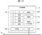
- FIG. 10 is a block diagram of a driver identification section (biometric authentication section) 1A connected to the in-vehicle network 18 of the vehicle V shown in FIG.
- the information management system 1 of this embodiment mainly includes a driver identification unit 1A shown in FIG. 10 in place of the driver identification unit 111 of the key authentication unit 11 shown in FIG.
- the driver identification unit 1A includes, for example, an interface unit 1A1, an authentication unit 1A2, an authentication information acquisition unit 1A3, an authentication information storage unit 1A4, a registration unit 1A5, and a verification unit 1A6. I have.
- the interface unit 1A1 is connected to the in-vehicle network 18, transmits information to the in-vehicle network 18, and receives information from the in-vehicle network 18.
- the authentication unit 1A2 has the same configuration as the authentication units 115, 126, and 138 included in the key authentication unit 11, the information acquisition unit 12, the information management unit 13, etc., and performs message authentication of information transmitted and received via the interface unit 1A1. conduct.
- the authentication information acquisition unit 1A3 is a sensor that acquires the biometric information BI of the driver of the vehicle V.
- the biometric information BI includes, for example, fingerprint information, finger vein information, palm vein information, face image information, iris image information, and the like.
- the authentication information acquisition unit 1A3 is, for example, an imaging unit such as a camera that captures a facial image of the driver.
- the authentication information acquisition unit 1A3 may be another sensor such as a fingerprint sensor.
- the authentication information storage unit 1A4 is configured by, for example, a non-volatile memory, and stores personal identification information PI of the driver and biometric information BI such as data based on a face image in association with each other.
- the registration unit 1A5 stores and registers the biometric information BI acquired by the authentication information acquisition unit 1A3 in the authentication information storage unit 1A4 in association with the personal identification information PI. At least in the vehicle V, unique personal identification information PI is associated with each individual biometric information BI.
- the collation unit 1A6 collates the biometric information BI acquired by the authentication information acquisition unit 1A3 with the biometric information BI stored in the authentication information storage unit 1A4. If the biometric information BI acquired by the authentication information acquisition unit 1A3 matches the biometric information BI stored in the authentication information storage unit 1A4, the verification unit 1A6 associates the biometric information BI from the authentication information storage unit 1A4. obtain the personal identification information PI.
- the verification unit 1A6 transmits the personal identification information PI acquired from the authentication information storage unit 1A4 to the information acquisition unit 12 or the secret key storage unit 133, for example.
- the electronic key 2 shown in FIG. 3 and the PDA 3 shown in FIG. 4 transmit only the vehicle identification number VIN to the key authentication unit 11, for example.
- the key authentication unit 11 shown in FIG. 6 does not have the driver identification unit 111 because it is only necessary to authenticate the vehicle identification number VIN.
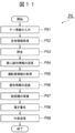
- FIG. 11 is a flow diagram showing an example of the flow of processing P5 of the information management system 1 of this embodiment.
- the key input unit 14 mounted on the vehicle V communicates with the electronic key 2 or PDA 3 possessed by the driver. Thereby, the key input unit 14 receives the encrypted vehicle identification number VIN from the electronic key 2 or the PDA 3 . Then, the information management system 1, for example, starts the process P5 shown in FIG. 11 and executes the key information input process P51.
- the VIN comparison unit 113 obtains the encrypted vehicle identification number VIN from the key input unit 14, decrypts the obtained vehicle identification number VIN, and decrypts it. Furthermore, the VIN comparison unit 113 compares the vehicle identification number VIN acquired from the key input unit 14 and the vehicle identification number VIN stored in the VIN storage unit 112, and does not start the vehicle V if they do not match. In this case, the information management system 1 terminates the processing shown in FIG.
- the information management system 1 executes biometric information acquisition processing P52, for example.
- the driver identification unit 1A acquires the biometric information BI of the driver, for example, by the authentication information acquisition unit 1A3. More specifically, for example, the imaging section as the authentication information acquisition section 1A3 acquires a face image by photographing the driver's face.
- the information management system 1 executes a matching process P53.
- the driver identification unit 1A uses the collation unit 1A6 to collate the biometric information BI acquired by the authentication information acquisition unit 1A3 with the biometric information BI stored in the authentication information storage unit 1A4. If they do not match, the information management system 1 causes, for example, the registration unit 1A5 to associate the biometric information BI acquired by the authentication information acquisition unit 1A3 with the unique personal identification information PI and store it in the authentication information storage unit 1A4. sign up.
- the matching unit 1A6 retrieves the personal identification information PI associated with the biometric information BI. is obtained from the authentication information storage unit 1A4.
- the information management system 1 executes the transmission process P54 of the personal identification information PI.
- the information management system 1 transmits the personal identification information PI acquired by the collation unit 1A6 to the information acquisition unit 12 and the information management unit 13 via the interface unit 1A1 and the in-vehicle network 18. Thereafter, the information management system 1 performs the driver information DI acquisition process P13, the individual information PD transmission process P14, the secret key SK preparation process P15, the electronic signature process P16, and the external transmission process shown in FIG. Processes P55, P56, P57, P58 and P59 similar to P17 are executed. Accordingly, the individual information PD of the vehicle V is transmitted to the outside of the vehicle V.
- the driver identification unit 1A includes the authentication information acquisition unit 1A3 that acquires the biometric information BI of the driver, and the biometric information BI and the personal identification information PI that are associated with each other.
- the matching unit 1A6 obtains the personal identification information PI associated with the matching biometric information BI. is obtained from the authentication information storage unit 1A4.
- the same effects as those of the information management system 1 of the second embodiment can be obtained without acquiring the personal identification information PI from the electronic key 2 or the PDA 3. can.
- the driver identification unit, information acquisition unit, and information management unit of the information management system are configured by individual ECUs or microcontrollers.
- the information management system can also be constituted by one microcontroller, for example.
- the information management system may be configured as part of a vehicle control device mounted on a vehicle.
- driver identification unit 12 information acquisition unit 125 PD storage unit (individual information storage unit) 132 PD storage unit (individual information storage unit) 133 private key storage unit 135 electronic signature unit 136 public key generation unit 137 HSM (hardware security module) 15 Communication unit 1A Driver identification unit 1A3 Authentication information acquisition unit 1A4 Authentication information storage unit 1A6 Verification unit 2 Electronic key 3 PDA (Personal Digital Assistant) BI Biometric information DI Driver information PD Individual information PI Personal identification information PK Public key SK Private key TI Driving information V Vehicle
Landscapes
- Engineering & Computer Science (AREA)
- Computer Security & Cryptography (AREA)
- Signal Processing (AREA)
- Computer Networks & Wireless Communication (AREA)
- Health & Medical Sciences (AREA)
- General Health & Medical Sciences (AREA)
- Theoretical Computer Science (AREA)
- Bioethics (AREA)
- General Engineering & Computer Science (AREA)
- Life Sciences & Earth Sciences (AREA)
- Software Systems (AREA)
- General Physics & Mathematics (AREA)
- Computer Hardware Design (AREA)
- Databases & Information Systems (AREA)
- Medical Informatics (AREA)
- Physics & Mathematics (AREA)
- Biodiversity & Conservation Biology (AREA)
- Biomedical Technology (AREA)
- Computing Systems (AREA)
- Management, Administration, Business Operations System, And Electronic Commerce (AREA)
- Traffic Control Systems (AREA)
- Lock And Its Accessories (AREA)
Abstract
Description
図1は、本開示に係る情報管理システムの実施形態1を示すブロック図である。図2は、実施形態1に係る情報管理システム1を搭載する車両Vのブロック図である。本実施形態の情報管理システム1は、車両Vの運転者に関する運転者情報を管理するシステムであり、たとえば、車両Vに搭載される車両システムである。車両Vは、たとえば、ガソリンエンジン車、ディーゼルエンジン車、ハイブリッド車、電気自動車、または、水素自動車である。

次に、本開示に係る情報管理システムの実施形態2について、図1、図3および図4を援用し、図6から図9を参照して説明する。図6は、実施形態2に係る情報管理システム1を搭載する車両Vのブロック図である。情報管理システム1は、主に、秘密鍵記憶部133および電子署名部135を含むハードウェアセキュリティモジュール137を備える点で、前述の実施形態1の情報管理システム1と異なっている。以下では、ハードウェアセキュリティモジュールを、「HSM」と略称する場合がある。
次に、本開示に係る情報管理システムの実施形態3について、図1、図3、図4および図6を援用し、図10および図11を参照して説明する。図10は、図6に示す車両Vの車載ネットワーク18に接続される運転者識別部(生体認証部)1Aのブロック図である。本実施形態の情報管理システム1は、主に、図6に示すキー認証部11の運転者識別部111に換えて、図10に示す運転者識別部1Aを備える点で、前述の実施形態2の情報管理システム1と異なっている。本実施形態の情報管理システム1のその他の構成は、前述の実施形態2の情報管理システム1と同様であるので、同様の部分には同一の符号を付して説明を省略する。
111 運転者識別部
12 情報取得部
125 PD記憶部(個別情報記憶部)
132 PD記憶部(個別情報記憶部)
133 秘密鍵記憶部
135 電子署名部
136 公開鍵生成部
137 HSM(ハードウェアセキュリティモジュール)
15 通信部
1A 運転者識別部
1A3 認証情報取得部
1A4 認証情報記憶部
1A6 照合部
2 電子キー
3 PDA(携帯情報端末)
BI 生体情報
DI 運転者情報
PD 個別情報
PI 個人識別情報
PK 公開鍵
SK 秘密鍵
TI 走行情報
V 車両
Claims (9)
- 車両の運転者に関する運転者情報を管理する情報管理システムであって、
前記運転者の個人識別情報を取得する運転者識別部と、
前記車両の走行情報を含む前記運転者情報を取得する情報取得部と、
前記個人識別情報と前記運転者情報を関連付けた個別情報を記憶する個別情報記憶部と、
を備えることを特徴とする情報管理システム。 - 前記車両の外部と通信可能な通信部と、
前記個人識別情報ごとに固有の秘密鍵が記憶された秘密鍵記憶部と、
前記個別情報に関連付けられた前記個人識別情報に固有の前記秘密鍵を用いて前記個別情報に電子署名を行う電子署名部と、をさらに備え、
前記通信部は、前記電子署名が付された前記個別情報を前記車両の外部へ送信することを特徴とする請求項1に記載の情報管理システム。 - 前記秘密鍵記憶部および前記電子署名部を含むハードウェアセキュリティモジュールを備えることを特徴とする請求項2に記載の情報管理システム。
- 前記車両の起動スイッチがオフにされたときに、前記個別情報記憶部に記憶された前記個別情報を消去することを特徴とする請求項2に記載の情報管理システム。
- 前記個別情報の消去前に、前記通信部を介して前記車両の外部へ前記個別情報を送信することを特徴とする請求項4に記載の情報管理システム。
- 前記車両の起動スイッチがオフにされたときに、前記個別情報記憶部の不揮発性記憶領域に前記個別情報を記憶させ、
前記車両の起動スイッチがオンにされたときに、前記個別情報記憶部の前記不揮発性記憶領域に記憶された前記個別情報を、前記通信部を介して前記車両の外部へ送信してから消去することを特徴とする請求項2に記載の情報管理システム。 - 前記運転者識別部は、前記車両の電子キーまたは前記運転者が所有する携帯情報端末から送信される前記個人識別情報を取得することを特徴とする請求項1に記載の情報管理システム。
- 前記運転者識別部は、前記運転者の生体情報を取得する認証情報取得部と、前記生体情報と前記個人識別情報とを関連付けて記憶する認証情報記憶部と、前記認証情報取得部によって取得された前記生体情報と前記認証情報記憶部に記憶された前記生体情報とを照合する照合部と、を備え、
前記照合部は、前記認証情報取得部によって取得された前記生体情報と前記認証情報記憶部に記憶された前記生体情報とが合致する場合に、合致した前記生体情報に関連付けられた前記個人識別情報を前記認証情報記憶部から取得することを特徴とする請求項1に記載の情報管理システム。 - 個々の前記個人識別情報に固有の前記秘密鍵に対応する公開鍵を生成する公開鍵生成部をさらに備え、
前記通信部は、前記公開鍵を外部へ送信することを特徴とする請求項2に記載の情報管理システム。
Priority Applications (3)
| Application Number | Priority Date | Filing Date | Title |
|---|---|---|---|
| DE112021005247.0T DE112021005247T5 (de) | 2021-02-16 | 2021-09-08 | Informationsmanagementsystem |
| US18/258,412 US12562914B2 (en) | 2021-02-16 | 2021-09-08 | Information management system |
| CN202180079727.1A CN116569238A (zh) | 2021-02-16 | 2021-09-08 | 信息管理系统 |
Applications Claiming Priority (2)
| Application Number | Priority Date | Filing Date | Title |
|---|---|---|---|
| JP2021-022213 | 2021-02-16 | ||
| JP2021022213A JP7606358B2 (ja) | 2021-02-16 | 2021-02-16 | 情報管理システム |
Publications (1)
| Publication Number | Publication Date |
|---|---|
| WO2022176240A1 true WO2022176240A1 (ja) | 2022-08-25 |
Family
ID=82931314
Family Applications (1)
| Application Number | Title | Priority Date | Filing Date |
|---|---|---|---|
| PCT/JP2021/033001 Ceased WO2022176240A1 (ja) | 2021-02-16 | 2021-09-08 | 情報管理システム |
Country Status (5)
| Country | Link |
|---|---|
| US (1) | US12562914B2 (ja) |
| JP (1) | JP7606358B2 (ja) |
| CN (1) | CN116569238A (ja) |
| DE (1) | DE112021005247T5 (ja) |
| WO (1) | WO2022176240A1 (ja) |
Families Citing this family (1)
| Publication number | Priority date | Publication date | Assignee | Title |
|---|---|---|---|---|
| US12531858B2 (en) * | 2023-09-28 | 2026-01-20 | Nvidia Corporation | Protecting controller area network (CAN) messages in autonomous systems and applications |
Citations (4)
| Publication number | Priority date | Publication date | Assignee | Title |
|---|---|---|---|---|
| JP2005303615A (ja) * | 2004-04-09 | 2005-10-27 | Nippon Telegr & Teleph Corp <Ntt> | 電子署名生成装置及び電子署名装置 |
| JP2009169486A (ja) * | 2008-01-11 | 2009-07-30 | Seiko Epson Corp | 運転情報記録システム及び運転情報記録方法 |
| JP2014235609A (ja) * | 2013-06-03 | 2014-12-15 | 株式会社堀場製作所 | 運行管理システム、運行記録装置、及び管理プログラム |
| JP2020017805A (ja) * | 2018-07-23 | 2020-01-30 | Kddi株式会社 | 車両情報送信装置、車両情報受信装置、車両情報通信方法及びコンピュータプログラム |
Family Cites Families (9)
| Publication number | Priority date | Publication date | Assignee | Title |
|---|---|---|---|---|
| US20180013873A1 (en) * | 2008-01-31 | 2018-01-11 | Sirius Xm Connected Vehicle Services Inc. | Method of Providing Driver-Behavior Information Off-Site Through Telematics System |
| JP5272815B2 (ja) * | 2009-03-11 | 2013-08-28 | オムロン株式会社 | 車両盗難防止装置、車両盗難防止方法、およびプログラム |
| US9208626B2 (en) * | 2011-03-31 | 2015-12-08 | United Parcel Service Of America, Inc. | Systems and methods for segmenting operational data |
| US9361271B2 (en) * | 2011-09-27 | 2016-06-07 | Wipro Limited | Systems and methods to enable eco-driving |
| US9402174B2 (en) * | 2013-05-06 | 2016-07-26 | Verizon Telematics Inc. | Vehicle driver identification using portable device |
| US9898759B2 (en) * | 2014-03-28 | 2018-02-20 | Joseph Khoury | Methods and systems for collecting driving information and classifying drivers and self-driving systems |
| US10127749B2 (en) * | 2016-01-11 | 2018-11-13 | Ford Global Technologies, Llc | System and method for profile indication on a key fob |
| JP2018055191A (ja) | 2016-09-26 | 2018-04-05 | 株式会社日立製作所 | データ収集システム |
| US10259468B2 (en) * | 2017-06-15 | 2019-04-16 | Hitachi, Ltd. | Active vehicle performance tuning based on driver behavior |
-
2021
- 2021-02-16 JP JP2021022213A patent/JP7606358B2/ja active Active
- 2021-09-08 WO PCT/JP2021/033001 patent/WO2022176240A1/ja not_active Ceased
- 2021-09-08 US US18/258,412 patent/US12562914B2/en active Active
- 2021-09-08 CN CN202180079727.1A patent/CN116569238A/zh active Pending
- 2021-09-08 DE DE112021005247.0T patent/DE112021005247T5/de active Pending
Patent Citations (4)
| Publication number | Priority date | Publication date | Assignee | Title |
|---|---|---|---|---|
| JP2005303615A (ja) * | 2004-04-09 | 2005-10-27 | Nippon Telegr & Teleph Corp <Ntt> | 電子署名生成装置及び電子署名装置 |
| JP2009169486A (ja) * | 2008-01-11 | 2009-07-30 | Seiko Epson Corp | 運転情報記録システム及び運転情報記録方法 |
| JP2014235609A (ja) * | 2013-06-03 | 2014-12-15 | 株式会社堀場製作所 | 運行管理システム、運行記録装置、及び管理プログラム |
| JP2020017805A (ja) * | 2018-07-23 | 2020-01-30 | Kddi株式会社 | 車両情報送信装置、車両情報受信装置、車両情報通信方法及びコンピュータプログラム |
Also Published As
| Publication number | Publication date |
|---|---|
| US12562914B2 (en) | 2026-02-24 |
| JP7606358B2 (ja) | 2024-12-25 |
| US20240048388A1 (en) | 2024-02-08 |
| JP2022124521A (ja) | 2022-08-26 |
| CN116569238A (zh) | 2023-08-08 |
| DE112021005247T5 (de) | 2023-07-27 |
Similar Documents
| Publication | Publication Date | Title |
|---|---|---|
| JP5435022B2 (ja) | 車載システム及び通信方法 | |
| US10645578B2 (en) | System for using mobile terminals as keys for vehicles | |
| JP5999108B2 (ja) | 車両遠隔操作情報提供装置、車載遠隔操作情報取得装置及びこれらの装置を備えた車両遠隔操作システム | |
| JP5120437B2 (ja) | 車載機、車両用認証システム及びデータ通信方法 | |
| CN104429042B (zh) | 基于证书的控制单元遥控钥匙配对 | |
| US11263848B2 (en) | Temporary and customized vehicle access | |
| EP2876553A1 (en) | Information processing program, information processing method, and information processing apparatus | |
| US11014535B2 (en) | Shared vehicle security | |
| CN107453870A (zh) | 基于区块链的移动终端认证管理方法、装置及相应的移动终端 | |
| CN110191415B (zh) | 一种车辆信息的加密方法、车载设备及服务器 | |
| JP5879451B1 (ja) | 車両を管理するシステム及び方法 | |
| CN104702589A (zh) | 用于虚拟钥匙传送的方法和设备 | |
| JP5714453B2 (ja) | 車両通信装置 | |
| JP2016208494A (ja) | 車両を管理するシステム及び方法 | |
| CN111831985B (zh) | 利用身份识别设备提供车队系统的方法和装置 | |
| JP7606358B2 (ja) | 情報管理システム | |
| WO2020137897A1 (ja) | サービス提供システム、制御装置、およびサービス提供方法 | |
| US9037412B2 (en) | Mechanism to monitor vehicle miles traveled | |
| JP6575697B2 (ja) | 車両用情報処理システム及び車両用情報処理プログラム、並びに携帯通信端末 | |
| WO2009014257A1 (ja) | 車両のデータ通信システム及び車両 | |
| US11882440B2 (en) | Authentication system and method for connected car service | |
| US20260138564A1 (en) | Information processing method, information processing device, and recording medium | |
| JP2025030387A (ja) | 制御装置、サーバ、制御方法、及びプログラム | |
| JP2023180073A (ja) | サーバ装置、データ変更方法、プログラム、およびデータ変更システム | |
| CN119832656A (zh) | 对机动车的访问控制 |
Legal Events
| Date | Code | Title | Description |
|---|---|---|---|
| 121 | Ep: the epo has been informed by wipo that ep was designated in this application |
Ref document number: 21926669 Country of ref document: EP Kind code of ref document: A1 |
|
| WWE | Wipo information: entry into national phase |
Ref document number: 202180079727.1 Country of ref document: CN |
|
| WWE | Wipo information: entry into national phase |
Ref document number: 18258412 Country of ref document: US |
|
| 122 | Ep: pct application non-entry in european phase |
Ref document number: 21926669 Country of ref document: EP Kind code of ref document: A1 |
|
| WWG | Wipo information: grant in national office |
Ref document number: 18258412 Country of ref document: US |