WO2022176162A1 - 無線通信方法、無線通信システム、および無線通信プログラム - Google Patents
無線通信方法、無線通信システム、および無線通信プログラム Download PDFInfo
- Publication number
- WO2022176162A1 WO2022176162A1 PCT/JP2021/006387 JP2021006387W WO2022176162A1 WO 2022176162 A1 WO2022176162 A1 WO 2022176162A1 JP 2021006387 W JP2021006387 W JP 2021006387W WO 2022176162 A1 WO2022176162 A1 WO 2022176162A1
- Authority
- WO
- WIPO (PCT)
- Prior art keywords
- reflector
- wireless communication
- area
- obstacle
- station
- Prior art date
- Legal status (The legal status is an assumption and is not a legal conclusion. Google has not performed a legal analysis and makes no representation as to the accuracy of the status listed.)
- Ceased
Links
Images


Classifications
-
- H—ELECTRICITY
- H04—ELECTRIC COMMUNICATION TECHNIQUE
- H04B—TRANSMISSION
- H04B7/00—Radio transmission systems, i.e. using radiation field
- H04B7/14—Relay systems
- H04B7/15—Active relay systems
- H04B7/155—Ground-based stations
- H04B7/15507—Relay station based processing for cell extension or control of coverage area
- H04B7/15514—Relay station based processing for cell extension or control of coverage area for shadowing compensation
-
- H—ELECTRICITY
- H04—ELECTRIC COMMUNICATION TECHNIQUE
- H04B—TRANSMISSION
- H04B7/00—Radio transmission systems, i.e. using radiation field
- H04B7/14—Relay systems
- H04B7/145—Passive relay systems
-
- Y—GENERAL TAGGING OF NEW TECHNOLOGICAL DEVELOPMENTS; GENERAL TAGGING OF CROSS-SECTIONAL TECHNOLOGIES SPANNING OVER SEVERAL SECTIONS OF THE IPC; TECHNICAL SUBJECTS COVERED BY FORMER USPC CROSS-REFERENCE ART COLLECTIONS [XRACs] AND DIGESTS
- Y02—TECHNOLOGIES OR APPLICATIONS FOR MITIGATION OR ADAPTATION AGAINST CLIMATE CHANGE
- Y02D—CLIMATE CHANGE MITIGATION TECHNOLOGIES IN INFORMATION AND COMMUNICATION TECHNOLOGIES [ICT], I.E. INFORMATION AND COMMUNICATION TECHNOLOGIES AIMING AT THE REDUCTION OF THEIR OWN ENERGY USE
- Y02D30/00—Reducing energy consumption in communication networks
- Y02D30/70—Reducing energy consumption in communication networks in wireless communication networks
Definitions
- the present invention relates to a wireless communication method, a wireless communication system, and a wireless communication program.
- Non-Patent Document 1 discloses a technique for varying the radio wave propagation environment by using a combination of repeaters such as reflectors.
- An object of the present invention is to provide a wireless communication system, a wireless communication method, and a wireless communication program capable of securing a line-of-sight communication path.
- a wireless communication system is a wireless communication system in which radio waves transmitted by a transmitting station toward a receiving station are reflected by a plurality of reflectors.
- This wireless communication system includes a sensor unit that acquires data related to the position of an obstacle existing between a transmitting station and a receiving station, and an area where the obstacle exists based on the data acquired by the sensor unit.
- an obstacle area detection unit for detecting an obstacle area; and an obstacle area opposite side of the obstacle area with reference to a tangent line from the transmitting station to the obstacle area and opposite side of the obstacle area with reference to a tangent line from the receiving station to the obstacle area.
- a reflector area setting unit that sets the area on the side as a reflector setting area; a reflector selection unit that selects a reflector existing in the reflector setting area from among the plurality of reflectors; and a reflector selection unit a control unit for controlling communication so that the receiving station and the transmitting station perform wireless communication by means of radio waves reflected by the selected reflector.
- a wireless communication method is a wireless communication method in which radio waves transmitted by a transmitting station toward a receiving station are reflected by a plurality of reflectors.
- This wireless communication method includes a sensor step of acquiring data related to the position of an obstacle existing between a transmitting station and a receiving station, and an area where the obstacle exists based on the data acquired in the sensor step.
- an obstacle area detection step for detecting an obstacle area; and an obstacle area opposite side of the obstacle area with reference to a tangent line from the transmitting station to the obstacle area and opposite side of the obstacle area with reference to a tangent line from the receiving station to the obstacle area.
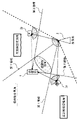
- FIG. 1 is a diagram schematically showing a configuration example of a radio communication system according to Embodiment 1;
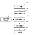
- FIG. 2 is a functional block diagram showing main functions of the wireless communication system according to Embodiment 1;
- FIG. 4 is a flow chart showing an operation example of the radio communication system according to Embodiment 1;
- FIG. 2 is a diagram showing a modification of the radio communication system according to Embodiment 1;
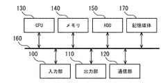
- FIG. 2 is a diagram illustrating a hardware configuration example that implements each function of a wireless communication system;
- FIG. 1 is a diagram schematically showing a configuration example of a radio communication system according to Embodiment 1.
- FIG. FIG. 2 is a functional block diagram showing main functions of the radio communication system according to the first embodiment.
- the wireless communication system is a system that realizes a favorable radio wave propagation environment by reflecting the radio waves transmitted by the transmitting station 2 toward the receiving station 1 using a plurality of reflectors.
- a wireless communication system can be implemented as a single device or by a plurality of devices working together.
- Each of the multiple reflectors that make up the wireless communication system has the function of reflecting and relaying the radio waves transmitted by the transmitting station 2 .
- the multiple reflectors include a first reflector 3a and a second reflector 3b.
- the wireless communication system according to the present embodiment includes a sensor section 10, an obstacle area detection section 11, a reflector area setting section 12, a reflector selection section 13, and a control section 14.
- the wireless communication system according to the present embodiment includes a reflector information holding unit 15 as a database in which information such as the positions of a plurality of reflectors is held.
- the sensor unit 10 acquires data related to the position of an obstacle that exists between the transmitting station 2 and the receiving station 1.
- an “obstacle” in the present disclosure means an object that shields radio waves transmitted by the transmitting station 2 .
- the sensor unit 10 is a sensing device for detecting the position of obstacles existing in the radio wave propagation environment realized by the wireless communication system.
- the sensor unit 10 corresponds to, for example, a 3D laser scanner that acquires point cloud data, a camera that captures an actual image, and the like.
- the type of equipment that configures the sensor unit 10 and the type of data acquired by the sensor unit 10 are not limited.
- the sensor unit 10 can be arbitrarily configured as long as it can acquire data for detecting the position of an obstacle.
- the sensor unit 10 outputs the acquired data to the obstacle area detection unit 11.
- the obstacle area detection unit 11 detects an obstacle area, which is an area in which an obstacle exists, based on the data acquired by the sensor unit 10 .
- the obstacle area detection unit 11 outputs data of the detected obstacle area to the reflector area setting unit 12 .
- the reflector area setting unit 12 sets the reflector setting area based on the obstacle area data detected by the obstacle area detection unit 11 .
- a first tangent line extending from the transmitting station 2 to the obstacle area and a second tangent line extending from the receiving station 1 to the obstacle area are drawn.
- an area opposite to the obstacle area with respect to the first tangent and opposite to the obstacle area with respect to the second tangent is set as a reflector setting area.
- the reflector area setting unit 12 extracts the data of the reflector existing in the set reflector setting area based on the data held in the reflector information holding unit 15 .
- the reflector region setting unit 12 outputs the extracted reflector data to the reflector selector 13 .
- the reflector selection unit 13 selects reflectors to be used in the wireless communication system based on the data output from the reflector area setting unit 12 .
- the reflector selection unit 13 selects a reflector existing in the reflector setting area from among the plurality of reflectors.
- the control unit 14 controls each unit that constitutes the wireless communication system. Specifically, the control unit 14 controls communication between the receiving station 1, the transmitting station 2, and each reflector. In the present embodiment, the control unit 14 controls communication so that the reception station 1 and the transmission station 2 perform wireless communication using radio waves reflected by the reflector selected by the reflector selection unit 13 .
- the first reflector 3a is positioned within the reflector setting area.
- the first reflector 3 a is a reflector that can be selected by the reflector selector 13 .
- the second reflector 3b is positioned outside the reflector set area.
- the second reflector 3 b is a reflector that cannot be selected by the reflector selector 13 .
- a communication path between the first reflector 3a and the transmitting station 2 is a line-of-sight communication path.
- a communication path between the first reflector 3a and the receiving station 1 located within the reflector set area is a line-of-sight communication path.
- a communication path between the first reflector 3a and the transmitting station 2 is a line-of-sight communication path.
- an obstacle area exists between the second reflector 3b located outside the reflector set area and the receiving station 1 .
- the communication path between the second reflector 3b and the receiving station 1 is not a line-of-sight communication path.
- the first reflector 3 a is selected by the reflector selector 13 .
- both the communication path between the first reflector 3a and the transmitting station 2 and the communication path between the first reflector 3a and the receiving station 1 can be made visible.
- FIG. 3 is a flowchart illustrating an operation example of the radio communication system according to Embodiment 1.
- FIG. 3 is a flowchart illustrating an operation example of the radio communication system according to Embodiment 1.
- the sensor unit 10 acquires data related to the position of the obstacle (S101). Then, based on the acquired data, the obstacle area detection section 11 detects an obstacle area (S102).
- a line-of-sight environment between the transmitting station 2 and the receiving station 1 means that an obstacle area does not exist between the transmitting station 2 and the receiving station 1 .
- the determination in S103 is made based on the data of the obstacle area detected by the obstacle area detection unit 11. FIG. Note that the determination in S103 may be performed by the obstacle area detection unit 11, or a separate determination unit having the function of performing the determination may be provided.
- the subsequent processing is not performed, and communication between the transmitting station 2 and the receiving station 1 is performed without relaying the reflector. done.
- the reflector area is set by the reflector area setting unit 12 as described above (S104). Then, the reflector within the reflector area is selected by the reflector selector 13, and the controller 14 performs control so that communication using the reflector is performed (S105).
- each function of the wireless communication system can also be implemented as a wireless communication method.
- FIG. 4 is a diagram showing a modification of the radio communication system according to Embodiment 1.
- This modification is characterized by considering the directivity of the transmitting station 2 and the directivity of each reflector.
- the reflector selection unit 13 selects a reflector existing within the directivity range of the transmitting station 2 and within the directivity range of the reflector among the reflectors existing in the reflector setting area. is characterized by selecting the one where the receiving station 1 is located in.
- the second reflector 3b is positioned within the reflector set area
- the receiving station 1 is not positioned within the directivity range of the second reflector 3b.
- the first reflector 3 a exists within the reflector set area and within the directivity range of the transmitting station 2 .
- the receiving station 1 is positioned within the directivity range of the first reflector 3a.
- the first reflector 3a is selected and used. According to this modification, a better radio wave propagation environment can be obtained by considering the directivity.
- each function of the wireless communication system is partially or wholly implemented by hardware such as ASIC (Application Specific Integrated Circuit), PLD (Programmable Logic Device), or FPGA (Field Programmable Gate Array). hardware.
- Each function of the wireless communication system may be realized by a combination of dedicated hardware and software.
- each function of the wireless communication system may be configured as a program that is partially or wholly executed by a processor such as a CPU. This program may be recorded on a computer-readable storage medium.
- a wireless communication system can be implemented using a computer and a program, and the program can be recorded on a storage medium or provided through a network.
- FIG. 5 is a diagram showing a hardware configuration example that implements each function of the wireless communication system.
- each function of the wireless communication system is implemented by, for example, an input unit 100, an output unit 110, a communication unit 120, a CPU 130, a memory 140, an HDD 150, and the like.
- Input unit 100, output unit 110, communication unit 120, CPU 130, memory 140, and HDD 150 are connected via bus 160 and function as a computer.
- the computer configured by the input unit 100, the output unit 110, the communication unit 120, the CPU 130, the memory 140, the HDD 150, etc. can input and output data to and from a computer-readable storage medium 170. It's becoming
- the input unit 100 is, for example, a keyboard and a mouse.
- the output unit 110 is, for example, a display device such as a display.
- the communication unit 120 is, for example, a wireless network interface.
- the CPU 130 controls each unit that constitutes the wireless communication system and performs predetermined processing.
- Memory 140 and HDD 150 function as storage units that store various data.
- a storage medium 170 stores a program for executing each function of the wireless communication system. Note that the architecture configuring the wireless communication system is not limited to the example shown in FIG.
- the "computer” here includes hardware such as the OS and peripheral devices.
- a “computer-readable storage medium” is, for example, a portable medium such as a flexible disk, a magneto-optical disk, a ROM, and a CD-ROM.
- “computer-readable storage medium” means a medium that dynamically stores programs for a short period of time, such as a communication line for transmitting a program via a network such as the Internet or a communication line such as a telephone line.
- the "computer-readable storage medium” may be a medium such as a volatile memory inside a computer serving as a server or a client, which holds a program for a certain period of time.
- the wireless communication system, wireless communication method, and wireless communication program according to the present invention can be applied, for example, to mobile base stations that provide wireless communication.
- Receiving Station 2 Transmitting Station 3a First Reflector 3b Second Reflector 10 Sensor Unit REFERENCE SIGNS LIST 11 obstacle area detection unit 12 reflector area setting unit 13 reflector selection unit 14 control unit 15 reflector information storage unit 100 input unit 110 output unit 120 communication unit 130 CPU 140 memory 150 HDD 160 bus 170 storage medium
Landscapes
- Engineering & Computer Science (AREA)
- Computer Networks & Wireless Communication (AREA)
- Signal Processing (AREA)
- Mobile Radio Communication Systems (AREA)
- Radio Relay Systems (AREA)
Abstract
Description
図1は、実施の形態1に係る無線通信システムの構成例を模式的に示す図である。図2は、実施の形態1に係る無線通信システムの主要な機能を示す機能ブロック図である。
2 送信局
3a 第1反射板
3b 第2反射板
10 センサ部
11 障害物領域検出部
12 反射板領域設定部
13 反射板選択部
14 制御部
15 反射板情報保持部
100 入力部
110 出力部
120 通信部
130 CPU
140 メモリ
150 HDD
160 バス
170 記憶媒体
Claims (5)
- 受信局に向けて送信局が送信する電波を複数の反射板によって反射させる無線通信システムにおいて、
前記送信局と前記受信局との間に存在する障害物の位置に関連するデータを取得するセンサ部と、
前記センサ部が取得したデータに基づいて、前記障害物が存在する領域である障害物領域を検出する障害物領域検出部と、
前記送信局から前記障害物領域に向かう接線を基準として前記障害物領域の反対側で且つ前記受信局から前記障害物領域に向かう接線を基準として前記障害物領域の反対側である領域を、反射板設定領域として設定する反射板領域設定部と、
前記複数の反射板のうち、前記反射板設定領域に存在する反射板を選択する反射板選択部と、
前記反射板選択部が選択した前記反射板が反射させる電波によって前記受信局と前記送信局とが無線通信を行うように通信を制御する制御部と、
を備えることを特徴とする無線通信システム。 - 前記反射板選択部は、前記反射板設定領域に存在する前記反射板のうち、前記送信局の指向性の範囲内に存在し且つ当該反射板の指向性の範囲内に前記受信局が位置するもの、を選択することを特徴とする請求項1に記載の無線通信システム。
- 受信局に向けて送信局が送信する電波を複数の反射板によって反射させる無線通信方法において、
前記送信局と前記受信局との間に存在する障害物の位置に関連するデータを取得するセンサ工程と、
前記センサ工程で取得したデータに基づいて、前記障害物が存在する領域である障害物領域を検出する障害物領域検出工程と、
前記送信局から前記障害物領域に向かう接線を基準として前記障害物領域の反対側で且つ前記受信局から前記障害物領域に向かう接線を基準として前記障害物領域の反対側である領域を、反射板設定領域として設定する反射板領域設定工程と、
前記複数の反射板のうち、前記反射板設定領域に存在する反射板を選択する反射板選択工程と、
前記反射板選択工程で選択した前記反射板が反射させる電波によって前記受信局と前記送信局とが無線通信を行うように通信を制御する制御工程と、
を備えることを特徴とする無線通信方法。 - 前記反射板選択工程は、前記反射板設定領域に存在する前記反射板のうち、前記送信局の指向性の範囲内に存在し且つ当該反射板の指向性の範囲内に前記受信局が位置するもの、を選択することを特徴とする請求項3に記載の無線通信方法。
- 請求項1または請求項2に記載の無線通信システムの各部としてコンピュータを機能させるための無線通信プログラム。
Priority Applications (3)
| Application Number | Priority Date | Filing Date | Title |
|---|---|---|---|
| JP2023500463A JP7552848B2 (ja) | 2021-02-19 | 2021-02-19 | 無線通信方法、無線通信システム、および無線通信プログラム |
| US18/275,233 US20240097775A1 (en) | 2021-02-19 | 2021-02-19 | Wireless communication method, wireless communication system, and wireless communication program |
| PCT/JP2021/006387 WO2022176162A1 (ja) | 2021-02-19 | 2021-02-19 | 無線通信方法、無線通信システム、および無線通信プログラム |
Applications Claiming Priority (1)
| Application Number | Priority Date | Filing Date | Title |
|---|---|---|---|
| PCT/JP2021/006387 WO2022176162A1 (ja) | 2021-02-19 | 2021-02-19 | 無線通信方法、無線通信システム、および無線通信プログラム |
Publications (1)
| Publication Number | Publication Date |
|---|---|
| WO2022176162A1 true WO2022176162A1 (ja) | 2022-08-25 |
Family
ID=82930431
Family Applications (1)
| Application Number | Title | Priority Date | Filing Date |
|---|---|---|---|
| PCT/JP2021/006387 Ceased WO2022176162A1 (ja) | 2021-02-19 | 2021-02-19 | 無線通信方法、無線通信システム、および無線通信プログラム |
Country Status (3)
| Country | Link |
|---|---|
| US (1) | US20240097775A1 (ja) |
| JP (1) | JP7552848B2 (ja) |
| WO (1) | WO2022176162A1 (ja) |
Cited By (1)
| Publication number | Priority date | Publication date | Assignee | Title |
|---|---|---|---|---|
| WO2026042172A1 (ja) * | 2024-08-20 | 2026-02-26 | Ntt株式会社 | 対応付け処理装置、対応付け方法、及び対応付けプログラム |
Citations (4)
| Publication number | Priority date | Publication date | Assignee | Title |
|---|---|---|---|---|
| JP2002204196A (ja) * | 2000-10-31 | 2002-07-19 | Icom Inc | 無線通信機 |
| JP2005323266A (ja) * | 2004-05-11 | 2005-11-17 | Kobe Steel Ltd | 無線ネットワーク通信システム,及びこのシステムに用いられる中継無線端末並びに発信元の無線端末,及び無線通信経路のルーティング方法 |
| JP2018165099A (ja) * | 2017-03-28 | 2018-10-25 | パナソニックIpマネジメント株式会社 | 無線通信システム、制御装置、中継装置および無線通信制御方法 |
| JP2019009531A (ja) * | 2017-06-21 | 2019-01-17 | ソフトバンク株式会社 | 無給電中継装置及び無線中継システム |
-
2021
- 2021-02-19 WO PCT/JP2021/006387 patent/WO2022176162A1/ja not_active Ceased
- 2021-02-19 US US18/275,233 patent/US20240097775A1/en not_active Abandoned
- 2021-02-19 JP JP2023500463A patent/JP7552848B2/ja active Active
Patent Citations (4)
| Publication number | Priority date | Publication date | Assignee | Title |
|---|---|---|---|---|
| JP2002204196A (ja) * | 2000-10-31 | 2002-07-19 | Icom Inc | 無線通信機 |
| JP2005323266A (ja) * | 2004-05-11 | 2005-11-17 | Kobe Steel Ltd | 無線ネットワーク通信システム,及びこのシステムに用いられる中継無線端末並びに発信元の無線端末,及び無線通信経路のルーティング方法 |
| JP2018165099A (ja) * | 2017-03-28 | 2018-10-25 | パナソニックIpマネジメント株式会社 | 無線通信システム、制御装置、中継装置および無線通信制御方法 |
| JP2019009531A (ja) * | 2017-06-21 | 2019-01-17 | ソフトバンク株式会社 | 無給電中継装置及び無線中継システム |
Cited By (1)
| Publication number | Priority date | Publication date | Assignee | Title |
|---|---|---|---|---|
| WO2026042172A1 (ja) * | 2024-08-20 | 2026-02-26 | Ntt株式会社 | 対応付け処理装置、対応付け方法、及び対応付けプログラム |
Also Published As
| Publication number | Publication date |
|---|---|
| JPWO2022176162A1 (ja) | 2022-08-25 |
| US20240097775A1 (en) | 2024-03-21 |
| JP7552848B2 (ja) | 2024-09-18 |
Similar Documents
| Publication | Publication Date | Title |
|---|---|---|
| WO2022176163A1 (ja) | 無線通信方法、無線通信システム、および無線通信プログラム | |
| CN110914699A (zh) | 基于信标的位置感知系统 | |
| WO2022068705A1 (zh) | 用于调整位置信息的方法、设备和系统 | |
| US10725181B2 (en) | In-band pseudolite wireless positioning method, system and device | |
| KR102042105B1 (ko) | 지형지물을 고려한 이기종 무선 시스템 간의 간섭 분석 장치 및 방법 | |
| JP2024522315A (ja) | スマートサーフェス機器の識別方法、通信機器及びスマートサーフェス機器 | |
| US20190208395A1 (en) | Method and Apparatus For Identifying A Target Device | |
| WO2016037569A1 (zh) | 无线通信连接的建立方法及终端设备 | |
| WO2022176162A1 (ja) | 無線通信方法、無線通信システム、および無線通信プログラム | |
| KR101791258B1 (ko) | 단말기 측위 시스템 및 방법, 측위 장치 및 그 장치의 구동 방법, 클라우드 컴퓨팅 서비스 장치 및 그 장치의 구동 방법, 액세스포인트 및 액세스포인트의 구동 방법, 단말기 | |
| JP6331072B2 (ja) | ホワイトスペース検出装置、ホワイトスペース検出方法、及びプログラム | |
| CN108828573B (zh) | 电力线定位方法、装置、系统和计算机存储介质 | |
| CN110574301A (zh) | 基于组合的波束的波束成形 | |
| CN109885940A (zh) | 一种多径条件下波达分布的数学建模方法 | |
| KR102169688B1 (ko) | 장소정보 제공방법 및 그 시스템 | |
| Moriyama et al. | Controlling of communication connection range using acoustic waves emitted from smartphones | |
| WO2023145013A1 (ja) | 中継デバイス制御装置、中継デバイス制御方法、中継デバイス制御プログラムおよび無線通信システム | |
| US12255702B2 (en) | Relay system, relay control device, relay method, and relay control program | |
| US12231987B2 (en) | RSSI location tracking via radio scanning for triggered OFDMA uplink | |
| KR102667107B1 (ko) | 건설현장의 인원 관리를 위한 블루투스를 이용한 위치 모니터링의 컴퓨팅 시스템 및 그의 방법 | |
| JP6311198B2 (ja) | ホワイトスペース検出装置、ホワイトスペース検出方法、及びプログラム | |
| WO2026047842A1 (ja) | 通信装置、通信システム、通信方法、及びプログラム | |
| WO2025228862A1 (en) | Multi-operator joint communication and sensing | |
| JP7674192B2 (ja) | ビームを形成して基地局装置と端末装置との間の通信の中継を行う中継装置、制御方法、及びプログラム | |
| CN118138098A (zh) | 波束转发方法、装置及可读存储介质 |
Legal Events
| Date | Code | Title | Description |
|---|---|---|---|
| 121 | Ep: the epo has been informed by wipo that ep was designated in this application |
Ref document number: 21926595 Country of ref document: EP Kind code of ref document: A1 |
|
| ENP | Entry into the national phase |
Ref document number: 2023500463 Country of ref document: JP Kind code of ref document: A |
|
| WWE | Wipo information: entry into national phase |
Ref document number: 18275233 Country of ref document: US |
|
| NENP | Non-entry into the national phase |
Ref country code: DE |
|
| 122 | Ep: pct application non-entry in european phase |
Ref document number: 21926595 Country of ref document: EP Kind code of ref document: A1 |