WO2022162897A1 - Uボルト、施工方法及び検出装置 - Google Patents
Uボルト、施工方法及び検出装置 Download PDFInfo
- Publication number
- WO2022162897A1 WO2022162897A1 PCT/JP2021/003352 JP2021003352W WO2022162897A1 WO 2022162897 A1 WO2022162897 A1 WO 2022162897A1 JP 2021003352 W JP2021003352 W JP 2021003352W WO 2022162897 A1 WO2022162897 A1 WO 2022162897A1
- Authority
- WO
- WIPO (PCT)
- Prior art keywords
- thin film
- bolt
- strain
- phc
- photonic crystal
- Prior art date
- Legal status (The legal status is an assumption and is not a legal conclusion. Google has not performed a legal analysis and makes no representation as to the accuracy of the status listed.)
- Ceased
Links
Images







Classifications
-
- F—MECHANICAL ENGINEERING; LIGHTING; HEATING; WEAPONS; BLASTING
- F16—ENGINEERING ELEMENTS AND UNITS; GENERAL MEASURES FOR PRODUCING AND MAINTAINING EFFECTIVE FUNCTIONING OF MACHINES OR INSTALLATIONS; THERMAL INSULATION IN GENERAL
- F16L—PIPES; JOINTS OR FITTINGS FOR PIPES; SUPPORTS FOR PIPES, CABLES OR PROTECTIVE TUBING; MEANS FOR THERMAL INSULATION IN GENERAL
- F16L3/00—Supports for pipes, cables or protective tubing, e.g. hangers, holders, clamps, cleats, clips, brackets
- F16L3/08—Supports for pipes, cables or protective tubing, e.g. hangers, holders, clamps, cleats, clips, brackets substantially surrounding the pipe, cable or protective tubing
- F16L3/12—Supports for pipes, cables or protective tubing, e.g. hangers, holders, clamps, cleats, clips, brackets substantially surrounding the pipe, cable or protective tubing comprising a member substantially surrounding the pipe, cable or protective tubing
- F16L3/1207—Supports for pipes, cables or protective tubing, e.g. hangers, holders, clamps, cleats, clips, brackets substantially surrounding the pipe, cable or protective tubing comprising a member substantially surrounding the pipe, cable or protective tubing the ends of the member and the fixing elements being placed on both sides of the pipe
-
- F—MECHANICAL ENGINEERING; LIGHTING; HEATING; WEAPONS; BLASTING
- F16—ENGINEERING ELEMENTS AND UNITS; GENERAL MEASURES FOR PRODUCING AND MAINTAINING EFFECTIVE FUNCTIONING OF MACHINES OR INSTALLATIONS; THERMAL INSULATION IN GENERAL
- F16B—DEVICES FOR FASTENING OR SECURING CONSTRUCTIONAL ELEMENTS OR MACHINE PARTS TOGETHER, e.g. NAILS, BOLTS, CIRCLIPS, CLAMPS, CLIPS OR WEDGES; JOINTS OR JOINTING
- F16B35/00—Screw-bolts; Stay-bolts; Screw-threaded studs; Screws; Set screws
-
- F—MECHANICAL ENGINEERING; LIGHTING; HEATING; WEAPONS; BLASTING
- F16—ENGINEERING ELEMENTS AND UNITS; GENERAL MEASURES FOR PRODUCING AND MAINTAINING EFFECTIVE FUNCTIONING OF MACHINES OR INSTALLATIONS; THERMAL INSULATION IN GENERAL
- F16L—PIPES; JOINTS OR FITTINGS FOR PIPES; SUPPORTS FOR PIPES, CABLES OR PROTECTIVE TUBING; MEANS FOR THERMAL INSULATION IN GENERAL
- F16L3/00—Supports for pipes, cables or protective tubing, e.g. hangers, holders, clamps, cleats, clips, brackets
- F16L3/02—Supports for pipes, cables or protective tubing, e.g. hangers, holders, clamps, cleats, clips, brackets partly surrounding the pipes, cables or protective tubing
- F16L3/04—Supports for pipes, cables or protective tubing, e.g. hangers, holders, clamps, cleats, clips, brackets partly surrounding the pipes, cables or protective tubing and pressing it against a wall or other support
-
- G—PHYSICS
- G01—MEASURING; TESTING
- G01L—MEASURING FORCE, STRESS, TORQUE, WORK, MECHANICAL POWER, MECHANICAL EFFICIENCY, OR FLUID PRESSURE
- G01L1/00—Measuring force or stress, in general
- G01L1/24—Measuring force or stress, in general by measuring variations of optical properties of material when it is stressed, e.g. by photoelastic stress analysis using infrared, visible light, ultraviolet
- G01L1/247—Measuring force or stress, in general by measuring variations of optical properties of material when it is stressed, e.g. by photoelastic stress analysis using infrared, visible light, ultraviolet using distributed sensing elements, e.g. microcapsules
-
- G—PHYSICS
- G01—MEASURING; TESTING
- G01L—MEASURING FORCE, STRESS, TORQUE, WORK, MECHANICAL POWER, MECHANICAL EFFICIENCY, OR FLUID PRESSURE
- G01L1/00—Measuring force or stress, in general
- G01L1/26—Auxiliary measures taken, or devices used, in connection with the measurement of force, e.g. for preventing influence of transverse components of force, for preventing overload
Definitions
- the present disclosure relates to U-bolts, construction methods, and detection devices.
- U-bolts are used to fix fastened objects such as piping to fastened objects such as frames or walls.
- a U-bolt is a U-shaped bolt in which two linear shafts are connected by a bridge.
- U-bolt When fixing an object to be fastened with a U-bolt, it is necessary to fix the U-bolt vertically to the object to be fastened.
- U-bolts are often attached at an angle due to their structure. If the U-bolt is installed at an angle, it can cause damage due to overstress.
- Non-Patent Document 1 describes a technique of providing a piezoelectric patch on a washer that is inserted into a bolt and measuring the fastening force of the bolt based on the pressure measured by the piezoelectric patch.
- Non-Patent Document 2 describes a technique of embedding a piezoelectric sensor in the shaft of a bolt and measuring the fastening force of the bolt based on the strain of the shaft of the bolt measured by the piezoelectric sensor.
- Non-Patent Literature 1 and Non-Patent Literature 2 described above are techniques for measuring the fastening force of a straight bolt. status cannot be verified.
- An object of the present disclosure which has been made in view of the above problems, is to provide a U-bolt, an installation method, and a detection device that enable an operator to check the state of tightening of the shank of the U-bolt by a nut. It is in.
- the U-bolt includes a pair of shaft portions aligned in a first direction and extending in a second direction orthogonal to the first direction, and the pair of shaft portions and a bridge portion connecting one end of the U-bolt, which is attached to at least a part of at least one shaft portion of the pair of shaft portions, and is photonic that changes color according to the strain of the shaft portion It has a crystal thin film.
- the construction method uses a detection device to arrange a pair of nuts arranged in a first direction and extending in a second direction orthogonal to the first direction. a pair of shaft portions tightened by a bridge portion connecting one end of each of the pair of shaft portions;
- the detection device includes a pair of shafts that are aligned in a first direction and extend in a second direction perpendicular to the first direction and are tightened by a pair of nuts. a bridge portion connecting one end of each of the pair of shaft portions; and at least a portion of at least one shaft portion of the pair of shaft portions.
- a photonic crystal thin film for detecting the tightening state of the shaft portion of a U-bolt by the nut, wherein one of the pair of shaft portions to which the photonic crystal thin film is attached an image capturing unit configured to generate an observation image by capturing an image of at least a part of at least one axial portion; A detection unit that detects the strain of the attached shaft portion, and an output unit that outputs tightening information related to the tightening based on the strain.
- the operator can confirm the tightening state of the nut on the shaft portion of the U-bolt.
- FIG. 2 is a cross-sectional view of the shaft shown in FIG. 1 taken along an XY plane including the central axis of the shaft;
- FIG. 5 is a diagram showing another configuration example of the U-bolt according to the first embodiment;
- FIG. 4 is a diagram for explaining tensile force and compressive force acting on a U-bolt when axial force is uniform;
- FIG. 4 is a diagram for explaining tensile force and compressive force acting on a U-bolt when axial force is uneven; It is a figure which shows an example of the hardware constitutions of the detection apparatus which concerns on 1st Embodiment. It is a figure showing an example of functional composition of a detecting device concerning a 1st embodiment.
- 4 is a flow chart showing an example of an operation for fastening a U-bolt according to the first embodiment;
- FIG. 5 is a diagram showing an example of a U-bolt configuration according to a second embodiment of the present disclosure;
- FIG. 11 is a cross-sectional view of the shaft shown in FIG. 10 taken along the XY plane including the central axis of the shaft;
- FIG. 11 is a cross-sectional view of part of an example of a U-bolt according to a third embodiment, taken along an XY plane including the central axis of the U-bolt;
- FIG. 11 is a cross-sectional view of part of another example of the U-bolt according to the third embodiment, taken along the XY plane including the central axis of the U-bolt;
- 12B is a diagram for explaining the color of the PhC thin film shown in FIG. 12A;
- FIG. 12B is a diagram for explaining the color of the PhC thin film shown in FIG. 12A;
- FIG. 12B is a diagram for explaining the color of the PhC thin film shown in FIG. 12A;
- FIG. 12B is a diagram for explaining the color of the PhC thin film shown in FIG. 12A;
- FIG. 12B is a diagram for explaining the color of the PhC thin film shown in FIG. 12A;
- FIG. 12B is a diagram for explaining the color of the PhC thin film shown
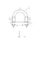
- FIG. 1 is a diagram showing a configuration example of a U-bolt 10 according to the first embodiment of the present disclosure.
- the U-bolt 10 includes a pair of shaft portions 11A and 11B, a bridge portion 12, and a photonic crystal thin film (hereinafter referred to as “PhC thin film”) 14. and
- the shaft portions 11A and 11B are aligned in a predetermined direction and extend in a direction orthogonal to the predetermined direction.
- the direction in which the shaft portions 11A and 11B are arranged side by side is referred to as the X-axis direction (first direction)
- the direction in which the shaft portions 11A and 11B extend is referred to as the X-axis direction.
- a direction perpendicular to the X-axis direction and the Y-axis direction is referred to as a Z-axis direction (third direction).
- the axial part 11A and the axial part 11B it is called the axial part 11.
- the shaft portion 11A and the shaft portion 11B are collectively referred to as a pair of shaft portions 11. As shown in FIG.
- the bridge portion 12 connects one end of each of the shaft portions 11A and 11B.
- the bridge portion 12 can be curved in a semicircular shape, and the bridge portion 12 connects one end of each of the shaft portions 11A and 11B, so that the U-bolt 10 forms a U-shape.
- the shaft portion 11A and the shaft portion 11B have a screw portion 13 having a screw thread structure on the other end side thereof.
- a fastener 1 such as piping is arranged inside the U-shaped U-bolt 10 (the space surrounded by the pair of shaft portions 11 and the bridge portion 12).
- a shaft portion 11A and a shaft portion are inserted into a pair of through holes 4A and 4B provided in the object to be fastened 2 such as a supporting metal fitting from one surface side of the object to be fastened 2, respectively.
- 11B is inserted.
- Nuts 3A and 3B having a thread structure that engages with the thread structure of the threaded portion 13 are tightened on the threaded portions 13 of the shaft portions 11A and 11B that protrude from the other side of the fastened object 2, respectively.
- the shaft portion 11 is tightened by the nut 3 .
- the U-bolt 10 is fastened to the object 2 to be fastened, and the object 1 is sandwiched and fixed between the U-bolt 10 and the object 2 to be fastened.
- the nuts 3A and 3B are referred to as nuts 3 when not distinguished from each other.
- the through-hole 4A and the through-hole 4B are referred to as the through-hole 4 when not distinguished from each other.
- the PhC thin film 14 is attached to at least part of at least one of the pair of shafts 11 .
- the PhC thin film 14 is attached to the entire one shaft portion 11A, but it is not limited to this.
- the PhC thin film 14 may be attached to a portion of one shaft 11A.
- the PhC thin film 14 may be attached to a part of the outer edge of the cross section perpendicular to the axis of the shaft part 11, or may be attached to a part in the direction in which the axis of the shaft part 11 extends. may be
- the PhC thin film 14 has shaft portions 11A and 11B inserted into a pair of through holes 4A and 4B provided in the object 2 to be fastened, and the U-bolt 10 and one surface of the object 2 to be fastened.
- the fastening object 1 is sandwiched and fixed between the positions of one surface of the object to be fastened 2 (position a) and the position of the boundary between the shaft portion 11 and the bridge portion 12 (position b).
- the PhC thin film 14 is a thin film made up of photonic crystals (PhC).
- the PhC thin film 14 may be a collection of particles, such as an opal thin film, or a single or multi-layer thin film composed of polymer or glass.
- the PhC thin film 14 may be a thin film using a semiconductor process (etching) or a thin film produced by a micro 3D printer.
- the PhC thin film 14 changes color according to the strain of the PhC thin film 14 . Further, the PhC thin film 14 is strained according to the strain of at least a part of the shaft portion 11 to which the PhC thin film 14 is attached. Therefore, the PhC thin film 14 changes color according to the strain of at least a part of the shaft portion 11 to which the PhC thin film 14 is attached.
- the PhC thin film 14 is generated by adjusting the fine particle diameter and the inter-particle distance, and the color characteristics indicating the relationship between the strain of the PhC thin film 14 and the color of the PhC thin film 14 in which the strain is generated are uniquely determined. ing.
- the PhC thin film 14 has a fine particle diameter and particle It may be generated by adjusting the inter-distance.
- the PhC thin film 14 may be produced by adjusting the fine particle diameter and the inter-particle distance according to the design concept (tightening in the elastic region, tightening in the plastic region). Thereby, the operator can recognize the distortion of the portion of the U-bolt 10 to which the PhC thin film 14 is attached based on the color of the PhC thin film 14 . Therefore, the operator can tighten the shaft portion 11 with the nut 3 so as to generate a strain corresponding to the target axial force acting on the U bolt 10, thereby properly fastening the U bolt 10. .
- the PhC thin film 14 may be attached by coating, may be attached by bonding, or may be attached by any other method. Note that the scale of the PhC thin film 14 in FIG. 1 is not necessarily the same as the actual scale. The same applies to FIGS. 2 to 4 as well.
- the PhC thin film 14 may be attached only to the shaft portion 11B.
- the PhC thin film 14 may be attached to both the shaft portion 11A and the shaft portion 11B.
- the PhC thin film 14 is attached to the entirety of both the shaft portion 11A and the shaft portion 11B.
- the PhC thin film 14 may be attached to a part of both the shaft portion 11A and the shaft portion 11B.
- FIGS. 5A and 5B are diagrams showing a state in which the U-bolt 10 shown in FIG. 4 is fastened to the object 2 to be fastened.
- FIG. 5A is a diagram showing the tensile force acting on the U-bolt 10 when the axial forces acting on the shaft portions 11A and 11B are uniform.
- FIG. 5B is a diagram showing the tensile force and compressive force acting on the U-bolt 10 when the axial forces acting on the shaft portions 11A and 11B are uneven.
- FIG. 6 is a diagram illustrating an example hardware configuration of the detection device 20 according to an embodiment of the present disclosure.
- FIG. 6 shows an example of the hardware configuration of the detection device 20 when the detection device 20 is configured by a computer capable of executing program instructions.
- the computer may be a general-purpose computer, a dedicated computer, a workstation, a PC (Personal Computer), an electronic notepad, a smart phone, or the like.
- Program instructions may be program code, code segments, etc. for performing the required tasks.
- the detection device 20 is a smartphone, the worker can easily carry the detection device 20 to the place where the U-bolt 10 is fastened to the object to be fastened 2 during installation or inspection of the U-bolt 10, which is convenient. be improved.
- the detection device 20 includes a processor 110, a ROM (Read Only Memory) 120, a RAM (Random Access Memory) 130, a storage 140, an input unit 150, a display unit 160 and a communication interface (I / F) 170 have Each component is communicatively connected to each other via a bus 190 .
- the processor 110 is specifically a CPU (Central Processing Unit), MPU (Micro Processing Unit), GPU (Graphics Processing Unit), DSP (Digital Signal Processor), SoC (System on a Chip) or the like. may be configured by a plurality of processors of
- the processor 110 controls each component and executes various arithmetic processes. That is, processor 110 reads a program from ROM 120 or storage 140 and executes the program using RAM 130 as a work area. The processor 110 performs control of each configuration and various arithmetic processes according to programs stored in the ROM 120 storage 140 . In this embodiment, the ROM 120 or storage 140 stores a program according to the present disclosure.
- Programs are stored in non-transitory storage media such as CD-ROM (Compact Disk Read Only Memory), DVD-ROM (Digital Versatile Disk Read Only Memory), USB (Universal Serial Bus) memory, etc. may be provided in Also, the program may be downloaded from an external device via a network.
- CD-ROM Compact Disk Read Only Memory
- DVD-ROM Digital Versatile Disk Read Only Memory
- USB Universal Serial Bus
- the ROM 120 stores various programs and various data.
- RAM 130 temporarily stores programs or data as a work area.
- the storage 140 is configured by a HDD (Hard Disk Drive) or SSD (Solid State Drive) and stores various programs including an operating system and various data.
- the input unit 150 includes a pointing device such as a mouse and a keyboard, and is used for various inputs.
- the display unit 160 is, for example, a liquid crystal display, and displays various information.
- the display unit 160 may employ a touch panel method and function as the input unit 150 .
- the communication interface 170 is an interface for communicating with other devices such as external devices (not shown), and uses standards such as Ethernet (registered trademark), FDDI, and Wi-Fi (registered trademark), for example.
- FIG. 7 is a diagram showing an example of the functional configuration of the detection device 20 according to the present disclosure.
- the detection device 20 according to the present disclosure detects the tightening state of the shaft portion 11 of the U-bolt 10 by the nut 3 and outputs tightening information regarding the tightening.
- the detection device 20 includes an imaging unit 21, a color characteristic storage unit 22, a detection unit 23, a detection result storage unit 24, and an output unit 25.
- the imaging unit 21 is configured by a camera.
- the color characteristic storage unit 22 and the detection result storage unit 24 are configured by the RAM 130 or the storage 140, for example.
- the detection unit 23 constitutes a control unit (controller).
- the control unit may be composed of dedicated hardware such as ASIC (Application Specific Integrated Circuit) or FPGA (Field-Programmable Gate Array), or may be composed of a processor, or may be composed of both. good too.
- the output unit 25 may include the display unit 160, for example.
- the imaging unit 21 generates an observation image by imaging at least a portion of at least one of the pair of shaft portions 11 to which the PhC thin film 14 is attached.
- an observation area is defined as an observation area in which an image of at least a part of at least one of the pair of shafts 11 to which the PhC thin film 14 is attached is shown.
- the color characteristic storage unit 22 stores color characteristics indicating the relationship between the strain ⁇ of the PhC thin film 14 and the color of the PhC thin film 14 in which the strain ⁇ is generated.
- the colors stored in the color characteristic storage unit 22 are indicated by RGB values, for example.
- the detection unit 23 detects the strain ⁇ of at least a portion of the shaft portion 11 to which the PhC thin film 14 is attached, based on the observation area in the observation image generated by the imaging unit 21 . Specifically, the detection unit 23 detects a representative value of pixels forming an observation area in the observation image.
- the representative value is, for example, a value related to the RGB values of the pixels forming the observation area, and can be, for example, the average value, median value, maximum value, or minimum value of each of the R value, G value, and B value. .
- the detection unit 23 detects the distortion ⁇ stored in the color characteristic storage unit 22 corresponding to the representative values indicated by the RGB values.
- the detection unit 23 can detect the target difference ⁇ 1 , which is the difference between the strain ⁇ and the target strain ⁇ T . In this case, the detection unit 23 can further detect whether or not the absolute value of the target difference ⁇ 1 is less than a predetermined threshold.
- the target strain ⁇ T is the strain ⁇ generated in the shaft portion 11 on which the target axial force described above is acting.
- the detector 23 detects both the shafts 11A and 11B. A first representative value and a second representative value based on the colors of the pixels forming each of the observation regions are detected. Based on the first representative value and the second representative value, the detection unit 23 can detect the strain ⁇ A and the strain ⁇ B of both the shaft portions 11A and 11B, respectively.
- the detection unit 23 can detect the target differences ⁇ 1A and ⁇ 1B , which are the differences between the strains ⁇ A and ⁇ B , respectively , and the target strain ⁇ T as the target differences ⁇ 1 . In this case, the detection unit 23 can further detect whether or not the absolute values of the target differences ⁇ 1A and ⁇ 1B are less than a predetermined threshold.
- the detection unit 23 can detect the relative difference ⁇ 2 , which is the difference between the strain ⁇ A and the strain ⁇ B . In this case, the detection unit 23 can further detect whether the absolute value of the relative difference ⁇ 2 is less than a predetermined threshold.
- the tightening information can include at least one or more of strain ⁇ , target difference ⁇ 1 , target difference index, relative difference ⁇ 2 , relative difference index.
- the target difference index is information indicating whether or not the absolute value of the target difference ⁇ 1 is less than a predetermined threshold.
- the relative difference index is information indicating whether the absolute value of the relative difference ⁇ 2 is less than a predetermined threshold.
- the tightening information is information indicating that the U-bolt 10 has been tightened instead of the target difference index. may contain. Further, when the detection unit 23 determines that the absolute value of the target difference ⁇ 1 is equal to or greater than the predetermined threshold value, the tightening information indicates that the U-bolt 10 has not been completely tightened instead of the target difference index. May contain information.
- the tightening information indicates that the shaft portions 11A and 11B are substantially evenly tightened instead of the relative difference index. may include information indicating that Further, when the detection unit 23 determines that the absolute value of the relative difference ⁇ 2 is equal to or greater than the predetermined threshold value, the tightening information indicates that the shaft portions 11A and 11B are substantially evenly tightened instead of the relative difference index. may include information indicating that it is not
- the detection result storage unit 24 stores tightening information detected by the detection unit 23 . By doing so, for example, it is possible to leave a trail of completion of normal construction (fastening of the U-bolt 10).
- the output unit 25 outputs tightening information regarding tightening of the shaft portion 11 of the U-bolt 10 by the nut 3 based on the strain ⁇ detected by the detection unit 23 .
- FIG. 8 is a flow chart showing an example of the operation for fastening the U-bolt 10 according to the first embodiment.
- the operation for fastening the U-bolt 10 described with reference to FIG. 8 corresponds to the construction method for fastening the U-bolt 10 according to the first embodiment.
- step S11 the operator passes the shaft portions 11A and 11B of the U-bolt 10 through the through holes 4A and 4B, respectively.
- step S12 the operator tightens the shafts 11A and 11B with the nuts 3A and 3B, respectively.
- step S13 the imaging unit 21 of the detection device 20 generates an observation image of at least part of at least one of the pair of shafts 11 to which the PhC thin film 14 is attached.
- the detection unit 23 detects the strain ⁇ of at least one of the shaft portions 11A and 11B to which the PhC thin film 14 is attached based on the observation area in the observation image generated by the imaging unit 21. Specifically, the detection unit 23 detects a representative value based on the color of the pixels forming the observation area in the observation image. Then, the detection unit 23 detects the strain ⁇ stored in the color characteristic storage unit 22 corresponding to the representative value. The detection unit 23 may detect the target difference ⁇ 1 based on the strain ⁇ . The detection unit 23 may determine whether or not the absolute value of the target difference ⁇ 1 is less than a predetermined threshold.
- the detection unit 23 may detect the strain ⁇ of one of the shaft portions 11A and 11B.
- the detector 23 may detect the strain ⁇ of both the shaft portions 11A and 11B.
- the detection unit 23 may detect the relative difference ⁇ 2 when detecting the strain ⁇ of both the shaft portions 11A and 11B.
- the detection unit 23 may determine whether the absolute value of the relative difference ⁇ 2 is less than a predetermined threshold.
- step S15 the output unit 25 outputs the tightening information detected by the detection unit 23.
- step S16 the operator determines whether or not the fastening process has been completed based on the fastening information.
- the operator may determine that the fastening process has been completed. In this case, if the strain ⁇ is not within a predetermined range from the target strain ⁇ T , the operator determines that the fastening process has not been completed.
- the operator may determine that the fastening process has been completed. In this case, if the absolute value of the target difference ⁇ 1 is greater than or equal to a predetermined threshold value, the operator may determine that the fastening process has not been completed.
- the operator may determine that the fastening process is completed. good. In this case, if the target difference index indicates that the absolute value of the target difference ⁇ 1 is greater than or equal to a predetermined threshold value, the operator may determine that the fastening process is not completed.
- step S16 If it is determined in step S16 that the fastening process has been completed, this fastening process ends. If it is determined in step S16 that the fastening process has not been completed, in step S17 the operator changes the tightening of the shaft portion 11 based on the tightening information.
- step S17 When the tightening of the shaft portion 11 is changed in step S17, the process returns to step S13 to repeat the process.
- the operator may change the tightening of one of the shaft portions 11A and 11B based on the tightening information, or may change the tightening of both the shaft portions 11A and 11B. You can change the tightening.
- the operator changes the tightening of the shaft portion 11A or the shaft portion 11B so that the relative difference ⁇ 2 becomes smaller, and then the relative difference ⁇ 2 becomes The tightening of the shaft portion 11A and the shaft portion 11 may be further changed so that the target difference ⁇ 1 becomes smaller while maintaining the state of being less than the predetermined threshold.
- the U-bolt 10 is attached to at least a portion of at least one of the pair of shafts 11, and A PhC thin film 14 that changes color is provided.
- the shaft portion 11 can be tightened by the nut 3 so that the strain ⁇ of the shaft portion 11 becomes the target strain ⁇ T , that is, the target axial force acts on the shaft portion 11 . Therefore, the operator can fasten the U-bolt 10 to the object 2 to be fastened with high accuracy, and accordingly can firmly fix the object 1 to be fastened.
- the pair of shaft portions 11A and 11B are inserted into the pair of through holes 4A and 4B provided in the object to be fastened 2, and the U-bolt 10 and one surface of the object to be fastened 2 are inserted. and the PhC thin film 14 is located between one surface of the object to be fastened 2 and the boundary between the shaft portion 11 and the bridge portion 12 on at least one shaft portion 11. .
- the PhC thin film 14 is attached to the shaft portion 11A and the shaft portion 11B. It is located between the boundary between the section 11 and the bridge section 12 .
- the operator can work so as not to increase the color difference between the PhC thin films 14 attached to the shaft portions 11A and 11B. can. Therefore, the operator can tighten the shaft portion 11 with the nut 3 , thereby appropriately fastening the U-bolt 10 to the fastened object 2 .
- the detection device 20 outputs tightening information based on the target difference ⁇ 1 . Therefore, the operator can tighten the shaft portion 11 with the nut 3 so that the strain ⁇ generated in the U-bolt 10 becomes the target strain ⁇ T , that is, the target axial force acts on the U-bolt 10. . Therefore, the operator can fasten the U-bolt 10 to the object 2 to be fastened with high accuracy, and accordingly can firmly fix the object 1 to be fastened.
- the detection device 20 outputs tightening information based on the relative difference ⁇ 2 .
- the strain ⁇ A of the shaft portion 11A and the strain ⁇ B of the shaft portion 11B are approximately the same not only when the fastening is completed but also during the work until the fastening is completed.
- the status quo must be maintained.
- the operator needs not only to set the strain ⁇ A and the strain ⁇ B as the target strain ⁇ T , but also to reduce the relative difference ⁇ 2 , which is the difference between the strain ⁇ A and the strain ⁇ B , during the work. be.
- the detection device 20 outputs the tightening information based on the relative difference ⁇ 2 , so that the operator can recognize the relative difference ⁇ 2 during the fastening work.
- the shank 11 can be tightened by the nut 3 . Therefore, the operator can fasten the U-bolt 10 to the object 2 to be fastened with high accuracy, and accordingly can firmly fix the object 1 to be fastened.
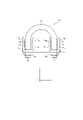
- FIG. 9 is a diagram showing an example configuration of a U-bolt 10A according to the second embodiment of the present disclosure.
- 10 is a cross-sectional view taken along the XY plane including the central axis of the U-bolt 10A shown in FIG. 9 and 10, the same components as in FIG. 4 are denoted by the same reference numerals, and descriptions thereof are omitted.
- the U-bolt 10A according to this embodiment further includes a reference thin film 15 as compared with the U-bolt 10 according to the first embodiment.
- the scale of the PhC thin film 14 and the reference thin film 15 in FIGS. 9 and 10 is not necessarily the same as the actual scale.
- the reference thin film 15 is attached to at least a portion of the U-bolt 10A that is different from the portion to which the PhC thin film 14 is attached, does not discolor in response to strain, and prevents the target axial force from being applied to the shaft portion 11. A coating with the color of the PhC thin film 14 as it works.
- the reference thin film 15 is attached to the portion of the bridge portion 12 adjacent to the portion to which the PhC thin film 14 is attached.
- the operator who tightens the U bolt 10A can easily visually recognize the colors of the PhC thin film 14 and the reference thin film 15 without moving the line of sight.
- the reference thin film 15 may be attached by coating, may be attached by adhesion, or may be attached by any other method. .
- the reference thin film 15 is attached adjacent to the PhC thin film 14, but is not limited to this and may be attached without being adjacent to the PhC thin film 14.
- the reference thin film 15 is attached over the entire outer edge of the cross section perpendicular to the axis of the U-bolt 10A, but it may be attached to a part of the outer edge.
- the PhC thin film 14 is attached to the entire shaft portion 11 and the reference thin film 15 is attached to a portion of the bridge portion 12, but this is not the only option.
- the PhC thin film 14 may be attached to a portion of the shaft portion 11 and the reference thin film 15 may be attached to a portion of the shaft portion 11 to which the PhC thin film 14 is not attached.
- FIG. 11 is a flow chart showing an example of the operation for fastening the U-bolt 10A according to the second embodiment.
- the operation for fastening the U-bolt 10A described with reference to FIG. 11 corresponds to the construction method for fastening the U-bolt 10A according to the second embodiment.
- step S21 the operator passes the shaft portions 11A and 11 of the U-bolt 10A through the through holes 4A and 4B, respectively.
- step S22 the operator tightens the shafts 11A and 11B with the nuts 3A and 3B, respectively.
- step S23 the operator visually recognizes the color of the PhC thin film 14.
- step S24 the operator determines whether or not the fastening process is completed based on the color of the PhC thin film 14. Specifically, the operator determines whether or not the color of the PhC thin film 14 and the color of the reference thin film 15 are substantially the same. When the operator determines that the color of the PhC thin film 14 and the color of the reference thin film 15 are substantially the same, it is determined that the fastening process is completed. If the operator determines that the color of the PhC thin film 14 and the color of the reference thin film 15 are not substantially the same, the fastening process is not completed.
- step S24 If it is determined in step S24 that the fastening process is completed, this fastening process ends.
- step S25 the operator changes the tightening of the shaft portion 11 based on the tightening information. At this time, the operator may change the tightening of one of the shaft portions 11A and 11B based on the degree of similarity between the color of the PhC thin film 14 and the color of the reference thin film 15, or The tightening of both 11A and shaft portion 11B may be changed.
- step S25 When the tightening of the shaft portion 11 is changed in step S25, the process returns to step S23 to repeat the process.
- the operator selects the shaft portion 11A or the shaft portion 11A or the shaft portion 11B so that the color of the PhC thin film 14 attached to each of the shaft portions 11A and 11B becomes high.
- the tightening of shank 11A and shank 11 may be further changed so that the degree of similarity between the color of PhC thin film 14 and the color of reference thin film 15 is increased.
- the U-bolt 10A is attached to at least a portion of a portion different from the portion to which the PhC thin film 14 is attached, and the reference thin film 15 that does not discolor according to strain is attached. Prepare more.
- the operator works by comparing the color of the PhC membrane 14 to his stored color corresponding to the target strain ⁇ T . Therefore, it may be difficult to fasten the U-bolt 10A to the fastened object 2 so that the strain ⁇ of the shaft portion 11 becomes the target strain ⁇ T .
- the PhC thin film 14 when fastening the U-bolt 10A so that the color of the PhC thin film 14 is substantially the same as the color corresponding to the target strain ⁇ T , the PhC thin film 14 is By comparing the color with the color of the reference thin film 15, which is the color corresponding to the target strain ⁇ T , the shaft 11 can be tightened by the nut 3 so that the target strain ⁇ T is generated in the shaft 11. . Therefore, the operator can fasten the U-bolt 10A to the object 2 to be fastened with high accuracy, thereby firmly fixing the object 1 to be fastened.
- the operator can appropriately recognize the distortion of the U bolt 10A by visual inspection, it is possible to easily check whether the U bolt 10A is properly tightened during construction and inspection. be able to. In particular, in an environment such as a high place where it is difficult to confirm the strain ⁇ of the U-bolt 10A by palpation, it is possible for the operator to greatly save the trouble of approaching the environment.
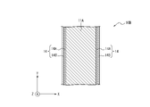
- ⁇ Third Embodiment> (Configuration of U bolt) 12A and 12B are cross-sectional views showing examples of a portion of a U-bolt 10B according to the third embodiment of the present disclosure.
- FIGS. 12A and 12B the same reference numerals are assigned to the same configurations as in FIG. 4, and the description thereof is omitted.
- the PhC thin film 14 included in the U bolt 10B is different from the PhC thin film 14 included in the U bolt 10 according to the first embodiment, and as shown in FIGS. and the PhC thin film 14B.
- the PhC thin films 14A and 14B are laminated on the surface of the shaft portion 11 of the U-bolt 10B in the radial direction of the shaft portion 11 .
- the PhC thin films 14A and the PhC thin films 14B are alternately arranged on the surface of the shaft portion 11 of the U-bolt 10B in the axial direction of the shaft portion 11, as shown in FIG. 12B. Note that the scale of the PhC thin films 14A and 14B in FIGS.
- the PhC thin film 14A and the PhC thin film 14B in FIG. 12B are large enough to be visually recognized by the human eye as the colors of the PhC thin film 14A and the PhC thin film 14B are mixed.
- the PhC thin film 14 is composed of a plurality of PhC thin films 14A and PhC thin films 14B having different color characteristics.
- the strain ⁇ is in the first range, the first color obtained by mixing the colors of the plurality of PhC thin films 14A and the PhC thin films 14B, and when the strain ⁇ is in the second range, the plurality of PhC thin films 14A and The difference between the respective colors of the PhC thin film 14B and the second mixed color is the third color of the PhC thin film 14A when the strain ⁇ is in the first range and the strain ⁇ is in the second range. It is larger than the difference from the fourth color of the PhC thin film 14A at that time. The same can be said for the difference (color difference) between the color when the strain ⁇ is in the second range and the color when the strain ⁇ is in the third range.
- the plurality of PhC thin films 14A and PhC thin films 14B may develop colors by reflecting visible light different from each other.
- the strain ⁇ is in a second range different from the first range
- the PhC thin film 14A develops color by reflecting visible light
- the PhC thin film 14B develops color by reflecting light having a wavelength outside the visible light region. It does not have to be colored.
- the colors of the PhC thin films 14 including the PhC thin films 14A and 14B will be described in more detail with reference to FIGS. 13A to 13C.
- the PhC thin film 14A reflects light having a wavelength of 640-770 nm when no axial force is generated (when the strain ⁇ is in the first range). That is, the PhC thin film 14A turns red when no axial force is generated. Further, as shown by the dashed line in FIG. 13B, the PhC thin film 14A has a wavelength of 590 to 640 nm when the axial force is greater than 0 and less than the intermediate axial force (when the strain ⁇ is in the second range). reflect. That is, the PhC thin film 14A turns orange when the axial force is greater than 0 and less than the intermediate axial force.
- the intermediate axial force is an axial force that is smaller than the target axial force generated when the U-bolt 10B is completely tightened, and is, for example, an axial force that is 50% of the target axial force. can be done.
- the PhC thin film 14A has a wavelength of 490 to 550 nm when the axial force is more than the intermediate axial force and less than the target axial force (when the strain ⁇ is in the third range). Reflects light with That is, the PhC thin film 14A turns green when the axial force is greater than or equal to the intermediate axial force and less than the target axial force.
- the PhC thin film 14B reflects light having a wavelength of 490-550 nm when no axial force is generated. That is, the PhC thin film 14B turns green when no axial force is generated.
- the PhC thin film 14A reflects light having a wavelength of 315-400 nm when the axial force is greater than 0 and less than the intermediate axial force. That is, the PhC thin film 14B does not produce any color perceivable by humans when the axial force is greater than 0 and less than the intermediate axial force.
- the PhC thin film 14B reflects light having a wavelength of 280 to 315 nm when the axial force is equal to or greater than the intermediate axial force and less than the target axial force. That is, the PhC thin film 14B does not produce a color that can be perceived by humans when the axial force is greater than or equal to the intermediate axial force and less than the target axial force.
- the PhC thin film 14 composed of the PhC thin film 14A and the PhC thin film 14B, when no axial force is generated (when the strain ⁇ is in the first range), is perceived by human eyes as red and green. It is visually recognized as purple, which is a mixed color. Further, the PhC thin film 14 is visually recognized orange by human eyes when the axial force is greater than 0 and less than the intermediate axial force (when the strain ⁇ is in the second range). The PhC thin film 14 appears green to the human eye when the axial force is greater than or equal to the intermediate axial force and less than the target axial force.
- the wavelength of light reflected by the PhC thin film 14 becomes shorter as the axial force increases. That is, the color of the PhC thin film 14 changes in order of red, orange, and green. In this case, it may be difficult for the human eye to distinguish between red and orange.
- the PhC thin film 14 is composed of two PhC thin films 14A and 14A, the colors of the PhC thin film 14 are purple, orange, and green in this order as described above. Change. Since the human eye can easily distinguish between purple and orange compared to red and orange, the operator can easily recognize the change in the axial force.
- the PhC thin film 14 is composed of the two PhC thin films 14A and 14B, but is not limited thereto, and may be composed of three or more PhC thin films 14 having different color characteristics. good too.
- the hardware configuration of the detection device 20 according to the third embodiment is the same as the hardware configuration of the detection device 20 according to the first embodiment.
- a functional configuration of the detection device 20 according to the third embodiment is the same as that of the detection device 20 according to the first embodiment.
- the construction method for mounting the U bolts 10B according to the third embodiment is the same as the construction method for mounting the U bolts 10 according to the first embodiment.
- the PhC thin film 14 is composed of a plurality of PhC thin films 14 having different color characteristics. Then, when the strain ⁇ is in the first range, the first color obtained by mixing the colors of the plurality of PhC thin films 14, and when the strain ⁇ is in the second range, the colors of the plurality of PhC thin films 14 The difference between the second color mixed with is the third color of one PhC thin film 14 of the plurality of PhC thin films 14 when the strain ⁇ is in the first range, and the third color of the PhC thin film 14 when the strain ⁇ is in the first range. is greater than the difference from the fourth color of one PhC thin film 14 when in the range of .
- the operator can clearly identify the color of the PhC thin film 14 corresponding to the strain ⁇ , and can appropriately tighten the shaft portion 11 to the nut 3 . Therefore, the operator can fasten the U-bolt 10B to the object 2 to be fastened with high accuracy, thereby firmly fixing the object 1 to be fastened.
- the U-bolt 10B includes the PhC thin film 14 as described above, so the detection device 20 can measure the strain ⁇ of the shaft portion 11 with higher accuracy. Thereby, the operator can tighten the shaft portion 11 with the nut 3 using the tightening information output based on the strain ⁇ measured with high accuracy by the detection device 20 . Therefore, the operator can fasten the U-bolt 10B to the object 2 to be fastened with high accuracy, thereby firmly fixing the object 1 to be fastened.
- a computer can be preferably used to function as each part of the detection device 20 described above.
- Such a computer is realized by storing a program describing the processing details for realizing the function of each part of the detection device 20 in the memory of the computer, and reading and executing the program by the processor of the computer. be able to. That is, the program can cause the computer to function as the detection device 20 described above. It is also possible to store the program in a non-temporary storage medium. It is also possible to provide the program via a network.
Landscapes
- Engineering & Computer Science (AREA)
- General Engineering & Computer Science (AREA)
- Physics & Mathematics (AREA)
- General Physics & Mathematics (AREA)
- Mechanical Engineering (AREA)
- Force Measurement Appropriate To Specific Purposes (AREA)
Priority Applications (3)
| Application Number | Priority Date | Filing Date | Title |
|---|---|---|---|
| JP2022577970A JP7583301B2 (ja) | 2021-01-29 | 2021-01-29 | Uボルト、施工方法及び検出装置 |
| PCT/JP2021/003352 WO2022162897A1 (ja) | 2021-01-29 | 2021-01-29 | Uボルト、施工方法及び検出装置 |
| US18/274,497 US20240093807A1 (en) | 2021-01-29 | 2021-01-29 | U-bolt, construction method, and detection device |
Applications Claiming Priority (1)
| Application Number | Priority Date | Filing Date | Title |
|---|---|---|---|
| PCT/JP2021/003352 WO2022162897A1 (ja) | 2021-01-29 | 2021-01-29 | Uボルト、施工方法及び検出装置 |
Publications (1)
| Publication Number | Publication Date |
|---|---|
| WO2022162897A1 true WO2022162897A1 (ja) | 2022-08-04 |
Family
ID=82654352
Family Applications (1)
| Application Number | Title | Priority Date | Filing Date |
|---|---|---|---|
| PCT/JP2021/003352 Ceased WO2022162897A1 (ja) | 2021-01-29 | 2021-01-29 | Uボルト、施工方法及び検出装置 |
Country Status (3)
| Country | Link |
|---|---|
| US (1) | US20240093807A1 (https=) |
| JP (1) | JP7583301B2 (https=) |
| WO (1) | WO2022162897A1 (https=) |
Families Citing this family (1)
| Publication number | Priority date | Publication date | Assignee | Title |
|---|---|---|---|---|
| WO2022157961A1 (ja) * | 2021-01-25 | 2022-07-28 | 日本電信電話株式会社 | Uボルト及び施工方法 |
Citations (3)
| Publication number | Priority date | Publication date | Assignee | Title |
|---|---|---|---|---|
| US5804737A (en) * | 1997-08-29 | 1998-09-08 | Mccoy Bolt Works, Inc. | U-bolt testing apparatus |
| JP2014112082A (ja) * | 2012-10-23 | 2014-06-19 | Boeing Co | 光ファイバ結合のフォトニック結晶スラブひずみセンサ、システムならびに製造および使用の方法 |
| US20180041011A1 (en) * | 2016-08-03 | 2018-02-08 | Korea University Research And Business Foundation | Photonic crystal laser and strain measuring device |
Family Cites Families (3)
| Publication number | Priority date | Publication date | Assignee | Title |
|---|---|---|---|---|
| US20040053417A1 (en) * | 2002-09-14 | 2004-03-18 | Sinsky Jerome L. | Diagnostic device and method of using same |
| JP4998811B2 (ja) * | 2010-09-27 | 2012-08-15 | 株式会社恵信工業 | 脆性破壊するトルク感応表示体。 |
| US8540468B2 (en) * | 2011-09-13 | 2013-09-24 | King Fahd University Of Petroleum And Minerals | Smart lid for smart bolts and probes |
-
2021
- 2021-01-29 WO PCT/JP2021/003352 patent/WO2022162897A1/ja not_active Ceased
- 2021-01-29 JP JP2022577970A patent/JP7583301B2/ja active Active
- 2021-01-29 US US18/274,497 patent/US20240093807A1/en active Pending
Patent Citations (3)
| Publication number | Priority date | Publication date | Assignee | Title |
|---|---|---|---|---|
| US5804737A (en) * | 1997-08-29 | 1998-09-08 | Mccoy Bolt Works, Inc. | U-bolt testing apparatus |
| JP2014112082A (ja) * | 2012-10-23 | 2014-06-19 | Boeing Co | 光ファイバ結合のフォトニック結晶スラブひずみセンサ、システムならびに製造および使用の方法 |
| US20180041011A1 (en) * | 2016-08-03 | 2018-02-08 | Korea University Research And Business Foundation | Photonic crystal laser and strain measuring device |
Also Published As
| Publication number | Publication date |
|---|---|
| JP7583301B2 (ja) | 2024-11-14 |
| JPWO2022162897A1 (https=) | 2022-08-04 |
| US20240093807A1 (en) | 2024-03-21 |
Similar Documents
| Publication | Publication Date | Title |
|---|---|---|
| JP6954368B2 (ja) | 変位成分検出装置、変位成分検出方法、及びプログラム | |
| US7509872B2 (en) | Stress and strain analysis method and its equipment | |
| JPWO2016152076A1 (ja) | 構造物の状態判定装置と状態判定システムおよび状態判定方法 | |
| JP7405788B2 (ja) | ボルト軸力検査方法及びボルト軸力検査装置 | |
| CN106457537A (zh) | 凸缘联接技巧判定装置及凸缘联接技巧判定程序 | |
| EP3039649B1 (en) | Method of analyzing deformations in a laminated object and according system | |
| JP2010117334A (ja) | ボルト軸力測定方法およびボルト軸力測定機 | |
| JP2019070641A (ja) | 冗長センサ欠陥検出 | |
| WO2022162897A1 (ja) | Uボルト、施工方法及び検出装置 | |
| KR101406970B1 (ko) | 구조물 안전 진단 방법 | |
| Ramesh | Photoelasticity | |
| KR101567549B1 (ko) | 토크인가공구 검사장치를 이용한 토크인가공구 관리시스템 | |
| Ficzere et al. | Validation of numerically simulated rapid-prototype model by photoelastic coating | |
| Gontarz et al. | Online monitoring of steel constructions using passive methods | |
| CN116563752A (zh) | 基于空间域和时间域特征拉索频率的视频检测方法及系统 | |
| US11365963B2 (en) | State determination apparatus, state determination method, and computer-readable recording medium | |
| WO2020158099A1 (ja) | 画像表示装置、画像表示システム、及び検査方法 | |
| JP7564468B2 (ja) | 施工方法及び検出装置 | |
| WO2022162899A1 (ja) | Uボルト、施工方法及び計測装置 | |
| CN107621322B (zh) | 传感器装置 | |
| CN104972423A (zh) | 螺栓紧固检测方法、装置、系统及液压扳手 | |
| JP2007187596A (ja) | 3軸力覚センサ | |
| CN101013152A (zh) | 用于确定传感器装置的故障传感器元件的电路和方法 | |
| JP2017129502A (ja) | 歪みセンサ、監視システム、及び歪みセンサの製造方法 | |
| JP2022139432A (ja) | ボルト軸力評価システム、ボルト軸力評価方法、およびボルト軸力評価プログラム |
Legal Events
| Date | Code | Title | Description |
|---|---|---|---|
| 121 | Ep: the epo has been informed by wipo that ep was designated in this application |
Ref document number: 21922912 Country of ref document: EP Kind code of ref document: A1 |
|
| ENP | Entry into the national phase |
Ref document number: 2022577970 Country of ref document: JP Kind code of ref document: A |
|
| WWE | Wipo information: entry into national phase |
Ref document number: 18274497 Country of ref document: US |
|
| NENP | Non-entry into the national phase |
Ref country code: DE |
|
| 122 | Ep: pct application non-entry in european phase |
Ref document number: 21922912 Country of ref document: EP Kind code of ref document: A1 |