WO2022158197A1 - リッド開閉構造 - Google Patents
リッド開閉構造 Download PDFInfo
- Publication number
- WO2022158197A1 WO2022158197A1 PCT/JP2021/046697 JP2021046697W WO2022158197A1 WO 2022158197 A1 WO2022158197 A1 WO 2022158197A1 JP 2021046697 W JP2021046697 W JP 2021046697W WO 2022158197 A1 WO2022158197 A1 WO 2022158197A1
- Authority
- WO
- WIPO (PCT)
- Prior art keywords
- lid
- power
- engaged
- opening
- engaging portion
- Prior art date
- Legal status (The legal status is an assumption and is not a legal conclusion. Google has not performed a legal analysis and makes no representation as to the accuracy of the status listed.)
- Ceased
Links
Images






Classifications
-
- B—PERFORMING OPERATIONS; TRANSPORTING
- B60—VEHICLES IN GENERAL
- B60K—ARRANGEMENT OR MOUNTING OF PROPULSION UNITS OR OF TRANSMISSIONS IN VEHICLES; ARRANGEMENT OR MOUNTING OF PLURAL DIVERSE PRIME-MOVERS IN VEHICLES; AUXILIARY DRIVES FOR VEHICLES; INSTRUMENTATION OR DASHBOARDS FOR VEHICLES; ARRANGEMENTS IN CONNECTION WITH COOLING, AIR INTAKE, GAS EXHAUST OR FUEL SUPPLY OF PROPULSION UNITS IN VEHICLES
- B60K15/00—Arrangement in connection with fuel supply of combustion engines or other fuel consuming energy converters, e.g. fuel cells; Mounting or construction of fuel tanks
- B60K15/03—Fuel tanks
- B60K15/04—Tank inlets
- B60K15/05—Inlet covers
-
- E—FIXED CONSTRUCTIONS
- E05—LOCKS; KEYS; WINDOW OR DOOR FITTINGS; SAFES
- E05B—LOCKS; ACCESSORIES THEREFOR; HANDCUFFS
- E05B83/00—Vehicle locks specially adapted for particular types of wing or vehicle
- E05B83/28—Locks for glove compartments, console boxes, fuel inlet covers or the like
- E05B83/34—Locks for glove compartments, console boxes, fuel inlet covers or the like for fuel inlet covers essentially flush with the vehicle surface
-
- B—PERFORMING OPERATIONS; TRANSPORTING
- B60—VEHICLES IN GENERAL
- B60K—ARRANGEMENT OR MOUNTING OF PROPULSION UNITS OR OF TRANSMISSIONS IN VEHICLES; ARRANGEMENT OR MOUNTING OF PLURAL DIVERSE PRIME-MOVERS IN VEHICLES; AUXILIARY DRIVES FOR VEHICLES; INSTRUMENTATION OR DASHBOARDS FOR VEHICLES; ARRANGEMENTS IN CONNECTION WITH COOLING, AIR INTAKE, GAS EXHAUST OR FUEL SUPPLY OF PROPULSION UNITS IN VEHICLES
- B60K15/00—Arrangement in connection with fuel supply of combustion engines or other fuel consuming energy converters, e.g. fuel cells; Mounting or construction of fuel tanks
- B60K15/03—Fuel tanks
- B60K15/04—Tank inlets
- B60K15/05—Inlet covers
- B60K2015/0561—Locking means for the inlet cover
- B60K2015/0584—Locking means for the inlet cover the locking bolt is linearly moved to lock or unlock
Definitions
- the present invention relates to a lid opening/closing structure capable of opening and closing a lid that closes an opening of a vehicle body base material, for example.
- Patent Document 1 a lid opening/closing structure that opens and closes a lid that closes an opening in a vehicle body base material provided with a charging port, a fuel filler port, etc.
- the lid opening/closing structure described in Patent Document 1 includes a locking member capable of locking the lid in a fully closed position, and an electric actuator that advances and retracts the locking member between a restricted position and a restricted position.
- the above-described lid opening/closing structure also includes an emergency operation member capable of retracting the lock member from the restricted position to the restricted position in an emergency such as when the electric actuator fails.
- the electric actuator described in Patent Document 1 is a device that advances and retracts a lock member that locks the lid in the fully closed position between the restricted position and the restricted position, and is not a device that opens and closes the lid itself. .
- a lid that can be opened and closed between a fully closed position and a fully opened position with respect to a substrate, and a first power that causes the lid to open and close with respect to the substrate is applied to the lid.
- a lid opening/closing structure comprising: a power applying mechanism; and a second power applying mechanism for applying a second power, different from the first power, to the lid for opening and closing the lid with respect to the base material by an external force operation.
- the second power applying mechanism has an engaging portion and an engaged portion that can be engaged with the engaging portion, and the engaging portion and the engaged portion are When the lid is opened and closed between the fully closed position and the fully opened position by the first power, the lids are not engaged with each other, while the second power is applied to the lid when the external force operation is performed.
- the lid opening/closing structure is such that the lid engages with each other so as to open and close the lid.
- the engaging portion and the engaged portion are engaged with each other, whereby the second power due to the external force is applied to the lid, and the lid is moved. It is opened and closed. Therefore, even if the lid cannot be opened/closed by the first power of the first power applying mechanism, the lid can be opened/closed by the second power of the second power applying mechanism.
- FIG. 2 is a front view of the lid opening/closing structure according to the first embodiment in a lid fully closed position
- FIG. 4 is a front view of the lid opening/closing structure of the first embodiment in a lid fully open position
- It is a perspective view of the principal part of lid opening-and-closing structure of a first embodiment. It is a front view of the important part of the lid opening and closing structure of the first embodiment.
- FIG. 5 is a cross-sectional view taken along line VV shown in FIG. 4
- FIG. 3 is an exploded view of the essential parts of the lid opening/closing structure of the first embodiment;
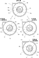
- FIG. 4 is a diagram showing the positional relationship of main parts during the opening/closing operation of the lid opening/closing structure of the first embodiment
- FIG. 11 is a perspective view of a main part of a lid opening/closing structure according to a second embodiment
- FIG. 10 is a front view of a main part of the lid opening/closing structure of the second embodiment
- FIG. 10 is a cross-sectional view taken along line XX shown in FIG. 9
- FIG. 10 is a cross-sectional view taken along line XI-XI shown in FIG. 9
- FIG. 10 is an exploded view of the essential parts of the lid opening/closing structure of the second embodiment
- FIG. 11 is a perspective view of a main part of a lid opening/closing structure according to a second embodiment
- FIG. 10 is a front view of a main part of the lid opening/closing structure of the second embodiment
- FIG. 10 is a cross-sectional view taken along line XX shown in FIG
- FIG. 11 is a perspective view of a main part of a lid opening/closing structure according to a third embodiment
- FIG. 11 is a perspective view of a wire used in the lid opening/closing structure of the third embodiment
- FIG. 11 is a cross-sectional view of a main part of the lid opening/closing structure of the third embodiment
- FIG. 10 is a diagram showing the positional relationship of the main parts during the opening/closing operation of the lid opening/closing structure of the third embodiment
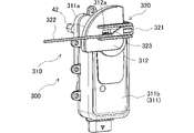
- FIG. 11 is a perspective view of a main part of a lid opening/closing structure according to a fourth embodiment
- It is a front view of the principal part of lid opening-and-closing structure of a fourth embodiment.
- FIG. 11 is an exploded view of the essential parts of the lid opening/closing structure of the fourth embodiment;
- FIG. 11 is a perspective view of a main part of a lid opening/closing structure according to a first modification;
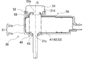
- FIG. 10 is a cross-sectional view of a main part of a lid opening/closing structure of a first modification;
- FIG. 11 is a perspective view of a main part of a lid opening/closing structure according to a second modification;
- FIG. 11 is a cross-sectional view of a main part of a lid opening/closing structure of a second modification;
- FIG. 1 Specific embodiments of the lid opening/closing structure according to the present invention will be described below with reference to FIGS. 1 to 24.
- FIG. 1 Specific embodiments of the lid opening/closing structure according to the present invention will be described below with reference to FIGS. 1 to 24.
- the lid opening/closing structure 1 of the first embodiment is a structure that opens and closes a lid 20 that closes an opening.
- the lid opening/closing structure 1 includes a base material 10, a lid 20, and a driving device 30, as shown in FIGS.
- the lid opening/closing structure 1 can open and close the lid 20 between a fully closed position and a fully opened position by rotating the lid 20 with respect to the base material 10 by the driving device 30 .
- the base material 10 is a container-like or box-like member. Specifically, the base material 10 is a tubular bottomed member having a bottom wall 11 formed on one end side (that is, the back side) and an opening 12 formed on the other end side (that is, the front side). is.
- the base material 10 is formed in a square tube shape or a cylindrical shape.
- the base material 10 is attached, for example, to an attachment hole provided in a side wall of a vehicle body, a bonnet, or the like.
- the mounting hole is provided with, for example, a charging port or a fuel port of the vehicle.
- the base material 10 is an injection molded body made of resin or the like.
- a bottom wall 11 of the base material 10 is provided with an outlet 13 having a predetermined shape.
- the outlet 13 communicates with the fuel supply port and charging port.
- One end of a pipe or cable connected to a fuel tank, a battery, or the like is exposed at the outlet 13 .
- One end of this pipe or cable is hidden inside the opening of the base material 10 at the closed position including the fully closed position of the lid 20, and is externally arranged so that fuel supply and charging are possible at the open position including the fully opened position of the lid 20. exposed to.
- the lid 20 is a plate-like member that closes the opening 12 of the base material 10 .
- the lid 20 is rotatably supported by the base material 10 .
- the lid 20 can be vertically rotated with respect to the base material 10 around a horizontally extending axis.
- the lid 20 can close the opening 12 and open the opening 12, and is opened and closed between a fully closed position and a fully open position.
- the lid 20 is an injection molded body made of resin, for example.
- the drive device 30 is a device that applies power to the lid 20 to open and close the lid 20 with respect to the base material 10 to open and close the lid 20 . 3, 4, 5 and 6, the driving device 30 has two power applying mechanisms 40, 50 for generating power respectively.
- the power applying mechanism 40 is referred to as the first power applying mechanism 40
- the power applying mechanism 50 is referred to as the second power applying mechanism 50, respectively.
- the power applied by the first power applying mechanism 40 is referred to as first power
- the power applied by the second power applying mechanism 50 is referred to as second power.
- the first power applying mechanism 40 has an electric actuator 41 and a rotating shaft 42 .
- the electric actuator 41 is a rotatable electric motor that generates the first power.
- the electric actuator 41 can rotate in both forward and reverse directions.
- the electric actuator 41 is rotationally driven in the forward direction according to an open command from the control device when the switch is opened by the operator. Further, the electric actuator 41 is rotationally driven in the reverse direction in accordance with a closing command from the control device when the switch closing operation is performed by the operator.
- the electric actuator 41 is housed inside the box member 31 of the driving device 30 .
- the box member 31 is composed of a lower box 31a and an upper box 31b.
- the electric actuator 41 is covered with a lower box 31a and an upper box 31b, and is accommodated in the box member 31 by fastening the lower box 31a and the upper box 31b.
- the rotating shaft 42 is a rotatable shaft member that applies the first power generated by the electric actuator 41 to the lid 20 .
- the rotary shaft 42 is rotatable around the axial center C. As shown in FIG.
- the rotating shaft 42 is interposed between the electric actuator 41 and the lid 20 .
- the rotary shaft 42 is axially fitted to the electric actuator 41 at one end in the axial direction, and rotates integrally with the rotation of the electric actuator 41 .
- the other end in the axial direction of the rotating shaft 42 protrudes axially outward from the through hole 31c of the lower box 31a of the box member 31 .
- the periphery of the through hole 31 c of the box member 31 is sealed with an O-ring 43 .
- the rotating shaft 42 is fitted to the lid 20 at the other end in the axial direction, and imparts to the lid 20 the first power generated by the electric actuator 41 by rotation. When the first power generated by the electric actuator 41 is applied to the lid 20, the lid 20 is opened and closed by the first power.
- the second power applying mechanism 50 has an emergency operation member 51, a wire 52, and a transmission member 53.
- the emergency operation member 51 is an operation member operated by an external force.
- the emergency operating member 51 is a rotatable disc-shaped arm member. A groove that opens radially outward is formed in the outer edge of the emergency operating member 51 .
- the emergency operation member 51 is rotatably housed in a housing portion 31d provided in the upper box 31b.
- the emergency operating member 51 is coaxial with the rotating shaft 42 and can rotate around the axis C. As shown in FIG.
- the emergency operation member 51 has a shaft 51a provided at the center of rotation and extending in the axial direction.
- the wire 52 is an external force applying portion that applies an external force to the emergency operation member 51.
- the wire 52 is wound along the groove on the outer edge of the emergency operating member 51 .
- One end of the wire 52 is attached and fixed at a predetermined position on the outer circumference of the emergency operating member 51, and the other end of the wire 52 is connected to an operating portion (not shown) such as a lever that is pulled by the operator.
- an operating portion such as a lever that is pulled by the operator.
- the transmission member 53 is a shaft member that transmits to the lid 20 via the rotating shaft 42 the external force generated by rotating the emergency operating member 51 as a second power different from the first power.
- the transmission member 53 is coaxial with the rotary shaft 42 and the shaft body 51 a of the emergency operation member 51 and is rotatable about the shaft center C. As shown in FIG. A shaft portion of the transmission member 53 is inserted into the box member 31 through a through hole of the upper box 31 b of the box member 31 . The periphery of the through-hole of the box member 31 is sealed with an O-ring 56 .
- One axial end of the transmission member 53 is axially fitted to the electric actuator 41 and connected to the rotating shaft 42 .
- the transmission member 53 rotates together with the rotation of the electric actuator 41 and the emergency operating member 51 .
- the transmission member 53 has a shaft hole 53a provided at the center of rotation and extending in the axial direction. A shaft 51a of the emergency operating member 51 is inserted into the shaft hole 53a.
- the second power applying mechanism 50 also has an engaging portion 54 and an engaged portion 55 that can be engaged with the engaging portion 54 .
- the engaging portion 54 is provided on the emergency operating member 51 .
- the engaged portion 55 is provided on the transmission member 53 .
- the emergency operation member 51 and the transmission member 53 are formed so that the engaging portion 54 and the engaged portion 55 engage with each other only at predetermined timings and do not engage with each other at other timings.
- the rotating shaft 42 is moved by the first power. When rotated, they do not engage each other.
- the emergency operation member 51 is rotationally operated by an external force from the wire 52
- the engaging portion 54 and the engaged portion 55 transmit the second power due to the external force to the lid 20 via the electric actuator 41.
- the lid 20 engages with each other such that the lid 20 opens and closes, that is, the rotary shaft 42 is rotated by the second power.
- the engaging portion 54 is formed on the shaft 51 a of the emergency operation member 51 .
- the engaging portion 54 is formed in a convex shape so as to protrude radially outward from the outer surface of the shaft 51a.
- the engaging portion 54 is provided only in a partial angular range (for example, 150°) in the entire circumferential direction of the shaft 51a.
- the engaging portion 54 may be provided so as to protrude over the entire partial angular range of the entire circumferential range, but it protrudes at least from both ends of the partial angular range. It is sufficient if it is provided as follows.
- the engaged portion 55 is formed in the shaft hole 53 a of the transmission member 53 .
- the engaged portion 55 is formed in a convex shape so as to protrude toward the shaft center C from the inner surface of the wall forming the shaft hole 53a.
- the engaged portion 55 is provided only in a partial angular range (for example, 90°) in the entire circumferential direction of the shaft hole 53a.
- the total value of the angular range of the engaging portion 54 and the angular range of the engaged portion 55 is set to be less than 360°.
- the engaged portion 55 may be provided so as to protrude over a part of the angular range in the entire circumferential direction, but it protrudes at least at both ends of the part of the angular range. It is sufficient if it is provided to do so.
- Each of the engaging portion 54 and the engaged portion 55 is formed such that the side surface of the convex portion facing the circumferential direction faces the circumferential direction.
- the engaging portion 54 and the engaged portion 55 are engaged with each other by abutting their side surfaces.
- the emergency operation member 51 and the transmission member 53 are such that the engaging portion 54 and the engaged portion 55 are engaged with each other with the shaft 51a of the emergency operation member 51 inserted into the shaft hole 53a of the transmission member 53. and a synchronous section that can rotate integrally by engaging the engaging portion 54 and the engaged portion 55 with each other.
- This idling section is formed by the engaging portion 54 of the emergency operation member 51 and the engaged portion 55 of the transmission member 53 in the process of opening the lid 20 from the fully closed position to the fully open position by the first power of the electric actuator 41 . are set so as not to engage with each other.
- the engaging portion 54 and the engaged portion 55 are engaged with each other in the process of opening the lid 20 from the fully closed position to the fully open position by the second power of the emergency operation member 51. is set to
- the lid opening/closing structure 1 In the lid opening/closing structure 1, the lid 20 is locked in an opening/closing stop state by frictional force or the like when the electric actuator 41 is not rotationally driven and the wire 52 is not pulled. At the fully closed position of the lid 20, the engaging portion 54 of the emergency operation member 51 and the engaged portion 55 of the transmission member 53 are maintained in the positional relationship shown in FIG.
- the electric actuator 41 When the switch is opened by the operator while the lid 20 is in the fully closed position, the electric actuator 41 generates the first power to open the lid 20 .
- the first power is generated by the electric actuator 41 , the first power is applied to the lid 20 via the rotary shaft 42 by rotating the rotary shaft 42 integrally with the rotation of the electric actuator 41 .
- the lid 20 is opened by the first power. This opening operation of the lid 20 is continuously performed up to the fully open position.
- the transmission member 53 rotates together with the rotation of the electric actuator 41 (counterclockwise direction in FIG. 7). At this time, the rotation of the transmission member 53 is such that the engaging portion 54 and the engaged portion 55 are not engaged with each other in the process of automatically opening the lid 20 from the fully closed position to the fully open position by the first power. is performed continuously.
- the switch when the switch is closed by the operator while the lid 20 is in the fully open position, the first power of the electric actuator 41 closes the lid 20 to the fully closed position, and in the process, the engaging portion is closed.
- the transmission member 53 is rotated so that the state where the engaged portion 54 and the engaged portion 55 are not engaged with each other continues.
- the engagement portion 54 of the emergency operation member 51 and the transmission member 53 are engaged. Since the joint portion 55 does not engage with each other, the rotation of the transmission member 53 does not apply the force for rotating the emergency operation member 51 to the emergency operation member 51 .
- the emergency operation member 51 is rotated (counterclockwise direction in FIG. 7).
- the engaging portion 54 of the emergency operating member 51 and the engaged portion 55 of the transmission member 53 are engaged with each other, thereby rotating the emergency operating member 51.
- the transmission member 53 rotates integrally. This rotation of the transmission member 53 continues until the lid 20 reaches the fully open position.
- the operator's external force is applied to the lid 20 via the electric actuator 41 and the rotating shaft 42 as the second power.
- the second power causes the lid 20 to open to the fully open position.
- the engaging portion 54 of the emergency operation member 51 and the engaged portion 55 of the transmission member 53 are engaged with each other.
- the external force is applied from the emergency operation member 51 to the lid 20 via the transmission member 53 ⁇ electric actuator 41 ⁇ rotating shaft 42 as the second power for opening the lid 20 .
- the lid 20 is opened from the fully closed position to the fully open position by the second power generated by the emergency operating member 51 .
- the lid 20 can be opened and closed by the first power generated by the electric actuator 41 . Further, when the electric actuator 41 fails, the lid 20 can be opened and closed by the second power generated by the operation of the wire 52 and thus the emergency operating member 51 with an external force. Therefore, even in an emergency when the electric actuator 41 fails, the opening and closing of the lid 20 can be ensured, so that fuel supply and charging can be performed.
- the lid 20 is automatically opened/closed when the electric actuator 41 is not malfunctioning, the engaging portion 54 and the engaged portion 55 do not engage with each other, the emergency operation member 51 does not rotate and the wire 52 is not operated. Therefore, it is possible to prevent the wires 52 from loosening due to the automatic opening and closing of the lid, thereby suppressing deterioration of the wires 52 and preventing interference with other parts caused by the loosening of the wires 52. It is no longer necessary to provide a space for restraining, and the size of the driving device 30 can be reduced.
- the lid opening/closing structure 100 of the second embodiment is realized by using a driving device 110 instead of the driving device 30 in the lid opening/closing structure 1 of the first embodiment.
- a driving device 110 instead of the driving device 30 in the lid opening/closing structure 1 of the first embodiment.
- the same components as those of the lid opening/closing structure 1 of the first embodiment are denoted by the same reference numerals, and description thereof will be omitted or simplified.
- the driving device 110 is realized by using the second power applying mechanism 120 instead of the second power applying mechanism 50 in the driving device 30 of the first embodiment. 8, 9, 10, 11 and 12, the driving device 110 has a second power applying mechanism 120 for generating power.
- the second power applying mechanism 120 has an emergency operation member 121, a wire 122, and a transmission member 123.
- the emergency operation member 121 is an operation member operated by an external force.
- the emergency operating member 121 is a rotatable lever-shaped arm member extending in the radial direction.
- the emergency operation member 121 is rotatably supported by the transmission member 123 via a screw 126 .
- the emergency operating member 121 is coaxial with the rotary shaft 42 and can rotate around the axis C. As shown in FIG.
- the emergency operation member 121 has a shaft hole 121a provided at the center of rotation and extending in the axial direction.
- the wire 122 is an external force applying portion that applies an external force to the emergency operation member 121.
- One end of the wire 122 is relatively rotatably supported by the radial outer end of the emergency operating member 121 .
- the other end of the wire 122 is connected to an operating portion (not shown) such as a lever that is pulled by the operator.
- an operating portion such as a lever that is pulled by the operator.
- the wire 122 is pulled by an operator's external force
- the wire 122 is pulled in the tangential direction at the outer end of the emergency operation member 121 , and the external force acts as a force to rotate the emergency operation member 121 .
- the emergency operating member 121 is rotated around the axis C. As shown in FIG.
- the transmission member 123 is a shaft member that transmits the external force generated by rotating the emergency operation member 121 to the lid 20 via the rotating shaft 42 as a second power different from the first power.
- the transmission member 123 is coaxial with the rotating shaft 42 and the shaft portions of the emergency operation member 121 and is rotatable about the shaft center C. As shown in FIG. A shaft portion of the transmission member 123 is inserted into the box member 31 through a through hole of the upper box 31 b of the box member 31 .
- the transmission member 123 is axially fitted to the electric actuator 41 at one end in the axial direction and is connected to the rotating shaft 42 .
- the transmission member 123 rotates together with the rotation of the electric actuator 41 and the emergency operating member 121 .
- the transmission member 123 has a shaft 123a provided at the center of rotation and extending in the axial direction. The shaft 123 a is inserted into the shaft hole 121 a of the emergency operating member 121 .
- the second power applying mechanism 120 also has an engaging portion 124 and an engaged portion 125 that can be engaged with the engaging portion 124 .
- the engaging portion 124 is provided on the emergency operating member 121 .
- the engaged portion 125 is provided on the transmission member 123 .
- the emergency operation member 121 and the transmission member 123 are formed so that the engaging portion 124 and the engaged portion 125 engage with each other only at predetermined timings and do not engage with each other at other timings.
- the rotating shaft 42 is moved by the first power. When rotated, they do not engage each other.
- the emergency operating member 121 is rotationally operated by an external force from the wire 122
- the engaging portion 124 and the engaged portion 125 are connected to the lid 20 via the electric actuator 41.
- the lid 20 engages with each other such that the lid 20 opens and closes, that is, the rotary shaft 42 is rotated by the second power.
- the engaging portion 124 is formed in the shaft hole 121a of the emergency operation member 121.
- the engaging portion 124 is formed in a convex shape so as to protrude toward the axial center C from the inner surface of the wall forming the shaft hole 121a.
- the engaging portion 124 is provided only in a partial angle range (for example, 90°) in the entire circumferential direction of the shaft hole 121a.
- the engaging portion 124 may be provided so as to protrude over the entire partial angular range of the entire circumferential range, but the engaging portion 124 protrudes from at least both ends of the partial angular range. It is sufficient if it is provided as follows.
- the engaged portion 125 is formed on the shaft 123 a of the transmission member 123 .
- the engaged portion 125 is formed in a convex shape so as to protrude radially outward from the outer surface of the shaft 123a.
- the engaged portion 125 is provided only in a partial angular range (for example, 150°) in the entire circumferential direction of the shaft 123a.
- the total value of the angular range of the engaging portion 124 and the angular range of the engaged portion 125 is set to be less than 360°.
- the engaged portion 125 may be provided so as to protrude over the entire partial angular range of the entire circumferential range, but the engaged portion 125 may protrude from at least both ends of the partial angular range. It is sufficient if it is provided to do so.
- Each of the engaging portion 124 and the engaged portion 125 is formed so that the side surface of the convex portion facing the circumferential direction faces the circumferential direction.
- the engaging portion 124 and the engaged portion 125 are engaged with each other by abutting their side surfaces.
- the emergency operation member 121 and the transmission member 123 are such that the engaging portion 124 and the engaged portion 125 are engaged with each other in a state in which the shaft 123a of the transmission member 123 is inserted into the shaft hole 121a of the emergency operation member 121. and a synchronous section that can rotate integrally by engaging the engaging portion 124 and the engaged portion 125 with each other.
- This idling section is formed by the engaging portion 124 of the emergency operating member 121 and the engaged portion 125 of the transmission member 123 in the process of opening the lid 20 from the fully closed position to the fully open position by the first power of the electric actuator 41 . are set so as not to engage with each other.
- the engaging portion 124 and the engaged portion 125 are engaged with each other in the process of opening the lid 20 from the fully closed position to the fully open position by the second power of the emergency operation member 121. is set to
- the operation of the lid opening/closing structure 100 will be described.
- this lid opening/closing structure 100 when the lid 20 is automatically opened/closed between the fully closed position and the fully opened position by the first power of the electric actuator 41, the opening/closing operation is transmitted to the engaging portion 124 of the emergency operating member 121. Since the engaged portion 125 of the member 123 does not engage with each other, the rotation of the transmission member 123 does not apply a force to the emergency operation member 121 to rotate the emergency operation member 121 .
- the emergency operating member 121 is rotated.
- the engaging portion 124 of the emergency operating member 121 and the engaged portion 125 of the transmission member 123 are engaged with each other, thereby rotating the emergency operating member 121.
- the transmission member 123 rotates integrally. This rotation of the transmission member 123 continues until the lid 20 reaches the fully open position.
- the operator's external force is applied to the lid 20 via the electric actuator 41 and the rotary shaft 42 as the second power.
- the second power causes the lid 20 to open to the fully open position.
- the engaging portion 124 of the emergency operation member 121 and the engaged portion 125 of the transmission member 123 are engaged with each other.
- the external force is applied from the emergency operation member 121 to the lid 20 via the transmission member 123 ⁇ the electric actuator 41 ⁇ rotating shaft 42 as the second power for opening the lid 20 .
- the lid 20 is opened from the fully closed position to the fully open position by the second power from the emergency operating member 121 .
- the lid 20 can be opened/closed by the second power accompanying the operation of the wire 122 and thus the emergency operating member 121 with an external force. Therefore, even in an emergency when the electric actuator 41 fails, the opening and closing of the lid 20 can be ensured, so that fuel supply and charging can be performed.
- the lid 20 is automatically opened/closed when the electric actuator 41 is not malfunctioning, the engaging portion 124 and the engaged portion 125 do not engage with each other, the emergency operation member 121 does not rotate and the wire 122 is not operated. Therefore, it is possible to prevent the wire 122 from loosening due to the automatic opening and closing of the lid, thereby suppressing deterioration of the wire 122 and preventing interference with other parts caused by the loosening of the wire 122. It is no longer necessary to provide a space for restraining, and the size of the driving device 110 can be reduced.
- the lid opening/closing structure 200 of the third embodiment is realized by using a driving device 210 instead of the driving device 30 in the lid opening/closing structure 1 of the first embodiment.
- the same components as those of the lid opening/closing structure 1 of the first embodiment are denoted by the same reference numerals, and description thereof will be omitted or simplified.
- the driving device 210 is realized by using a second power applying mechanism 220 instead of the second power applying mechanism 50 in the driving device 30 of the first embodiment. 13, 14, and 15, the driving device 210 has a second power applying mechanism 220 for generating power.
- the second power applying mechanism 220 has an emergency operation member 221 and a transmission member 223.
- the emergency operation member 221 is an operation member operated by an external force.
- the emergency operation member 221 is a wire that can be pulled by the operator via an operation unit (not shown) such as a lever.
- the transmission member 223 is a disk member that transmits the external force generated by the pulling operation of the emergency operation member 221 to the lid 20 via the rotating shaft 42 as the second power.
- a groove opening radially outward is formed in the outer edge of the transmission member 223 .
- the emergency operation member 221 is wound so as to fit along the groove on the outer edge of the transmission member 223 .
- the transmission member 223 is coaxial with the rotary shaft 42 and is rotatable around the axis C. As shown in FIG. A shaft portion of the transmission member 223 is inserted into the box member 31 through a through hole of the upper box 31 b of the box member 31 .
- the transmission member 223 is axially fitted to the electric actuator 41 at one end in the axial direction and is connected to the rotary shaft 42 .
- the transmission member 223 rotates together with the rotation of the electric actuator 41 and also rotates with the movement of the emergency operating member 221 .
- the second power applying mechanism 220 also has an engaging portion 224 and an engaged portion 225 that can be engaged with the engaging portion 224 .
- the engaging portion 224 is provided on the emergency operating member 221 .
- the engaged portion 225 is provided on the transmission member 223 .
- the emergency operation member 221 and the transmission member 223 are formed so that the engaging portion 224 and the engaged portion 225 engage with each other only at predetermined timings and do not engage with each other at other timings.
- the rotating shaft 42 is moved by the first power. When rotated, they do not engage each other.
- the engaging portion 224 and the engaged portion 225 are configured such that when the emergency operation member 221 is pulled by an external force, the second power due to the external force is applied to the lid 20 via the electric actuator 41 . engage with each other such that the lid 20 is opened and closed by the second power, that is, the rotary shaft 42 is rotated by the second power.
- the engaging portion 224 has a plate shape that is wider than the main body portion of the emergency operation member 221 .
- the engaging portion 224 is provided at one end of the emergency operating member 221 .
- the engaged portion 225 is a hole into which the engaging portion 224 is fitted so as to be movable in the circumferential direction.
- the engaged portions 225 are provided on both axial end surfaces of the transmission member 223 across a groove in the outer edge of the transmission member 223 in which the emergency operating member 221 is fitted.
- the engaged portion 225 is formed so as to penetrate in the axial direction near the radially outer end portion and to extend in a belt shape in the circumferential direction.
- the engaged portion 225 is provided only in a partial angular range (for example, 90°) in the entire circumferential direction.
- the engaging portion 224 is fitted in the engaged portion 225 so as to be movable in the circumferential direction.
- the engaging portion 224 and the engaged portion 225 are engaged with each other when the engaging portion 224 comes into contact with the inner surface forming the circumferential end of the engaged portion 225 .
- the emergency operation member 221 and the transmission member 223 have an idling section portion that is relatively rotatable because the engaging portion 224 and the engaged portion 225 do not engage with each other, and an engaging portion 224 and the engaged portion 225. and a synchronizing section that can be integrally rotatable by engaging each other.
- This idling section is formed by the engaging portion 224 of the emergency operating member 221 and the engaged portion 225 of the transmission member 223 in the process of opening the lid 20 from the fully closed position to the fully open position by the first power of the electric actuator 41 . are set so as not to engage with each other.
- the engaging portion 224 and the engaged portion 225 are engaged with each other in the process of opening the lid 20 from the fully closed position to the fully open position by the second power of the emergency operating member 221. is set to
- lid opening/closing structure 200 when the lid 20 is automatically opened/closed between the fully closed position and the fully opened position by the first power of the electric actuator 41, it is transmitted to the engaging portion 224 of the emergency operating member 221. Since the engaged portion 225 of the member 223 does not engage with each other, the rotation of the transmission member 223 does not apply force to the emergency operating member 221 to rotate the emergency operating member 221 .
- the engaging portion 224 of the emergency operating member 221 and the engaged portion 225 of the transmission member 223 are brought into contact with each other.
- the transmission member 223 rotates together with the rotation of the emergency operation member 221 (counterclockwise direction in FIG. 16). This rotation of the transmission member 223 continues until the lid 20 reaches the fully open position.
- the operator's external force is applied to the lid 20 via the electric actuator 41 and the rotating shaft 42 as a second power.
- the second power causes the lid 20 to open to the fully open position.
- the engaging portion 224 of the emergency operating member 221 and the engaged portion 225 of the transmission member 223 are brought into contact with each other.
- the external force is applied from the emergency operating member 221 to the lid 20 via the transmission member 223 ⁇ electric actuator 41 ⁇ rotating shaft 42 as the second power for opening the lid 20 .
- the lid 20 is opened from the fully closed position to the fully open position by the second power generated by the emergency operating member 221 .
- the lid 20 can be opened/closed by the second power force associated with the operation of the emergency operating member 221 with an external force. Therefore, even in an emergency when the electric actuator 41 fails, the opening and closing of the lid 20 can be ensured, so that fuel supply and charging can be performed.
- the lid 20 when the lid 20 is automatically opened/closed when the electric actuator 41 is not malfunctioning, the engaging portion 224 and the engaged portion 225 do not engage with each other, the emergency operating member 221 will not rotate. Therefore, it is possible to avoid loosening of the emergency operation member 221 due to automatic opening and closing of the lid. It becomes unnecessary to provide a space for suppressing interference with other parts due to loosening, and the size of the driving device 210 can be reduced.
- the lid opening/closing structure 300 of the fourth embodiment is realized by using a driving device 310 instead of the driving device 30 in the lid opening/closing structure 1 of the first embodiment.
- a driving device 310 instead of the driving device 30 in the lid opening/closing structure 1 of the first embodiment.
- the same components as those of the lid opening/closing structure 1 of the first embodiment are denoted by the same reference numerals, and description thereof will be omitted or simplified.
- the driving device 310 is realized by using a second power applying mechanism 320 instead of the second power applying mechanism 50 in the driving device 30 of the first embodiment. 17, 18, 19, and 20, the driving device 310 has a second power applying mechanism 320 for generating power.
- the electric actuator 41 is housed inside the box member 311 of the driving device 310 .
- the box member 311 is composed of a lower box 311a and an upper box 311b.
- the electric actuator 41 is covered with a lower box 311a and an upper box 311b, and is accommodated in the box member 311 by fastening the lower box 311a and the upper box 311b.
- a plate-shaped cover member 312 is attached to the box member 311 .
- the cover member 312 is a member that forms a housing space 313 axially outward of the upper box 311b.
- the second power applying mechanism 320 has an emergency operating member 321 , a wire 322 and a transmission member 323 .
- the emergency operation member 321 is an operation member operated by an external force.
- the emergency operation member 321 is a tangentially movable pusher member at the outer end of the transmission member 323 .
- the emergency operation member 321 is housed within the housing space 313 .
- the emergency operating member 321 is movably fitted in a guide hole 311b-1 formed in the axial end face of the upper box 311b and a guide hole 312a formed in the axial end face of the cover member 312. As shown in FIG.
- the wire 322 is an external force applying portion that applies an external force to the emergency operation member 321.
- One end of the wire 322 is attached and fixed to a protrusion protruding from the guide hole 312a of the emergency operating member 321 .
- the emergency operation member 321 moves along the guide holes 311b-1 and 312a by pulling the wire 322.
- the other end of the wire 322 is connected to an operating portion (not shown) such as a lever that is pulled by the operator.
- the wire 322 When the wire 322 is pulled by an operator's external force, the wire 322 is pulled in the tangential direction at the outer end of the transmission member 323, and the external force is applied to the emergency operating member 321, thereby The operation member 321 is operated to move in the tangential direction at the outer end of the transmission member 323 along the guide holes 311b-1 and 312a.
- the transmission member 323 is a shaft member that transmits to the lid 20 via the rotating shaft 42 the external force generated by the movement operation of the emergency operation member 321 as a second power different from the first power.
- the transmission member 323 is coaxial with the rotary shaft 42 and is rotatable about the axial center C. As shown in FIG. A shaft portion of the transmission member 323 is inserted into the box member 31 through a through hole of the upper box 31 b of the box member 31 .
- One axial end of the transmission member 323 is axially fitted to the electric actuator 41 and connected to the rotating shaft 42 .
- the transmission member 323 rotates together with the rotation of the electric actuator 41 and also rotates with the movement of the emergency operating member 321 .
- the transmission member 323 has a lever portion 323a extending radially from the shaft center C.
- the lever portion 323a is integral with the main body portion of the transmission member 323 and is rotatable around the shaft center C.
- the emergency operation member 321 is arranged behind the lever portion 323a. As described above, the lever portion 323a rotates as the electric actuator 41 rotates, and as the emergency operation member 321 moves, the lever portion 323a is brought into contact with and pressed by the emergency operation member 321, thereby moving the shaft center C. Rotate around the center.
- the second power applying mechanism 320 also has an engaging portion 324 and an engaged portion 325 that can be engaged with the engaging portion 324 .
- the engaging portion 324 is provided on the emergency operation member 321 and is a portion that abuts on the lever portion 323a.
- the engaged portion 325 is provided on the transmission member 323 and corresponds to the lever portion 323a described above.
- the emergency operation member 321 and the transmission member 323 are formed so that the engaging portion 324 and the engaged portion 325 engage with each other only at predetermined timings and do not engage with each other at other timings.
- the rotating shaft 42 is moved by the first power. When rotated, they do not engage each other.
- the engaging portion 324 and the engaged portion 325 are configured such that when the emergency operating member 321 is pulled by an external force, the second power due to the external force is applied to the lid 20 via the electric actuator 41 . engage with each other such that the lid 20 is opened and closed by the second power, that is, the rotary shaft 42 is rotated by the second power.
- the emergency operation member 321 and the transmission member 323 are composed of an idling section portion that is relatively rotatable by the engaging portion 324 and the engaged portion 325 not engaging with each other, and an engaging portion 324 and the engaged portion 325. and a synchronizing section that can be integrally rotatable by engaging each other.
- This idling section is formed by the engaging portion 324 of the emergency operation member 321 and the engaged portion 325 of the transmission member 323 in the process of opening the lid 20 from the fully closed position to the fully open position by the first power of the electric actuator 41 . are set so as not to engage with each other.
- the engaging portion 324 and the engaged portion 325 are engaged with each other in the process of opening the lid 20 from the fully closed position to the fully open position by the second power of the emergency operation member 321. is set to
- the lid opening/closing structure 300 when the lid 20 is automatically opened/closed between the fully closed position and the fully opened position by the first power of the electric actuator 41, it is transmitted to the engaging portion 324 of the emergency operating member 321. Since the engaged portion 325 of the member 323 does not engage with each other, the force for moving the emergency operation member 321 is not applied to the emergency operation member 321 by the rotation of the transmission member 323 .
- the engaging portion 324 of the emergency operating member 321 and the engaged portion 325 of the transmission member 323 are brought into contact with each other.
- the transmission member 323 rotates with the movement of the emergency operation member 321 .
- This rotation of the transmission member 323 continues until the lid 20 reaches the fully open position.
- an external force applied by the operator is applied to the lid 20 via the electric actuator 41 and the rotary shaft 42 as a second power.
- the second power causes the lid 20 to open to the fully open position.
- the engaging portion 324 of the emergency operating member 321 and the engaged portion 325 of the transmission member 323 are brought into contact with each other.
- the external force is applied from the emergency operating member 321 to the lid 20 via the transmission member 323 ⁇ electric actuator 41 ⁇ rotating shaft 42 as the second power for opening the lid 20 .
- the lid 20 is opened from the fully closed position to the fully open position by the second power from the emergency operating member 321 .
- the lid 20 can be opened/closed by the second power force associated with the operation of the emergency operation member 321 with an external force. Therefore, even in an emergency when the electric actuator 41 fails, the opening and closing of the lid 20 can be ensured, so that fuel supply and charging can be performed.
- the emergency operation member 321 does not move. Therefore, it is possible to prevent the emergency operating member 321 from loosening due to automatic opening and closing of the lid. It becomes unnecessary to provide a space for suppressing interference with other parts due to loosening, and the size of the driving device 310 can be reduced.
- the rotating shaft 42 of the first power applying mechanism 40 and the transmission members 53, 123, 223, 323 of the second power applying mechanisms 50, 120, 220, 320 are formed separately.
- the present invention is not limited to this, and the rotary shaft 42 and the transmission members 53, 123, 223, 323 may be integrally formed with each other.
- 21 and 22 show that the rotating shaft 42 and the transmission member 53 in the first embodiment are integrated with each other.
- the rotating shaft 42 of the first power applying mechanism 40, the transmission members 53, 123, 223, 323 of the second power applying mechanisms 50, 120, 220, 320, and the electric actuators 41 are formed separately.
- the present invention is not limited to this, and the rotating shaft 42, the transmission members 53, 123, 223, 323, and the electric actuator 41 may be integrated with each other.
- 23 and 24 show that the rotating shaft 42, the transmission member 53, and the electric actuator 41 in the first embodiment are integrated with each other.
Landscapes
- Engineering & Computer Science (AREA)
- Life Sciences & Earth Sciences (AREA)
- Sustainable Development (AREA)
- Sustainable Energy (AREA)
- Chemical & Material Sciences (AREA)
- Combustion & Propulsion (AREA)
- Transportation (AREA)
- Mechanical Engineering (AREA)
- Lock And Its Accessories (AREA)
- Cooling, Air Intake And Gas Exhaust, And Fuel Tank Arrangements In Propulsion Units (AREA)
- Cookers (AREA)
Abstract
Description
第一実施形態のリッド開閉構造1は、開口を塞ぐリッド20を開閉動作させる構造である。リッド開閉構造1は、図1及び図2に示す如く、基材10と、リッド20と、駆動装置30と、を備えている。リッド開閉構造1は、駆動装置30によってリッド20を基材10に対して回動させることによりリッド20を全閉位置と全開位置との間で開閉動作させることが可能である。
リッド開閉構造1において、リッド20は、電動アクチュエータ41が回転駆動されておらずかつワイヤ52が引っ張り操作されていないときは、摩擦力などにより開閉停止状態にロックされている。そして、リッド20の全閉位置では、緊急用操作部材51の係合部54と伝達部材53の被係合部55とが、図7に示す如き位置関係に維持される。
第二実施形態のリッド開閉構造100は、第一実施形態のリッド開閉構造1において、駆動装置30に代えて駆動装置110を用いることにより実現される。尚、リッド開閉構造100において、第一実施形態のリッド開閉構造1と同様の構成については、同一の符号を付してその説明を省略又は簡略する。
このリッド開閉構造100において、リッド20が電動アクチュエータ41による第一動力により全閉位置と全開位置との間で自動的に開閉動作されるときは、緊急用操作部材121の係合部124と伝達部材123の被係合部125とが互いに係合しないことで、伝達部材123の回転によって緊急用操作部材121にその緊急用操作部材121を回転させる力が付与されることは無い。
第三実施形態のリッド開閉構造200は、第一実施形態のリッド開閉構造1において、駆動装置30に代えて駆動装置210を用いることにより実現される。尚、リッド開閉構造200において、第一実施形態のリッド開閉構造1と同様の構成については、同一の符号を付してその説明を省略又は簡略する。
このリッド開閉構造200において、リッド20が電動アクチュエータ41による第一動力により全閉位置と全開位置との間で自動的に開閉動作されるときは、緊急用操作部材221の係合部224と伝達部材223の被係合部225とが互いに係合しないことで、伝達部材223の回転によって緊急用操作部材221にその緊急用操作部材221を回転させる力が付与されることは無い。
第四実施形態のリッド開閉構造300は、第一実施形態のリッド開閉構造1において、駆動装置30に代えて駆動装置310を用いることにより実現される。尚、リッド開閉構造300において、第一実施形態のリッド開閉構造1と同様の構成については、同一の符号を付してその説明を省略又は簡略する。
このリッド開閉構造300において、リッド20が電動アクチュエータ41による第一動力により全閉位置と全開位置との間で自動的に開閉動作されるときは、緊急用操作部材321の係合部324と伝達部材323の被係合部325とが互いに係合しないことで、伝達部材323の回転によって緊急用操作部材321にその緊急用操作部材321を移動させる力が付与されることは無い。
ところで、上記の第一乃至第四実施形態においては、第一動力付与機構40の回転シャフト42と第二動力付与機構50,120,220,320の伝達部材53,123,223,323とが、別体で形成されている。しかしながら、本発明はこれに限定されるものではなく、回転シャフト42と伝達部材53,123,223,323とが互いに一体化されて形成されたものであってもよい。尚、図21及び図22には、第一実施形態における回転シャフト42と伝達部材53とが互いに一体化されて形成されたものが示されている。
Claims (6)
- 基材に対して全閉位置と全開位置との間で開閉可能なリッドと、
前記リッドを前記基材に対して開閉動作させる第一動力を前記リッドに付与する第一動力付与機構と、
前記第一動力とは異なる、外力操作により前記リッドを前記基材に対して開閉動作させる第二動力を前記リッドに付与する第二動力付与機構と、
を備えるリッド開閉構造であって、
前記第二動力付与機構は、係合部と、前記係合部に係合可能な被係合部と、を有し、
前記係合部と前記被係合部とは、前記リッドが前記第一動力により全閉位置と全開位置との間で開閉動作するときは互いに係合せず、一方、前記外力操作が行われたときは前記第二動力が前記リッドに付与されることにより前記リッドが開閉動作するように互いに係合する、リッド開閉構造。 - 前記第一動力付与機構は、前記第一動力を発生する電動アクチュエータと、前記電動アクチュエータと前記リッドとの間に介在し、前記第一動力を前記リッドに付与する回転可能な回転シャフトと、を有し、
前記第二動力付与機構は、外力により操作される緊急用操作部材と、前記緊急用操作部材の操作による前記第二動力を前記回転シャフトを介して前記リッドに伝達する伝達部材と、を有し、
前記係合部は、前記緊急用操作部材に設けられ、
前記被係合部は、前記伝達部材に設けられ、
前記係合部と前記被係合部とは、前記第一動力により前記回転シャフトが回転されるときは互いに係合せず、一方、前記緊急用操作部材が操作されたときは前記第二動力により前記回転シャフトが回転されるように互いに係合する、請求項1に記載されたリッド開閉構造。 - 前記伝達部材は、前記緊急用操作部材の操作による前記第二動力を前記電動アクチュエータを介して前記回転シャフトに付与する、請求項2に記載されたリッド開閉構造。
- 前記回転シャフトと前記伝達部材とは、互いに連結され又は一体化されており、
前記伝達部材は、前記第一動力により前記回転シャフトが回転されるときは、前記係合部と前記被係合部とが互いに係合しない空転角度範囲で回転し、一方、前記緊急用操作部材が操作されたときは、前記係合部と前記被係合部とが互いに係合した状態で回転する、請求項2又は3に記載されたリッド開閉構造。 - 前記回転シャフトと前記電動アクチュエータと前記伝達部材とは、互いに一体化されている、請求項4に記載されたリッド開閉構造。
- 前記緊急用操作部材は、外力を付与する外力付与部を介して操作される、請求項2乃至5の何れか一項に記載されたリッド開閉構造。
Priority Applications (2)
| Application Number | Priority Date | Filing Date | Title |
|---|---|---|---|
| CN202180091266.XA CN116802073A (zh) | 2021-01-19 | 2021-12-17 | 盖开闭构造 |
| US18/258,266 US12590478B2 (en) | 2021-01-19 | 2021-12-17 | Lid opening/closing structure |
Applications Claiming Priority (2)
| Application Number | Priority Date | Filing Date | Title |
|---|---|---|---|
| JP2021-006764 | 2021-01-19 | ||
| JP2021006764A JP7439774B2 (ja) | 2021-01-19 | 2021-01-19 | リッド開閉構造 |
Publications (1)
| Publication Number | Publication Date |
|---|---|
| WO2022158197A1 true WO2022158197A1 (ja) | 2022-07-28 |
Family
ID=82548208
Family Applications (1)
| Application Number | Title | Priority Date | Filing Date |
|---|---|---|---|
| PCT/JP2021/046697 Ceased WO2022158197A1 (ja) | 2021-01-19 | 2021-12-17 | リッド開閉構造 |
Country Status (4)
| Country | Link |
|---|---|
| US (1) | US12590478B2 (ja) |
| JP (1) | JP7439774B2 (ja) |
| CN (1) | CN116802073A (ja) |
| WO (1) | WO2022158197A1 (ja) |
Families Citing this family (2)
| Publication number | Priority date | Publication date | Assignee | Title |
|---|---|---|---|---|
| JP7800382B2 (ja) * | 2022-11-02 | 2026-01-16 | 豊田合成株式会社 | リッド開閉装置 |
| JP7816207B2 (ja) * | 2023-02-08 | 2026-02-18 | 豊田合成株式会社 | リッド開閉装置 |
Citations (5)
| Publication number | Priority date | Publication date | Assignee | Title |
|---|---|---|---|---|
| JP2012215055A (ja) * | 2011-03-30 | 2012-11-08 | Aisin Seiki Co Ltd | 車両用リッドロック装置 |
| JP2014118693A (ja) * | 2012-12-13 | 2014-06-30 | Tokai Rika Co Ltd | ロック装置 |
| US20140319846A1 (en) * | 2011-07-22 | 2014-10-30 | Kiekert Aktiengesellschaft | Fuel tank cap lock |
| JP2019108698A (ja) * | 2017-12-15 | 2019-07-04 | 株式会社ユーシン | 車両用リッドロック装置 |
| JP2020070628A (ja) * | 2018-10-31 | 2020-05-07 | 株式会社ハイレックスコーポレーション | 進退移動装置 |
Family Cites Families (7)
| Publication number | Priority date | Publication date | Assignee | Title |
|---|---|---|---|---|
| JP2009292432A (ja) | 2008-06-09 | 2009-12-17 | Asmo Co Ltd | 車両用給油口オープナー装置 |
| JP2013159287A (ja) | 2012-02-08 | 2013-08-19 | Nissan Motor Co Ltd | リッド開閉装置 |
| KR20170019230A (ko) * | 2015-08-11 | 2017-02-21 | 주식회사 니프코코리아 | 자동차의 주유구용 커버 개폐장치 |
| CN107719484B (zh) | 2017-09-28 | 2023-12-01 | 裕克施乐塑料制品(太仓)有限公司 | 一种便捷性可手动操作的电动汽车充电口门自动开闭装置 |
| JP7108906B2 (ja) | 2018-05-18 | 2022-07-29 | 日本発條株式会社 | リッドロック装置 |
| JP7012672B2 (ja) | 2019-01-09 | 2022-02-14 | 株式会社ホンダロック | 車両のリッド開閉装置 |
| DE102020103285B4 (de) * | 2019-02-26 | 2024-11-14 | Illinois Tool Works Inc. | Betätigungsvorrichtung zum bedarfsweisen öffnen und schliessen einer abdeckung in oder an einem fahrzeug sowie abdeckung mit einer solchen betätigungsvorrichtung |
-
2021
- 2021-01-19 JP JP2021006764A patent/JP7439774B2/ja active Active
- 2021-12-17 WO PCT/JP2021/046697 patent/WO2022158197A1/ja not_active Ceased
- 2021-12-17 US US18/258,266 patent/US12590478B2/en active Active
- 2021-12-17 CN CN202180091266.XA patent/CN116802073A/zh active Pending
Patent Citations (5)
| Publication number | Priority date | Publication date | Assignee | Title |
|---|---|---|---|---|
| JP2012215055A (ja) * | 2011-03-30 | 2012-11-08 | Aisin Seiki Co Ltd | 車両用リッドロック装置 |
| US20140319846A1 (en) * | 2011-07-22 | 2014-10-30 | Kiekert Aktiengesellschaft | Fuel tank cap lock |
| JP2014118693A (ja) * | 2012-12-13 | 2014-06-30 | Tokai Rika Co Ltd | ロック装置 |
| JP2019108698A (ja) * | 2017-12-15 | 2019-07-04 | 株式会社ユーシン | 車両用リッドロック装置 |
| JP2020070628A (ja) * | 2018-10-31 | 2020-05-07 | 株式会社ハイレックスコーポレーション | 進退移動装置 |
Also Published As
| Publication number | Publication date |
|---|---|
| US12590478B2 (en) | 2026-03-31 |
| US20240035317A1 (en) | 2024-02-01 |
| JP2022110989A (ja) | 2022-07-29 |
| JP7439774B2 (ja) | 2024-02-28 |
| CN116802073A (zh) | 2023-09-22 |
Similar Documents
| Publication | Publication Date | Title |
|---|---|---|
| US11725428B2 (en) | Power actuator with self disengaging clutch unit | |
| JP7192740B2 (ja) | 蓋開閉構造 | |
| US7261338B2 (en) | Single actuator power close latch mechanism with failsafe | |
| WO2022158197A1 (ja) | リッド開閉構造 | |
| KR101918367B1 (ko) | 차량용 트렁크 래치 모듈 | |
| JP4267933B2 (ja) | 車両用ドアロック装置 | |
| US20050184534A1 (en) | Power release actuator | |
| GB2320943A (en) | Powered latch with clutch | |
| US12454174B2 (en) | Locking system for a vehicle lid | |
| CN116552234A (zh) | 致动组件及加油口或充电口翻盖组件 | |
| WO2020090235A1 (ja) | 車両用リッドロック装置及び蓋開閉機構 | |
| US20070079556A1 (en) | System for power closing of a self rising closure panel | |
| US12252007B2 (en) | Lid opening/closing device | |
| JP2024532087A (ja) | 自動車用途の為のロック用アクチュエータ | |
| US20240263506A1 (en) | Lid opening/closing device | |
| US10471810B2 (en) | Vehicle door lock device | |
| US11598401B2 (en) | Rotary gear train assembly for increasing hard stop motor travel | |
| WO2020049856A1 (ja) | 車両用リッドロック装置 | |
| JPH0214612Y2 (ja) | ||
| JPS59109678A (ja) | ロツク装置 | |
| US20260055644A1 (en) | Door latch | |
| US20250179842A1 (en) | Lock device of opened back door for vehicle | |
| EP4700194A1 (en) | Door latch | |
| CN118241942A (zh) | 锁定装置 | |
| CN118578862A (zh) | 致动组件及加油口/充电口翻盖组件 |
Legal Events
| Date | Code | Title | Description |
|---|---|---|---|
| 121 | Ep: the epo has been informed by wipo that ep was designated in this application |
Ref document number: 21921298 Country of ref document: EP Kind code of ref document: A1 |
|
| WWE | Wipo information: entry into national phase |
Ref document number: 18258266 Country of ref document: US |
|
| WWE | Wipo information: entry into national phase |
Ref document number: 202180091266.X Country of ref document: CN |
|
| NENP | Non-entry into the national phase |
Ref country code: DE |
|
| 122 | Ep: pct application non-entry in european phase |
Ref document number: 21921298 Country of ref document: EP Kind code of ref document: A1 |
|
| WWG | Wipo information: grant in national office |
Ref document number: 18258266 Country of ref document: US |