WO2022158103A1 - 構造体とその施工方法 - Google Patents
構造体とその施工方法 Download PDFInfo
- Publication number
- WO2022158103A1 WO2022158103A1 PCT/JP2021/042645 JP2021042645W WO2022158103A1 WO 2022158103 A1 WO2022158103 A1 WO 2022158103A1 JP 2021042645 W JP2021042645 W JP 2021042645W WO 2022158103 A1 WO2022158103 A1 WO 2022158103A1
- Authority
- WO
- WIPO (PCT)
- Prior art keywords
- plate
- rib
- stiffener
- concrete
- rib plate
- Prior art date
- Legal status (The legal status is an assumption and is not a legal conclusion. Google has not performed a legal analysis and makes no representation as to the accuracy of the status listed.)
- Ceased
Links
Images


Classifications
-
- E—FIXED CONSTRUCTIONS
- E04—BUILDING
- E04B—GENERAL BUILDING CONSTRUCTIONS; WALLS, e.g. PARTITIONS; ROOFS; FLOORS; CEILINGS; INSULATION OR OTHER PROTECTION OF BUILDINGS
- E04B1/00—Constructions in general; Structures which are not restricted either to walls, e.g. partitions, or floors or ceilings or roofs
- E04B1/18—Structures comprising elongated load-supporting parts, e.g. columns, girders, skeletons
- E04B1/30—Structures comprising elongated load-supporting parts, e.g. columns, girders, skeletons the supporting parts being composed of two or more materials; Composite steel and concrete constructions
-
- E—FIXED CONSTRUCTIONS
- E04—BUILDING
- E04B—GENERAL BUILDING CONSTRUCTIONS; WALLS, e.g. PARTITIONS; ROOFS; FLOORS; CEILINGS; INSULATION OR OTHER PROTECTION OF BUILDINGS
- E04B1/00—Constructions in general; Structures which are not restricted either to walls, e.g. partitions, or floors or ceilings or roofs
- E04B1/38—Connections for building structures in general
- E04B1/58—Connections for building structures in general of bar-shaped building elements
Definitions
- One of the embodiments of the present invention relates to a structure exemplified by a building and a construction method thereof.
- Patent Literature 1 discloses that a structure having a high earthquake resistance performance can be provided by providing a band plate at a joint that connects columns and beams of a structure having a hybrid structure.
- One of the embodiments of the present invention is to provide a structure for suppressing the occurrence of cracks in joints and columns during construction of a structure having a hybrid structure, and a structure to which this structure is applied. Make it one of the tasks.
- one of the embodiments of the present invention is to provide a construction method for the structure.
- One of the embodiments of the present invention is a structure.
- the structure comprises a column, a joint on the column, and at least one steel beam connected to the joint.
- the joint has concrete, a first reinforcement surrounding the concrete, and a second reinforcement surrounding the concrete and overlying the first reinforcement.
- Each of the first stiffener and the second stiffener has a band plate and at least one rib plate.
- a band plate surrounds the concrete.
- At least one rib plate is surrounded by the band plate, joined to the band plate and the steel beam, and has a main surface parallel to the vertical direction.
- At least one of the first stiffener and the second stiffener further includes at least one protective plate having a major surface perpendicular to the vertical direction.
- the protection plate is joined to the rib plate such that the rib plate is positioned between the protection plate and the steel beam.
- One of the embodiments of the present invention is a construction method for a structure.
- This construction method consists of constructing a pair of columns, and constructing a beam unit having a steel beam and a pair of joints connected to both ends of the steel beam so that the pair of joints are located on the pair of columns, respectively. and placing concrete at the joints to secure the steel beams to the pair of columns.
- Each of the pair of joints has a first stiffener and a second stiffener.
- a first stiffener is configured to surround the concrete.
- a second stiffener is configured to surround the concrete and overlies the first stiffener.
- Each of the first stiffener and the second stiffener has a band plate and at least one rib plate.
- a band plate is configured to surround the concrete.
- At least one rib plate is surrounded by the band plate, joined to the band plate and the steel beam, and arranged such that the major surfaces thereof are parallel to the vertical direction.
- At least one of the first stiffener and the second stiffener further includes at least one protective plate having a major surface perpendicular to the vertical direction. The protection plate is joined to the rib plate such that the rib plate is positioned between the protection plate and the steel beam.
- One of the embodiments of the present invention is a construction method for a structure.
- the construction method consists of constructing a pair of column units each having a column, a joint on the column, and a beam bracket connected to the joint, and connecting a steel beam to the beam brackets of the pair of column units.
- Each of the pair of joints has concrete, a first reinforcement surrounding the concrete, and a second reinforcement surrounding the concrete and overlying the first reinforcement.
- Each of the first stiffener and the second stiffener has a band plate and at least one rib plate.
- a band plate surrounds the concrete. At least one rib plate is surrounded by the band plate, joined to the band plate and the beam bracket, and arranged with main surfaces parallel to the vertical direction.
- At least one of the first stiffener and the second stiffener further includes at least one protective plate having a major surface perpendicular to the vertical direction.
- the guard plate is joined to the rib plate such that the rib plate is positioned between the guard plate and the beam bracket.
- FIG. 1 is a schematic perspective view of a structure that is one embodiment of the present invention
- FIG. 1 is a schematic perspective view of part of a structure that is one of the embodiments of the present invention
- FIG. 1 is a schematic perspective view of part of a structure that is one of the embodiments of the present invention
- FIG. 1 is a schematic top view of part of a structure that is one embodiment of the present invention
- FIG. 1 is a schematic side view of part of a structure that is one of the embodiments of the present invention
- FIG. 1 is a schematic perspective view of part of a structure that is one of the embodiments of the present invention
- FIG. 1 is a schematic end view of part of a structure that is one embodiment of the present invention
- FIG. 1 is a schematic top view of part of a structure that is one embodiment of the present invention
- FIG. 1 is a schematic top view of part of a structure that is one embodiment of the present invention
- FIG. 1 is a schematic top view of part of a structure that is one embodiment of the present invention
- FIG. 1 is a schematic top view of part of a structure that is one embodiment of the present invention
- FIG. 1 is a schematic top view of part of a structure that is one embodiment of the present invention
- FIG. 1 is a schematic top view of part of a structure that is one embodiment of the present invention
- FIG. 1 is a schematic side view of part of a structure that is one of the embodiments of the present invention
- FIG. 1 is a schematic side view of part of a structure that is one of the embodiments of the present invention
- FIG. 1 is a schematic perspective view of part of a structure that is one of the embodiments of the present invention
- FIG. 1 is a schematic end view of part of a structure that is one embodiment of the present invention
- FIG. 1 is a schematic perspective view of part of a structure that is one of the embodiments of the present invention
- FIG. 1 is a schematic top view of part of a structure that is one embodiment of the present invention
- FIG. 1 is a schematic perspective view of part of a structure that is one of the embodiments of the present invention
- FIG. 1 is a schematic perspective view showing a construction method for a structure that is one embodiment of the present invention
- FIG. 1 is a schematic perspective view showing a construction method for a structure that is one embodiment of the present invention
- FIG. 4 is a schematic end view showing a construction method for a structure that is one of the embodiments of the present invention
- 1 is a schematic perspective view showing a construction method for a structure that is one embodiment of the present invention
- FIG. 1 is a schematic perspective view showing a construction method for a structure that is one embodiment of the present invention
- FIG. BRIEF DESCRIPTION OF THE DRAWINGS The typical side view which shows the construction method of the structure which is one embodiment of this invention.
- BRIEF DESCRIPTION OF THE DRAWINGS The typical side view which shows the construction method of the structure which is one embodiment of this invention.
- 1 is a schematic perspective view showing a construction method for a structure that is one embodiment of the present invention
- FIG. 1 is a schematic perspective view showing a construction method for a structure that is one embodiment of the present invention
- FIG. 1 is a schematic perspective view showing a construction method for a structure that is one embodiment of the present invention
- FIG. 1 is a schematic perspective view showing a construction method for a structure that is one embodiment of the present invention
- FIG. 1 is a schematic perspective view of part of a structure that is one of the embodiments of the present invention
- FIG. 1 is a schematic top view of part of a structure that is one embodiment of the present invention
- FIG. 1 is a schematic side view of part of a structure that is one of the embodiments of the present invention
- FIG. 2 is a schematic side view showing a construction method for a structure that is one embodiment of the present invention.
- FIG. 2 is a schematic side view showing a construction method for a structure that is one embodiment of the present invention.
- the drawings may schematically show the width, thickness, shape, etc. of each part compared to the actual embodiment, but this is only an example and does not limit the interpretation of the present invention. not something to do.
- elements having the same functions as those described with respect to the previous figures may be denoted by the same reference numerals, and redundant description may be omitted.
- the number is accompanied by a lowercase letter.
- the symbol is followed by a hyphen and a natural number.
- collectively denoting a plurality of elements having the same or similar structure only symbols are used.
- a certain structure is exposed from another structure means that a part of a certain structure is not covered by another structure.
- the non-existent portion also includes a mode covered by another structure.
- concrete refers to a material that does not exhibit fluidity due to hardening of hydrates produced by the reaction of cement, one of the raw materials, with water.
- ready-mixed concrete also called ready-mixed concrete.
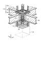
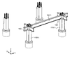
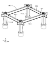
- FIG. 1 A schematic perspective view of the entire structure 100 is shown in FIG. As shown in FIG. 1, the structure 100 includes a plurality of columns 110 extending in the vertical direction (z-direction), a plurality of beams 120 connected to the columns 110 and extending in the horizontal direction, and the beams 120 provided on the beams 120.
- a floor slab 170 is provided as a basic configuration. Only a portion of the floor slab 170 is shown in FIG. 1 for ease of viewing.
- Pillars The number of pillars 110 is not particularly limited as long as it is four or more, and the number and arrangement of the pillars 110 may be appropriately determined according to the size and shape of the structure 100 .
- the pillars 110 are provided on piles (not shown) and connected to foundation beams.
- the shape of the pillar 110 (end face shape in the xy plane) is also arbitrary, and may be appropriately selected from square, circular, elliptical, and the like.
- the length of the pillar 110 is also appropriately designed according to the size of the structure 100 and the height of each story.
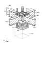
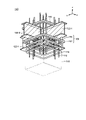
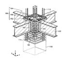
- FIGs. 2 and 3 are perspective views of the joint 140 viewed from above and below, respectively.
- the column 110 includes a steel frame unit such as a plurality of vertically extending column main bars 112 and a plurality of horizontally extending ties 114 surrounding the column main bars. Not embedded in concrete.
- the column main reinforcement 112 penetrates the joint 140 in the vertical direction.
- Each beam 120 is connected to a pair of posts 110 .
- At least one of the beams 120 provided in the structure 100 is a steel beam. That is, at least one of the beams 120 provided in the structure 100 is a steel frame beam having a steel frame 122, both ends of which are joined to the column 110 via joints 140 on the column 110.
- FIG. a part of the beam 120 may be a reinforced concrete beam (RC beam) entirely made of reinforced concrete, or a beam made of a steel frame and reinforced concrete covering both ends of the steel frame (hybrid beam).
- RC beam reinforced concrete beam
- hybrid beam is used for the short span beam 120 (the beam 120 extending in the y direction in FIG.
- a steel beam is used for the long span beam 120 (the beam extending in the x direction in FIG. 1).
- steel beams are lighter than RC beams and hybrid beams, by using steel beams for the beams 120 with long spans, a large indoor space is secured inside the structure 100 and high strength is imparted to the structure 100. be able to.
- a case where the beam 120 is a steel beam will be described below.
- the steel frame 122 that constitutes the beam 120 contains iron, and its end face shape may be H-shaped, I-shaped, T-shaped, L-shaped, or the like.
- the steel frame 122 may be a steel pipe having a circular end surface perpendicular to the longitudinal direction, or a polygonal shape including a square and a rectangle.
- H steel having an H-shaped end surface an end surface perpendicular to the xy plane
- the steel frame 122 is arranged so that the two flanges sandwiching the web are parallel to the horizontal plane.
- the steel frame 122 of each beam 120 is arranged such that at least a portion thereof is inserted into the joint 140 .
- the steel frame 122 may be a truss beam having a structure in which a plurality of combined diagonal members are sandwiched between an upper chord member and a lower chord member.
- the floor slab 170 is reinforced concrete forming the floor surface of each layer and is provided on the beams 120 .
- the floor slab 170 may be provided on each floor, or may not be provided on some floors. Although detailed description is omitted, the floor slab 170 includes a deck plate forming a floor surface, and reinforcing-bar units including reinforcing-bar trusses and slab bars provided on the deck plate. It can be constructed by pouring concrete.
- the joints 140 are units that have the function of connecting the beams 120 and the columns 110 and connecting the beams 120 to each other, and are arranged on the columns 110 .
- the joints 140 connect two, three, four, or more beams 120 to each other according to the structure of the structure 100 and the positions of the columns 110 .
- 2 and 3 show joints 140 for connecting four beams 120 to one column 110.
- each of the four beams 120 may be composed of one steel frame 122, or as shown in FIGS. 1 and two steel frames 122-2 and 122-3 crossing the steel frame 122-1 may be fixed to the steel frame 122-1 by welding and/or bolting.
- the joint 140 includes concrete 142 in which part of the column main reinforcement 112 and part of the steel frame 122 are embedded, as will be described later, and reinforcing members 150 and 160 configured to surround the upper and lower portions of the concrete 142, respectively. contains at least one Joint 140 may have both stiffeners 150 , 160 . The reinforcements 150 , 160 contact the concrete 142 and form part of the outer surface of the joint 140 .
- the joint 140 may further optionally include a surrounding plate 144 provided to cover the side surface of the concrete 142 .
- Surrounding plate 144 is a plate-like member containing metal such as iron, and is provided so as to be in contact with concrete 142 , steel frame 122 , and at least one of reinforcing members 150 and 160 .
- the surrounding plate 144 By providing the surrounding plate 144, the concrete 142 can be restrained and the strength of the joint 140 can be improved.
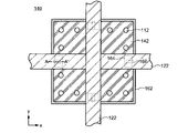
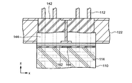
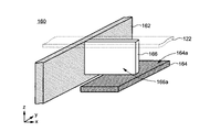
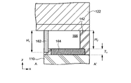
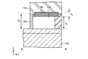
- Reinforcement 160 4A and 4B are a top view and a side view of the joint 140
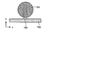
- FIG. 5A is a perspective view of a part of the reinforcing member 160
- FIG. show For ease of understanding, the shroud 144 and stiffener 150 are not shown in FIG. 4A, and only a portion of the shroud 144 is shown in FIG. 4B.
- the concrete 142 is not illustrated in FIG. 5A.
- the stiffener 160 includes a band plate 162 surrounding the concrete 142, at least one rib plate 166 surrounded by the band plate 162 and joined to the band plate 162, and at least one rib plate 166 joined to the rib plate 166. It includes one protective plate 164 .
- the band plate 162 has an annular shape and contains metal such as iron. At least part of the concrete 142 provided at the joint 140 is located within the space formed by the annular shape of the band plate 162 .
- the band plate 162 functions as a shear resisting member at the joint 140 and prevents cracking of the concrete contained in the joint 140 and the column 110 due to the load of the structure 100 . Also, when force is transmitted from the beam 120 of the steel frame 122 to the column 110, the band plate 162 bears the bearing force. As a result, cracks in the column 110 can be suppressed, and bearing pressure failure of the concrete 142 can be prevented.
- the rib plate 166 is a plate-like member containing metal such as iron. Rib plate 166 is positioned such that it is at least partially embedded within concrete 142 (FIG. 5B). The rib plate 166 is surrounded by the band plate 162 and joined to the inner side surface of the band plate 162 by welding or bolting (FIGS. 4A, 5A). Further, the rib plate 166 is arranged such that its main surface 166a is parallel to the vertical direction and extends inwardly of the band plate 162 from the joint position with the band plate 162 (FIG. 5A). A rib plate 166 overlaps one steel frame 122 and is fixed to the steel frame 122 by welding or bolting.
- the rib plate 166 is fixed to the lower flange and lower chord, respectively.
- the band plate 162 is integrated with the steel frame 122 via the rib plate 166 , so the rib plate 166 functions as an out-of-plane shear resistance member of the band plate 162 . That is, the rib plate 166 constrains the band plate 162 that constrains the concrete 142 in the out-of-plane direction, and suppresses the band plate 162 from squeezing, thereby preventing separation between the steel frame 122 and the column 110. can be done.
- the at least one rib plate 166 may include multiple rib plates 166 , for example, as many rib plates 166 as there are beams 120 joined to the column 110 .
- the rib plates 166 are overlapped on the corresponding steel frame 122 so that a straight line connecting a pair of rib plates 166 facing each other intersects a straight line connecting another pair of rib plates 166 facing each other. be joined together.
- the stiffener 160 further comprises at least one protective plate 164 (FIGS. 3, 4A-5B).
- the protective plate 164 is also a plate-shaped member containing metal such as iron, and is joined to the rib plate 166 by welding and/or bolting such that the main surface 164a thereof is parallel to the horizontal direction. Therefore, the major surface 166a of the rib plate 166 and the major surface 164a of the protective plate 164 are perpendicular to each other.
- the protective plate 164 is also surrounded by the band plate 162 and arranged so that the rib plate 166 is positioned between the protective plate 164 and the steel frame 122 . Since the protection plate 164 is positioned at the bottom of the joint 140, it contacts the column 110 and is embedded in the concrete 142 (Figs. 4B and 5B).
- the at least one protection plate 164 may also include multiple protection plates 164 .
- one protection plate 164 may be provided for each of the plurality of rib plates 166 .
- the protection plates 164 are arranged so that a straight line connecting a pair of protection plates 164 facing each other intersects a straight line connecting another pair of protection plates 164 facing each other. can be placed. Therefore, when four beams 120 are joined to the column 110, each protective plate 164 can overlap the corresponding steel frame 122 (Fig. 4A).
- the reinforcing member 160 is configured such that the distance from the lower surface of the steel frame 122 to the lower end of the band plate 162 is smaller than the distance from the lower surface of the steel frame 122 to the lower end of the protective plate 164 in the z direction.
- the reinforcing member 160 is such that the sum of the height (length in the z direction) H2 of the rib plate 166 and the thickness (length in the z direction) T1 of the protection plate 164 is greater than the height H1 of the band plate 162. is also large (FIG. 5B).
- the rib plate height H 2 may be less than or greater than the band plate 162 height H 1 .
- the portion closest to the column 110 becomes the protection plate 164 instead of the band plate 162 or the rib plate 166 .
- the height H 1 of the band plate, the height H 2 of the rib plate 166, and the thickness T 1 of the protective plate 164 satisfy the above-described relationship, so that when the joint 140 is provided on the pillar 110, Since the main surface 164a of the protective plate 164 parallel to the horizontal direction is the portion where the pillar 110 and the joint 140 abut against each other, the impact at the time of contact is dispersed, and as a result, the pillar 110 is effectively prevented from cracking. be able to. Therefore, replacement or repair of the pillar 110 becomes unnecessary, which contributes to the improvement of the quality of the structure 100 and the reduction of the construction cost.
- the protection plate 164 may be fixed to the band plate 162 by welding, bolting, or the like, but may be separated from the band plate 162 as shown in FIGS. 5A and 5B. In the latter case, stiffeners 160 may be configured such that band plates 162 and protective plates 164 do not overlap each other in the z-direction, as shown in FIG. 4A.
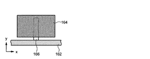
- the shape of the protective plate 164 that is, the shape of the main surface 164a in the xy plane.
- the size and shape of the protective plate 164 are such that the tip of the rib plate 166, that is, the end of the rib plate 166 opposite to the joint with the band plate 162 is vertically covered by the protective plate 164. selected.
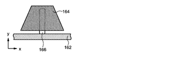
- the shape of the protective plate 164 may be rectangular, or, although not shown, square, triangular, or polygonal with five or more corners. Alternatively, it may be trapezoidal as shown in FIGS. 6B and 6C, or elliptical or circular as shown in FIGS. 6D and 6E.
- the protective plate 164 may have a shape whose contour in the xy plane is composed of straight lines and curved lines.
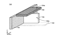
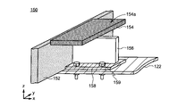
- Reinforcing material 150 7A and 7B are a top view and a side view of the joint 140
- FIG. 8A is a perspective view of a part of the reinforcing member 160
- stiffener 160 is also shown along with stiffener 150 .
- the stiffener 150 includes a band plate 152 configured to surround the concrete 142 , at least one rib plate 156 surrounded by the band plate 152 and joined to the band plate 152 , the rib plate 156 includes at least one protective plate 154 that is bonded to the .
- the band plate 152 Similar to the band plate 162, the band plate 152 also has an annular shape and contains metal such as iron.
- the band plate 152 is arranged on the steel frame 122 so as to cross the steel frame 122 . At least a portion of concrete 142 is located within the space formed by the annular shape of band plate 152 (FIG. 8B). Band plate 152 may have the same shape as band plate 162 .
- the band plate 152 also acts as a shear resistant member for the joint 140 and prevents the joint 140 from cracking due to the loads of the structure 100 . Also, when force is transmitted from the beam 120 of the steel frame 122 to the column 110, the band plate 152 bears the bearing force. As a result, cracks in the column 110 can be suppressed, and bearing pressure failure of the concrete 142 can be prevented.
- the rib plate 156 is also a plate-like member containing metal such as iron. At least a portion of rib plate 156 is embedded in concrete 142 (FIG. 8B). The rib plate 156 is surrounded by the band plate 152 and joined to the inner side surface of the band plate 152 by welding and/or bolting. Further, the rib plate 156 is arranged such that its main surface 156a is parallel to the vertical direction and extends inwardly of the band plate 152 from the joint position with the band plate 152 . A rib plate 156 overlaps one steel frame 122 and is secured to the steel frame 122 by welding and/or bolting. If the steel frame 122 is H steel, the rib plate 156 is fixed to the upper flange.
- the band plate 152 is integrated with the steel frame 122 via the rib plate 156 , so the rib plate 156 functions as an out-of-plane shear resistance member of the band plate 152 .
- the rib plate 166 constrains the band plate 152 that constrains the concrete 142 in the out-of-plane direction, thereby suppressing the band plate 152 from becoming stiff, thereby preventing the gap between the steel frame 122 and the column 110 provided thereon. Separation can be prevented.
- the at least one rib plate 156 may include multiple rib plates 156 , for example, as many rib plates 156 as there are beams 120 joined to the column 110 .
- the rib plates 156 are overlapped on the corresponding steel frame 122 so that a straight line connecting a pair of rib plates 156 facing each other intersects a straight line connecting another pair of rib plates 156 facing each other. be joined together.
- stiffener 150 also comprises at least one protective plate 154 (FIGS. 3, 7A-8B).
- the protective plate 154 is also a plate-shaped member containing metal such as iron, and is joined to the rib plate 156 by welding and/or bolting so that its main surface 154a is parallel to the horizontal direction (FIG. 8A). Therefore, the major surface 156a of the rib plate 156 and the major surface 154a of the protective plate 154 are perpendicular to each other.
- the protective plate 154 is also surrounded by the band plate 152 and arranged so that the rib plate 156 is positioned between the protective plate 154 and the steel frame 122 .
- a protection plate 154 is positioned on top of the joint 140 . Therefore, as described in the second embodiment, it is embedded in grout such as concrete or mortar used when fixing the column 110 on the joint 140 . Note that the protection plate 154 may come into contact with the concrete 142 within the joint 140 .
- the at least one protection plate 154 may also include multiple protection plates 154 .
- one protection plate 154 may be provided for each of the plurality of rib plates 156 .
- the protection plates 154 are arranged so that a straight line connecting a pair of protection plates 154 facing each other intersects a straight line connecting another pair of protection plates 154 facing each other. can be placed. Therefore, when four beams 120 are joined to the column 110, each protective plate 154 can overlap the corresponding steel frame 122 (Fig. 7A).
- the reinforcing member 150 is configured such that the distance from the upper surface of the steel frame 122 to the upper end of the band plate 152 is smaller than the distance from the upper surface of the steel frame 122 to the upper end of the protective plate 154 in the z direction.
- the reinforcing member 150 is such that the sum of the height (length in the z direction) H4 of the rib plate 156 and the thickness ( length in the z direction) T2 of the protection plate 154 is greater than the height H3 of the band plate 152. is also large (FIG. 8B).
- the portion closest to the upper floor pillar 110 is not the band plate 152 or the rib plate 156 but the pillar 110 of the upper floor. It becomes the protective plate 154 .
- the pillars 110 of the upper story come into contact with each other. Since the portion becomes the main surface 154a of the protection plate 154 parallel to the horizontal direction, it is possible to effectively prevent the joint 140 and the pillar 110 of the upper floor from cracking. As a result, there is no need to replace or repair the pillars 110 and the joints 140 of the upper floors, which contributes to improving the quality of the structure 100 and reducing construction costs.
- the height H 3 of the band plate 152 or the sum of the height H 4 of the rib plate 156 and the thickness T 2 of the protective plate 164 must be smaller than the thickness (length in the z direction) of the floor slab 170. is preferred. Thereby, the rib plate 156 and the protective plate 164 can be embedded in the floor slab 170, and the entire floor can be made flat.
- the protection plate 154 may be fixed to the band plate 152 by welding and/or bolting, but may be separated from the band plate 152 as shown in FIGS. 8A and 8B.
- the stiffener 150 may be configured so that the band plate 152 and the protective plate 154 do not overlap in the z-direction, as shown in FIG. 7A.
- the shape of the protective plate 154 that is, the shape of the main surface 154a in the xy plane is not restricted, and can take various shapes like the protective plate 164. Since the explanation about this point is the same as that of the protective plate 164, it is omitted.
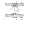
- FIG. 23 is a schematic side view of the band plate 152 as seen from the inside, the reinforcing member 150 further strengthens the steel frame.
- a base plate 158 may be included as a feature for securing with 122 .
- a base plate 158 is also positioned within the space formed by the annular shape of the band plate 152 and is fixed to the sides of the band plate 152 and the rib plate 156 by welding and/or bolting.
- a base plate 158 is positioned below the rib plate 156 so that the normal to its major surface is vertical.
- the base plate 158 is provided with bolt holes through which the threaded portions of the bolts 159 pass, and the base plate 158 can be fixed to the steel frame 122 using the bolts 159 .
- the stiffener 160 may also have a base plate 168, as shown in FIG. Like the base plate 158 , it is positioned within the space defined by the annular shape of the band plate 162 and is welded and/or bolted to the sides of the band plate 162 and the rib plate 166 .
- the base plate 168 is placed on the rib plate 166 so that the normal to its main surface is vertical.
- the base plate 168 can be provided with bolt holes through which the threaded portions of the bolts 169 pass, and the base plate 168 can be fixed to the steel frame 122 using the bolts 169 .
- the direction of the bolt 169 may be the same as the direction of the bolt 159, or may be opposite.
- the surrounding plate 144 is provided so as to cover the sides of the concrete 142 exposed from the reinforcing members 150 and 160 and the steel frame 122, and is continuous between adjacent surfaces parallel to the vertical direction of the concrete 142. (See Figure 2).
- the structure of the joint 140 is not limited to this, and instead of the surrounding plate 144, the joint 140 may include a stiffener 145 that selectively covers the concrete 142 overlapping the steel frame 122 and exposes other portions.
- the stiffener 145 can be provided to cover the concrete 142 between the upper and lower flanges and expose other portions (FIG. 9A).
- a plurality of lateral reinforcements 146 surrounding the column main reinforcement 112 may be provided within the joint 140 .
- the lateral reinforcing bars 146 are annular reinforcing bars penetrating the steel frame.
- the horizontal reinforcing bar 146 may be composed of a single reinforcing bar, or may be formed by combining a plurality of L-shaped reinforcing bars and joining them together by welding or the like, as shown in FIG. 9B.
- Lateral reinforcing bars 146 are also embedded in the concrete 142 at the joints 140 .
- a plurality of inserts 148 may be used together with or in place of the lateral reinforcing bars 146 .
- the insert bars 148 are U-shaped reinforcing bars that surround a plurality of column main bars 112 arranged between the two steel frames 122 that are perpendicular to each other, and each insert bar 148 is also arranged between the two steel frames 122 that are perpendicular to each other. be done.
- the construction of the structure 100 can be performed by fixing the joints 140 to which the beams 120 are connected on the pillars 110, for example.
- the joint 140 is lifted by a lifting machine such as a crane and installed at a predetermined location.
- the joint 140 may be damaged. When such damage occurs, not only does the strength of the column 110 and joint 140 decrease, but the damage needs to be repaired. This causes a delay in the construction period and an increase in the construction cost.
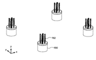
- pillars 110-1 are installed on piles 180 driven into the ground (Figs. 11A and 11B).
- a plurality of pile head anchoring reinforcements 182 are provided at the pile heads of the piles 180, respectively, and a pillar 110-1 is provided on the pile 180 so that these pile head anchoring muscles 182 can be inserted.
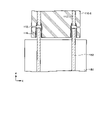
- each column 110-1 has an opening formed under the column main reinforcement 112 so as to overlap the column main reinforcement 112, and a sleeve joint 116 is provided in the opening. be done.
- grout such as ready-mixed concrete or mortar is injected into the grout injection port 118 reaching the sleeve joint 116 from the side of the column 110-1 and hardened. Pile 180 and column 110-1 are fixed.
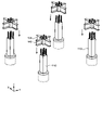
- a beam unit 190-1 that is, a steel frame 122-1 with joints 140 joined to both ends is prepared in advance, and lifted using a lifting machine such as a crane. Move so that it is located above -1 (Fig. 13).
- Each joint 140 is joined with a steel frame 122-1 that connects the pair of joints 140, and one or more beam brackets 124 configured to be connected to a steel frame 122-2 (described later).
- Each beam bracket 124 is provided so that its extending direction intersects with the extending direction of the other beam bracket 124 or the steel frame 122-1.
- the beam unit 190 is gradually lowered, and the joint 140 is installed on the column 110-1 so that the column main reinforcement 112 penetrates the joint 140 (FIG. 14).
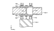
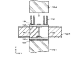
- Figs. 15A and 15B are schematic side views centered on the joint 140 at this time. In these figures, only a portion of the surrounding plate 144 is shown for ease of viewing.
- joint 140 is provided with reinforcing member 160 including band plate 162 and protective plate 164 and reinforcing member 150 including band plate 152 and protective plate 154 .
- the stiffeners 160, 150 may have the base plates 168, 158 described above, in which case bolts 169, 159 secure the stiffeners 160, 150 to the steel frame 122-1 or the beam bracket 124. As indicated by the arrow in FIG.
- the beam unit 190 is gradually lowered so that the column main reinforcement 112 penetrates the joint 140, and the joint 140 is installed on the column 110-1 (FIG. 15B).
- the stiffener 150 may be installed after the joint 140 is installed on the column 110-1. That is, the beam unit 190 provided with the reinforcing member 160 without the reinforcing member 150 is installed on the column 110-1. The stiffener 150 may then be installed on the beam unit 190 .
- the reinforcing member 150 has a base plate 158 , after the reinforcing member 150 is installed on the beam unit 190 , the reinforcing member 150 is fixed to the steel frame 122 - 1 and the beam bracket 124 with bolts 159 .
- the beam unit 190 When installing the beam unit 190, it may not always be possible to lower the beam unit 190 onto the column 110-1 at a sufficiently low speed depending on the operation of the lifting machine and the external environment during construction. When the beam unit 190 is lowered onto the column 110-1 at a relatively high speed, a strong impact is applied to the column 110-1. 1 is damaged and a defect occurs.
- the portion where the joint 140 contacts the column 110-1 becomes a protective plate 164 provided on the reinforcing member 160.
- the band plate 162 or rib plate 166 which has a small area in the xy plane, is prevented from coming into contact with the pillar 110-1. Distributed over major surface 164a.
- the protective plate 164 may be deformed by impact, the band plate 162 and the column 110-1 are prevented from being damaged.
- the beam unit 190-1 is fixed onto the column 110-1.
- the protective plate 164 is embedded in the concrete 142 (Fig. 15B).
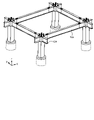
- beam units 190-2 are installed and fixed on the other pair of pillars 110-2 (Fig. 16).
- the steel frame 122-2 can be fixed to the beam brackets 124 of the beam units 190-1 and 190-2. Fixation of the steel frame 122-2 may be performed by welding and/or bolting.
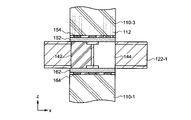
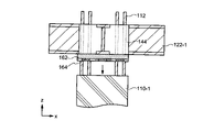
- a pillar 110-3 is installed on the joint 140 (Fig. 17). Installation of the pillar 110-3 may be performed in the same manner as the installation of the pillar 110-1 on the pile 180.
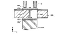
- Figs. 18A and 18B show schematic side views centered on the joint 140 at this time. In these figures, only a portion of the surrounding plate 144 is shown for ease of viewing.
- the column 110-3 is gradually lowered while inserting the column main reinforcement 112 of the column 110-1 into the column 110-3, and the column 110-3 is installed on the joint 140. At this time, if the column 110-3 is lowered to the joint 140 at a relatively high speed, a strong impact is applied to the joint 140, causing damage to the concrete 142 of the joint 140, the band plate 152, and the column 110-3. sell.
- the joint 140 of the structure 100 can be provided with a reinforcement 150 configured to surround the concrete upper portion of the joint 140 .
- the portion where the joint 140 abuts against the column 110-3 becomes a protective plate 154 provided on the reinforcing member 150.
- the band plate 152 or rib plate 156 which has a small area in the xy plane, is prevented from coming into contact with the column 110-3, and the impact received from the column 110-3 is transferred to the main surface 154a of the protective plate 154 perpendicular to the vertical direction. distributed to As a result, the band plate 152, the column 110-3, and the concrete 142 are prevented from being damaged, although the protection plate 154 may be deformed by impact.
- the prefabricated columns 110 are installed on the piles 180 and the joints 140, but the columns 110 may be fabricated by a so-called casting-in-place method. That is, the column 110 may be manufactured by providing a formwork on the pile 180 or the joint 140, pouring the ready-mixed concrete into the formwork, and hardening it.
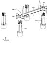
- the joint 140 to which the beam bracket 124 is joined and the column unit 192 in which the column 110 is previously fixed by concrete 142 may be installed on the pile 180 (Fig. 19).
- the joint 140 to which the beam bracket 124 is joined is installed on the pillar 110, and then the joint 140 is placed on the pillar 110 by pouring concrete 142 into the joint 140.
- the steel frame 122 is fixed to the beam brackets 124 of the pair of columns 110 (FIG. 21). After that, the structure 100 can be constructed by repeating the same steps.
- the joints 140 provided on the columns 110 and joining the columns 110 and the beams 120 and the beams 120 to each other are cast into the joints 140.
- At least one of the stiffeners 150, 160 is provided surrounding the top and bottom of the concrete 142 to be cemented, respectively. Since protective plates 154 and 164 having main surfaces perpendicular to the vertical direction are provided on both reinforcing members 150 and 160, it is possible to prevent defects caused by collisions between columns 110 and joints 140 during construction of structure 100. can do. As a result, delays in the construction period due to defective repairs can be prevented, and the structure 100 can be constructed at low cost.
Landscapes
- Engineering & Computer Science (AREA)
- Architecture (AREA)
- Physics & Mathematics (AREA)
- Electromagnetism (AREA)
- Civil Engineering (AREA)
- Structural Engineering (AREA)
- Joining Of Building Structures In Genera (AREA)
Priority Applications (2)
| Application Number | Priority Date | Filing Date | Title |
|---|---|---|---|
| JP2022576999A JP7529813B2 (ja) | 2021-01-21 | 2021-11-19 | 構造体とその施工方法 |
| MX2023008558A MX2023008558A (es) | 2021-01-21 | 2021-11-19 | Estructura y metodo de construccion de la misma. |
Applications Claiming Priority (2)
| Application Number | Priority Date | Filing Date | Title |
|---|---|---|---|
| JP2021008170 | 2021-01-21 | ||
| JP2021-008170 | 2021-01-21 |
Publications (1)
| Publication Number | Publication Date |
|---|---|
| WO2022158103A1 true WO2022158103A1 (ja) | 2022-07-28 |
Family
ID=82548698
Family Applications (1)
| Application Number | Title | Priority Date | Filing Date |
|---|---|---|---|
| PCT/JP2021/042645 Ceased WO2022158103A1 (ja) | 2021-01-21 | 2021-11-19 | 構造体とその施工方法 |
Country Status (4)
| Country | Link |
|---|---|
| JP (1) | JP7529813B2 (enExample) |
| MX (1) | MX2023008558A (enExample) |
| TW (1) | TWI870643B (enExample) |
| WO (1) | WO2022158103A1 (enExample) |
Citations (6)
| Publication number | Priority date | Publication date | Assignee | Title |
|---|---|---|---|---|
| JPH0480444A (ja) * | 1990-07-20 | 1992-03-13 | Ohbayashi Corp | 鉄筋コンクリート柱と鉄骨梁との接続ユニット |
| KR20010028920A (ko) * | 1999-09-28 | 2001-04-06 | 김헌출 | 철근콘크리트 기둥과 철골 보의 접합부 |
| JP2005061081A (ja) * | 2003-08-13 | 2005-03-10 | Shimizu Corp | プレキャストスラブの接合構造、及びプレキャストスラブの接合方法 |
| JP5518346B2 (ja) * | 2009-02-25 | 2014-06-11 | 株式会社フジタ | 柱梁接合部の構造 |
| CN108222280A (zh) * | 2017-12-29 | 2018-06-29 | 中国十七冶集团有限公司 | 一种装配式混凝土构件干式连接装置 |
| JP2019143422A (ja) * | 2018-02-23 | 2019-08-29 | 株式会社フジタ | 柱梁接合部の補強構造 |
-
2021
- 2021-11-19 MX MX2023008558A patent/MX2023008558A/es unknown
- 2021-11-19 WO PCT/JP2021/042645 patent/WO2022158103A1/ja not_active Ceased
- 2021-11-19 JP JP2022576999A patent/JP7529813B2/ja active Active
-
2022
- 2022-01-19 TW TW111102219A patent/TWI870643B/zh active
Patent Citations (6)
| Publication number | Priority date | Publication date | Assignee | Title |
|---|---|---|---|---|
| JPH0480444A (ja) * | 1990-07-20 | 1992-03-13 | Ohbayashi Corp | 鉄筋コンクリート柱と鉄骨梁との接続ユニット |
| KR20010028920A (ko) * | 1999-09-28 | 2001-04-06 | 김헌출 | 철근콘크리트 기둥과 철골 보의 접합부 |
| JP2005061081A (ja) * | 2003-08-13 | 2005-03-10 | Shimizu Corp | プレキャストスラブの接合構造、及びプレキャストスラブの接合方法 |
| JP5518346B2 (ja) * | 2009-02-25 | 2014-06-11 | 株式会社フジタ | 柱梁接合部の構造 |
| CN108222280A (zh) * | 2017-12-29 | 2018-06-29 | 中国十七冶集团有限公司 | 一种装配式混凝土构件干式连接装置 |
| JP2019143422A (ja) * | 2018-02-23 | 2019-08-29 | 株式会社フジタ | 柱梁接合部の補強構造 |
Also Published As
| Publication number | Publication date |
|---|---|
| TW202233949A (zh) | 2022-09-01 |
| JPWO2022158103A1 (enExample) | 2022-07-28 |
| JP7529813B2 (ja) | 2024-08-06 |
| TWI870643B (zh) | 2025-01-21 |
| MX2023008558A (es) | 2023-12-01 |
Similar Documents
| Publication | Publication Date | Title |
|---|---|---|
| KR100971736B1 (ko) | 상하 각각 이중 앵커리지 기능을 갖는 전단보강재 | |
| JP4823790B2 (ja) | 柱ユニットおよび柱ユニットを用いた建物の施工方法 | |
| JP2007016594A (ja) | 合成パネル構造およびパネル橋梁構造ならびに連続合成桁橋の施工方法 | |
| JP2003253621A (ja) | 既設単純桁橋梁を連続化した連続桁構造 | |
| JP3999114B2 (ja) | 橋梁の主桁の切欠きコーナー部の補強方法及び補強構造 | |
| KR100856723B1 (ko) | 캔틸레버형 지지거더를 이용한 철골조 역타설 시스템 및방법 | |
| KR102274358B1 (ko) | 교량 구조물의 캔틸레버용 프리캐스트 바닥판 | |
| KR20190084712A (ko) | 기초보강부 일체형 선조립 기둥 조립체 | |
| KR100676627B1 (ko) | 슬래브―기둥 접합부의 전단보강체 및 이를 이용한전단보강구조 | |
| JP7694135B2 (ja) | 接続構造及び接続方法 | |
| JP3106881B2 (ja) | 鉄筋コンクリート柱と鉄骨梁との混合構造 | |
| JP4508293B2 (ja) | 連続i桁橋の中間支点近傍の構造 | |
| JP7529813B2 (ja) | 構造体とその施工方法 | |
| CN118756812A (zh) | 一种装配整体式梁板一体化框架结构及其安装方法 | |
| KR102695935B1 (ko) | 데크-하프빔모듈 일체형 선조립 모듈 | |
| JP5029271B2 (ja) | 連続i桁橋およびその中間支点近傍のi桁の構造 | |
| JP2003293323A (ja) | 連続桁橋梁の補強構造 | |
| JP2000008325A (ja) | 床版合成桁構造 | |
| JP4492422B2 (ja) | 連続i桁橋の中間支点近傍の構造 | |
| JP2003049410A (ja) | 鋼製ラーメン橋脚の隅角部の補強構造 | |
| JP7788833B2 (ja) | 機械類設置用の新設基礎 | |
| JP7746641B2 (ja) | PCa接合部材 | |
| JP7502710B2 (ja) | 接合構造および接合構造の構築方法 | |
| JP3950748B2 (ja) | 橋桁 | |
| KR102416758B1 (ko) | 교량용 캔틸레버 구조체 및 교량용 캔틸레버 구조체 시공 방법 |
Legal Events
| Date | Code | Title | Description |
|---|---|---|---|
| 121 | Ep: the epo has been informed by wipo that ep was designated in this application |
Ref document number: 21921206 Country of ref document: EP Kind code of ref document: A1 |
|
| ENP | Entry into the national phase |
Ref document number: 2022576999 Country of ref document: JP Kind code of ref document: A |
|
| WWE | Wipo information: entry into national phase |
Ref document number: MX/A/2023/008558 Country of ref document: MX |
|
| NENP | Non-entry into the national phase |
Ref country code: DE |
|
| 122 | Ep: pct application non-entry in european phase |
Ref document number: 21921206 Country of ref document: EP Kind code of ref document: A1 |
|
| WWG | Wipo information: grant in national office |
Ref document number: MX/A/2023/008558 Country of ref document: MX |