WO2022157974A1 - 処置具 - Google Patents
処置具 Download PDFInfo
- Publication number
- WO2022157974A1 WO2022157974A1 PCT/JP2021/002444 JP2021002444W WO2022157974A1 WO 2022157974 A1 WO2022157974 A1 WO 2022157974A1 JP 2021002444 W JP2021002444 W JP 2021002444W WO 2022157974 A1 WO2022157974 A1 WO 2022157974A1
- Authority
- WO
- WIPO (PCT)
- Prior art keywords
- forceps
- rod
- forceps piece
- piece
- treatment instrument
- Prior art date
- Legal status (The legal status is an assumption and is not a legal conclusion. Google has not performed a legal analysis and makes no representation as to the accuracy of the status listed.)
- Ceased
Links
Images







Classifications
-
- A—HUMAN NECESSITIES
- A61—MEDICAL OR VETERINARY SCIENCE; HYGIENE
- A61B—DIAGNOSIS; SURGERY; IDENTIFICATION
- A61B17/00—Surgical instruments, devices or methods
- A61B17/28—Surgical forceps
-
- A—HUMAN NECESSITIES
- A61—MEDICAL OR VETERINARY SCIENCE; HYGIENE
- A61B—DIAGNOSIS; SURGERY; IDENTIFICATION
- A61B18/00—Surgical instruments, devices or methods for transferring non-mechanical forms of energy to or from the body
- A61B18/04—Surgical instruments, devices or methods for transferring non-mechanical forms of energy to or from the body by heating
- A61B18/12—Surgical instruments, devices or methods for transferring non-mechanical forms of energy to or from the body by heating by passing a current through the tissue to be heated, e.g. high-frequency current
Definitions
- the present invention relates to treatment tools.
- endoscopic treatment tools for incision and dissection such as high-frequency knives
- endoscopic treatment tools for incision and dissection such as high-frequency knives
- Patent Document 1 describes a high-frequency knife that can perform tissue incision/stripping and hemostasis.
- the high-frequency knife described in Patent Literature 1 can perform hemostatic treatment with hemostatic forceps.
- the present invention provides a treatment instrument capable of performing an incision/ablation procedure and a hemostatic treatment, which facilitates a switching operation between the treatment instrument for performing the incision/ablation procedure and the hemostatic forceps for performing the hemostatic procedure.
- An object is to provide a treatment tool.
- a treatment instrument includes a sheath, forceps provided at the distal end of the sheath so as to be openable and closable, and a rod provided at the distal end of the sheath so as to be protruding and retractable and to which a high-frequency current is applied.
- an operating portion provided at the proximal end of the sheath for moving the rod forward and backward;
- the radial length of the abutting portion is longer than the radial length of the rod body, and the receiving portion is abutted against the abutting portion of the retracted rod. , displaces said forceps in said radial direction.
- the treatment instrument of the present invention it is possible to perform incision/ablation treatment and hemostatic treatment, and switching operation between the treatment instrument for incision/ablation treatment and the hemostatic forceps for hemostatic treatment is easy.
- FIG. 1 is an overall view of an endoscopic treatment system according to a first embodiment;
- FIG. It is an overall view showing a treatment tool of the endoscope treatment system. It is a side view of the front-end
- FIG. 11 is a side view of the electrode section and forceps passing through the second rod passage area; It is a side view of the front-end
- FIG. 12 is a cross-sectional view of the holding tube and the like taken along line XX of FIG. 11; It is a side view of the front-end
- FIG. 17 is a cross-sectional view of the forceps or the like along line YY in FIG. 16; It is sectional drawing of the front-end
- FIG. 1 is an overall view of an endoscope treatment system 300 according to this embodiment.
- the endoscope treatment system 300 includes an endoscope 200 and a treatment instrument 100, as shown in FIG.
- the treatment instrument 100 is used by being inserted into the endoscope 200 .
- the endoscope 200 is a known flexible endoscope, and includes an insertion section 202 that is inserted into the body from its distal end, and an operation section 207 attached to the proximal end of the insertion section 202 .
- the insertion section 202 has an imaging section 203 , a bending section 204 and a flexible section 205 .
- the imaging section 203 , the bending section 204 and the flexible section 205 are arranged in this order from the distal end of the insertion section 202 .
- a channel 206 for inserting the treatment instrument 100 is provided inside the insertion portion 202 .
- a distal end opening 206 a of a channel 206 is provided at the distal end of the insertion portion 202 .
- the imaging unit 203 is equipped with an imaging device such as a CCD or CMOS, and is capable of imaging the site to be treated.
- the imaging unit 203 can image the forceps 3 of the treatment instrument 100 in a state in which the treatment instrument 100 protrudes from the tip opening 206 a of the channel 206 .
- the bending portion 204 bends according to the operation of the operating portion 207 by the operator.
- the flexible portion 205 is a flexible tubular portion.
- the operation section 207 is connected to the flexible section 205 .
- the operation portion 207 has a grip 208 , an input portion 209 , a base end opening 206 b of the channel 206 and a universal cord 210 .
- a grip 208 is a part that is gripped by an operator.
- the input unit 209 receives an operation input for bending the bending unit 204 .
- the universal code 210 outputs the image captured by the imaging unit 203 to the outside.
- the universal code 210 is connected to a display device such as a liquid crystal display via an image processing device including a processor.
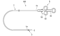
- FIG. 2 is an overall view showing the treatment instrument 100.
- the treatment instrument 100 is a treatment instrument capable of performing an incision/stripping treatment and a hemostatic treatment.
- the treatment instrument 100 includes a sheath 1 , a rod 2 , forceps (jaws) 3 , an operation wire 4 (shown in FIG. 4), and an operation portion 5 .
- the side to be inserted into the patient's body is called the "distal end side (A1)"
- the operation section 5 side is called the "base end side (A2)”.
- the sheath 1 is an elongated member having flexibility and insulating properties and extending from the distal end 1a to the proximal end 1b. Sheath 1 has an outer diameter that allows it to be inserted into channel 206 of endoscope 200 . As shown in FIG. 1 , when the sheath 1 is inserted into the channel 206 , the tip 1 a of the sheath 1 can protrude from the tip opening 206 a of the channel 206 . Also, the edge of the tip of the sheath 1 may be rounded.
- FIG. 3 is a side view of the distal end portion of the treatment instrument 100.
- the rod 2 is a substantially round bar-shaped member made of a metal material such as stainless steel, and is provided so as to protrude from the distal end 1a of the sheath 1 .
- the rod 2 has a rod body 20, an electrode portion 21, and a stopper 22 (illustrated in FIG. 4).
- FIG. 4 is a cross-sectional view of the distal end portion of the treatment instrument 100.
- Rod 2 is movable along longitudinal direction A and passes through forceps 3 .
- a central axis O2 in the longitudinal direction A of the rod 2 substantially coincides with a central axis O1 in the longitudinal direction A of the sheath 1 .
- the rod body 20 is a round bar-shaped member made of a metal material such as stainless steel.
- An operating wire 4 is attached to the proximal end of the rod body 20 .
- the operating wire 4 is connected to the rod body 20 by a stopper 22 .
- the rod main body 20 supplies the electrode section 21 and the forceps 3 with high-frequency current supplied from the operation wire 4 connected to the operation section 5 .
- a portion of the rod body 20 exposed from the distal end of the forceps 3 and the electrode portion 21 function as a high-frequency electrode for applying a high-frequency current to living tissue, and are mainly used for incision and ablation procedures. However, depending on the situation, the portion where the rod body 20 is exposed from the tip of the forceps 3 and the electrode portion 21 may be used for hemostatic treatment.
- FIG. 5 is a front view of the distal end portion of the treatment instrument 100 with the forceps 3 closed.
- the electrode portion 21 is a disk-shaped conductive member provided at the tip of the rod body 20 .
- the outer circumference of the electrode portion 21 is formed concentrically with the outer circumference of the rod body 20 when viewed from the front in a direction horizontal to the longitudinal direction A.
- the length L1 of the radial direction R perpendicular to the longitudinal direction A of the electrode portion 21 is longer than the length L2 of the radial direction R of the rod body 20 .
- the stopper 22 is provided on the outer periphery of the rod body 20 and the operation wire 4 and connects the rod body 20 and the operation wire 4 . Also, the stopper 22 regulates the length of the rod body 20 exposed from the tip of the forceps 3 . As a result, the protrusion amount of the electrode portion 21 is also restricted. As shown in FIG. 4, the stopper 22 regulates the projection amount of the electrode portion 21 with respect to the sheath 1 by engaging with the engaging portion 1c provided at the distal end 1a of the sheath 1. As shown in FIG.
- the forceps (jaws) 3 are conductive members made of a metal material such as stainless steel.
- the forceps 3 have the function of a high-frequency electrode that applies a high-frequency current to living tissue, and mainly perform hemostasis.
- the forceps 3 has a first forceps piece 31, a second forceps piece 32, and a connecting portion 34, as shown in FIG.
- the first forceps piece 31 and the second forceps piece 32 are connected at a connecting portion 34 on the base end side A2, and are provided so as to be openable and closable toward the distal end side A1.
- the connecting portion 34 is biased so that the first forceps piece 31 and the second forceps piece 32 come into contact and close.
- the connecting portion 34 is housed inside the distal end 1 a of the sheath 1 .
- the first forceps piece 31 and the second forceps piece 32 are arranged symmetrically with respect to the central axis O3 in the longitudinal direction A of the forceps 3 .
- the central axis O3 in the longitudinal direction A of the forceps 3 substantially coincides with the central axis O1 in the longitudinal direction A of the sheath 1.
- FIG. 4 shows that the central axis O3 in the longitudinal direction A of the forceps 3 substantially coincides with the central axis O1 in the longitudinal direction A of the sheath 1.
- the rod 2 passes through the connecting portion 34 where the first forceps piece 31 and the second forceps piece 32 are connected, and passes through the region sandwiched between the first forceps piece 31 and the second forceps piece 32 .
- the area sandwiched between the first forceps piece 31 and the second forceps piece 32 and through which the rod 2 passes is also referred to as "rod passage area E".
- FIG. 6 is a front view of the distal end of the treatment instrument 100 with the forceps 3 opened.
- the first forceps piece 31 includes a first concave bottom portion 311 provided on the distal end side A1, a first arc-shaped edge portion 312 provided at a position facing the second forceps piece 32, and a base of the first concave bottom portion 311. and a first proximal support 315 (shown in FIG. 7) provided on the end side A2.
- the first concave bottom portion 311 is formed in a cup shape and opens toward the second forceps piece 32 side in the opening/closing direction B of the forceps 3 .
- the first arcuate edge portion 312 is the opening edge of the first concave bottom portion 311 and is formed in an arc shape.
- the first arcuate edge 312 has a first tip recess 313 and a first serration 314 .
- the first tip recess 313 is a recess provided on the tip side.
- the first sawtooth portion 314 is a sawtooth-shaped unevenness provided on both sides in the width direction C perpendicular to the longitudinal direction A and the opening/closing direction B. As shown in FIG.
- the first proximal support portion (receiving portion) 315 is formed extending in the longitudinal direction A and supports the first concave bottom portion 311 on the distal end side A1.
- the first base end support portion 315 is arranged closer to the central axis O3 than the first concave bottom portion 311 is.
- the second forceps piece 32 includes a second concave bottom portion 321 provided on the distal end side A1, a second arcuate edge portion 322 provided at a position facing the first forceps piece 31, and a base of the second concave bottom portion 321. and a second base end support portion 325 provided on the end side A2.
- the second concave bottom portion 321 is formed in a cup shape and opens toward the first forceps piece 31 side in the opening/closing direction B of the forceps 3 .
- the second arcuate edge portion 322 is the opening edge of the second concave bottom portion 321 and is formed in an arc shape.
- the second arcuate edge portion 322 has a second tip recess 323 and a second serrated portion 324 .
- the second tip recess 323 is a recess provided on the tip side.
- the second sawtooth portion 324 is a sawtooth-shaped unevenness provided on both sides in the width direction C. As shown in FIG.
- the second proximal support portion (receiving portion) 325 is formed extending in the longitudinal direction A and supports the second concave bottom portion 321 on the distal end side A1.
- the second base end support portion 325 is arranged closer to the central axis O3 than the second concave bottom portion 321 is.
- the through-hole 33 is formed in a circular shape centered on the central axis O3 when viewed from the front in a direction horizontal to the longitudinal direction A.
- the radial length L3 of the through-hole 33 in the radial direction R is longer than the radial length L1 of the electrode portion 21 in the radial direction R, as shown in FIG. Therefore, the rod main body 20 and the electrode portion 21 can move back and forth along the longitudinal direction A in the through hole 33 .
- the movement of the rod 2 to the side A1 of the prior application is also referred to as "forward”
- the movement to the proximal side A2 is also referred to as "backward”.
- first rod passage area E1 In the closed state where the first forceps piece 31 and the second forceps piece 32 are closed, as shown in FIG.
- the length L4 is longer than the length L1 of the electrode portion 21 in the radial direction R.
- the rod passage area E sandwiched between the first concave bottom portion 311 and the second concave bottom portion 321 is also referred to as "first rod passage area E1".
- the rod body 20 and the electrode portion 21 extend along the longitudinal direction A in the first rod passage area E1. can move forward and backward.
- the rod passage area E sandwiched between the first proximal support portion 315 and the second proximal support portion 325 is also referred to as "second rod passage area E2".
- the rod body 20 can move back and forth along the longitudinal direction A in the second rod passage area E2 in the closed state in which the first forceps piece 31 and the second forceps piece 32 are closed.
- the length L5 is shorter than the length L1
- the electrode portion 21 advances and retreats in the second rod passage area E2 along the longitudinal direction A
- the first base end support portion 315 and the second base end support portion 325 come into contact with at least one part of
- the length L5 in the radial direction R of the second rod passage area E2 is the length between the first proximal end support portion 315 and the second proximal end support when the first forceps piece 31 and the second forceps piece 32 are in the closed state.
- 325 is the shortest length.
- the electrode portion 21 contacts at least one of the first proximal support portion 315 and the second proximal support portion 325 when passing through the second rod passage area E2.
- a high-frequency current is applied to the first forceps piece 31 when the electrode portion 21 contacts the first proximal end support portion 315 in an energized state. Further, when the electrode portion 21 contacts the second base end support portion 325 while the electrode portion 21 is energized, a high frequency current is energized to the second forceps piece 32 .
- the electrode portion 21 is energized and the first forceps piece 31 and the second forceps piece 32 may be energized with a high frequency current.
- the first forceps piece 31 and the second forceps piece 32 have an insulating coating on the outer surface opposite to the rod passage area E side. Specifically, a portion of the first forceps piece 31 other than the first concave bottom portion 311 and the first arcuate edge portion 312 and a portion of the second forceps piece 32 other than the second concave bottom portion 321 and the second arcuate edge portion 322 The part is provided with an insulating coating. With this configuration, it is possible to reduce the possibility of cauterizing an unintended tissue when the forceps 3 are energized.
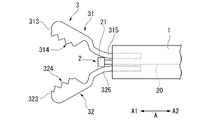
- FIG. 7 is a side view of the electrode section 21 and the forceps 3 passing through the second rod passage area E2.
- the electrode section 21 passes through the second rod passage area E2, it contacts the first proximal support section 315 and the second proximal support section 325, and the first proximal support section 315 and the second proximal support section 325 and are pushed aside in the radial direction R.
- the electrode part 21 functions as a "butting part" for the first proximal support part 315 and the second proximal support part 325 when passing through the second rod passage area E2.
- the first forceps piece 31 and the second forceps piece 32 change from the closed state to the open state.
- the operation wire 4 is a wire made of a metal material such as stainless steel, and is inserted through the inner space 1s of the sheath 1. As shown in FIG. 4 , the distal end of the operating wire 4 is connected to the stopper 22 and the proximal end of the operating wire 4 is connected to the operating portion 5 .
- the operation unit 5 has an operation unit main body 51, a slider 52, and a power supply connector 53, as shown in FIGS.
- the distal end of the operation portion main body 51 is connected to the proximal end 1b of the sheath 1.
- the operation portion main body 51 has an internal space through which the operation wire 4 can be inserted.
- the operating wire 4 passes through the inner space of the sheath 1 and the inner space of the operating portion main body 51 and extends to the slider 52 .
- the slider 52 is attached to the operation portion main body 51 so as to be movable along the longitudinal direction A.
- a base end portion of the operation wire 4 is connected to the slider 52 .
- the operation wire 4 and the rod 2 move forward and backward relative to the sheath 1 by the operator moving the slider 52 forward and backward relative to the operation portion main body 51 .
- a power supply connector 53 is fixed to the slider 52 .
- the power supply connector 53 can be connected to a high-frequency power supply (not shown), and is electrically and physically connected to the proximal end of the operation wire 4 .
- the power supply connector 53 can supply high-frequency current supplied from the high-frequency power supply to the electrode section 21 and the forceps 3 via the operation wire 4 and the rod 2 .
- the operator identifies the lesion by a known method and bulges the lesion. Specifically, the operator inserts the insertion portion 202 of the endoscope 200 into the digestive tract (e.g., esophagus, stomach, duodenum, large intestine), and observes images obtained by the imaging unit 203 of the endoscope to detect lesions. Identify the part. Next, the operator inserts a known submucosal injection needle into the channel 206 of the insertion portion 202, injects a liquid for local injection (local injection liquid) through the submucosal injection needle, and bulges the lesion. After injecting the local injection solution, the submucosal local injection needle is removed from the channel 206 .
- the digestive tract e.g., esophagus, stomach, duodenum, large intestine
- a known submucosal injection needle into the channel 206 of the insertion portion 202, injects a liquid for local injection (local injection liquid) through the
- the operator inserts the treatment instrument 100 into the channel 206 and protrudes the distal end 1a of the sheath 1 from the distal end opening 206a of the insertion section 202 .
- the caregiver advances the slider 52 of the operating portion 5 relative to the operating portion main body 51 to project the rod 2 .
- the operator advances the rod 2 and moves the electrode part 21 in a state where high-frequency current is applied to incise the mucous membrane of the lesion.
- the operator advances the rod 2 to exfoliate the submucosa of the incised lesion while lifting the mucous membrane of the incised lesion and exposing the submucosa while high-frequency current is applied.
- the hemostatic treatment is a treatment for cauterizing an ulcer, an incision, or a bleeding site T that bleeds during the ablation treatment after the lesion is ablated to stop bleeding.
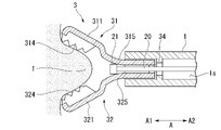
- FIG. 8 is a side view of the distal end portion of the treatment instrument 100 for hemostatic treatment of a bleeding site.
- the operator brings the electrode section 21 into contact with the first proximal support section 315 and the second proximal support section 325 by retracting the electrode section 21 to the second rod passage area E2.
- the electrode portion 21 pushes the first base end support portion 315 and the second base end support portion 325 outward in the radial direction R.
- the first forceps piece 31 and the second forceps piece 32 change from the closed state to the open state.
- the first forceps piece 31 and the second forceps piece 32 are opened widely.
- the operator and the assistant adjust the position of the open forceps 3 by rotating the operating portion 5 clockwise or counterclockwise with respect to the longitudinal direction A, or moving the sheath 1 forward and backward.
- the living tissue at the bleeding site is grasped.
- FIG. 9 is a side view of the distal end portion of a treatment instrument 100 for hemostatic treatment of a bleeding site.
- the operator separates the electrode section 21 from the first proximal support section 315 and the second proximal support section 325 by advancing the electrode section 21 to the first rod passage area E1.
- the first forceps piece 31 and the second forceps piece 32 try to transition from the open state to the closed state.
- the first forceps piece 31 and the second forceps piece 32 grip a living tissue.
- the forceps 3 has a first sawtooth portion 314 and a second sawtooth portion 324 . Therefore, when the operator pinches the living tissue between the first serrated portion 314 and the second serrated portion 324 , the living tissue is less likely to shift with respect to the forceps 3 . As a result, the operator can preferably hold the bleeding site T between the first concave bottom portion 311 and the second concave bottom portion 321 .
- the operator applies high-frequency current to the rod 2 while the first forceps piece 31 and the second forceps piece 32 are in contact with the rod 2 .
- a high-frequency current is applied to the first arc-shaped edge 312 and the second arc-shaped edge 322 with which the living tissue is in contact, and the bleeding site T can be cauterized.
- the electrode section 21 is further advanced to contact the bleeding site T, can be pinpoint cauterized.
- the operator continues the above-described operation (treatment) as necessary, finally excises the lesion, and ends the ESD procedure.
- incision/dissection treatment and hemostatic treatment can be performed, and switching operation between the rod 2 for performing the incision/dissection treatment and the forceps 3 for performing hemostatic treatment is easy.
- the operator can switch between the rod 2 for performing the incision/ablation treatment and the forceps 3 for performing the hemostatic treatment only by moving the rod 2 back and forth.
- the endoscope 200 is a flexible endoscope.
- the treatment instrument 100 may be used together with a rigid endoscope. In that case, the sheath 1 does not have to be flexible.
- the electrode section 21 functions as a "butting section" for the first proximal support section 315 and the second proximal support section 325 when passing through the second rod passage area E2.
- the aspect of the abutting portion that pushes the first base end support portion 315 and the second base end support portion 325 outward in the radial direction R is not limited to this.
- the rod 2 may have an abutting portion separate from the electrode portion 21 .
- FIG. 10 is a side view showing a rod 2A that is a modified example of rod 2.
- the rod 2A has a rod body 20, an electrode portion 21, a stopper 22, and an abutting portion 23.
- the abutting portion 23 is provided on the base end side A2 of the electrode portion 21 .
- the length of the abutting portion 23 in the radial direction R is greater than the length L5.
- the abutting portion 23 is formed in a tapered shape in which the length in the radial direction R increases toward the distal end A1.
- the operator brings the abutting portion 23 back into contact with the first proximal end support portion 315 and the second proximal end support portion 325 by retracting the abutment portion 23 to the second rod passage area E2.
- the abutting portion 23 pushes the first base end support portion 315 and the second base end support portion 325 outward in the radial direction R. Since the abutting portion 23 has the tapered shape as described above, the first forceps piece 31 and the second forceps piece 32 can be smoothly shifted from the closed state to the open state.
- FIG. 11 to 15 A treatment instrument 100B according to a second embodiment of the present invention will be described with reference to FIGS. 11 to 15.
- FIG. 11 to 15 the same reference numerals are given to the same configurations as those already described, and redundant descriptions will be omitted.
- FIG. 11 is a side view of the distal end portion of the treatment instrument 100B.
- the treatment instrument 100B is used as an endoscope treatment system together with the endoscope 200, like the treatment instrument 100 of the first embodiment.
- the treatment instrument 100B is a treatment instrument capable of performing an incision/stripping treatment and a hemostatic treatment.
- the treatment instrument 100B includes a sheath 1B, a rod 2, forceps (jaws) 3B, an operation wire 4 (shown in FIG. 12), an operation portion 5, a holding tube 6, and a spring 7.
- the sheath 1B is the same member as the sheath 1 of the first embodiment except that it has a concave portion 12 on the outer circumference of the tip 1a.
- the recess 12 is formed along the circumferential direction of the sheath 1B.
- FIG. 12 is a cross-sectional view of the distal end portion of the treatment instrument 100B.
- the forceps (jaws) 3B are made of conductive metal and function as high-frequency electrodes for applying high-frequency current to living tissue.
- the forceps 3 has a first forceps piece 31, a second forceps piece 32, and a connecting portion 34B.
- the first forceps piece 31 and the second forceps piece 32 are connected at a connecting portion 34B on the base end side A2, and are provided so as to be openable and closable toward the distal end side A1.
- the connecting portion 34B is biased so that the first forceps piece 31 and the second forceps piece 32 are in an open state.
- the connecting portion 34B is accommodated inside the distal end 1a of the sheath 1B.
- the holding tube (sleeve) 6 is a tubular member slidably provided at the distal end 1a of the sheath 1.
- a convex portion 66 that engages with the concave portion 12 of the sheath 1B is formed along the circumferential direction on the inner peripheral surface of the pressing tube 6 on the proximal end side.
- a central axis O6 in the longitudinal direction A of the holding tube 6 substantially coincides with a central axis O1 in the longitudinal direction A of the sheath 1 .
- the holding tube 6 is a member that accommodates a portion of the forceps 3B and maintains the forceps 3B in a closed state. As shown in FIG. 12, the proximal side A2 of the forceps 3B is housed in the internal space 6s of the holding tube 6. As shown in FIG.
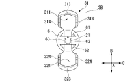
- FIG. 13 is a cross-sectional view of the holding tube 6 and the like taken along line XX in FIG.
- the holding tube 6 has a tip wall 63 that separates an internal space 6s and an external space of the holding tube 6 on the tip side A1.
- the tip wall (receiving portion) 63 has a rod through hole 60 , a first forceps piece through hole 61 , and a second forceps piece through hole 62 .
- the rod through-hole 60 is formed in a circular shape around the central axis O6 when viewed from the front in a direction horizontal to the longitudinal direction A.
- a length L6 in the radial direction R of the rod through hole 60 is longer than a length L2 in the radial direction R of the rod body 20 and shorter than a length L1 in the radial direction R of the electrode portion 21 . Therefore, the rod body 20 can move back and forth along the longitudinal direction A through the rod through-hole 60 .
- the electrode portion 21 cannot pass through the rod through hole 60 .
- the first forceps piece through hole 61 is a through hole through which the first forceps piece 31 is inserted.
- the second forceps piece through-hole 62 is a through-hole through which the second forceps piece 32 is inserted.
- the first forceps piece through-hole 61 and the second forceps piece through-hole 62 are arranged on both sides in the opening/closing direction B with the central axis O6 interposed therebetween.
- the spring 7 is a compression spring housed in the recessed portion 12 of the sheath 1B, and urges the holding tube 6 toward the distal end with a restoring force. As shown in FIG. 12, the spring 7 moves the presser tube 6 to the most distal end side A1, so that the edge of the first forceps piece through-hole 61 moves in the direction to close the first forceps piece 31, and the second forceps piece The edge of the through hole 62 moves the second forceps piece 32 in a closing direction. As a result, the pressing tube 6, which is moved toward the distal end side A1 by the spring 7, closes the forceps 3B against the opening force of the forceps 3B.
- FIG. 14 is a side view of the distal end portion of the treatment instrument 100B with the electrode portion 21 retracted.
- the electrode section 21 contacts the tip wall 63 .
- the electrode portion 21 functions as a “butting portion” against the tip wall 63 when passing through the rod through hole 60 .
- the spring 7 contracts against the restoring force.
- the holding tube 6 moves to the proximal side A2 with respect to the sheath 1B.
- the portion of the holding tube 6 with which the electrode portion 21 contacts is not limited to the distal end wall 63 and may be a part of the holding tube 6 .
- FIG. 15 is a front view of the distal end of the treatment instrument 100B with the forceps 3B opened.
- the holding tube 6 moves to the proximal side A2 with respect to the sheath 1B
- the contact portion between the edge of the first forceps piece through-hole 61 and the first forceps piece 31 moves to the proximal side.
- the contact portion between the edge of the second forceps piece through-hole 62 and the second forceps piece 32 moves to the proximal side.
- the first forceps piece 31 and the second forceps piece 32 change from the closed state to the open state.
- the operator can open the first forceps piece 31 and the second forceps piece 32 by retracting the rod 2 as in the first embodiment. Further, the operator can close the first forceps piece 31 and the second forceps piece 32 by retracting the rod 2 in the same manner as in the first embodiment.
- the operator can perform incision/dissection treatment and hemostatic treatment with the treatment instrument 100B, as in the first embodiment.
- incision/dissection treatment and hemostatic treatment can be performed, and the switching operation between the rod 2 for incision/dissection treatment and the forceps 3B for hemostatic treatment is easy.
- the operator can switch between the rod 2 for performing the incision/dissecting treatment and the forceps 3B for performing the hemostatic treatment only by moving the rod 2 forward and backward.
- FIG. 16 is a side view of the distal end portion of the treatment instrument 100C.
- 100 C of treatment tools are used as an endoscope treatment system with the endoscope 200 like the treatment tool 100 of 1st embodiment.
- the treatment instrument 100C is a treatment instrument capable of performing incision/stripping treatment and hemostatic treatment.
- the treatment instrument 100C includes a sheath 1, a rod 2, forceps (jaws) 3C, an operation wire 4, an operation portion 5, a holding tube 6, and a leaf spring 7C.
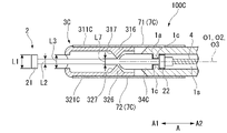
- FIG. 17 is a cross-sectional view of the distal end portion of the treatment instrument 100C.
- the forceps (jaws) 3C are made of conductive metal and function as high-frequency electrodes for applying high-frequency current to living tissue.
- the forceps 3C has a first forceps piece 31C, a second forceps piece 32C, and a connecting portion 34C.
- FIG. 18 is a cross-sectional view of the forceps 3C etc. taken along line YY in FIG.
- the first forceps piece 31C and the second forceps piece 32C are connected at a connecting portion 34C provided on the proximal end side A2, and are provided so as to be openable and closable toward the distal end side A1.
- the connecting portion 34C rotatably connects the first forceps piece 31C and the second forceps piece 32C.
- the base end side of the connecting portion 34C is housed inside the distal end 1a of the sheath 1. As shown in FIG.
- the first forceps piece 31C includes a first concave bottom portion 311C, a first arcuate edge portion 312C provided at a position facing the second forceps piece 32C, and a first concave bottom portion 311C provided on the inner peripheral surface of the first forceps piece 311C. and a convex engaging portion 316 .
- the first concave bottom portion 311C is the same member as the first concave bottom portion 311 of the first embodiment except that it is formed from the distal end to the proximal end of the first forceps piece 31C.
- the first arcuate edge portion 312C is the opening edge of the first concave bottom portion 311C, and is the same member as the first arcuate edge portion 312 of the first embodiment.
- the first convex engaging portion 316 is a convex member provided on the inner peripheral surface of the first concave bottom portion 311C facing the second forceps piece 32C and on the distal end side of the connecting portion 34C.
- the first convex engaging portion 316 has a first engaging surface (receiving portion) 317 that engages with the electrode portion 21 .
- the first engagement surface 317 In the closed state in which the first forceps piece 31C and the second forceps piece 32C are closed, the first engagement surface 317 is inclined with respect to the central axis O3 in the longitudinal direction A of the forceps 3C, and is proximal from the distal end side A1.
- the end side A2 is closer to the central axis O3.
- the second forceps piece 32C includes a second concave bottom portion 321C, a second arcuate edge portion 322C provided at a position facing the first forceps piece 31C, and a second edge portion 322C provided on the inner peripheral surface of the second concave bottom portion 321C. and a two convex engaging portion 326 .
- the second concave bottom portion 321C is the same member as the second concave bottom portion 321 of the first embodiment except that it is formed from the distal end to the proximal end of the second forceps piece 32C.
- the second arcuate edge portion 322C is the opening edge of the second concave bottom portion 321C, and is the same member as the second arcuate edge portion 322 of the first embodiment.
- the second convex engaging portion 326 is a convex member provided on the inner peripheral surface of the second concave bottom portion 321C facing the first forceps piece 31C and on the distal end side of the connecting portion 34C.
- the second convex engaging portion 326 has a second engaging surface 327 that engages with the electrode portion 21 .
- the second engaging surface (receiving portion) 327 is inclined with respect to the central axis O3 in the longitudinal direction A of the forceps 3C, and the distal end
- the base end side A2 is closer to the central axis O3 than the side A1.
- the first convex engaging portion 316 and the second convex engaging portion 326 are arranged on both sides of the central axis O3.
- the shortest length L7 between the first convex engaging portion 316 and the second convex engaging portion 326 is longer than the length L2 in the radial direction R of the rod body 20 and Shorter than length L1. Therefore, the rod body 20 can move back and forth along the longitudinal direction A between the first convex engagement portion 316 and the second convex engagement portion 326 .
- the electrode portion 21 passes between the first convex engaging portion 316 and the second convex engaging portion 326, the first convex engaging portion 316 and the second convex engaging portion 326 are engaged. match.
- the leaf spring 7C has a first leaf spring 71 and a second leaf spring 72, as shown in FIGS.
- the first leaf spring 71 is attached to the sheath 1 and the first forceps piece 31C.
- the first plate spring 71 is attached so as to be flat when the first forceps piece 31C and the second forceps piece 32C are closed. Therefore, the first plate spring 71 urges the first forceps piece 31C to the closed state with a restoring force.
- the second leaf spring 72 is attached to the sheath 1 and the second forceps piece 32C.
- the second leaf spring 72 is attached so as to be flat when the first forceps piece 31C and the second forceps piece 32C are closed. Therefore, the second leaf spring 72 urges the second forceps piece 32C to the closed state with a restoring force.
- FIG. 19 is a cross-sectional view of the distal end portion of the treatment instrument 100C with the electrode portion 21 retracted.
- the electrode section 21 engages the first engaging surface 317 and the second engaging surface 327 .
- the electrode portion 21 pushes the first convex engagement portion 316 and the second convex engagement portion 326 outward in the radial direction R.
- the electrode portion 21 engages with the first engaging surface 317 and the second engaging surface 327, the electrode portion 21 functions as a “butting portion” with respect to the first convex engaging portion 316 and the second convex engaging portion 326. do.
- the first forceps piece 31C and the second forceps piece 32C change from the closed state to the open state against the restoring force of the plate spring 7C.
- the operator can open the first forceps piece 31C and the second forceps piece 32C by retracting the rod 2, as in the first embodiment. Further, the operator can close the first forceps piece 31C and the second forceps piece 32C by retracting the rod 2 as in the first embodiment.
- the operator can perform incision/dissection treatment and hemostatic treatment with the treatment instrument 100C, as in the first embodiment.
- incision/dissection treatment and hemostatic treatment can be performed, and switching operation between the rod 2 for performing the incision/dissection treatment and the forceps 3C for performing hemostatic treatment is easy.
- the operator can switch between the rod 2 for performing the incision/ablation treatment and the forceps 3C for performing the hemostatic treatment only by moving the rod 2 forward and backward.
- FIG. 20 is a cross-sectional view of the distal end portion of the treatment instrument 100D.
- the treatment instrument 100D is used as an endoscope treatment system together with the endoscope 200, like the treatment instrument 100 of the first embodiment.
- the treatment instrument 100D is a treatment instrument capable of performing an incision/stripping treatment and a hemostatic treatment.
- the treatment instrument 100D includes a sheath 1D, a rod 2, forceps (jaws) 3B, an operation wire 4, an operation section 5, and a tube 6D.
- the sheath 1D is the same member as the sheath 1 of the first embodiment except that it has a slit 13 on the outer periphery of the tip 1a.
- the slit 13 is formed along the longitudinal direction A and penetrates from the inner space 1s of the sheath 1D to the outer space.
- the tube (sleeve) 6D has a tube main body 64 and a tube fixing member 65.
- the tube main body 64 is formed in a cylindrical shape and can accommodate the closed forceps 3B.
- a proximal end portion 64b of the tube main body 64 is fitted to the outer peripheral portion of the distal end 1a of the sheath 1D.
- the tube fixing member 65 is a member that connects the base end portion 64b of the tube main body 64 and the operation wire 4 . Since the tube fixing member 65 is arranged so as to pass through the slit 13, it can connect the tube body 64 outside the sheath 1D and the operation wire 4 inside the sheath 1D.
- FIG. 21 is a cross-sectional view of the distal end portion of the treatment instrument 100D with the electrode portion 21 retracted.
- the tube fixing member 65 and the tube main body 64 connected to the operation wire 4 also retract.
- the connecting portion 34B of the forceps 3B is biased so that the first forceps piece 31B and the second forceps piece 32B are in an open state. Therefore, when the tube main body 64 retreats with respect to the forceps 3B, the first forceps piece 31B and the second forceps piece 32B change from the closed state to the open state.
- the tube main body 64 accommodates the forceps 3B, and the first forceps piece 31 and the second forceps piece 32 change from the open state to the closed state.
- the operator can open the first forceps piece 31 and the second forceps piece 32 by retracting the rod 2 as in the first embodiment. Further, the operator can close the first forceps piece 31 and the second forceps piece 32 by retracting the rod 2 in the same manner as in the first embodiment.
- the operator can perform incision/dissection treatment and hemostatic treatment with the treatment instrument 100D, as in the first embodiment.
- incision/dissection treatment and hemostatic treatment can be performed, and switching operation between the rod 2 for performing the incision/dissection treatment and the forceps 3B for performing hemostatic treatment is easy.
- the operator can switch between the rod 2 for performing the incision/dissecting treatment and the forceps 3B for performing the hemostatic treatment only by moving the rod 2 forward and backward.
- the present invention can be applied to treatment tools used for hemostatic treatment.
- endoscope treatment system 200 endoscopes 100, 100B, 100C, 100D treatment instruments 1, 1B, 1D sheaths 2, 2A rod 20 rod body 21 electrode portion 22 stopper 23 abutment portions 3, 3B, 3C forceps (jaws) 31, 31B, 31C first forceps pieces 32, 32B, 32C second forceps piece 33 through holes 34, 34B, 34C connecting portion 315 first base end support portion (receiving portion) 317 first engagement surface (receiving portion) 325 second proximal support (receiving portion) 327 second engagement surface (receiving portion) 4 Operation wire 5 Operation part 51 Operation part body 52 Slider 53 Power supply connector 6 Holding tube (sleeve) 60 rod through hole 61 first forceps piece through hole 62 second forceps piece through hole 63 tip wall (receiving portion) 6D tube 64 tube main body 65 tube fixing member 7 spring 7C leaf spring
Landscapes
- Health & Medical Sciences (AREA)
- Surgery (AREA)
- Life Sciences & Earth Sciences (AREA)
- Engineering & Computer Science (AREA)
- Biomedical Technology (AREA)
- Public Health (AREA)
- Nuclear Medicine, Radiotherapy & Molecular Imaging (AREA)
- Veterinary Medicine (AREA)
- General Health & Medical Sciences (AREA)
- Heart & Thoracic Surgery (AREA)
- Medical Informatics (AREA)
- Molecular Biology (AREA)
- Animal Behavior & Ethology (AREA)
- Physics & Mathematics (AREA)
- Otolaryngology (AREA)
- Plasma & Fusion (AREA)
- Ophthalmology & Optometry (AREA)
- Surgical Instruments (AREA)
Priority Applications (3)
| Application Number | Priority Date | Filing Date | Title |
|---|---|---|---|
| JP2022576937A JP7459311B2 (ja) | 2021-01-25 | 2021-01-25 | 処置具 |
| CN202180090542.0A CN116761561B (zh) | 2021-01-25 | 2021-01-25 | 处置器具 |
| PCT/JP2021/002444 WO2022157974A1 (ja) | 2021-01-25 | 2021-01-25 | 処置具 |
Applications Claiming Priority (1)
| Application Number | Priority Date | Filing Date | Title |
|---|---|---|---|
| PCT/JP2021/002444 WO2022157974A1 (ja) | 2021-01-25 | 2021-01-25 | 処置具 |
Publications (1)
| Publication Number | Publication Date |
|---|---|
| WO2022157974A1 true WO2022157974A1 (ja) | 2022-07-28 |
Family
ID=82548652
Family Applications (1)
| Application Number | Title | Priority Date | Filing Date |
|---|---|---|---|
| PCT/JP2021/002444 Ceased WO2022157974A1 (ja) | 2021-01-25 | 2021-01-25 | 処置具 |
Country Status (3)
| Country | Link |
|---|---|
| JP (1) | JP7459311B2 (https=) |
| CN (1) | CN116761561B (https=) |
| WO (1) | WO2022157974A1 (https=) |
Citations (2)
| Publication number | Priority date | Publication date | Assignee | Title |
|---|---|---|---|---|
| US5704925A (en) * | 1994-02-09 | 1998-01-06 | Aerztliche Mechanik Udo Lindeke & Sohn | Medical instrument for injecting liquids into a hollow organ and/or drawing off liquids from a hollow organ, in particular a bile duct |
| WO2019206042A1 (zh) * | 2018-04-23 | 2019-10-31 | 南京微创医学科技股份有限公司 | 一种多功能高频电切开刀 |
Family Cites Families (10)
| Publication number | Priority date | Publication date | Assignee | Title |
|---|---|---|---|---|
| JP4838945B2 (ja) * | 2001-05-10 | 2011-12-14 | オリンパス株式会社 | 内視鏡用処置具および内視鏡用処置具の操作部 |
| EP1696801A1 (en) * | 2003-12-23 | 2006-09-06 | Cook Urological Inc. | Back loading endoscopic instruments |
| WO2008008457A2 (en) * | 2006-07-13 | 2008-01-17 | Bovie Medical | Surgical sealing and cutting apparatus |
| JP5048391B2 (ja) * | 2007-04-27 | 2012-10-17 | 直久 矢作 | 内視鏡用処置具 |
| US20100185196A1 (en) * | 2009-01-21 | 2010-07-22 | Satomi Sakao | Medical treatment apparatus, treatment instrument and treatment method for living tissue using energy |
| CN102144932B (zh) * | 2011-05-06 | 2012-09-12 | 王宝根 | 内镜下微创剥离刀 |
| WO2015056937A1 (ko) * | 2013-10-16 | 2015-04-23 | 국립암센터 | 내시경용 주사장치 |
| EP3335656B1 (en) * | 2014-08-20 | 2019-06-12 | Gyrus ACMI, Inc. d/b/a/ Olympus Surgical Technologies America | Multi-mode combination electrosurgical device |
| CN113274123B (zh) * | 2016-01-11 | 2024-06-14 | 捷锐士阿希迈公司(以奥林巴斯美国外科技术名义) | 具有组织止动件的夹钳 |
| CN212234520U (zh) * | 2020-01-22 | 2020-12-29 | 北京龙淼医疗器械有限公司 | 连续取样活检钳 |
-
2021
- 2021-01-25 JP JP2022576937A patent/JP7459311B2/ja active Active
- 2021-01-25 CN CN202180090542.0A patent/CN116761561B/zh active Active
- 2021-01-25 WO PCT/JP2021/002444 patent/WO2022157974A1/ja not_active Ceased
Patent Citations (2)
| Publication number | Priority date | Publication date | Assignee | Title |
|---|---|---|---|---|
| US5704925A (en) * | 1994-02-09 | 1998-01-06 | Aerztliche Mechanik Udo Lindeke & Sohn | Medical instrument for injecting liquids into a hollow organ and/or drawing off liquids from a hollow organ, in particular a bile duct |
| WO2019206042A1 (zh) * | 2018-04-23 | 2019-10-31 | 南京微创医学科技股份有限公司 | 一种多功能高频电切开刀 |
Also Published As
| Publication number | Publication date |
|---|---|
| CN116761561A (zh) | 2023-09-15 |
| CN116761561B (zh) | 2026-04-14 |
| JPWO2022157974A1 (https=) | 2022-07-28 |
| JP7459311B2 (ja) | 2024-04-01 |
Similar Documents
| Publication | Publication Date | Title |
|---|---|---|
| US9775670B2 (en) | Saber tooth harvester | |
| CN101278859B (zh) | 内窥镜用处理器具 | |
| JP6614456B2 (ja) | 高周波鉗子 | |
| US7731714B2 (en) | Instrument for endoscope and instrument system for endoscope | |
| JP5792416B1 (ja) | 内視鏡処置システム | |
| US20100198248A1 (en) | Surgical dissector | |
| CN105163678A (zh) | 内窥镜用处理器具 | |
| US9277959B2 (en) | Medical treatment instrument | |
| CN217338657U (zh) | 内窥镜用处置器具 | |
| JP7459311B2 (ja) | 処置具 | |
| US20240197156A1 (en) | Treatment instrument for endoscope | |
| US20230136593A1 (en) | Treatment tool for endoscope | |
| JP7592756B2 (ja) | 処置具 | |
| JP7712348B2 (ja) | 内視鏡用処置具および内視鏡用処置具システム | |
| KR102212719B1 (ko) | 내시경용 처치장치 | |
| CN116531080B (zh) | 内窥镜用处置器具 | |
| JP2025048787A (ja) | 内視鏡用処置具 | |
| JP2024145743A (ja) | 内視鏡用処置具 | |
| WO2024202400A1 (ja) | 内視鏡用処置具 |
Legal Events
| Date | Code | Title | Description |
|---|---|---|---|
| 121 | Ep: the epo has been informed by wipo that ep was designated in this application |
Ref document number: 21921082 Country of ref document: EP Kind code of ref document: A1 |
|
| WWE | Wipo information: entry into national phase |
Ref document number: 202180090542.0 Country of ref document: CN |
|
| ENP | Entry into the national phase |
Ref document number: 2022576937 Country of ref document: JP Kind code of ref document: A |
|
| NENP | Non-entry into the national phase |
Ref country code: DE |
|
| 122 | Ep: pct application non-entry in european phase |
Ref document number: 21921082 Country of ref document: EP Kind code of ref document: A1 |