WO2022154128A1 - コミュニケーション装置及びコミュニケーションプログラム並びに記憶媒体 - Google Patents
コミュニケーション装置及びコミュニケーションプログラム並びに記憶媒体 Download PDFInfo
- Publication number
- WO2022154128A1 WO2022154128A1 PCT/JP2022/001637 JP2022001637W WO2022154128A1 WO 2022154128 A1 WO2022154128 A1 WO 2022154128A1 JP 2022001637 W JP2022001637 W JP 2022001637W WO 2022154128 A1 WO2022154128 A1 WO 2022154128A1
- Authority
- WO
- WIPO (PCT)
- Prior art keywords
- image
- participant
- face
- participants
- movement
- Prior art date
- Legal status (The legal status is an assumption and is not a legal conclusion. Google has not performed a legal analysis and makes no representation as to the accuracy of the status listed.)
- Ceased
Links
Images















Classifications
-
- G—PHYSICS
- G06—COMPUTING OR CALCULATING; COUNTING
- G06F—ELECTRIC DIGITAL DATA PROCESSING
- G06F3/00—Input arrangements for transferring data to be processed into a form capable of being handled by the computer; Output arrangements for transferring data from processing unit to output unit, e.g. interface arrangements
- G06F3/01—Input arrangements or combined input and output arrangements for interaction between user and computer
-
- H—ELECTRICITY
- H04—ELECTRIC COMMUNICATION TECHNIQUE
- H04L—TRANSMISSION OF DIGITAL INFORMATION, e.g. TELEGRAPHIC COMMUNICATION
- H04L67/00—Network arrangements or protocols for supporting network services or applications
-
- H—ELECTRICITY
- H04—ELECTRIC COMMUNICATION TECHNIQUE
- H04M—TELEPHONIC COMMUNICATION
- H04M3/00—Automatic or semi-automatic exchanges
- H04M3/42—Systems providing special services or facilities to subscribers
- H04M3/56—Arrangements for connecting several subscribers to a common circuit, i.e. affording conference facilities
-
- H—ELECTRICITY
- H04—ELECTRIC COMMUNICATION TECHNIQUE
- H04N—PICTORIAL COMMUNICATION, e.g. TELEVISION
- H04N7/00—Television systems
- H04N7/14—Systems for two-way working
-
- H—ELECTRICITY
- H04—ELECTRIC COMMUNICATION TECHNIQUE
- H04N—PICTORIAL COMMUNICATION, e.g. TELEVISION
- H04N7/00—Television systems
- H04N7/14—Systems for two-way working
- H04N7/15—Conference systems
Definitions
- the present invention relates to a communication device or the like for displaying a participant at another point on a screen to perform a video conference or a conversation.
- this type of communication device there is a video conference device in which a plurality of terminal devices are connected by a network and an image of a participant from an imaging device installed in the terminal device is displayed on the display screen of each terminal device to hold a conference. ..
- the conventional video conference device for example, as shown in FIG. 1 of Patent Document 1, the front faces of a plurality of participants are arranged and displayed in a grid pattern on the display screen of the terminal device.
- Patent Document 1 a device that simply enumerates and displays the front faces as in Patent Document 1
- Patent Document 2 a profile can be imaged and displayed by using a plurality of image pickup devices.
- the techniques such as Patent Document 1 and Patent Document 2 are aimed exclusively at estimating the dialogue partner and matching the line of sight, for example, moving the face to look into the profile of the partner or watching the presentation next to each other. It is not always envisioned that the line of sight does not have to be aligned, such as talking to a person or looking over other participants. Therefore, it is difficult to convey the feeling of being in an actual conference room or venue.
- the present invention provides a communication device or the like that can give a feeling of being there by changing the appearance and the appearance of the surroundings according to the movement of one's face.
- the purpose is to provide.
- the device of the present invention is a communication device that displays images of a plurality of participants on a terminal device, and includes a plurality of images including facial images of different directions for each of the plurality of participants.
- the acquisition unit that acquires the image
- the motion detection unit that detects the movement of at least one of the participants' faces from the facial image acquired by the acquisition unit, and the movement of the participant's face detected by the motion detection unit
- An image selection unit that selects images of the faces of other participants, and an image generation that generates an image for displaying at least the images of the faces of other participants on the terminal device from the images selected by the image selection unit. It has a part and.
- the communication device of this aspect the appearance of other participants can be changed according to the movement of one's face, so that a feeling of being there can be obtained.
- a virtual conference room for arranging a plurality of participants and a virtual conference room storage unit for storing the positions of the plurality of participants in the virtual conference room
- the video generation unit is a virtual conference.
- the position where the participant is displayed is specified according to the position of the participant in the virtual conference room, so that the position of the other participant looks as if it is in the actual conference room position. You can have a video conference or conversation at.
- the video selection unit selects a video with a face orientation according to the position of a participant in a virtual conference room.
- a participant next to himself / herself can display a profile image, so that other participants can see the video conference or conversation as if they were in an actual conference room. It can be performed.
- the image selection unit selects the display range of the virtual conference room according to the movement of the participant's face detected by the motion detection unit, and the image generation unit is among a plurality of participants. Generate an image for displaying the participants included in the display range on the terminal device.
- the desired range of the virtual conference room can be displayed by moving one's face. For example, if you want to see only the participants on the right side of the table, you can move your face to the right so that only the participants on your right side can see. It is also possible to display only the participant and have a conversation only with the participant by moving the face to the participant who is talking, just as if he / she goes near the participant and has a conversation in the actual conference room. As a result, you can get a sense of realism as if you were having a conversation in an actual conference room.
- the motion detection unit detects whether the face direction of at least one of the participants is front, right, or left from the face image acquired by the acquisition unit, and selects the image. If the face orientation of the participant detected by the motion detection unit is front, the display range of the virtual conference room should not include the images of other participants located on the right and left sides of the participant. If the face of the participant detected by the motion detection unit is facing right, the display range of the virtual conference room should include the images of other participants located on the right side of the participant, and the motion detection unit should be used. If the detected participant's face is facing left, include images of other participants located to the left of that participant.
- the image selection unit selects the image with the face orientation corresponding to the changed position, and the image generation unit changes the position. Generates a video that specifies the position to display the participant according to the position. According to this aspect, even if the seats are moved in the virtual conference room, the appearance similar to that of the actual conference room can be realized in the video conference or the conversation, so that the sense of presence can be enhanced.
- a voice selection unit that selects the voice of another participant according to the movement of the participant's face detected by the motion detection unit, and another voice selection unit based on the voice selected by the voice selection unit. It is provided with a voice generation unit that generates voice for outputting the voice of the participant of the above from the terminal device. According to this aspect, it is possible to select the sound according to the movement of the participant's face as the sound according to the video. For example, it is possible to select and output the sound of only the participants whose images are displayed according to the movement of the face.
- the acquisition unit acquires a face image in a different direction and a surrounding image in a different direction for each of the plurality of participants
- the image selection unit is a participant detected by the motion detection unit.
- the image of the face orientation of other participants and the surrounding image are selected according to the movement of the face of the other participant
- the image generation unit selects at least the image of the face of another participant and the surroundings from the images selected by the image selection unit.
- the face orientation image and the surrounding image of another participant are selected according to the movement of the participant's face from the face image of the different orientation and the surrounding image of the different orientation. If you move, the surrounding image will also move and be displayed in conjunction with the movement of the face. As a result, the surrounding image can be moved so that the invisible part can be seen just by moving the face, so that you can experience the feeling of being there.
- the motion detection unit detects the movement of the face and the direction of the face as the movement of the participant's face, and the image selection unit selects the surrounding image according to the movement of the face, and the face is selected.
- the display range of the surrounding image is selected according to the orientation of the image, and the image generation unit generates an image for displaying the surrounding image on the terminal device in the display range selected by the image selection unit.
- the surrounding image is selected according to the movement of the participant's face, and the display range of the surrounding image is selected according to the orientation of the face. Therefore, if the face is moved, it is linked to the movement of the face.
- the display range of the surrounding image can also be changed. As a result, the display range of the surrounding image can be changed so that the invisible part can be seen just by moving the face, so that the user can experience the feeling of being there.
- a virtual conference room storage unit for arranging a plurality of participants and a virtual conference room storage unit for storing the positions of the plurality of participants and the positions of surrounding images in the virtual conference room.
- the selection unit changes the display position of the participant according to the orientation of the surrounding image selected according to the movement of the participant's face. According to this aspect, by changing the display position of the participant according to the orientation of the surrounding image selected according to the movement of the face of the participant, it is possible to display as if the surrounding image is being viewed from the display position. Therefore, it is possible to have a realistic experience as if you were there.
- the storage medium of the present invention is a computer-readable storage medium that stores a communication program that causes a computer to perform video processing performed by a communication device, and the video processing is performed by a plurality of participants.
- a step of acquiring a plurality of images including images of faces having different orientations for each, a step of detecting the movement of the face of at least one of the participants from the acquired images of the face, and a step of detecting the movement of the face of the participant. Includes a step of selecting an image of the face orientation of another participant according to the above, and a step of generating an image for displaying at least the image of the face of another participant on the terminal device from the selected image. ..
- Video processing can be executed by reading and executing the program of the storage medium of this embodiment by a computer, and the computer can function as a communication device.
- the program of the present invention is a communication program for causing a computer to perform video processing performed by a communication device, and the video processing includes images of faces in different directions for each of a plurality of participants.
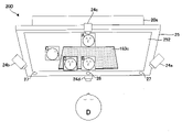
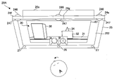
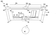
- FIG. 6 is a schematic view of the terminal device of FIG. 6 as viewed from the front. It is the figure which looked at the terminal device of FIG. 6 from the top, and is the figure which shows the image example from the image pickup device.
- FIG. 3 is a schematic view of the terminal device of FIG. 34 as viewed from the front. It is the figure which looked at the terminal apparatus of FIG. 34 from the top, and is the figure which shows the specific example of the ambient image from each image pickup apparatus. It is a block diagram of the communication device and the terminal device of the 4th embodiment. It is a figure which shows the specific example of the virtual meeting room configuration information of FIG. 36. It is a figure which shows the specific example of the participant information of FIG.
- FIG. 36 It is a figure which shows the specific example of the virtual conference room display information of FIG. 36. It is a figure which shows the image example from the image pickup apparatus 24g of a participant B, (a) is an omnidirectional image, (b) is an output image generated from an omnidirectional image. It is a figure which shows the display image which a participant A can see from the front without moving a face. It is a figure which shows the image example from the image pickup apparatus 24f of a participant B, (a) is an omnidirectional image, (b) is an output image generated from an omnidirectional image. It is a figure which shows the display image which a participant A appears by moving a face to the left.
- FIG. 1 It is a figure which shows the image example from the image pickup apparatus 24e of a participant B, (a) is an omnidirectional image, (b) is an output image generated from an omnidirectional image. It is a figure which shows the display image which a participant A appears by moving a face to the right. It is a figure which shows the change of the display range when a participant A turns his face to the left. It is a figure which shows the display image which the participant A looks at with his face turned to the left. It is a figure which shows the change of the display range when a participant A turns his face to the right. It is a figure which shows the display image which a participant A looks at with a face to the right.
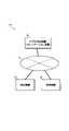
- FIG. 1 is a diagram showing a configuration of a video conference system 100 according to the first embodiment.
- the video conference system 100 of FIG. 1 includes a video conference device 10 and a terminal device 20.
- the video conference system 100 displays a plurality of participants on the screen of the terminal device 20 to perform a video conference (web conference, video conference).
- the video conference device 10 of the present embodiment changes the appearance of other participants according to the movement of one's face (in conjunction with the movement of one's face) and displays it on the screen. Since the appearance of other participants changes according to the movement of one's face (movement of face, orientation of face, etc.), it is possible to have a meeting with a sense of reality as if you were there.
- the video conference device 10 of the first embodiment illustrates a case where the video conference device 10 is configured by a server computer whose client is the terminal device 20.
- the video conference device 10 may be configured to perform distributed processing by a plurality of devices, or may be configured by a plurality of virtual machines provided in one server device. Further, the video conference device 10 may be configured by a personal computer or a cloud server.
- the video conference device 10 and the terminal device 20 are configured to be able to communicate with each other via a network N such as the Internet.
- the terminal device 20 is an information processing device used by the user.
- the terminal device 20 is, for example, a mobile terminal such as a smartphone, a tablet, a PDA (Personal Digital Assistant), a desktop personal computer, a notebook personal computer, or the like. Although the case where two terminal devices 20 are connected to the network N is illustrated, three or more terminal devices 20 may be connected. Each terminal device 20 is used by a participant at a different point, but may include one used by another participant at the same point.
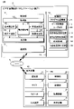
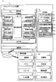
- FIG. 2 is a block diagram showing a specific configuration example of the video conference device 10 (communication device) and the terminal device 20 of FIG.
- the video conference device 10 includes a communication unit 11, a control unit 12, and a storage unit 14.
- the communication unit 11, the control unit 12, and the storage unit 14 are each connected to the bus line 10L, and information (data) can be exchanged with each other.
- the communication unit 11 is connected to the network N by wire or wirelessly, and transmits / receives information (data) to / from the terminal device 20.
- the communication unit 11 functions as a communication interface for the Internet or an intranet, and can perform communication using, for example, TCP / IP.
- the control unit 12 comprehensively controls the entire video conference device 10.
- the control unit 12 is composed of an integrated circuit such as an MPU (Micro Processing Unit).
- the control unit 12 includes a CPU (Central Processing Unit), a RAM (Random Access Memory), and a ROM (Read Only Memory).
- the control unit 12 loads a necessary program into the ROM and executes the program using the RAM as a work area to perform various processes (video conference processing, etc.).
- the storage unit 14 is a computer-readable storage medium that stores various programs executed by the control unit 12, data used by these programs, and the like.
- the storage unit 14 is composed of a storage device such as a hard disk, an optical disk, or a magnetic disk.
- the configuration of the storage unit 14 is not limited to these, and the storage unit 14 may be configured by a semiconductor memory such as a RAM or a flash memory.
- the storage unit 14 can be configured by SSD (Solid State Drive).
- the storage unit 14 includes a program storage unit 15, a data storage unit 16, a virtual conference room storage unit 18, and the like.
- the program storage unit 15 stores various programs executed by the control unit 12.
- the control unit 12 reads a necessary program from the program storage unit 15 and executes various processes.
- user information 161 is stored in the data storage unit 16.
- the user information 161 includes a user ID, a company name, a name, and the like registered in advance.
- the user information 161 is not limited to this.
- the virtual conference room storage unit 18 stores preset virtual conference room configurations, position information of participants in the virtual conference room, and the like. Specifically, the virtual conference room storage unit 18 stores virtual conference room configuration information 181, participant information 182, virtual conference room display information 183, and the like. In addition, the virtual conference room storage unit 18 stores image data such as a table 183c and a whiteboard 183d as conference room components to be displayed in the virtual conference room. Images and moving images for presentation can also be displayed on the whiteboard 183d. In this specification, the virtual conference room may be a virtual conversation room.
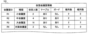
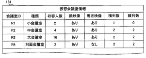
- the virtual conference room configuration information 181 is the configuration information of the virtual conference room for arranging the images of the participants to be displayed on each terminal device 20, and includes, for example, a data table as shown in FIG. Specifically, the type of virtual conference room, the number of people accommodated, the presence / absence of a table 183c, the presence / absence of a whiteboard 183d, the number of columns and rows in which participants can be displayed, and the like.
- configuration information of a plurality of virtual conference rooms different in the number of participants, the number of columns in which the participants are arranged, the presence / absence of the display of the table 183c, and the like are stored.
- FIG. 3 illustrates a small conference room R1, a medium conference room R2, a large conference room R3, a face-to-face conference room R4, and the like.
- the capacity of the small conference room R1, the medium conference room R2, and the large conference room R3 is different, and the appearance of the participants differs between the face-to-face conference room R4 and the other conference rooms.
- images of oneself and other participants are displayed in a frame around the table 183b as shown in FIG. 6, which will be described later. It is also possible to hide the table 183b. In the two-person meeting room R4, neither the table 183b nor oneself is displayed, and only the image of the other party is displayed.
- the virtual conference room is not limited to the one shown in the figure.
- the user can change the type of virtual conference room, the number of people that can be accommodated, the presence or absence of a table 183c, the presence or absence of a whiteboard 183d, the number of columns and rows that can display participants, and the like. It may be possible to set and set.
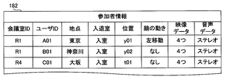
- Participant information 182 stores information on participants participating in the conference, and is composed of, for example, a data table as shown in FIG. Specifically, the participant information 182 includes the conference room ID, user ID, point, presence / absence of entry, presence / absence of leaving, and the position of the participant on the virtual conference room (row y01, column t01, etc.). Information such as the movement of the participant's face, the number of video data, and the type of audio data can be mentioned.
- the video data and audio data are data received from the terminal device 20, and the number of video data is, for example, four if it is front, right, left, or bottom.
- the type of audio data received from the terminal device 20 is stereo audio.
- Participant information 182 is not limited to the above-mentioned information, and for example, an IP address, a screenshot image, or the like may be stored.
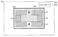
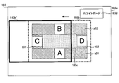
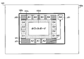
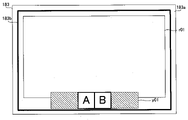
- the virtual conference room display information 183 is the display information of the virtual conference room in which each participant enters. For example, as shown in FIG. 5, in the virtual conference room display information 183, the row in which each participant is arranged, the position of each participant (the position of the frame in which the image of the participant is fitted), the conference such as the table 183c and the whiteboard 183d, etc. The position of the element, the display range 183b of the virtual conference room, and the like are included.
- the virtual conference room display information 183 is provided for each type of the virtual conference room of the virtual conference room configuration information 181 of FIG. Which virtual conference room to use can be set in advance by the host participant.
- FIG. 5 illustrates a case where two participants A and B use the virtual conference room of the small conference room R1 of FIG.
- the outer frame 183a shows the entire virtual conference room.
- the thick frame inside shows the display range 183b.
- the small conference room R1 in FIG. 3 has a capacity of two people, a table, two rows, and two columns.
- the table 183c is arranged in the center.
- the lower row of the table 183c corresponds to the row y01
- the upper row of the table 183c corresponds to the row y02.
- the left column of the table 183c corresponds to the column t01
- the right column of the table 183c corresponds to the column t02.
- the positions of the table 183c, the whiteboard 183d, the columns, the rows, etc. shown in FIG. 5 may be preset, or may be used by the host participant by changing the positions. ..
- FIG. 6 which will be described later, illustrates a case where the image of the participant A is fitted in the A frame and the image of the participant B is fitted in the B frame by using the small conference room R1.
- the display of the terminal device 20 it is possible to select in advance whether to display the virtual conference room in a plane or in a three-dimensional manner.
- the display range 183b of FIG. 5 is displayed as it is on the display screen 252, and when the three-dimensional display is selected, the table 183c or the like is three-dimensionally displayed as shown in FIG. In FIG.
- the display range 183b is the range including the column in which the participants are arranged and the table 183c. In FIG. 5, the whiteboard 183d is not displayed because it is not included in the display range 183b. If so, the display range 183b can be adjusted to include the whiteboard 183d from the beginning or during the meeting.
- the control unit 12 of FIG. 2 includes an acquisition unit 121, a motion detection unit 122, a video selection unit 123, a video generation unit 124, a voice selection unit 125, a voice generation unit 126, and an output unit 127.
- Each component of the control unit 12 may be composed of a physical circuit or a program that can be executed by the CPU.
- the configuration of the control unit 12 is not limited to the configuration shown in FIG.
- the acquisition unit 121 receives a plurality of video data and audio data of the participants imaged by the image pickup device 24 for each terminal device 20 via the communication unit 11. Specifically, the acquisition unit 121 receives video data including facial images of each participant in different directions (for example, front, right side, left side, upper side, lower side, etc.) and stereo audio data (left side audio, right side audio). do.
- the acquisition unit 121 does not care which image pickup device 24 is used to capture the image, but in addition to the image of the front face, if the other party who sees himself / herself is there, he / she should see his / her own image when the other party moves his / her face.
- a face image (right side, left side, upper side, lower side, etc.) is also input. For example, when moving the face left and right to change the image of another participant, the image from the right side of the face (right face image) and the image from the left side (left face image) are input.
- the motion detection unit 122 detects the movement of the participant's face from the video data acquired by the acquisition unit 121.
- the motion detection unit 122 also detects whether or not there is a movement of the participant's face.
- Examples of the "face movement” here include face movement (change in face position) and face rotation (change in face orientation).
- the motion detection unit 122 can detect movement of the face (change in the position of the face) in, for example, the horizontal direction (horizontal direction), the vertical direction (vertical direction), and the front-back direction.
- the motion detection unit 122 may also be able to detect rotation of the face (change in face orientation) such as rightward, leftward, upward, and downward.
- the motion detection unit 122 of the first embodiment detects that there is movement of the face, it also detects in which direction the face has moved in the horizontal direction (right direction, left direction) or the vertical direction (upward direction, downward direction). do.
- the motion detection unit 122 may detect the movement of the face from the image of the front of the face, or may detect the movement of the face from the image of another direction (the image of the face facing right or the image of the face facing left). ..
- the face part is recognized from the image of the front of the face
- the direction of the face (the direction of the nose may be) is vectorized
- the movement of the face (change in the position of the face) is detected from the change in the position of the vector.
- the rotation of the face (change in the orientation of the face) may be detected from the change in the angle of the vector.
- the movement of the face from the image of the image pickup device 24 is detected from the image of the image pickup device 24 by using a learned model in which the movement of the face from the image of the image pickup device 24 is machine-learned by AI (artificial intelligence) or the like. You may try to do it.
- AI artificial intelligence
- the detection of facial movement is not limited to the above method, and any method may be used as long as it can be detected from the facial image.
- the image selection unit 123 displays images of faces in different directions acquired by the acquisition unit 121 for each participant on the terminal device 20 according to the movement of the face detected by the motion detection unit 122. Select a video. For example, in an actual meeting, if you have someone to meet you, you should be able to see the right side of the other person's face by moving your face to the left. Therefore, for example, when the motion detection unit 122 detects the movement of the face of the participant to the left (movement to the left), the image selection unit 123 acquires the image of another participant to be displayed at the face-to-face position of the participant.
- the image on the right side of the face is selected from the images of the faces in different directions (front, right side, left side, upper side, lower side, etc.) acquired in the unit 121.
- the image generation unit 124 fits the image of each participant's face selected by the image selection unit 123 into a predetermined position (position of the face image frame) in the virtual conference room, and generates an output image combined with an image such as a table. do. This allows you to see the images of other participants as if you were moving your face in an actual meeting.
- the voice selection unit 125 selects the voices of other participants according to the movement of the participant's face detected by the motion detection unit 122. For example, in an actual meeting, if you move your face to talk to a participant on the left side, the left side should sound stronger. Therefore, for example, when the motion detection unit 122 detects the movement of the participant's face to the left, the stereo sound acquired by the acquisition unit 121 is used as the voice of another participant to be displayed on the left side of the participant. Select the left voice from the data.
- the voice generation unit 126 generates left and right voices and output voices whose overall volume is adjusted.
- the motion detection unit 122 detects the movement of the participant's face to the left as described above, the volume of the left voice is set to be higher than that of the right voice for the voices of other participants displayed on the left side of the participant. Generate a large output audio.
- the output unit 127 outputs the output video generated by the video generation unit 124 and the output audio generated by the audio generation unit 126 to the communication unit 11 as moving image data (video data).
- the control unit 12 stores and updates the motion detection unit 122 detected facial movements and the like in the participant information 182 of FIG.
- the video selection unit 123 and the audio selection unit 125 may select the video and audio based on the movement of the face of the participant information 182.
- the output video and output audio from the output unit 127 are transmitted to the terminal device 20 as moving image data via the communication unit 11.
- the terminal device 20 displays the received output video on the display screen 252 of the display device 25, and outputs the output sound from the speaker 27.
- the output video and output audio may be Web moving image data.
- the video conference device 10 displays the output video and the output audio as moving image data on the Web, and the terminal device 20 receives the moving image data from the Web and displays it on the browser.
- the terminal device 20 shown in FIG. 2 includes a communication unit 21, a control unit 22, a storage unit 23, an image pickup device 24, a display device 25, a microphone 26, a speaker 27, and an input device 28. Each of these is connected to the bus line 20L, and information (data) can be exchanged with each other.
- the communication unit 21 is connected to the network N by wire or wirelessly, and transmits / receives information (data) to / from the video conference device 10.
- the communication unit 21 functions as a communication interface for the Internet and an intranet, and can perform communication using, for example, TCP / IP.
- the control unit 22 comprehensively controls the entire terminal device 20.
- the control unit 22 is composed of an integrated circuit such as an MPU (Micro Processing Unit).
- the control unit 22 includes a CPU (Central Processing Unit), a RAM (Random Access Memory), and a ROM (Read Only Memory).
- the control unit 22 performs various processes by loading a necessary program into the ROM and executing the program using the RAM as a work area.
- the storage unit 23 is an example of various programs executed by the control unit 22 and a storage medium for storing data used by these programs.
- the storage unit 23 is composed of a storage device such as a hard disk, an optical disk, or a magnetic disk.
- the configuration of the storage unit 23 is not limited to these, and the storage unit 23 may be configured by a semiconductor memory such as a RAM or a flash memory.
- the storage unit 23 can be configured by SSD (Solid State Drive).
- the imaging device 24 is a plurality of cameras that capture the faces of participants from different directions.
- the number of image pickup devices 24 may be two, three, or four or more.
- the image pickup device 24 may be a camera built in the terminal device 20 or an external camera. Further, any camera such as a CCD (Charge Coupled Device) camera, a Web camera, or an IoT camera that can output video may be used.
- CCD Charge Coupled Device
- the display device 25 is a liquid crystal display, an organic EL display, or the like, and displays various information according to instructions from the control unit 22.
- the control unit 22 displays the moving image data received from the video conference device 10 via the communication unit 21 on the display screen 252 of the display device 25.
- the microphone 26 is a stereo microphone that captures the voice of the participants.
- the microphone 26 may be a microphone built in the terminal device 20 or an external microphone.
- the speaker 27 is a stereo speaker, and outputs various sounds and music according to instructions from the control unit 22.
- the speaker 27 may be a speaker built in the terminal device 20 or an external speaker.
- the input device 28 is a keyboard, a mouse, or the like, and receives an operation input from the user and transmits a control signal corresponding to the operation content to the control unit 22.
- the input device 28 may be a touch panel provided on the display device 25.
- the appearance of other participants on the display screen 252 can be changed by the movement of the face without using a mouse or a keyboard.
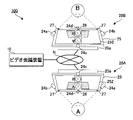
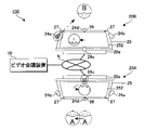
- FIG. 6 is a diagram showing a schematic configuration of the video conference system 100 when there are two participants.
- the video conference system 100 of FIG. 6 is configured by connecting the terminal device 20A of the participant A and the terminal device 20B of the participant B to the server constituting the video conference device 10 by a network N. Since the terminal devices 20A and 20B have the same configuration, elements having the same function will be described with the same reference numerals.
- the terminal devices 20A and 20B in FIG. 6 are personal computers in which the main body 20a and the display device 25 are integrated.
- a microphone 26 is provided in the center and speakers 27 are provided on the left and right sides below the front surface of the display device 25.
- a main body 20a is provided on the back surface of the display device 25.
- the main body 20a includes a communication unit 21, a control unit 22, a storage unit 23, and the like.
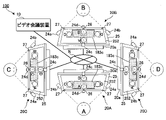
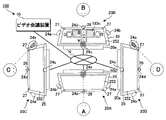
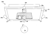
- Four image pickup devices 24a, 24b, 24c, and 24d are provided on the outer periphery of the display device 25.
- the four image pickup devices 24a, 24b, 24c, and 24d are for acquiring images including images of faces in different directions, and are connected to the main body 20a so that the images can be transmitted from the communication unit 21. .. Since the four image pickup devices 24a, 24b, 24c, and 24d have different orientations, not only the face but also the background looks different. Therefore, the background changes depending on which image is selected and displayed, so that the sense of presence can be further
- the image pickup device 24 (24a, 24b, 24c, 24d) does not necessarily have to be installed on the display device 25, and if video data including images of faces in different directions can be acquired, it can be placed in any place such as a wall or a desk. It may be installed. Further, the image pickup device 24 does not necessarily have to be electrically connected to the terminal devices 20A and 20B.
- the image pickup device 24 may be any image pickup device 24 such as a CCD camera, a Web camera, or an IoT camera, as long as video data including images of faces in different directions is transmitted to the video conference device 10 via the network N. May be used. Further, the number of image pickup devices 24 is not limited to four.
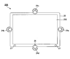
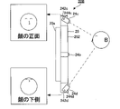
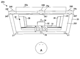
- FIG. 7 is a view seen from the front of the terminal device 20B of FIG. 6 and is a view showing the position of the image pickup device.
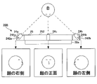
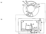
- FIG. 8 is a view of the terminal device 20B of FIG. 7 as viewed from above, and is a diagram showing an example of an image from the image pickup device 24.
- FIG. 9 is a view of the terminal device 20B of FIG. 7 viewed from the left, and is a diagram showing an example of an image from the image pickup device 24. Since the terminal device 20A has the same configuration, the terminal device 20B will be described here as a representative.
- the image pickup device 24a is a right side image pickup device (first image pickup device) arranged on the right side surface of the display device 25, and images the right side of the face of the participant A as shown in FIG.
- the image pickup device 24a is supported by the support portion 242a so as to be rotatable left and right around the rotation shaft 244a along the vertical direction of the display device 25.
- the imaging angle on the right side of the face can be adjusted by rotating the imaging device 24a left and right.
- the image pickup device 24b is a left side image pickup device (second image pickup device) arranged on the left side surface of the display device 25, and as shown in FIG. 8, the left side of the face of the participant A is imaged.
- the image pickup device 24b is supported by the support portion 242b so as to be rotatable left and right around a rotation shaft 244b along the vertical direction of the display device 25.
- the imaging angle on the left side of the face can be adjusted by rotating the imaging device 24b left and right.
- the image pickup device 24c is a central image pickup device (third image pickup device) arranged on the upper side surface of the display device 25, and as shown in FIGS. 8 and 9, the front of the face of the participant A is imaged. do.
- the image pickup device 24c is supported by the support portion 242c so as to be rotatable up and down around a rotation shaft 244c along the lateral direction of the display device 25.
- the imaging angle of the front of the face can be adjusted by rotating the imaging device 24c up and down.
- the case where the front surface of the face is imaged by the image pickup device 24c is illustrated, but the upper side of the face may be imaged by changing the image pickup angle of the image pickup device 24c.
- FIG. 7 the image pickup device 24c is a central image pickup device (third image pickup device) arranged on the upper side surface of the display device 25, and as shown in FIGS. 8 and 9, the front of the face of the participant A is imaged. do.
- the image pickup device 24c is supported by the support portion 242
- the image pickup device 24d is a lower image pickup device (fourth image pickup device) arranged on the lower side surface of the display device 25, and as shown in FIG. 9, the lower side of the face of the participant A is imaged. ..
- the image pickup device 24d is supported by the support portion 242d so as to be rotatable up and down around a rotation shaft 244d along the lateral direction of the display device 25.
- the imaging angle on the lower side of the face can be adjusted by rotating the imaging device 24d up and down.
- a video of a participant from an image pickup device 24 installed in the terminal device 20 is displayed on a display screen 252 of the display device 25 of each terminal device 20 to hold a meeting or a conversation. Can be done.
- the front faces of a plurality of participants can be arranged and displayed in a grid pattern on the display screen 252 of the display device 25 of the terminal device 20.
- the video conference device 10 of the present embodiment by making it possible to change the appearance of other participants according to the movement of one's face, it is as if the person is there without using VR. You can get a sense of realism.
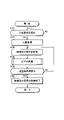
- FIG. 10 is a flowchart showing a specific example of the video conference process.
- the video conference processing of FIG. 10 is performed by a program storage unit 12 (acquisition unit 121, motion detection unit 122, video selection unit 123, video generation unit 124, audio selection unit 125, audio generation unit 126, output unit 127, etc.).
- the necessary program is read from 15 and executed.
- FIG. 10 An example is illustrated in which a Web conference is performed on each terminal device 20 of a plurality of participants connected to the video conference device 10 via a network by this video conference process.
- the video conference device 10 can perform a Web conference by receiving a preset entry request to the virtual conference room from the terminal device 20 of each participant.
- FIG. 12 is an explanatory view of the action when no face movement is detected
- FIG. 13 is an action explanatory view when the presence of face movement is detected.
- the case of the small conference room R1 in which the table 183c and oneself are displayed as a virtual conference room is illustrated, but in FIGS. 12 and 13, the table 183c and oneself are not displayed and only the other party is displayed.
- the case of the face-to-face conference room R4 (see FIG. 3) will be illustrated. Only Participant B is displayed on the display screen 252 of Participant A in FIGS. 12 and 13, and only Participant A is displayed on the display screen 252 of Participant B.
- the display of the table 183c, the whiteboard 183d, and the like can be switched during the meeting.
- the control unit 12 determines whether or not the entry request has been received from the terminal device 20 in step S110 of FIG. 10, and if it is determined that the input request has been received, the control unit 12 performs the entry process in step S120. Specifically, it accepts a user's login to the video conference system 100 and a request to enter the virtual conference room. By entering the virtual conference room provided on the server of the video conference device 10, it becomes possible to perform a two-way Web conference with another terminal device 20 that has already entered the room.
- the virtual conference room here is a conference room selected in advance from FIG. 3 by the host participant.
- the control unit 12 Upon accepting entry into the virtual conference room, the control unit 12 registers the user as a participant, stores the participant information shown in FIG. 4, starts acquiring video and audio in step S130, and starts the acquisition of video and audio in step S140. Execute the process.
- video processing the movement of a participant's face is detected, and video and audio from another participant's imaging device are selected according to the movement of the face to generate moving image data. The details of video processing will be described later.
- step S150 the control unit 12 determines whether or not the exit request has been received from the terminal device 20. While the exit request is not received, the processes of steps S130 and SS140 are repeated. When the control unit 12 determines that the exit request has been received from the terminal device 20, the control unit 12 ends the acquisition of the video and audio from the terminal device 20 for which the exit request has been made in step S160, and logs out the participant. For the other terminal device 20, the processes of steps S130 and S140 are continued. Then, when all the terminal devices 20 request to leave the room and the acquisition of the video and audio is completed, the series of video conference processing is completed.
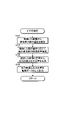
- FIG. 11 is a flowchart showing a specific example of the video processing shown in FIG.
- This video processing is an example of the communication program of the present invention.
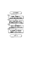
- the control unit 12 detects the movement of the participant's face from at least one of the plurality of images acquired by the acquisition unit 121.
- the acquisition unit 121 uses the image pickup device 24 to perform four images (images of faces in different directions) from all the image pickup devices 24a, 24b, 24c, and 24d from the terminal devices 20A and 20B of the participants A and B, respectively. Is obtained for each participant A and B.
- the motion detection unit 122 detects the movement of the faces of the participants A and B from at least one of the four acquired images. For example, the movement of the face is detected from the image of the face in front of the image pickup device 24c.
- the movement of the face detected by the motion detection unit 122 of the present embodiment is not the movement of the line of sight or the direction of the face, but the movement of the face in the horizontal direction (right direction or left direction) or the vertical direction (upward or downward direction). Is.
- FIG. 13 shows a case where the motion detection unit 122 detects that the face of the participant A has a movement (movement of the face to the left), and that of the participant B has a case where the face does not move.
- control unit 12 selects one video and audio from the four videos of other participants according to the movement of the face in step S144, and in step S146.
- the output video and output audio are generated from the selected video and audio, and the output video and output audio are output as moving image data in step S148.
- the movement detection unit 122 detects that there is movement of the face when the moving distance of the face is equal to or longer than a predetermined distance, and even if the face moves, the face moves when the moving distance of the face is smaller than the predetermined distance. It may be possible to detect no movement of. According to this, it is possible to prevent the image from changing even if the face moves a little. By adjusting the predetermined distance to detect the movement of the face, the image changes so that it does not change too frequently due to the subtle movement of the face, or the image changes only when the face is intentionally moved. Can be adjusted to do so.
- step S144 both the participants A and B have the image of the front of the face from the image pickup device 24c (the image of the image pickup device 24c). Participants A and B are selected by the video selection unit 123, and the left and right sounds are selected by the audio selection unit 125 from the microphone 26.
- step S146 the video generation unit 124 generates an output video from the selected video, and the audio generation unit 126 generates an output audio from the selected audio.
- step S148 the output unit 127 outputs the generated output video and output audio as image data.
- the image of the front of the face of the participant B (the image of the imaging device 24c) is displayed on the display screen 252 of the participant A, and the left and right sounds are output as they are.
- the image of the front of the face of the participant A (the image of the imaging device 24c) is displayed, and the left and right sounds are output as they are.
- step S144 If there is a leftward movement of Participant A as shown in FIG. 12 during the meeting, the leftward movement of Participant A is detected in step S144, and another participation in step S146.
- the image on the right side of the face image of the image pickup device 24a
- the sound on the right side from the microphone 26 is selected by the sound selection unit 125.
- the image generation unit 124 generates an output image on the right side of the face from the selected image.
- the voice generation unit 126 generates an output voice in which the voice from the participant B output to the terminal device 20A of the participant A is stronger on the right side than on the left side from the selected voice. At this time, as shown in FIG.
- step S148 the output unit 127 outputs the generated output video and output audio as image data.
- the image on the right side of the face of the participant B (the image of the imaging device 24a) is displayed on the display screen 252 of the participant A, and the sound on the right side is stronger than that on the left side.
- the image of the front of the face of the participant A (the image of the imaging device 24c) is displayed, and the left and right sounds are output as they are.
- the image on the left side of the face of the participant B (the image of the imaging device 24b) is displayed on the display screen 252 of the participant A, and the image on the right side is displayed. A stronger sound than the left is output.
- the image of the front of the face of the participant A (the image of the imaging device 24c) is displayed shifted to the right, and the right side outputs a stronger sound than the left side. Will be done.
- participant B by switching the image of another participant B to the image of the image pickup device on which the participant A moves according to the movement of the face of the participant A, an actual conference is held. Participant B's profile can be seen as if he were moving in that direction in the room. In this way, the appearance of other participants can be changed according to the movement of one's face, so that the person can feel as if he / she is there. Further, depending on the movement of the face and the angle of the image pickup device 24, the line of sight can be adjusted, which facilitates conversation.
- FIG. 14 is a diagram showing a schematic configuration of the video conference system 100 of the second embodiment, in the case of four participants.
- the terminal device 20A of the participant A, the terminal device 20B of the participant B, the terminal device 20C of the participant C, and the terminal device 20D of the participant D are installed on the server constituting the video conference device 10. Is connected by network N. Since the terminal devices 20A, 20B, 20C, and 20D all have the same configuration as that of FIG. 6, detailed description thereof will be omitted.
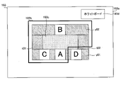
- FIG. 15 is a diagram showing a specific example of the virtual conference room display information 183 of the second embodiment, and is an example when the virtual conference room of the middle conference room R2 of FIG. 3 is used. Images of each participant can be fitted in the A to D frames of FIG. In the configuration of FIG. 14, the image of the participant A is fitted in the A frame arranged in the row y01, the image of the participant B is fitted in the B frame arranged in the row 02, and the C frame arranged in the column t01. The image of participant C is fitted in the frame, and the image of participant D is fitted in the D frame arranged in the parallel column t02.
- FIG. 14 shows a case where the display range 183b of FIG. 15 is three-dimensionally displayed. In FIG. 5, the display range 183b is the range including the columns in which the participants A to D are arranged and the table 183c. In FIG. 15, as in FIG. 5, the whiteboard 183d is not displayed because it is not included in the display range 183b.
- FIG. 16 is a diagram showing the relationship between the appearance of the participant A on the display screen 252 and the imaging device of another participant.
- FIG. 17 is a diagram showing the relationship between the appearance of the participant B on the display screen 252 and the imaging device of another participant.
- each participant A to D when oneself is placed in front of the table 183c in the virtual conference room of FIG. 15, other participants are placed at the same positions as those seen on the back side, right side, and left side. ..
- FIG. 16 on the display screen 252 of Participant A, oneself (Participant A) is in front of the table 183c, Participant B is on the back side, Participant C is on the left side, and Participant D is on the left side. It is displayed on the right side respectively.
- the participant B self is on the front side
- the participant A is on the back side
- the participant D is on the left side
- the participant C is on the table 183c.
- the face orientation of each participant A to D is the same as the face orientation seen from the back, right side, and left side when oneself is placed in front of the table 183c in the virtual conference room shown in FIG. Display the image of the face orientation of the participant.
- the image of the front of the face from the image pickup device 24c is displayed for the participant A (self) and the participant B, and the image pickup device 24a for the participant C.
- the image on the right side of the face from the image is displayed, and the image on the left side of the face from the image pickup device 24b is displayed for the participant D.
- FIG. 16 the image of the front of the face from the image pickup device 24c is displayed for the participant A (self) and the participant B, and the image pickup device 24a for the participant C.
- the image on the right side of the face from the image is displayed, and the image on the left side of the face from the image pickup device 24b is displayed for the participant D.
- the image of the front of the face from the image pickup device 24c is displayed for the participant B (self) and the participant A, whereas the participants.
- For C the image on the left side of the face from the image pickup device 24b is displayed, and for participant D, the image on the right side of the face from the image pickup device 24a is displayed.
- the positions of participants C and D and the orientation of their faces are reversed in FIGS. 16 and 17.
- the images of the image pickup apparatus are switched so as to match the positions of the other participants A to D and the face orientation when it is assumed that the user is in front of the virtual conference room. It is displayed on the display screen 252 of the participants A to D.
- the display screens 252 of the participants A to D can be displayed in the same position and orientation as in the case of the actual conference room. Therefore, the Web conference can be held as if you were in the conference room.
- FIG. 18 is a flowchart showing a specific example of the video processing of the second embodiment, and is a modification of the video processing shown in FIG.
- the display range 183b can be changed according to the movement of the participant's face (movement of the face).
- FIG. 19 is an operation explanatory diagram when the movement of the face is detected in the second embodiment
- FIG. 20 is a diagram showing a specific example of the virtual conference room display information 183 at that time.
- step S242 the control unit 12 detects the movement of the face of at least one participant from the video acquired by the acquisition unit 121.
- the motion detection unit 122 detects the movement of the participant's face from at least one image (for example, the image of the front face) of the four images acquired by the acquisition unit 121 for each participant. Since step S242 is the same as step S142 in FIG. 11, detailed description thereof will be omitted.
- the control unit 12 selects the video and audio of another participant according to the movement of the face in step S244.
- the display range 183b is selected by the image selection unit 123 according to the movement of the face for the image. For example, when the participant A moves his / her face to the left as shown in FIG. 19, the image selection unit 123 selects a display range 183b'shifted in the same direction (left side) as the movement of the face as shown in FIG. .. If Participant A moves his face to the right, a display range shifted to the right (not shown) is selected. If Participant A moves his face up, the display range shifted up (not shown) is selected, and if Participant A moves his face down, the display range shifted down (not shown) is selected. Be selected. As for the voice, the voices of the participants B and C included in the display range 183b'are selected by the voice selection unit 125, and the voices of the participants D not included in the display range 183b' are not selected by the voice selection unit 125.
- the control unit 12 generates output video and output audio from video and audio in the selected display range 183b in step S246, and outputs the output video and output audio as moving image data in step S248.
- the display range 183b'of FIG. 20 is reflected and displayed on the display screen 252 according to the movement of the face of the participant A.
- the display range 183b before detecting the movement of the face is shown by a dotted line.
- the participant A can hide the specific participant D on the display screen 252 by moving his / her face.
- the voice of the participant D not included in the display range 183b' is not selected by the voice selection unit 125, it cannot be heard by the terminal device 20 of the participant A.
- the display range 183b can be changed according to the movement of the face with respect to the display screen 252. This makes it possible to talk only with the participants who want to talk by moving their faces.
- FIGS. 19 and 20 illustrate a case where the display range 183b is shifted to the left by moving the face to the left with respect to the display screen 252, but the present invention is not limited to this, and the display screen 252 is left and right (horizontal direction).
- the display range 183b can also be shifted left and right or up and down.
- the display range 183b can be shifted to the right by moving the face to the right.
- the display range 183b can be moved upward by moving the face further upward.
- the display range 183b can also be shifted downward by moving the face downward.
- the amount of shift of the display range 183b can be changed according to the distance the face moves. For example, the greater the movement of the face, the greater the amount of shift in the display range 183b.
- the display range 183b is regarded as the field of view of the participants, the participants can see according to the movement of their faces, so that they can get a sense of reality as if they were in an actual conference room.
- a video is generated in which the position where the participant is displayed is specified according to the position of the participant in the virtual conference room, so that the position of the other participant is as if it were an actual conference. You can hold video conferences and conversations as if you were in a room.
- the image of the participant is selected according to the position of the participant in the virtual conference room, for example, the participant next to him / her can display the image of the profile. As a result, video conferences and conversations can be conducted with the appearance of other participants as if they were in an actual conference room.
- the display range 183b of the virtual conference room is selected according to the movement of the faces of the participants, and the participants included in the display range 183b among the plurality of participants are displayed on the terminal device 20.
- Video can be generated. According to this, by moving one's face, the desired range of the virtual conference room can be displayed. For example, if you want to see only the participants on the right side of the table 183c, you can move your face to the right so that only the participants on the right side can see. It is also possible to display only the participant and have a conversation only with the participant by moving the face to the participant who is talking, just as if he / she goes near the participant and has a conversation in the actual conference room. In this way, you can get a sense of realism as if you were having a conversation in an actual conference room.
- a third embodiment of the present invention will be described.
- the motion detection unit 122 of the first embodiment and the second embodiment a case where "movement of the face” (movement in the horizontal direction or the vertical direction with respect to the display screen 252) is detected as the "movement of the face” has been illustrated. Not limited.
- the motion detection unit 122 of the third embodiment illustrates a case where the “face orientation” is detected as the “face movement” and the appearance of the participants on the virtual conference room is changed according to the orientation of the face. Since the configuration of the video conference device 10 of the third embodiment is the same as that of the first embodiment, detailed description thereof will be omitted.
- the video conference system 100 of the third embodiment will be described by taking the case of four participants (FIG. 14) as an example as in the second embodiment.
- FIG. 21 is a flowchart showing a specific example of the video processing of the third embodiment, and is another modification of the video processing shown in FIG.
- the control unit 12 detects the orientation of the participant's face from the acquired video.
- the control unit 12 selects the video and audio of another participant according to the face orientation in step S344.
- the control unit 12 generates output video and output audio from video and audio in the display range 183b selected in step S346, and outputs the output video and output audio as moving image data in step S348.
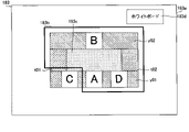
- FIG. 22 is a diagram showing a specific example of the virtual conference room display information 183 according to the third embodiment.
- FIG. 23 is a diagram showing how the virtual conference room display information 183 in FIG. 22 is viewed by the participant A.
- FIG. 24 is a diagram showing virtual conference room display information 183 when the face direction moves from the front to the left
- FIG. 25 is a diagram showing how participants A see the virtual conference room display information 183 of FIG. 24.
- FIG. 26 is a diagram showing virtual conference room display information 183 when the face direction moves from the front to the right
- FIG. 27 is a diagram showing how participants A see the virtual conference room display information 183 of FIG. 26. Is.
- Participant C and Participant D are in the same row as Participant A (row y01), Participant C is placed on the left side of Participant A, and Participant D is placed on the right side of Participant A.
- the participants in the same row can be displayed only when the face is changed. That is, as shown in FIG. 22, when the face of the participant A is facing the front, the display range of FIG. 22 is 183b, and the participants C and D in the same row are not displayed and no sound is output.
- FIG. 25 when the motion detection unit 122 detects the leftward orientation of the participant A, only the left participant C in the same row is displayed by the virtual conference room display information 183 in FIG. 24, and the participant C is displayed. Audio is output.
- FIG. 27 when the motion detection unit 122 detects the direction of the face of the participant A to the right, only the participant D on the right side in the same row is displayed by the display range 183b in FIG. Audio is output.
- the participant A when the participant A is facing the front, if the movement of the face is not detected, the participants C and D are not displayed and the conversation with only the participant B is possible. ..
- Participant A when Participant A turns to the left, he / she can talk with Participant C, and when Participant A turns to the right, he / she can talk to Participant D.
- Participant A when Participant A turns to the left, he / she can talk with Participant C, and when Participant A turns to the right, he / she can talk to Participant D.
- the motion detection unit 122 has the participant's face facing forward, right, or left from at least one of the four images acquired by the acquisition unit 121. It can detect whether it is a face or not.
- the image selection unit 123 selects the display range 183b of the virtual conference room located on the right side and the left side, which does not include the image of the participant, and the detected face orientation is rightward.
- the display range 183b of the virtual conference room including the image of the participant located on the right side is selected, and if the detected face orientation is to the left, the virtual conference room including the image of the participant located on the left side is selected. Display range 183b can be selected.
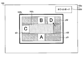
- FIG. 28 is a diagram showing a specific example of the virtual conference room display information 183 according to the first modification, and is a case where the participant D in the column t02 of FIG. 15 is moved to the row y02 in position (seat).
- FIG. 29 is a diagram showing how Participant D looks from Participant A after moving his / her seat.
- FIG. 30 is a diagram showing the appearance of the participant D from the participant D before the seat movement
- FIG. 31 is a diagram showing the appearance of the participant D from the participant D after the seat movement.
- the movement of the seat of the participant D can be seen from the right side of the table 183c to the side of the participant C on the back side when viewed from the participant A, so that the movement can be seen at a glance.
- Participant C was seen behind the table 183c as shown in FIG. 30 before the seat was moved, whereas by moving the seat, the back side of the table 183c was seen as shown in FIG. Participant A will be visible in.
- the appearance similar to that of the actual conference room can be realized in the video conference, so that the sense of presence can be enhanced. ..
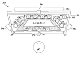
- FIG. 32 is a diagram showing a specific example of the virtual conference room display information 183 according to the second modification, and illustrates the display range (in the case of 16 participants) of the large conference room R3 of FIG.
- FIG. 33 is a diagram showing how the virtual conference room display information 183 of FIG. 32 is viewed from the participant A1.
- FIG. 32 is a diagram showing a specific example of the virtual conference room display information 183 according to the second modification, and illustrates the display range (in the case of 16 participants) of the large conference room R3 of FIG.
- FIG. 33 is a diagram showing how the virtual conference room display information 183 of FIG. 32 is viewed from the participant A1.
- the images of the right faces of the four participants are lined up, and on the right side of the table 183c, the left faces of the four participants (D1, D2, D3, D4). Images can be seen side by side. Further, since the image of the participant A4 as a presenter can be seen in the upper right of the display screen 252, it can be seen at a glance that the participant A4 is giving a presentation. As shown in FIGS. 32 and 33, the whiteboard 183d may be displayed on the table 183c. In this case, the orientation of the whiteboard 183d can be adjusted so that it looks the same to any participant.
- the presenter row p01 (example of the row of the speaking area) is provided separately from the other rows y01 and y02 and the columns t01 and t02.
- the participant A4 is the presenter, and the participant A4 illustrates the case where the seat is moved from the row y01 to the presenter row p01.
- the row of presenters p01 (row of the speaking area) is for one person, but there may be two or more people. This is because there are cases where two or more people give a presentation.
- a fourth embodiment of the present invention will be described.
- the "faces" of the other participants are obtained according to the movements of the faces of the participants.
- the case where "the image of” can be changed is illustrated.
- the fourth embodiment by using an omnidirectional (360 degree) camera as the image pickup device 24 to acquire omnidirectional images in different directions, the other participant's "surrounding image” is obtained according to the movement of the participant's face. Is also illustrated.
- the "surrounding image” here includes not only the background image of the participants but also the images such as the front image, the right image, and the left image.
- the appearance of such surrounding images can be changed according to the movement of the participants' faces, so that a more realistic experience becomes possible.
- the participants who are watching the video simply move their faces in the desired direction to see the prototype. You can switch the direction you want to see the surrounding image including the image of, and you can also move the surrounding image. According to this, it can be used not only in product development meetings, but also in various situations such as when you want to talk remotely with the site director while watching the image of the building at the construction site, or when you want to talk with the clerk while watching the product in the showroom. .. What's more, the participants who are watching the video can change the appearance of the surrounding video, including the video of the building and the video of the product, just by moving their faces in the direction they want to see, so it feels as if they are there. You can communicate smoothly with.
- FIG. 34 is a diagram showing a schematic configuration of the communication system 101 of the fourth embodiment.
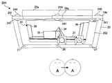
- FIG. 35 is a schematic view of the terminal device 20B of FIG. 34 as viewed from the front, and is a diagram showing a specific example of the installation position of the image pickup device.
- the communication system 101 of FIG. 34 is configured by connecting the terminal device 20A of the participant A and the terminal device 20B of the participant B to the server constituting the communication device 11 by a network N. Since the terminal devices 20A and 20B have almost the same configuration as that of FIG. 6, elements having the same function will be described with the same reference numerals.
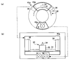
- FIG. 34 is an example in which not only the images of the faces of the participants A and B in front of the image pickup device 24 but also the images of the structure 30 behind the image pickup device 24 are displayed on the terminal devices 20A and 20B. Since the image pickup device 24 of the first to third embodiments is an inner camera facing the participant who is looking at the terminal device 20, it is not possible to take a picture of what is behind the image pickup device 24. Therefore, in FIG. 34, by applying the omnidirectional camera to the image pickup device 24, not only the image of the participant's face but also the surrounding image including the image of the structure T can be seen on the terminal devices 20A and 20B. It was done. Hereinafter, such an image pickup apparatus 24 will be specifically described.
- the terminal devices 20A and 20B of FIG. 34 are provided with image pickup devices 24 (imaging devices 24e, 24f, 24g) composed of omnidirectional cameras, respectively.
- the image pickup devices 24e, 24f, and 24g capture an omnidirectional image including an image of the face of the participant in different directions and an image of the surroundings in different directions as shown in FIG. 41 and the like described later.
- the "surrounding image” here is a horizontal 360-degree omnidirectional image including the image of the participant's face, and includes, for example, the image of the participant's background, the front image, the right image, the left image, and the like. ..
- the image pickup device 24 does not necessarily have to be installed on the display device 25. It may be installed in a suitable place. Further, the image pickup device 24 does not necessarily have to be electrically connected to the terminal devices 20A and 20B.
- the image pickup device 24 may have any configuration as long as the image data including the image of the face in different directions and the image of the surroundings in different directions is transmitted to the communication device 11 via the network N.
- the image pickup device 24 does not necessarily have to be a camera capable of capturing an image in all directions (360 degrees).
- a wide-angle camera capable of capturing an image of a predetermined angle or more may be used.
- the image pickup device 24 may have a configuration in which two wide-angle cameras are combined with an inner camera and an outer camera so as to be able to capture an omnidirectional image, or an inner camera such as a smartphone and an outer camera may be used as the image pickup device 24.
- an image pickup device 24 capable of capturing an omnidirectional image with the outer camera 246 and the inner camera 247 is illustrated.
- the image of the participant's face and the background image can be acquired from the inner camera 247, and the image in front of the participant can be acquired from the outer camera 246.
- the image pickup apparatus 24 may be a camera including one fisheye lens or a convex mirror.
- the orientation of the image pickup apparatus 24 is not limited to that shown in the figure.
- the lens may be set upward or downward.
- the lens may be arranged so as to face upward.
- the number of image pickup devices 24 in FIG. 34 is not limited to three.
- FIG. 35 is a schematic view of the terminal device of FIG. 34 as viewed from the front, and is a diagram showing a specific example of the installation position of the image pickup device.
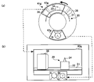
- FIG. 36 is a view of the terminal device 20B of FIG. 34 as viewed from above, and is a diagram showing specific examples of ambient images from the respective image pickup devices 24e, 24f, and 24g. Since the terminal device 20A has the same configuration, the terminal device 20B will be described here as a representative.
- the image pickup devices 24e, 24f, and 24g are arranged side by side on the upper part of the display device 25.
- the image pickup device 24g is a central image pickup device (third image pickup device) arranged in the upper center of the display device 25.
- the image pickup device 24g can capture 41g of a horizontal 360-degree omnidirectional image as shown in FIG. 41 (a) described later.
- the omnidirectional image 41g includes an image of the front of the face of the participant B as shown in FIG. 8 and an image of the front of the structure 30 as shown in FIG. 36 40g.
- the image pickup device 24e is a right-hand image pickup device (first image pickup device) arranged above the display device 25 at a distance to the right of the image pickup device 24 g.
- the image pickup apparatus 24e can capture a horizontal 360-degree omnidirectional image 41e as shown in FIG. 45 (a) described later.
- the omnidirectional image 41e includes an image on the right side of the face of the participant B as shown in FIG. 8 and an image 40e from the front right side of the structure 30 as shown in FIG.
- the image pickup device 24f is a left side image pickup device (second image pickup device) arranged above the display device 25 at a distance to the left of the image pickup device 24 g.
- the image pickup apparatus 24f can image a horizontal 360-degree omnidirectional image 41f as shown in FIG. 43A, which will be described later.
- the omnidirectional image 41f includes an image on the left side of the face of the participant B as shown in FIG. 8 and an image 40f from the front left side of the structure 30 as shown in FIG.
- the structure 30 is formed by arranging a plurality of objects 32, 34, 36, 38 on the substrate 31, for example.
- the object 32 is a rectangular parallelepiped
- the object 34 is a quadrangular pyramid
- the object 36 is a hexagonal prism
- the object 38 is a quadrangular prism.
- the object 32 and the object 34 are arranged substantially in the center of the front surface of the substrate 31, and the object 34 is arranged behind the object 32.
- the object 36 is arranged on the front right side (facing right side)
- the object 38 is arranged on the front left side (facing left side).
- the object 34 is hidden by the object 32 and only the triangular portion at the tip can be seen. With this, the shape of the object 34 is also unknown. Looking only at the front image 40g, it seems that the object 34 has a triangular plate shape and is arranged on the object 32.
- the object 34 is separated from the object 32 and is arranged behind, and that the object 34 is not a triangular plate shape but a pyramid.
- the front right side image and the front left side image can be acquired from the omnidirectional image including the image in the direction different from the front image, it may not be possible to understand from the front image alone. You will understand.
- the images 40e, 40f, and 40g in FIG. 34 are developed images obtained by cutting out images in the display range including the structure 30 from the omnidirectional images of the image pickup devices 24e, 24f, and 24g, respectively.
- the fourth embodiment has a major feature in that the display range cut out from the omnidirectional video can be changed according to the "face movement" of the participant.
- FIG. 37 is a block diagram of the communication system 101 of the fourth embodiment, and shows a specific configuration example of the communication device 11 and the terminal device 20. Since the configuration of the terminal device 20 of FIG. 37 is almost the same as that of FIG. 2, detailed description thereof will be omitted.
- the configuration of the communication device 11 of FIG. 37 is the same as that of the video conference device 10 of FIG. 2, and the same reference numerals are given to the configuration, and detailed description thereof will be omitted.
- the communication device 11 of FIG. 37 includes a video selection unit 123A, a video generation unit 124A, a sound selection unit 125A, and a sound generation unit 126A.
- the image selection unit 123A includes a face image selection unit 123a and a surrounding image selection unit 123b.
- the face image selection unit 123a selects the "face image” of another participant according to the "face movement" of the participant detected by the motion detection unit 122.
- the surrounding image selection unit 123b selects the "surrounding image” according to the "face movement" of the participant detected by the motion detection unit 122.
- the image generation unit 124A includes a face image generation unit 124a and a surrounding image generation unit 124b.
- the face image generation unit 124a generates an image of a participant to be displayed on the terminal device 20 from the image of the face selected by the face image selection unit 123a.
- the ambient image generation unit 124b generates an ambient image to be displayed on the terminal device 20 from the ambient image selected by the ambient image selection unit 123b. In this way, the image selection unit 123A and the image generation unit 124A can not only select and generate the "face image” but also select and generate the "surrounding image".
- the sound selection unit 125A includes a voice selection unit 125a and an ambient sound selection unit 125b.
- the voice selection unit 125a selects the voices of other participants according to the "face movement" of the participant detected by the motion detection unit 122.
- the ambient sound generation unit 126b selects ambient sounds according to the "face movement" of the participant detected by the motion detection unit 122.
- the sound generation unit 126A includes a voice generation unit 126a and an ambient sound generation unit 126b.
- the voice generation unit 126a generates the voice output by the terminal device 20 from the voice selected by the voice selection unit 125a.
- the ambient sound generation unit 126b generates the ambient sound output by the terminal device 20 from the ambient sound selected by the ambient sound selection unit 125b.
- the sound selection unit 125A and the sound generation unit 126A can not only select and generate "voice” but also select and generate "ambient sound”.
- the acquisition unit 121 may acquire the sound and the surrounding sound from separate microphones 26, or may acquire the sound and the surrounding sound separately from the input sound of one microphone 26. good.
- the ambient sound selection unit 125b and the ambient sound generation unit 126b do not necessarily have to be provided. In that case, only the sound may be output from the terminal device 20, or the sound with the surrounding sounds may be output from the terminal device 20.
- the data table of FIG. 38 is virtual conference room configuration information 181 for displaying the video of the participant and the surrounding video on the terminal device 20 using the virtual conference room, and corresponds to FIG.
- the virtual conference room configuration information 181 of FIG. 38 is different from that of FIG. 3 in that the items of the face image and the surrounding image are inserted instead of the table and the board.
- the items in FIG. 38 are not limited to those shown in the drawings, and items for tables and boards may be included. According to FIG. 38, for example, in the small conference room R1, since there is a face image of the participant and a surrounding image, a display range including the face image and the surrounding image is set.
- the data table of FIG. 39 is participant information 182 and corresponds to FIG.
- the video data received in this embodiment is three omnidirectional videos from the imaging devices 24e, 24f, and 24g.
- the virtual conference room display information 183 in FIG. 40 is the display information of the virtual conference room in which each participant enters.
- the virtual conference room display information 183 of FIG. 40 in addition to the row in which each participant is arranged and the position of each participant (the position of the face image frame in which the image of the participant is fitted), the surrounding image frame in which the surrounding image is fitted.
- the position of r01, the display range 183b of the virtual conference room, and the like are included.
- the virtual conference room display information 183 is provided for each type of the virtual conference room of the virtual conference room configuration information 181 of FIG. 38. Which virtual conference room to use can be set in advance by the host participant.
- FIG. 40 illustrates a case where two participants A and B use the virtual conference room of the small conference room R1 of FIG. 38.
- the outer frame 183a shows the entire virtual conference room.
- the thick frame inside shows the display range 183b.
- the small conference room R1 in FIG. 38 has a capacity of two people, a face image, a surrounding image, and one row.
- the surrounding image frame r01 is arranged on almost the entire surface, and the row y01 including the face image frame yA of the participant A and the face image frame yB of the participant B is arranged below the surrounding image frame r01.
- the configuration of the virtual conference room display information 183 is not limited to that shown in the figure.
- the communication device 11 of the fourth embodiment also performs the same video conference processing as in FIG.
- the video processing of step S140 in FIG. 10 will be described with reference to FIG.
- FIG. 11 is a flowchart showing a specific example of the video processing shown in FIG.
- This video processing is an example of the communication program of the present invention.
- the same processing is performed from step S142 to step S148.
- the video processing of the fourth embodiment is different from that of the first embodiment only by selecting the video and audio of the faces of other participants according to the facial movements of the participants detected in steps S144 and S146. Instead, the surrounding video and ambient sound are also selected to generate the output video and output audio.
- FIGS. 41 to 46 are diagrams for explaining how the image of the participant B and the image of the structure 30 change according to the movement of the face of the participant A.
- 41 and 42 show the case where the face movement of the participant A is detected
- FIGS. 43 and 44 show the case where the participant A detects the movement of the face to the left
- FIGS. 45 and 46 show. Is the case where the participant A detects the movement of the face to the right.
- FIG. 42 is a diagram showing a display image that the participant A can see from the front without moving his / her face.
- FIG. 44 is a diagram showing a display image in which the participant A appears to move his / her face to the left.
- FIG. 46 is a diagram showing a display image in which the participant A appears to move his / her face to the right.
- the control unit 12 detects the movement of the participant's face from at least one of the plurality of images acquired by the acquisition unit 121.
- the acquisition unit 121 uses the image pickup device 24 to perform three omnidirectional images (images of the surroundings in different directions) from all the image pickup devices 24e, 24f, and 24g from the terminal devices 20A and 20B of the participants A and B, respectively. Is obtained for each participant A and B.
- an omnidirectional image including the front image of the structure 30 and the front face image of the participant B as shown in FIG. 41A is acquired from the image pickup device 24g of the participant B.
- an omnidirectional image including the front left side image of the structure 30 and the left face image of the participant B as shown in FIG. 43A is acquired from the image pickup device 24e of the participant B.
- an omnidirectional image including the front right side image of the structure 30 and the right face image of the participant B as shown in FIG. 45A is acquired.
- the omnidirectional images including the facial image and the surrounding image are also acquired from the image pickup devices 24e, 24f, and 24g of the participant A.
- the face image of the participant is recognized from at least one of the three acquired omnidirectional images, and the motion detection unit 122 detects the movement of the faces of the participants A and B from the face image. Detect.
- the movement of the face is detected from the image of the face of the participant B included in the omnidirectional image of FIG. 41 (a). In this case, it is not always necessary to use the omnidirectional image for detecting the movement of the face, and the image obtained by developing the image of the participant's face may be used.
- the movement of the face detected by the motion detection unit 122 of the present embodiment is the movement of the face to the right or left, and the change of the direction of the face such as left or right.
- the control unit 12 selects one video and audio from the three omnidirectional videos of other participants according to the movement of the face in step S144, and steps S146.
- the output video and output audio are generated from the omnidirectional video and audio selected in step S148, and the output video and output audio are output as moving image data in step S148.
- the image selection unit 123A collects all of the image pickup device 24g of the participant B shown in FIG. 41 (a). Select 41 g of directional image. Specifically, for the face image, the face image selection unit 123a selects the display range 42g of the face image of the participant B from the omnidirectional image 41g shown in FIG. 41 (a), and the face image generation unit 124a displays the display range. 42 g is cut out and a facial image of participant B is developed as shown in FIG. 41 (b).
- the surrounding image selection unit 123b selects a display range 43g of the surrounding image including the image of the structure 30 from the omnidirectional image 41g shown in FIG. 41 (a), and the surrounding image generating unit 124b selects the display range.
- 43 g is cut out and the surrounding image including the image of the structure 30 is developed into a rectangle as shown in FIG. 41 (b).
- the face image of the participant A is also cut out from the omnidirectional image 41 g from the image pickup device 24 g of the participant A and developed into a rectangle.
- the image generation unit 124A includes the face image of the participant A, the face image of the participant B, and the surrounding image including the image of the structure 30 developed as described above based on the virtual conference room display information 183 of FIG. 40. Generate output video from. Specifically, the image generation unit 124A fits the surrounding image including the image of the structure 30 into the surrounding image frame r01 of FIG. 40, and fits the face image of the participant A into the face image frame of the participant A in the row y01. The face image of participant B is fitted into the face image frame of participant B in the row y01. In this way, the image generation unit 124A generates the output image of FIG. 41 (b) from the omnidirectional image 41 g of FIG. 41 (a).
- the left and right voices and ambient sounds were selected from the microphone 26 by the voice selection unit 125a and the ambient sound selection unit 125b, and the voice generation unit 126a and the ambient sound generation unit 126b were selected.
- the output unit 127 outputs the output video and output audio of FIG. 41 (b) as image data.
- the image of the front of the face of the participant B and the image of the front of the structure 30 are displayed on the display screen 252 of the participant A, and the left and right sounds are output as they are.
- a similar image is displayed on the display screen 252 of the participant B.
- the fourth embodiment not only the image of the participant's face but also the image of the surroundings thereof can be displayed. As a result, the participants can have a conversation while watching the surrounding images.
- the object 34 is hidden behind the object 32 and cannot be seen. Therefore, when the participant A moves his / her face to the left as shown in FIG. 44, the movement of the face is detected by the motion detection unit 122, and the participant A participates from the omnidirectional image 41f of FIG. 43 (a) by the same processing as described above.
- the display range 43f of the face image and the surrounding image of the person B is selected and expanded into a rectangle, and the output image and the output sound of FIG. 43B are generated and output as image data. Then, as shown in FIG. 44, the image on the front left side of the structure 30 is displayed on the display screen 252 of the participant A.
- the object 34 which is hidden behind the object 32 and cannot be seen in the front image, can be seen. That is, if the face is moved to the left, the image of the structure 30 can be seen from the front left side, so that the experience as if you were there is possible.
- the display position of the participant A may be moved to the left as shown in FIG. 43 (b) in conjunction with the movement of the face of the participant A to the left.
- the display position of the participant A may be moved to the left as shown in FIG. 43 (b) in conjunction with the movement of the face of the participant A to the left.
- FIG. 44 it is possible to make an image in which the participant A is looking at the structure 30 from the front left side.
- Participant B is an image on the left side of the face, so that it looks as if he / she is talking toward Participant A.
- the participant A moves his / her face to the right as shown in FIG. 46
- the movement of the face is detected by the motion detection unit 122, and the omnidirectional image of FIG. 45 (a) is processed in the same manner as described above.
- the display range 43e of the face image and the surrounding image of the participant B is selected from 41e and expanded into a rectangle, and the output image and the output sound of FIG. 45B are generated and output as image data.
- the image on the front right side of the structure 30 is displayed on the display screen 252 of the participant A.
- the object 34 which is hidden behind the object 32 and cannot be seen in the front image, can be seen. That is, if the face is moved to the right, the image of the structure 30 can be seen from the front right side, so that the experience as if you were there is possible.
- the display position of the participant A may be arranged to the right as shown in FIG. 45 (b) in conjunction with the movement of the face of the participant A to the right.
- the display position of the participant A may be arranged to the right as shown in FIG. 45 (b) in conjunction with the movement of the face of the participant A to the right.
- FIG. 46 it is possible to make an image in which the participant A is looking at the structure 30 from the front right side.
- Participant B is an image on the right side of the face, so that it looks as if he / she is talking toward Participant A.
- the display screen 252 of the participant A displays an image in which the entire structure 30 is moved to the left.
- the entire object 38 which is only partially visible in the front image, can be seen. That is, when the face is turned to the left, the image on the left side of the structure 30 can be seen, so that the experience as if you are there is possible.
- the display screen 252 of the participant A displays an image in which the entire structure 30 is moved to the right.
- the entire object 36 which is only partially visible in the front image, can be seen. That is, when the face is turned to the right, the image on the right side of the structure 30 can be seen, so that the experience can be as if you were there.
- the image (including face image and ambient image) and sound (ambient sound is stored in the storage unit) from the image pickup device 24 acquired by the acquisition unit 121.
- the image from the imaging device 24 acquired from the acquisition unit 121 can be stored in the storage unit 14.
- the image is not limited to the case where the image is acquired in real time, and the image stored in the storage unit 14 is acquired. According to this, for example, a video conference with the same face image and surrounding image as on the day is performed by using the video and audio stored in the storage unit 14 by the participant who cannot attend the video conference on the day. You can experience it. In this case as well, you can change the face image and surrounding images according to the movement of the participant's face, so you can experience as if you were there at the time you want to see. It will be possible.
- the motion detection unit 122 detects the movement of the face in the left-right direction or the up-down direction as the movement of the face of the participant.
- the movement of the face in the front-back direction may also be detected.
- the movement of the face in the front-rear direction may be detected based on the change in the position of the vector of the face and the distance between the image pickup device 24 and the image pickup device 24. According to this, for example, when a participant approaches the display screen 25 of the terminal device 20, the motion detection unit 122 detects the movement of the face in the forward direction. It will also be possible to magnify the image of the face and the image of the surroundings.
- the image when an object appearing in the surrounding image has small and unreadable characters, if the face is brought close to the display screen 25, the image is enlarged and the characters appear large and can be read. On the contrary, if the face is moved away from the display screen 25, the image on the display screen 25 may be reduced. For example, when the image is large and only a part of the object can be seen, if the face is moved away from the display screen 25, the image is reduced and the entire object can be seen. As a result, you can experience the realism as if you were looking at the real thing.
- the image may include not only the face but also the upper body.
- the face portion may be recognized from the image to detect the movement of the face. For example, using a trained model trained by machine learning with AI (artificial intelligence) or an existing trained model, recognition of a face part and movement of the face are detected from an image.
- AI artificial intelligence
- the present invention is not limited to this.
- it can be applied to various communication devices such as a web conferencing device, a video conferencing device, a video telephone device, an online conferencing device, a video calling device, and a video calling device.
- the use of the present invention is not limited to conferences, but is used in various situations such as conversations and dialogues between exhibition venues, nursing care facilities, hospital facilities, parents' homes and homes, nursing care facilities, hospitals, etc. It can be used for communication.
- Video conferencing system (communication system), 10 ... Video conferencing device (communication device), 11 ... Communication unit, 12 ... Control unit, 121 ... Acquisition unit, 122 ... Detection unit, 123 (123A) ... Video selection unit, 123a ... Face image selection unit, 123b ... Surrounding image selection unit, 124 (124A) ... Image generation unit, 124a ... Face image generation fixed unit, 124b ... Surrounding image generation unit, 125A ... Sound selection unit, 125 (125a) ... Audio selection Unit, 125b ... Ambient sound selection unit, 126A ... Sound generation unit, 126 (126a) ... Voice generation unit, 126b ... Ambient sound generation unit, 127 ...
- First image pickup device (right side image pickup device), 24b, 24f ... Second image pickup device (left side image pickup device), 24c, 24 g ... Third image pickup device (center image pickup device) , 24d ... Fourth imaging device (lower imaging device), 242a, 242b, 242c, 242d ... Support, 244a, 244b, 244c, 244d ... Rotating shaft, 246 ... Outer camera, 247 ... Inner camera, 25 ... Display device , 252 ... Display screen, 26 ... Microphone, 27 ... Speaker, 28 ... Input device, 40e, 40f, 40g ... Video, 41e, 41f, 41g ... Omnidirectional video, 42e, 42f, 42g ...
- Face image display range, 43e , 43f, 43g Surrounding image display range, t01 ... Column, t02 ... Column, y01 ... Row, y02 ... Row, AD ... Participants, N ... Network, R1 ... Small meeting room, R2 ... Medium meeting room, R3 ... Large conference room, R4 ... Face-to-face conference room.
Landscapes
- Engineering & Computer Science (AREA)
- Signal Processing (AREA)
- Multimedia (AREA)
- Theoretical Computer Science (AREA)
- General Engineering & Computer Science (AREA)
- Physics & Mathematics (AREA)
- Human Computer Interaction (AREA)
- General Physics & Mathematics (AREA)
- Computer Networks & Wireless Communication (AREA)
- Two-Way Televisions, Distribution Of Moving Picture Or The Like (AREA)
- Position Input By Displaying (AREA)
- User Interface Of Digital Computer (AREA)
- Telephonic Communication Services (AREA)
Priority Applications (1)
| Application Number | Priority Date | Filing Date | Title |
|---|---|---|---|
| JP2022528302A JP7306765B2 (ja) | 2021-01-18 | 2022-01-18 | コミュニケーション装置及びコミュニケーションプログラム並びに記憶媒体 |
Applications Claiming Priority (2)
| Application Number | Priority Date | Filing Date | Title |
|---|---|---|---|
| JP2021005996 | 2021-01-18 | ||
| JP2021-005996 | 2021-01-18 |
Publications (1)
| Publication Number | Publication Date |
|---|---|
| WO2022154128A1 true WO2022154128A1 (ja) | 2022-07-21 |
Family
ID=82448208
Family Applications (1)
| Application Number | Title | Priority Date | Filing Date |
|---|---|---|---|
| PCT/JP2022/001637 Ceased WO2022154128A1 (ja) | 2021-01-18 | 2022-01-18 | コミュニケーション装置及びコミュニケーションプログラム並びに記憶媒体 |
Country Status (2)
| Country | Link |
|---|---|
| JP (1) | JP7306765B2 (cg-RX-API-DMAC7.html) |
| WO (1) | WO2022154128A1 (cg-RX-API-DMAC7.html) |
Cited By (1)
| Publication number | Priority date | Publication date | Assignee | Title |
|---|---|---|---|---|
| JP2024047795A (ja) * | 2022-09-27 | 2024-04-08 | 株式会社Jvcケンウッド | 仮想空間インターフェース装置、クライアント端末およびプログラム |
Families Citing this family (1)
| Publication number | Priority date | Publication date | Assignee | Title |
|---|---|---|---|---|
| JPWO2025069587A1 (cg-RX-API-DMAC7.html) * | 2023-09-28 | 2025-04-03 |
Citations (4)
| Publication number | Priority date | Publication date | Assignee | Title |
|---|---|---|---|---|
| JPH11177949A (ja) * | 1997-12-10 | 1999-07-02 | Sony Corp | 通信装置および通信システム |
| JP2000165831A (ja) * | 1998-11-30 | 2000-06-16 | Nec Corp | 多地点テレビ会議システム |
| JP2016192686A (ja) * | 2015-03-31 | 2016-11-10 | 大和ハウス工業株式会社 | 映像表示システム及び映像表示方法 |
| JP2018050156A (ja) * | 2016-09-21 | 2018-03-29 | セイコーエプソン株式会社 | 双方向コミュニケーション装置 |
-
2022
- 2022-01-18 WO PCT/JP2022/001637 patent/WO2022154128A1/ja not_active Ceased
- 2022-01-18 JP JP2022528302A patent/JP7306765B2/ja active Active
Patent Citations (4)
| Publication number | Priority date | Publication date | Assignee | Title |
|---|---|---|---|---|
| JPH11177949A (ja) * | 1997-12-10 | 1999-07-02 | Sony Corp | 通信装置および通信システム |
| JP2000165831A (ja) * | 1998-11-30 | 2000-06-16 | Nec Corp | 多地点テレビ会議システム |
| JP2016192686A (ja) * | 2015-03-31 | 2016-11-10 | 大和ハウス工業株式会社 | 映像表示システム及び映像表示方法 |
| JP2018050156A (ja) * | 2016-09-21 | 2018-03-29 | セイコーエプソン株式会社 | 双方向コミュニケーション装置 |
Cited By (2)
| Publication number | Priority date | Publication date | Assignee | Title |
|---|---|---|---|---|
| JP2024047795A (ja) * | 2022-09-27 | 2024-04-08 | 株式会社Jvcケンウッド | 仮想空間インターフェース装置、クライアント端末およびプログラム |
| JP7889206B2 (ja) | 2022-09-27 | 2026-07-14 | 株式会社Jvcケンウッド | 仮想空間インターフェース装置、クライアント端末およびプログラム |
Also Published As
| Publication number | Publication date |
|---|---|
| JPWO2022154128A1 (cg-RX-API-DMAC7.html) | 2022-07-21 |
| JP7306765B2 (ja) | 2023-07-11 |
Similar Documents
| Publication | Publication Date | Title |
|---|---|---|
| JP7697112B2 (ja) | 通信端末装置 | |
| US10952006B1 (en) | Adjusting relative left-right sound to provide sense of an avatar's position in a virtual space, and applications thereof | |
| US11095857B1 (en) | Presenter mode in a three-dimensional virtual conference space, and applications thereof | |
| US20240397019A1 (en) | Three-Dimensional Modeling Inside a Virtual Video Conferencing Environment with a Navigable Avatar, and Applications Thereof | |
| KR102959294B1 (ko) | 내비게이션 가능한 아바타들이 있는 웹 기반 화상 회의 가상 환경 및 그 응용들 | |
| Vertegaal et al. | Gaze-2: conveying eye contact in group video conferencing using eye-controlled camera direction | |
| JP7567555B2 (ja) | 仮想空間共有システム、仮想空間共有方法及び仮想空間共有プログラム | |
| US20050110867A1 (en) | Video conferencing system with physical cues | |
| CN117597916A (zh) | 保护虚拟会议中的私人音频和其应用 | |
| JPH07255044A (ja) | アニメーション式電子会議室及びビデオ会議システム及びビデオ会議方法 | |
| US11741674B1 (en) | Navigating a virtual camera to a video avatar in a three-dimensional virtual environment, and applications thereof | |
| US11776227B1 (en) | Avatar background alteration | |
| JP7306765B2 (ja) | コミュニケーション装置及びコミュニケーションプログラム並びに記憶媒体 | |
| US11748939B1 (en) | Selecting a point to navigate video avatars in a three-dimensional environment | |
| JP7841578B2 (ja) | 配信システム | |
| US11928774B2 (en) | Multi-screen presentation in a virtual videoconferencing environment | |
| US20240031531A1 (en) | Two-dimensional view of a presentation in a three-dimensional videoconferencing environment | |
| Heath et al. | Creating coherent environments for collaboration | |
| JPH09107534A (ja) | テレビ会議装置及びテレビ会議システム | |
| US11741652B1 (en) | Volumetric avatar rendering | |
| US10469803B2 (en) | System and method for producing three-dimensional images from a live video production that appear to project forward of or vertically above an electronic display | |
| JP2003333561A (ja) | モニタ画面表示方法、端末装置及びテレビ会議システム | |
| LU508468B1 (en) | Collaboration methods and associated systems and devices | |
| JP2007221437A (ja) | 遠隔会議システム | |
| JPH09139928A (ja) | 多地点ビデオ会議システム |
Legal Events
| Date | Code | Title | Description |
|---|---|---|---|
| ENP | Entry into the national phase |
Ref document number: 2022528302 Country of ref document: JP Kind code of ref document: A |
|
| 121 | Ep: the epo has been informed by wipo that ep was designated in this application |
Ref document number: 22739533 Country of ref document: EP Kind code of ref document: A1 |
|
| NENP | Non-entry into the national phase |
Ref country code: DE |
|
| 122 | Ep: pct application non-entry in european phase |
Ref document number: 22739533 Country of ref document: EP Kind code of ref document: A1 |