WO2022154104A1 - システム - Google Patents
システム Download PDFInfo
- Publication number
- WO2022154104A1 WO2022154104A1 PCT/JP2022/001231 JP2022001231W WO2022154104A1 WO 2022154104 A1 WO2022154104 A1 WO 2022154104A1 JP 2022001231 W JP2022001231 W JP 2022001231W WO 2022154104 A1 WO2022154104 A1 WO 2022154104A1
- Authority
- WO
- WIPO (PCT)
- Prior art keywords
- magnetic
- unit
- reference point
- magnetic marker
- positioning
- Prior art date
- Legal status (The legal status is an assumption and is not a legal conclusion. Google has not performed a legal analysis and makes no representation as to the accuracy of the status listed.)
- Ceased
Links
Images





Classifications
-
- G—PHYSICS
- G01—MEASURING; TESTING
- G01B—MEASURING LENGTH, THICKNESS OR SIMILAR LINEAR DIMENSIONS; MEASURING ANGLES; MEASURING AREAS; MEASURING IRREGULARITIES OF SURFACES OR CONTOURS
- G01B7/00—Measuring arrangements characterised by the use of electric or magnetic techniques
-
- G—PHYSICS
- G01—MEASURING; TESTING
- G01B—MEASURING LENGTH, THICKNESS OR SIMILAR LINEAR DIMENSIONS; MEASURING ANGLES; MEASURING AREAS; MEASURING IRREGULARITIES OF SURFACES OR CONTOURS
- G01B7/00—Measuring arrangements characterised by the use of electric or magnetic techniques
- G01B7/16—Measuring arrangements characterised by the use of electric or magnetic techniques for measuring the deformation in a solid, e.g. by resistance strain gauge
-
- G—PHYSICS
- G01—MEASURING; TESTING
- G01S—RADIO DIRECTION-FINDING; RADIO NAVIGATION; DETERMINING DISTANCE OR VELOCITY BY USE OF RADIO WAVES; LOCATING OR PRESENCE-DETECTING BY USE OF THE REFLECTION OR RERADIATION OF RADIO WAVES; ANALOGOUS ARRANGEMENTS USING OTHER WAVES
- G01S19/00—Satellite radio beacon positioning systems; Determining position, velocity or attitude using signals transmitted by such systems
- G01S19/01—Satellite radio beacon positioning systems transmitting time-stamped messages, e.g. GPS [Global Positioning System], GLONASS [Global Orbiting Navigation Satellite System] or GALILEO
- G01S19/13—Receivers
- G01S19/14—Receivers specially adapted for specific applications
Definitions
- the present invention relates to a system for managing the position of a reference point.
- GNSS Global Navigation Satellite System
- an electronic reference point incorporating a satellite radio wave receiver, a wireless communication device, or the like is adopted (see, for example, Patent Document 1).
- Each electronic reference point of the GNSS system periodically receives satellite radio waves and transmits satellite radio wave reception information, positioning result position data, etc. to an external server device.
- the position of each electronic reference point is managed by the server device.
- the server device monitors changes in the position of one electronic reference point, changes in the distance between different electronic reference points, and the like. Then, the server device detects signs of crustal movement such as volcanic activity and earthquakes based on changes over time in positional data relating to the reference point.
- the present invention has been made in view of the above-mentioned conventional problems, and an object of the present invention is to provide a reference point system capable of suppressing infrastructure costs.
- the present invention is a system for managing the position of a reference point.
- a magnetic marker provided at the reference point so as to act magnetism on the periphery, and
- a storage unit that stores the position of the magnetic marker as the position of the reference point, and
- the system includes an output unit that outputs information indicating a change over time in the position of the reference point.
- the system of the present invention is a system capable of storing the position of the magnetic marker as the position of the reference point and outputting information indicating the change with time of the position of the reference point.
- a magnetic marker that acts on magnetism is arranged at a reference point.
- a magnetically detectable magnetic marker is arranged at each reference point. In this system, the installation cost of each reference point is low, so that it is relatively easy to control the system cost.
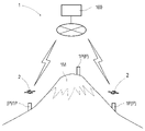
- Explanatory drawing which shows the structure of a system.
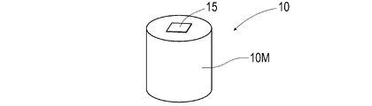
- a perspective view showing a reference post Perspective view of the magnetic marker.
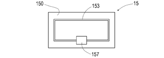
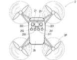
- Top view of the wireless tag Explanatory drawing which shows the structure of a drone.
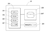
- the block diagram which shows the electrical composition of a control unit.
- Explanatory drawing which shows the structure of the sensor array.
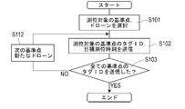
- a flow chart showing the flow of command information transmission processing by the management server.
- a flow chart showing the flow of positioning processing by a drone.
- Explanatory drawing of detection operation of a magnetic marker by a drone Explanatory drawing which illustrates the temporal change of the magnetic measurement value in the anteroposterior direction when a drone passes directly above a magnetic marker.
- Explanatory drawing which illustrates distribution of the magnetic measurement value in the width direction by magnetic sensors C1 to C15 when a drone is positioned right above a magnetic marker.
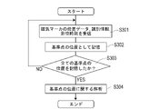
- a flow chart showing the flow of analysis processing by the server device.
- Explanatory drawing which shows other application example of a system.
- the system of a preferred embodiment of the present invention comprises a moving body including a magnetic sensor for measuring the magnitude of the acting magnetism.
- a detection unit that detects the magnetic marker by processing the magnetic measurement value by the magnetic sensor,
- a positioning unit that positions the moving body and
- a position specifying unit that specifies the position of the magnetic marker based on the position of the moving body positioned by the positioning unit when the magnetic marker is detected by the detecting unit.
- the system includes a storage unit that stores the position of the magnetic marker specified by the position specifying unit as the position of the reference point.
- a magnetic marker arranged at a reference point is detected using a moving body, and the position of the moving body when the magnetic marker is detected is positioned.
- the position of the magnetic marker is specified based on the position of the moving body and stored as the position of the reference point.
- it is not necessary to provide a configuration for executing positioning at each reference point and it is only necessary to provide a magnetic marker that can be detected by using a moving body at each reference point.
- the installation cost of each reference point is low, so that it is relatively easy to control the system cost.
- Example 1 This example is an example relating to a system 1 for positioning the reference point P by detecting the magnetic marker 10 provided at the reference point P with a drone 2 which is an example of a moving body. This content will be described with reference to FIGS. 1 to 14.
- the system 1 of this example is a system used for surveying the mountain body 1M as shown in FIGS. 1 and 2.
- reference points P are provided at a plurality of locations around the mountain body 1M, and reference posts 1P are erected at each reference point P.
- a magnetic marker 10 is installed on the upper end surface of each columnar reference post 1P.
- a drone an example of an unmanned aerial vehicle or a moving body
- the server device 100 capable of communicating with the drone 2 executes the management and analysis processing of the position data of the reference point P.
- (1) system configuration and (2) system operation will be described.
- the reference post 1P (Figs. 1 and 2) is a pillar of RC structure with a base diameter of about 1 m and an upper end surface diameter of about 20 cm, and is erected using the foundation that reaches the bedrock forming the mountain body 1M. ing.
- the reference post 1P is provided at a reference point P such as the mountaintop or the middle of the mountain body 1M.
- a reference point P such as the mountaintop or the middle of the mountain body 1M.
- the distances between the two reference posts 1P located opposite to each other across the mountaintop are specified, the crustal movement of the mountain body 1M such as expansion can be detected by the change in the distance.
- a reference post 1P is provided on a mountain body 1M where volcanic activity is dormant, it is possible to estimate the amount of magma accumulated inside, which is useful for predicting volcanic activity such as an eruption.
- the upper end surface of the reference post 1P is a flat surface. On the upper end surface thereof, for example, a pattern serving as a mark 11 such as a cross or a double circle is provided.
- the pattern serving as the mark 11 is useful for detecting, for example, the reference post 1P from the sky.
- the pattern may also be formed by a reflective material that reflects infrared light. If infrared light is projected from the drone 2 at night, the reference post 1P can be detected relatively easily by using the mark 11.
- an accommodating hole 110 which is a recess for accommodating the columnar magnetic marker 10 is provided.
- the magnetic marker 10 is held in a state of being substantially flush with the upper end surface.
- the magnetic marker 10 may be fixed by driving into the accommodating hole 110, adhering with an adhesive material, or the like, or may be accommodated in the accommodating hole 110 so that it can be inserted and removed.
- the magnetic marker 10 can be inserted and removed, the work such as regular maintenance and replacement of the magnetic marker 10 becomes easy.
- a plate on which a magnet can be attracted or a drone (an example of a moving body for maintenance) equipped with a magnet the magnetic marker 10 is lifted by a magnetic attraction force and pulled out from the accommodating hole 110 for recovery. Is also good.
- the magnetic marker 10 is arranged by dropping the magnetic marker 10 into the accommodating hole 110 by lowering the drone in a state where the magnetic marker 10 is magnetically attracted and suspended. It is also good to set up.
- the magnet on the drone side it is preferable to use an electromagnet or the like in which the north pole and the south pole can be exchanged or the magnetic force can be lost. If the electromagnet is capable of exchanging the north and south poles, the magnetic marker 10 can be pushed into the accommodating hole 110 by a magnetic reaction force.
- the magnetic marker 10 (FIG. 3) is a marker in which an RFID tag 15 (Radio Frequency IDentification Tag) is integrally held by a columnar magnet 10M having a diameter of 20 mm and a height of 28 mm. As described above, the magnetic marker 10 is held in the reference post 1P in a state of being accommodated in the accommodation hole 110 (FIG. 2) on the upper end surface of the reference post 1P.
- the magnet 10M forming the magnetic marker 10 is a ferrite plastic magnet in which magnetic powder of iron oxide, which is a magnetic material, is dispersed in a polymer material as a base material.
- the polymer material is, for example, Chlorinated Polyethylene, Poly Phenylene Sulfide-PPS, or the like.
- a sheet-shaped RFID tag 15 is arranged on the end face of the columnar magnet 10M.
- the RFID tag 15 is an electronic component that wirelessly outputs tag information.
- a coating layer made of a resin material may be provided on the surface.
- the coating layer may be a layer made of a composite material in which fibers are impregnated with a resin material.
- the RFID tag 15 may be arranged on the end face of the magnet 10M on which the coating layer is formed.
- a coating layer may be provided on all or part of the outer surface of the magnet 10M.
- the RFID tag 15 it is also possible to embed all or a part of the RFID tag 15 inside the magnet 10M.
- a sheet-shaped magnetic marker made of a magnet sheet may be adopted.
- it may be a magnetic marker in which two magnet sheets are bonded together.
- the sheet-shaped RFID tag 15 may be sandwiched between the two magnet sheets.
- the RFID tag 15 (FIG. 4) is an electronic component in which an IC chip 157 is mounted on the surface of a tag sheet 150 cut out from, for example, a PET (PolyEthylene Terephthalate) film.
- a print pattern of the antenna 153 is provided on the surface of the tag sheet 150.
- the antenna 153 has both an antenna function for feeding power that generates an exciting current by electromagnetic induction from the outside and an antenna function for communication that wirelessly transmits tag information.
- the RFID tag 15 operates by wireless external power supply, and outputs tag information such as tag ID, which is identification information, to the outside.
- the tag ID externally output by the RFID tag 15 can be used as the identification information of the magnetic marker 10 and the identification information of the reference point P (reference post 1P).
- the magnet 10M forming the magnetic marker 10 as described above is a magnet in which magnetic powder is dispersed in a polymer material. Since the magnet 10M has a large electrical internal resistance, there is little possibility that an eddy current is generated according to the wireless power supply to the RFID tag 15. Therefore, in the case of the magnetic marker 10 that employs this magnet 10M, electric power can be efficiently supplied to the RFID tag 15.
- the magnet 10M of this example constituting the magnetic marker 10 is suitable as a magnet for holding the RFID tag 15.
- Drone Drone 2 (FIGS. 5 and 6) is an unmanned aerial vehicle capable of flying by remote control or autopilot (autonomous control).
- the drone 2 of this example is a multicopter having four rotor blades 2P around the fuselage 2B.
- the drone 2 flies under the individual control of the four rotor blades 2P.
- the size of the body 2B of the drone 2 is about 30 cm in the front-rear direction and about 20 cm in the width.
- the body 2B of the drone 2 includes a control unit 20, an object detection sensor such as a millimeter wave radar 252 and an image sensor 251 and a sensor array 21 including a magnetic sensor Cn, a tag reader unit 241 that communicates with an RFID tag 15, a GPS unit 221 and an IMU. It is configured to include a positioning unit such as (Inertial Measurement Unit) 222 and a wireless communication unit 209 that communicates with the server device 100.
- a control unit 20 an object detection sensor such as a millimeter wave radar 252 and an image sensor 251 and a sensor array 21 including a magnetic sensor Cn
- a tag reader unit 241 that communicates with an RFID tag 15
- GPS unit 221 GPS unit 221
- IMU IMU
- It is configured to include a positioning unit such as (Inertial Measurement Unit) 222 and a wireless communication unit 209 that communicates with the server device 100.
- the millimeter wave radar 252 is an object detection sensor that uses millimeter waves with a wavelength of 1 to 10 mm and a frequency of 30 to 300 GHz.
- the millimeter wave radar 252 detects an object by using the reflected radio wave when the millimeter wave is transmitted, and measures the distance to the object.
- the millimeter-wave radar 252 is arranged so as to be able to monitor surrounding obstacles.
- the image sensor 251 is an object detection sensor including a camera for photographing the front and the bottom.
- the image sensor 251 includes a processing circuit (not shown) that performs image processing on an image captured by the camera.
- the image sensor 251 performs image processing on the captured image in front to detect an obstacle in front. Further, the image taken below is subjected to image processing to detect the mark 11 of the reference post 1P.
- the drone 2 of this example includes a GPS unit 221 capable of positioning an absolute position (two-dimensional position) and the like, and an IMU 222 capable of measuring acceleration, angular velocity, etc. as a positioning unit.
- the GPS unit 221 which is an example of the positioning unit is a unit that measures an absolute position by using GPS (Global Positioning System) which is a kind of GNSS (Global Navigation Satellite System).
- the GPS unit 221 is configured to position the center of the sensor array 21 attached along the width direction of the fuselage 2B.
- the magnetic sensor C8 is located at the center of the sensor array 21. It is not an essential requirement that the positioning position by the positioning unit is the center position of the sensor array 21.
- the position that serves as a reference for the amount of lateral displacement which will be described later, is set as the positioning position, but such a requirement is not essential.
- the relative positional relationship between the position that serves as the reference for the amount of strike-slip and the positioning position is specified, and it is sufficient that the position that serves as the reference for the amount of strike-slip can be specified based on the positioning position.
- the IMU 222 has a gyro sensor that measures angular velocities around three orthogonal axes, an acceleration sensor that measures acceleration in the three axes, and the like.
- the angular velocity and acceleration measured by the IMU 222 can be used for attitude control of the drone 2 and for autonomous flight by inertial navigation.
- the IMU 222 which is an example of the estimation unit, estimates the direction of the drone 2 by integrating the angular velocity and the like, and estimates the displacement amount of the drone 2 by the double integral of the acceleration and the like.
- the tag reader unit 241 is a communication unit that wirelessly communicates with the RFID tag 15 held by the magnetic marker 10 (see FIG. 3).
- the tag reader unit 241 wirelessly transmits the electric power required for the operation of the RFID tag 15 to operate the RFID tag 15 and read the tag ID (tag information) which is the identification information of the RFID tag 15.
- this tag ID is used as the identification information of the magnetic marker 10 and the identification information of the reference point P (reference post 1P).
- the wireless communication unit 209 is a unit for executing wireless communication with the server device 100 (see FIG. 1) via the Internet.
- the wireless communication unit 209 transmits the position data of the magnetic marker 10 and the like to the server device 100.
- the control unit 20 (FIG. 6) is a unit that controls various sensors and the like in addition to controlling the rotor blade 2P.
- the control unit 20 is an arithmetic unit including an electronic circuit 200.
- the electronic circuit 200 is equipped with electronic components such as a CPU (Central Processing Unit) 201, a ROM (Read Only Memory) 203, and a RAM (Random Access Memory) 205, and has an I / O unit (Input / Output) 207. It is a provided circuit.
- a storage device (storage medium) 208 such as a solid state drive (SSD), a wireless communication unit 209, or the like is connected to the electronic circuit 200.
- the control unit 20 has a function as a position specifying unit that identifies the position of the magnetic marker 10 based on the position of the drone (moving body) 2 positioned by the GPS unit 221 when the magnetic marker 10 is detected. ..
- the position data of the magnetic marker 10 is transmitted to the server device 100 and stored as the position of the reference point P.
- a map database (map DB) 208T is provided by using the storage area of the storage device 208.
- the map DB208T stores map data showing the arrangement of a drone base (not shown) provided with a parking space for the drone 2 to stand by, a mountain body 1M, a reference point P (see FIG. 1), and the like.
- the map data includes data on the absolute position of each position, data representing the terrain such as altitude and undulations, and data for identifying flight restricted areas.
- a reference point P is mapped to this map data.
- Each reference point P is associated with the tag ID of the RFID tag 15 attached to the magnetic marker 10. This tag ID is used as identification information of the reference point P (reference post 1P).
- the map data stored in the map DB 208T is used by the control unit 18 for determining a movement route and the like.
- control unit 20 it is also possible to configure the control unit 20 so that the real-time weather conditions such as wind speed and precipitation and the flight positions of other drones 2 can be received from the server device 100 at any time.
- the real-time weather conditions such as wind speed and precipitation
- the flight positions of other drones 2 can be received from the server device 100 at any time.
- a dynamic map that reflects real-time weather conditions and the like can be constructed, and flight control using the dynamic map becomes possible.
- the map DB208T may be provided in the server device 100 or the external device.
- the drone 2 can refer to the map DB208T at any time by using the wireless communication unit 209, so that the map DB208T and the like can be omitted from the configuration of the drone 2.
- the server device 100 provided with the map DB 208T may remotely control the drone 2 by remote control.
- the output signals of the positioning unit 22 and various sensors included in the drone 2 may be transmitted to the server device 100 or the like at any time.
- the sensor array 21 (FIGS. 5 and 7) is a unit including a magnetic sensor Cn for measuring the magnitude of the acting magnetism.
- the sensor array 21 of this example 15 magnetic sensors are arranged in a row at 1 cm intervals.
- the sensor array 21 includes a detection processing circuit 212 that executes detection processing of the magnetic marker 10 and the like.
- the detection processing circuit 212 which forms an example of the detection unit, detects the magnetic marker 10 by processing 15 magnetic measurement values output by the magnetic sensor Cn.
- a sensor array 21 is attached to the bottom surface of the body 2B of the drone 2 so that the lower magnetic source can be detected.
- the sensor array 21 is attached so that the arrangement direction of the magnetic sensors Cn coincides with the width direction (left-right direction) of the body 2B.
- the eighth magnetic sensor C8 in the middle is located at the center of the body 2B in the width direction. As described above, the position of the magnetic sensor C8 corresponds to the position determined by the GPS unit 221.
- the magnetic sensor Cn for example, a high-sensitivity MI sensor that detects magnetism by using a known MI effect (Magneto Impedance Effect) is suitable.
- the MI effect is an effect that the impedance of a magnetic sensitive body such as an amorphous wire changes sensitively according to an external magnetic field.
- each magnetic sensor to the sensor array 21 can detect the magnetic component in the front-rear direction and the magnetic component in the width direction of the body 2B (drone 2) so that each magnetic sensor Cn of the sensor array 21 can detect the magnetic component in the front-rear direction and the magnetic component in the width direction.
- the Cn is incorporated and the sensor array 21 is attached to the body 2B.
- a magnetic sensor that can detect magnetic components in the vertical direction in addition to the front-rear direction and the width direction of the body 2B may be used.
- the magnetic sensor may be capable of detecting only the magnetic component in the front-rear direction or only the magnetic component in the vertical direction.
- the MI sensor exemplified as the magnetic sensor Cn is a magnetic sensor having very excellent characteristics such as excellent spatial resolution, good responsiveness, and high sensitivity.
- By using such an MI sensor it is possible to suppress the magnetic force required for the magnetic marker arranged at the reference point P. Considering the influence on the natural world including wild animals and plants, the magnetic force of the magnetic marker arranged at the reference point P should be suppressed as much as possible. In such a case, an MI sensor that can suppress the magnetic force required for the magnetic marker to a small value is a selection close to the best.
- the server device 100 is a device for managing the position (absolute position) of the reference point P (reference post 1P), the distance between the reference points P, and the like.
- the server device 100 can exchange various data with the drone 2 via a public communication line such as the Internet.
- the server device 100 includes a main body including a storage device such as an electronic board or a hard disk drive on which a CPU is mounted, a monitor device such as a liquid crystal display, and an input device such as a keyboard and a mouse. ing.
- the operator can input the target positioning time of the reference point P or the like by using the input device.
- the server device 100 includes a storage unit that stores the position of the reference point P, a fluctuation identification unit that specifies the amount of time variation of the distance between the reference points P, and a notification unit that notifies that the activity of the mountain body 1M has become active. , Has the function as.
- the storage device which forms an example of the storage unit, stores the position of the magnetic marker 10 specified by the drone 2 as the position of the reference point P.
- the fluctuation identification unit is realized by a main body including a CPU.
- the main body of the server device 100 quantifies the difference between the positions of any two reference points P stored in the storage device, that is, the temporal variation of the distance between the two reference points P as the amount of variation.
- the amount of time variation of the distance between the two reference points exceeds the threshold value, for example, the display by the monitoring device (an example of the notification unit) of the server device 100 notifies that the volcanic activity is active.
- the quantity is illustrated.
- the fluctuation rate such as the ratio of the fluctuation amount over time and the ratio of the fluctuation amount to the distance between the two reference points P is used as a physical quantity representing the degree of change over time in the position of the reference point P. It is also good to identify. It is also possible to specify information indicating the change with time of the position of any one reference point P or a physical quantity representing the degree of change with time of the position of any one of the reference points P.
- the server device 100 lists the position information of the reference point P over the past predetermined period as information indicating the change over time of the position of the reference point P on the display screen of the display device by the server device 100 which is an example of the output unit. It is also good to display.
- the position information of the reference point P may be the position information of any one of the reference points P, or may be the information of the difference between the positions of any two reference points P.
- the position information of the reference point P may be printed and output by the server device 100, which is an example of the output unit, by using a printer, and the server device, which is an example of the output unit, stores a hard disk device, a USB memory, or the like.
- the position information may be output by recording in the area.
- FIG. 8 is a flow chart showing a flow of processing in which the server device 100 transmits command information to the drone 2.
- FIG. 9 is a flow chart showing a flow of processing in which the drone 2 positions the reference point P. 10 to 12 are reference views for explaining the flow chart of FIG. 9.
- FIG. 13 is a flow chart showing a flow of processing in which the server device 100 executes an analysis regarding the position of the reference point P.
- positioning of a plurality of reference points P is executed in parallel using a plurality of drones 2. Therefore, the process of FIG. 9 is executed in parallel by the plurality of drones 2.
- the server device 100 first selects the drone 2 for each reference point P to be positioned when positioning a plurality of reference points P (S101).
- the server device 100 transmits command information including identification information (tag ID) of the reference point P to be positioned, a target positioning time, and the like to the selected drone 2 (S102).
- identification information tag ID
- S102 target positioning time
- the process of step S102 above is repeatedly executed, and the positioning is executed.
- Command information is transmitted to the drone 2.
- control unit 20 of each drone 2 receives the command information including the identification information (tag ID) of the reference point P of the positioning target as shown in FIG. 9, the control unit 20 refers to the map data of the map DB 208T (FIG. 7) and is the positioning target.
- the reference point P of the above is specified and set as the destination (S201).
- the drone 2 moves toward the reference point P, which is the destination, by autonomous flight using inertial measurement values such as acceleration and angular velocity (S202).
- the drone 2 When the drone 2 reaches the sky above the reference post 1P, it processes the image taken by the downward camera and tries to detect the mark 11 on the upper end surface of the reference post 1P (S203).
- the drone 2 grasps the position of the reference point P to be positioned by detecting (image detection) the mark 11 of the reference post 1P in this way. Then, it stands by in a hovering state at a position offset in the horizontal direction from directly above the upper end surface of the reference post 1P so that positioning can be executed when the target positioning time is reached (see FIG. 10).
- the drone 2 When the target command time related to the command information is reached, the drone 2 is a sensor array arranged in the width direction (horizontal direction) while maintaining a height distance of about 10 cm from the reference post 1P as shown in FIG. It flies so as to scan the upper end surface by 21. The drone 2 attempts to detect the magnetic marker 10 during a flight moving forward as shown in the figure (S204). During the flight of the drone 2 as shown in FIG. 10, positioning by the GPS unit 221 is repeatedly executed.
- each magnetic sensor Cn of the sensor array 21 can measure the magnetic components in the front-rear direction and the width direction of the drone 2. For example, when this magnetic sensor Cn moves along the front-rear direction as shown in FIG. 11 and passes directly above the magnetic marker 10, the measured value (magnetic measurement value) of the magnetic component in the front-rear direction is magnetic as shown in FIG. The positive and negative directions are reversed before and after the marker 10, and the time changes so as to intersect zero at a position directly above the magnetic marker 10.
- the control unit 20 determines that the magnetic marker 10 has been detected when the sensor array 21 is located directly above the magnetic marker 10 and a zero cross Zc of magnetic measurement values in the front-rear direction occurs.
- the magnetic measurement value in FIG. 11 may be the sum of the magnetic measurement values of each magnetic sensor Cn (measurement values of magnetic components in the front-rear direction), or the maximum value among the magnetic measurement values of each magnetic sensor Cn. It may be.
- the magnetic sensor moves along a virtual line in the width direction passing directly above the magnetic marker 10.
- the measured values (magnetic measured values) of the magnetic components in the width direction are positive and negative reversed on both sides of the magnetic marker 10, and zeros intersect at a position directly above the magnetic marker 10. It changes like. Therefore, in the 15 magnetic sensors Cn arranged along the width direction in the sensor array 21, the positive / negative of the magnetic measurement value in the width direction detected by the magnetic sensor Cn depends on which side the magnetic marker 10 is located on. It will be different (Fig. 12).
- the control unit 20 can detect the magnetic marker 10 by the flight of the drone 2 illustrated in FIG. 10, that is, when the sensor array 21 is located directly above the magnetic marker 10, the magnetism in the width direction of each magnetic sensor Cn Capture the measured values (magnetic measured values) of the components.
- a zero cross Zc in which the positive and negative of the magnetic measurement values in the width direction are reversed appears directly above the magnetic marker 10.
- the position of the zero cross Zc represents the position of the magnetic marker 10 in the width direction.
- the position of the magnetic marker 10 in the width direction is, for example, the intermediate position between two magnetic sensors Cn adjacent to each other with the zero cross Zc in between, or the magnetic measurement of the magnetic sensors Cn on both outer sides when the magnetic measurement value in the width direction is zero. It can be specified as a position directly below the magnetic sensor Cn in which the positive and negative values are reversed.
- the control unit 20 measures the deviation of the drone 2 with respect to the magnetic marker 10 in the width direction (an example of a predetermined direction) as the amount of strike-slip.
- the magnetic sensor C8 at the center of the 15 magnetic sensors Cn constituting the sensor array 21 is located at the center of the drone 2.
- the control unit 20 specifies the amount of lateral displacement of the drone 2 with respect to the magnetic marker 10 with reference to the position of the central magnetic sensor C8. That is, in the configuration of this example, the position of the magnetic sensor C8 is a position that serves as a reference for the amount of lateral displacement.
- the example in the figure is an example in which the drone 2 is to the left with respect to the magnetic marker 10. The positive / negative of the amount of lateral displacement is positive when the drone 2 is moved to the left and negative when the drone 2 is moved to the right with respect to the magnetic marker 10.
- the drone 2 executes wireless power supply to the RFID tag 15 and reads the tag ID.
- the control unit 20 determines the detection of the magnetic marker 10 on the premise that the tag ID related to the command information and the tag ID read from the magnetic marker 10 match (S204 in FIG. 9). Further, the control unit 20 stores the positioning data by the GPS unit 221 when the magnetic marker 10 can be detected, that is, when the sensor array 21 is located directly above the magnetic marker 10.
- the GPS unit 221 measures the absolute position of the magnetic sensor C8 located at the center of the body 2B of the drone 2 in the width direction.
- the position of the magnetic sensor C8 which is a reference position for the amount of lateral displacement with respect to the magnetic marker 10
- the position of the positioning target is the position of the positioning target.
- another position that has a predetermined positional relationship with the position that serves as a reference for the amount of strike-slip and that can specify the reference position may be set as the positioning target.
- control unit 20 When the control unit 20 can detect the magnetic marker 10 (S204), the control unit 20 transmits the position data of the magnetic marker 10 to the server device 100 (S205). When transmitting the position data of the magnetic marker 10, the control unit 20 also transmits the identification information of the magnetic marker 10 (tag ID read when the magnetic marker 10 is detected) and the positioning time (S205).
- the position of the magnetic marker 10 is specified based on the positioning data stored at the time of detecting the magnetic marker 10 and the amount of strike-slip measured at the time of detecting the magnetic marker 10.
- the control unit 20 as a position specifying unit is a position obtained by subtracting the amount of lateral displacement specified at the time of detecting the magnetic marker 10 from the absolute position represented by the positioning data, that is, the absolute position of the magnetic sensor C8 at the time of detecting the magnetic marker 10.
- the position shifted by the amount of lateral displacement is specified as the position of the magnetic marker 10.
- the position of the magnetic sensor C8 is illustrated as a reference position of the lateral displacement amount, but the reference position of the lateral displacement amount is not limited to the position of the magnetic sensor C8 and may be any position.
- the drone 2 transmits the position data of the magnetic marker 10 (S205)
- the drone 2 moves toward the base by autonomous flight (S206). After that, the movement of the drone 2 ends by returning to the drone base (S207: Yes).
- the flight illustrated in FIG. 10 when the target positioning time related to the command information is reached, the flight illustrated in FIG. 10 is executed. Instead of this, the flight of FIG. 10 may be executed before the target positioning time, and the magnetic marker 10 may be detected in advance. Then, when the target positioning time is reached, the drone 2 may be controlled so as to be in a hovering state directly above the magnetic marker 10. In this case, when the target positioning time is reached, the positioning data of the GPS unit 221 can be acquired with high certainty, so that the accuracy of synchronization with the timing of positioning by the other drone 2 can be improved.
- the server device 100 when the server device 100 receives the position data (absolute position), identification information, and positioning time of the magnetic marker 10 from any of the drones 2 (S301), it stores them as the position of the reference point P at any time. (S302).
- the server device 100 stores the positions of all the reference points P to be positioned (S303: Yes)
- the server device 100 executes an analysis regarding the positions of the reference points P.
- the identification information among the received information from each drone 2 is used to identify which reference point P the position data of the received magnetic marker 10 corresponds to. Further, the same positioning time is used to confirm synchronization with the timing of positioning by another drone 2.
- the following description is a description when the synchronization of the positioning timing can be confirmed.
- the server device 100 specifies the amount of time variation of the distance between the reference points P, which is the difference between the positions of the two reference points P.
- the server device 100 as a notification unit performs threshold processing on this fluctuation amount, and when it exceeds a predetermined threshold, notifies the possibility that the activity of the mountain body 1M is active, for example, by displaying using a monitoring device. do.
- the positioning times for each reference point P match.
- similar positioning errors are included in the positions of two points that are simultaneously positioned. By taking the difference between the positions of the two points positioned at the same time, the positioning error can be canceled with high certainty, and the distance between the two reference points P can be specified with high accuracy.
- the positioning position of the reference point P is required to have high accuracy. Therefore, in this case, it is advisable to adopt a positioning method such as RTK (RealTimeKinematic) -GPS or DGPS (Differential Global Positioning System) that can ensure accuracy.
- RTK RealTimeKinematic
- DGPS Different Global Positioning System
- the server device 100 performs threshold processing on the amount of temporal fluctuation of the position of any one of the reference points P, and when the predetermined threshold is exceeded, for example, the activity of the mountain body 1M is active due to a display using a monitor device or the like. Notify the possibility that it is.
- the threshold processing for the fluctuation amount it is also possible to specify and quantify the fluctuation rate, which is the ratio of the fluctuation amount to the time, that is, the fluctuation rate. It is also possible to execute the above notification according to the result of the threshold processing regarding the volatility.
- a base station having a fixed position In addition, in order to improve the accuracy of positioning by the GPS unit 221, it is also good to use a base station having a fixed position. At the base station, positioning is carried out at any time using GPS. If positioning is executed at the base station in synchronization with the positioning by the drone 2, the relative position between the base station and the drone 2 can be specified with high accuracy. If the relative position of the drone 2 can be specified with high accuracy with reference to the base station, the positioning accuracy of the drone 2 can be improved.
- a configuration in which command information is transmitted to the drone 2 and location data is transmitted from the drone 2 to the server device 100 is executed via a public communication line such as the Internet, but this configuration is indispensable. is not. It is also possible to transmit command information to the drone 2 waiting at the drone base by Wi-Fi communication, infrared communication, or wired communication. Once the drone 2 stores the position data of the magnetic marker 10, the position data can be read out after returning to the drone base. In this case, wireless communication between the drone 2 and the server device 100 is not essential.
- the reference point P for monitoring the positional fluctuation can be realized at low cost. Unlike the conventional reference point in which a high-precision GPS unit is incorporated, at the reference point P of this example, it is only necessary to attach the magnetic marker 10.
- a positioning unit such as a GPS unit 221 is mounted on the drone 2 on the side that detects the magnetic marker 10 provided at the reference point P. Therefore, the positioning unit can be shared between a plurality of reference points to be surveyed, and the cost of the system can be reduced.
- the magnetic marker 10 including the RFID tag 15 is illustrated, but the RFID tag 15 is not an indispensable configuration. If the reference points P located adjacent to each other are sufficiently separated from each other and are not included in the error circle by GPS, the reference point P can be specified by the positioning by the GPS unit 221.
- the drone 2 is provided with the above-mentioned detection unit that executes the detection process of the magnetic marker 10, the above-mentioned position identification unit that specifies the position of the magnetic marker 10 based on the position positioned by the GPS unit 221, and the like. Is shown.
- the detection unit, the position identification unit, and the like can be provided not in the drone 2 but in the server device 100.
- the drone 2 may transmit the information necessary for the detection process of the magnetic marker 10 and the information necessary for specifying the position of the magnetic marker 10 to the server device 100 at any time.
- the position of the zero cross Zc is specified in the distribution of the magnetic measurement values in the width direction of each magnetic sensor Cn (for example, FIG. 12).
- This zero cross Zc has been described as a point where the positive and negative of the magnetic measurement value in the width direction are inverted, but the point where the positive and negative are inverted is unique when the magnetic measurement value contains an error or when the interval between the magnetic sensors Cn is narrow. It can be difficult to identify.
- the reference point P for surveying the mountain body 1M which is arranged around the mountain body 1M, is illustrated.
- a reference point P may be provided on the road 40.
- the sheet-shaped magnetic marker 10 (see FIG. 14) may be attached to the road surface, or the columnar magnetic marker may be arranged in the accommodating hole provided on the road surface.
- Examples of the moving body for positioning the reference point P on the road 40 include a vehicle 4 equipped with a magnetic sensor.
- the vehicle 4 illustrated in FIG. 14 is provided with a GPS unit, a communication unit, and the like.
- the GPS unit included in the vehicle 4 is a unit corresponding to RTK-GPS, and can position an absolute position with high accuracy.
- the vehicle 4 detects the magnetic marker 10 at the reference point P
- the vehicle 4 transmits the absolute position of the vehicle 4 at that time and the amount of lateral displacement of the vehicle 4 with respect to the magnetic marker 10 to an external server device (not shown).
- the absolute position of the magnetic marker 10 that is, the absolute position of the reference point P can be specified based on the absolute position of the vehicle 4 and the amount of lateral displacement of the vehicle 4 with respect to the magnetic marker 10.
- the position data of the reference point P can be collected only by disposing the magnetic marker 10 serving as the reference point P on the road 40, and the time-dependent change of the position of the reference point P is monitored. can. Further, the information on the inclination of the vehicle 4 in the roll direction when the magnetic marker 10 as the reference point P is detected, the information on the vehicle speed, the vibration, and the like are replaced with or added to the above-mentioned absolute position of the vehicle 4. It may also be sent to the server device. For example, based on the information of the inclination in the roll direction, the deformation of the pavement material such as a rut can be inferred.
- the server device it is preferable to store information on the quality of the pavement in association with the reference point P.
- a method of associating with the reference point P a method of associating the identification information of the reference point P with the information of the quality of the pavement state or a method of associating the position data of the reference point P with the information of the quality of the pavement state is stored. There are methods, etc.
- a vehicle having a plurality of wheels in the vehicle width direction and tilting according to the inclination of the road surface in the vehicle width direction is suitable as a vehicle for acquiring the above-mentioned information on the inclination in the roll direction.
- the vehicle may be provided with a recording unit that records the absolute position of the vehicle, the amount of lateral displacement, etc. when the magnetic marker 10 is detected. After the fact, if the data recorded in the recording unit is collected and aggregated, it is possible to generate data representing the change with time of the position of the reference point P.
- the moving object is equipped with an IMU, positioning by inertial navigation is possible.
- the IMU even if the magnetic marker is arranged in a place where satellite radio waves are hard to reach and GPS is difficult to use, the absolute position when the magnetic marker is detected can be specified. Therefore, if the mobile body is equipped with an IMU, even a magnetic marker arranged in a place where satellite radio waves are difficult to reach and GPS cannot be used can be used as a reference point.
- autonomous navigation such as a vehicle speed sensor that outputs a vehicle speed pulse according to the rotation of wheels, a mechanism that detects a movement vector by applying an optical mouse detection method, and a vehicle equipped with a yaw rate sensor that measures yaw rate. It is also good to adopt a vehicle capable of positioning as a moving body. As long as it is a moving body capable of positioning by autonomous navigation, even a magnetic marker arranged in a place where GPS is difficult to use can be used as a reference point.
- the reference point may be the reference point on the seabed.
- a moving body for positioning the reference point on the seabed for example, an underwater drone equipped with a magnetic sensor can be exemplified.
- a two-dimensional absolute position is illustrated as the position of the reference point P.
- a three-dimensional position obtained by adding the height to the two-dimensional absolute position may be adopted.
- crustal movements accompanied by uplift and subsidence of the reference point P can be detected at an early stage. It is also good to manage the height difference between different reference points P. It is also good to detect the fluctuation of the height difference and notify the fact.
- a drone 2 including a sensor array 21 can specify a two-dimensional magnetic distribution.
- the control unit 20 of the drone 2 specifies a two-dimensional magnetic distribution by combining a one-dimensional magnetic distribution composed of magnetic measurement values of 15 magnetic sensors Cn periodically output by the sensor array 21.
- the control unit as the distribution identification unit combines the one-dimensional magnetic distribution periodically output by the sensor array 21 by shifting the position by the amount of displacement estimated by IMU222 (an example of the estimation unit). Identify the dimensional magnetic distribution.
- the positioning data of the GPS unit 221, the measurement data by the IMU 222, and the magnetic measurement value of each magnetic sensor Cn output by the sensor array 21 may be transmitted to the server device 100 at any time.
- the server device 100 as the distribution specifying unit can specify the above-mentioned two-dimensional magnetic distribution.
- the configuration in which the drone 2 obtains the position data of the magnetic marker 10 by calculation and transmits it to the server device 100 has been described.
- the reception information of the satellite radio wave by the GPS unit 221 may be transmitted to the server device 100 at any time.
- the server device 100 obtains the position data by the calculation based on the received information of the satellite radio wave.
- the received information includes, for example, the reception time of the satellite radio wave, the information of the satellite that is the source of the satellite radio wave, the information indicating the phase of the satellite radio wave, the information indicating the phase difference of a plurality of satellite radio waves received at the same time, and the like. , There are various types of information used in calculations for positioning.
- the one-dimensional magnetic distribution by the sensor array 21 by one magnetic sensor.
- the control unit as the distribution identification unit is one-dimensional by combining the magnetic measurement values periodically output by one magnetic sensor while shifting the position by the amount of displacement estimated by IMU222 (an example of the estimation unit). It is good to specify a magnetic distribution.
- it is also possible to specify the two-dimensional magnetic distribution by specifying the one-dimensional magnetic distribution for each position while changing the position in the front-rear direction. It is also possible to acquire a two-dimensional magnetic distribution by using a sensor array in which magnetic sensors Cn are arranged two-dimensionally.
Landscapes
- Physics & Mathematics (AREA)
- General Physics & Mathematics (AREA)
- Engineering & Computer Science (AREA)
- Radar, Positioning & Navigation (AREA)
- Remote Sensing (AREA)
- Computer Networks & Wireless Communication (AREA)
- Control Of Position, Course, Altitude, Or Attitude Of Moving Bodies (AREA)
Abstract
基準点Pの位置を管理するためのシステム(1)は、周辺に磁気を作用するように基準点Pに設けられた磁気マーカと、磁気マーカを検出するための磁気センサ、及び測位のためのGPSユニットを備えるドローン(2)と、基準点Pの位置を記憶するサーバ装置(100)と、を含めて構成されており、ドローン(2)は、磁気マーカを検出したときのGPSユニットによる測位データに基づいて磁気マーカの位置を特定し、サーバ装置(100)は、ドローン(2)によって特定された磁気マーカの位置を、基準点Pの位置として記憶する。
Description
本発明は、基準点の位置を管理するためのシステムに関する。
従来より、例えば、山体や海溝などの地殻変動の監視が必要な箇所や、ダムや橋やビルや道路などの構造物の時間的な変化を監視する必要がある箇所等には、測位対象となる基準点が設けられることがある。例えば、山体などでの地殻変動を監視するGNSS(Global Navigation Satellite System)連続観測システムが知られている。このGNSS連続観測システムでは、衛星電波の受信機や無線通信機等が組み込まれた電子基準点が採用されている(例えば、特許文献1参照。)。
GNSSシステムの各電子基準点は、定期的に衛星電波を受信し、衛星電波の受信情報や測位結果である位置データ等を外部のサーバ装置に送信する。GNSSシステムでは、各電子基準点の位置等がサーバ装置によって管理される。例えば、サーバ装置は、一の電子基準点の位置の変動や、異なる電子基準点間の距離の変動等を監視する。そして、サーバ装置は、基準点に関する位置的なデータの経時変化等に基づいて、例えば、火山活動や地震などの地殻変動の予兆を検出する。
しかしながら、前記従来の基準点の測位システムでは、各基準点に高精度の受信機や通信装置を設ける必要があるため、インフラコストの抑制が容易ではないという問題がある。
本発明は、前記従来の問題点に鑑みてなされたものであり、インフラコストを抑制可能な基準点のシステムを提供しようとするものである。
本発明は、基準点の位置を管理するためのシステムであって、
周辺に磁気を作用するように前記基準点に設けられた磁気マーカと、
前記磁気マーカの位置を、前記基準点の位置として記憶する記憶部と、
前記基準点の位置の経時変化を表す情報を出力する出力部と、を備えるシステムにある。
周辺に磁気を作用するように前記基準点に設けられた磁気マーカと、
前記磁気マーカの位置を、前記基準点の位置として記憶する記憶部と、
前記基準点の位置の経時変化を表す情報を出力する出力部と、を備えるシステムにある。
本発明のシステムは、磁気マーカの位置が基準点の位置として記憶し、基準点の位置の経時変化を表す情報を出力可能なシステムである。
本発明のシステムでは、周囲に磁気を作用する磁気マーカが基準点に配設されている。このシステムでは、測位を実行する構成を各基準点に組み込む代わりに、磁気的に検出可能な磁気マーカが各基準点に配設されている。このシステムでは、各基準点の設置コストが安価になるので、システムコストの抑制が比較的容易である。
本発明の好ましい態様のシステムは、作用する磁気の大きさを計測する磁気センサを備える移動体と、
前記磁気センサによる磁気計測値に処理を施して前記磁気マーカを検出する検出部と、
該移動体の位置を測位する測位部と、
前記検出部により前記磁気マーカが検出されたときに前記測位部が測位した前記移動体の位置に基づいて当該磁気マーカの位置を特定する位置特定部と、
該位置特定部が特定した前記磁気マーカの位置を、前記基準点の位置として記憶する記憶部と、を備えるシステムにある。
前記磁気センサによる磁気計測値に処理を施して前記磁気マーカを検出する検出部と、
該移動体の位置を測位する測位部と、
前記検出部により前記磁気マーカが検出されたときに前記測位部が測位した前記移動体の位置に基づいて当該磁気マーカの位置を特定する位置特定部と、
該位置特定部が特定した前記磁気マーカの位置を、前記基準点の位置として記憶する記憶部と、を備えるシステムにある。
このシステムでは、移動体を利用して基準点に配設された磁気マーカが検出され、磁気マーカが検出されたときの移動体の位置が測位される。このシステムでは、移動体の位置に基づいて磁気マーカの位置が特定され、基準点の位置として記憶される。このシステムでは、測位を実行する構成を各基準点に設ける必要がなく、移動体を利用して検出可能な磁気マーカを各基準点に設けるだけで良い。このシステムでは、各基準点の設置コストが安価になるので、システムコストの抑制が比較的容易である。
本発明の実施の形態につき、以下の実施例を用いて具体的に説明する。
(実施例1)
本例は、基準点Pに設けられた磁気マーカ10を、移動体の一例であるドローン2で検出することにより基準点Pを測位するためのシステム1に関する例である。この内容について、図1~図14を用いて説明する。
(実施例1)
本例は、基準点Pに設けられた磁気マーカ10を、移動体の一例であるドローン2で検出することにより基準点Pを測位するためのシステム1に関する例である。この内容について、図1~図14を用いて説明する。
本例のシステム1は、図1及び図2に示すごとく、山体1Mの測量に用いられるシステムである。このシステム1では、山体1M周辺の複数個所に基準点Pが設けられ、各基準点Pには基準ポスト1Pが立設されている。柱状の各基準ポスト1Pの上端面には、磁気マーカ10が設置されている。システム1では、測位機能を備えるドローン(無人航空機、移動体の一例)2が磁気マーカ10を検出することにより、基準点Pの測位(位置の測定)可能である。このシステム1では、ドローン2と通信可能なサーバ装置100によって基準点Pの位置データの管理や解析処理が実行される。以下、(1)システム構成、及び(2)システム動作について説明する。
(1)システム構成
本例のシステム1を構成する、基準ポスト1P、磁気マーカ10、ドローン2、サーバ装置100について、順番に説明する。
本例のシステム1を構成する、基準ポスト1P、磁気マーカ10、ドローン2、サーバ装置100について、順番に説明する。
(基準ポスト)
基準ポスト1P(図1、図2)は、基部の直径が約1mで、上端面の直径が約20cmのRC構造の柱であり、山体1Mをなす岩盤に達する基礎を利用して立設されている。基準ポスト1Pは、例えば、山頂や、山体1Mの中腹などの基準点Pに設けられている。例えば、山頂を挟んで対向して位置する2か所の基準ポスト1P間の距離を特定すれば、距離の変化により、膨張などの山体1Mの地殻変動を検知できる。例えば火山活動が休眠中の山体1Mに基準ポスト1Pを設ければ、内部に溜まったマグマの量などの推定が可能となり、噴火などの火山活動の予測に役立つ。
基準ポスト1P(図1、図2)は、基部の直径が約1mで、上端面の直径が約20cmのRC構造の柱であり、山体1Mをなす岩盤に達する基礎を利用して立設されている。基準ポスト1Pは、例えば、山頂や、山体1Mの中腹などの基準点Pに設けられている。例えば、山頂を挟んで対向して位置する2か所の基準ポスト1P間の距離を特定すれば、距離の変化により、膨張などの山体1Mの地殻変動を検知できる。例えば火山活動が休眠中の山体1Mに基準ポスト1Pを設ければ、内部に溜まったマグマの量などの推定が可能となり、噴火などの火山活動の予測に役立つ。
基準ポスト1Pの上端面は、平坦面をなしている。その上端面には、例えば、十字、二重丸などの目印11となる模様が設けられている。目印11となる模様は、例えば基準ポスト1Pを上空から検出するために役立つ。赤外光を反射する反射材料により模様を形成することも良い。夜間にドローン2から赤外光を投光すれば、目印11を利用して基準ポスト1Pを比較的容易に検出できる。
基準ポスト1Pの上端面の中央には、円柱状の磁気マーカ10を収容するための窪みである収容孔110が設けられている。基準ポスト1Pでは、この収容孔110に磁気マーカ10を収容することで、上端面に対して略面一をなす状態で磁気マーカ10が保持される。磁気マーカ10は、収容孔110への打込、接着材料による接着等により固定された状態であっても良いし、挿抜可能に収容孔110に収容された状態であっても良い。
なお、磁気マーカ10を挿抜可能であれば、磁気マーカ10の定期的なメンテナンスや交換等の作業が容易になる。磁石が吸着可能な板や磁石を搭載する図示しないドローン(メンテナンス用の移動体の一例。)を利用して、磁気的な吸着力によって磁気マーカ10を吊り上げて収容孔110から抜き取って回収することも良い。収容孔110に磁気マーカ10を配置するに当たっては、磁気マーカ10を磁気的に吸着して吊り下げている状態のドローンの下降により、収容孔110に磁気マーカ10を落とし込むことにより磁気マーカ10を配設することも良い。この場合、ドローン側の磁石として、N極とS極とを入替可能であったり、磁力を失わせることが可能な電磁石等を採用すると良い。N極とS極とを入替可能な電磁石であれば、磁気的な反力により、磁気マーカ10を収容孔110に押し込むことが可能となる。
(磁気マーカ)
磁気マーカ10(図3)は、直径20mm、高さ28mmの柱状をなす磁石10Mにより、RFIDタグ15(Radio Frequency IDentification Tag、無線タグ)が一体的に保持されたマーカである。上記の通り、磁気マーカ10は、基準ポスト1Pの上端面の収容孔110(図2)に収容された状態で基準ポスト1Pに保持される。磁気マーカ10をなす磁石10Mは、磁性材料である酸化鉄の磁粉を基材である高分子材料中に分散させたフェライトプラスチックマグネットである。高分子材料は、例えば、塩素化ポリエチレン(Chlorinated Polyethylene)、ポリフェニレンスルファイド(Poly Phenylene Sulfide - PPS)等である。
磁気マーカ10(図3)は、直径20mm、高さ28mmの柱状をなす磁石10Mにより、RFIDタグ15(Radio Frequency IDentification Tag、無線タグ)が一体的に保持されたマーカである。上記の通り、磁気マーカ10は、基準ポスト1Pの上端面の収容孔110(図2)に収容された状態で基準ポスト1Pに保持される。磁気マーカ10をなす磁石10Mは、磁性材料である酸化鉄の磁粉を基材である高分子材料中に分散させたフェライトプラスチックマグネットである。高分子材料は、例えば、塩素化ポリエチレン(Chlorinated Polyethylene)、ポリフェニレンスルファイド(Poly Phenylene Sulfide - PPS)等である。
磁気マーカ10では、柱状の磁石10Mの端面に、シート状のRFIDタグ15が配置されている。RFIDタグ15は、無線によりタグ情報を出力する電子部品である。なお、磁石10Mの端面にRFIDタグ15を配置した後、樹脂材料によるコーティング層を表面に設けることも良い。コーティング層としては、繊維に樹脂材料を含浸させた複合材料よりなる層であっても良い。あるいは、コーティング層が形成された磁石10Mの端面に、RFIDタグ15を配設しても良い。磁石10Mの外表面の全部あるいは一部に、コーティング層を設けることも良い。
さらに、磁石10Mの内部に、RFIDタグ15の全部又は一部を埋設することも良い。柱状の磁気マーカ10に代えて、磁石シートよりなるシート状の磁気マーカを採用しても良い。この場合、磁石シートの表面にシート状のRFIDタグ15を貼付して配置すると良い。さらに、2枚の磁石シートを貼り合わせた磁気マーカであっても良い。この場合、2枚の磁石シートによってシート状のRFIDタグ15を挟み込むことも良い。
RFIDタグ15(図4)は、例えばPET(PolyEthylene Terephthalate)フィルムから切り出したタグシート150の表面にICチップ157が実装された電子部品である。タグシート150の表面には、アンテナ153の印刷パターンが設けられている。アンテナ153は、外部からの電磁誘導によって励磁電流が発生する給電用のアンテナ機能と、タグ情報を無線送信する通信用のアンテナ機能と、を併せ持っている。RFIDタグ15は、無線による外部給電により動作し、識別情報であるタグIDなどのタグ情報を外部出力する。RFIDタグ15が外部出力するタグIDは、磁気マーカ10の識別情報および基準点P(基準ポスト1P)の識別情報として利用できる。
なお、上記のように磁気マーカ10をなす磁石10Mは、磁粉を高分子材料中に分散させた磁石である。この磁石10Mは、電気的な内部抵抗が大きいため、RFIDタグ15に対する無線による電力供給に応じて渦電流が発生するおそれが少ない。それ故、この磁石10Mを採用する磁気マーカ10の場合、RFIDタグ15に対して効率良く電力を供給できる。磁気マーカ10を構成する本例の磁石10Mは、RFIDタグ15を保持する磁石として好適である。
(ドローン)
ドローン2(図5及び図6)は、遠隔操作あるいは自動操縦(自律制御)により飛行可能な無人航空機である。本例のドローン2は、胴体2Bの周りに4つの回転翼2Pを備えるマルチコプターである。ドローン2は、4つの回転翼2Pの個別制御により飛行する。なお、ドローン2の胴体2Bの大きさは、前後約30cm、幅約20cmである。
ドローン2(図5及び図6)は、遠隔操作あるいは自動操縦(自律制御)により飛行可能な無人航空機である。本例のドローン2は、胴体2Bの周りに4つの回転翼2Pを備えるマルチコプターである。ドローン2は、4つの回転翼2Pの個別制御により飛行する。なお、ドローン2の胴体2Bの大きさは、前後約30cm、幅約20cmである。
ドローン2の胴体2Bには、制御ユニット20、ミリ波レーダ252や画像センサ251などの物体検出センサ、磁気センサCnを含むセンサアレイ21、RFIDタグ15と通信するタグリーダユニット241、GPSユニット221やIMU(Inertial Measurement Unit)222などの測位ユニット、及びサーバ装置100と通信する無線通信ユニット209等を含めて構成されている。
ミリ波レーダ252は、波長1~10mm、周波数30~300GHzのミリ波を利用する物体検出センサである。ミリ波レーダ252は、ミリ波を送信したときの反射電波を利用して対象物を検出すると共に、対象物までの距離を計測する。なお、ミリ波レーダ252は、周囲の障害物を監視可能に配設されている。
画像センサ251は、前方及び下方を撮影するためのカメラを含む物体検出センサである。画像センサ251は、カメラによる撮影画像に画像処理を施す処理回路(図示略)等を含めて構成されている。画像センサ251は、前方の撮影画像に画像処理を施して、前方の障害物を検出する。また、下方の撮影画像に画像処理を施して、基準ポスト1Pの目印11を検出する。
上記のごとく本例のドローン2は、測位ユニットとして、絶対位置(2次元的な位置)等を測位可能なGPSユニット221、及び加速度や角速度等を計測可能なIMU222を備えている。測位部の一例であるGPSユニット221は、GNSS(Global Navigation Satellite System、衛星測位システム)の一種であるGPS(Global Positioning System)を利用して絶対位置を測定するユニットである。GPSユニット221は、胴体2Bの幅方向に沿って取り付けられる上記のセンサアレイ21の中央の位置を測位するように構成されている。後述する通り、本例のドローン2では、センサアレイ21の中央に磁気センサC8が位置している。なお、測位部による測位位置は、センサアレイ21の中央の位置であることは必須の要件ではない。本例では、後述する横ずれ量の基準となる位置を、測位位置に設定しているが、このよう要件も必須ではない。横ずれ量の基準となる位置と測位位置との相対的な位置関係が特定されており、測位位置に基づき、横ずれ量の基準となる位置を特定できれば良い。
IMU222は、直交する3軸回りの角速度を計測するジャイロセンサや、3軸方向の加速度を計測する加速度センサ等を有している。IMU222が計測する角速度や加速度は、ドローン2の姿勢制御に利用可能であるほか、慣性航法による自律飛行に利用できる。推定部の一例をなすIMU222は、角速度の積分等によりドローン2の方位を推定し、加速度の2重積分等によりドローン2の変位量を推定する。
タグリーダユニット241は、磁気マーカ10(図3参照。)に保持されたRFIDタグ15と無線で通信する通信ユニットである。タグリーダユニット241は、RFIDタグ15の動作に必要な電力を無線で送電してRFIDタグ15を動作させ、RFIDタグ15の識別情報であるタグID(タグ情報)を読み取る。上記のごとく、このタグIDは、磁気マーカ10の識別情報、及び基準点P(基準ポスト1P)の識別情報として利用される。
無線通信ユニット209は、インターネットを介してサーバ装置100(図1参照。)との間の無線通信を実行するためのユニットである。無線通信ユニット209は、磁気マーカ10の位置データ等をサーバ装置100に送信する。
制御ユニット20(図6)は、回転翼2Pの制御に加えて、各種センサ等を制御するユニットである。制御ユニット20は、電子回路200を備える演算ユニットである。電子回路200は、CPU(Central Processing Unit)201やROM(Read Only Memory)203やRAM(Random Access Memory)205などの電子部品が実装されていると共に、I/O部(Input/Output)207が設けられた回路である。電子回路200には、ソリッドステートドライブ(SSD)等の記憶装置(記憶媒体)208や無線通信ユニット209等が接続されている。
制御ユニット20は、磁気マーカ10が検出されたときにGPSユニット221が測位したドローン(移動体)2の位置に基づいて、磁気マーカ10の位置を特定する位置特定部としての機能を備えている。なお、磁気マーカ10の位置データは、サーバ装置100に送信され、基準点Pの位置として記憶される。
制御ユニット20では、記憶装置208の記憶領域を利用して、地図データベース(地図DB)208Tが設けられている。地図DB208Tには、ドローン2が待機する駐機スペースが設けられた図示しないドローン基地、山体1M、基準点P(図1参照。)の配置等を表す地図データが保存されている。
地図データには、各位置の絶対位置のデータが含まれていると共に、高度や起伏などの地形を表すデータや、飛行制限区域などを特定するためのデータ等が含まれている。この地図データには、基準点Pがマッピングされている。各基準点Pには、磁気マーカ10に付設されたRFIDタグ15のタグIDがひも付けされている。このタグIDは、基準点P(基準ポスト1P)の識別情報として利用される。地図DB208Tに保存された地図データは、制御ユニット18が移動ルートを決定等するために利用される。
なお、風速や降水量などのリアルタイムの気象状況や、他のドローン2の飛行位置などをサーバ装置100から随時、受信可能なように、制御ユニット20を構成することも良い。この場合には、リアルタイムの気象状況等が反映されたダイナミックマップを構築でき、ダイナミックマップを利用した飛行制御が可能になる。
また、サーバ装置100あるいは外部装置に、地図DB208Tを設けることも良い。この場合には、ドローン2が、無線通信ユニット209を利用して随時、地図DB208Tを参照可能に構成することで、ドローン2の構成から地図DB208T等を省略できる。あるいは、地図DB208Tを備えるサーバ装置100が遠隔制御によりドローン2を遠隔的に操作することも良い。この場合、ドローン2が備える測位ユニット22や各種センサの出力信号を、サーバ装置100等に随時、送信すると良い。
上記のセンサアレイ21(図5及び図7)は、作用する磁気の大きさを計測する磁気センサCnを含めて構成されたユニットである。本例のセンサアレイ21では、15個の磁気センサが1cm間隔で一列に配列にされている。センサアレイ21は、磁気マーカ10の検出処理等を実行する検出処理回路212を含めて構成されている。検出部の一例をなす検出処理回路212は、磁気センサCnが出力する15個の磁気計測値を処理することにより磁気マーカ10を検出する。
ドローン2では、下方の磁気発生源を検出できるよう、ドローン2の胴体2Bの底面にセンサアレイ21が取り付けられている。センサアレイ21は、磁気センサCnの配列方向が胴体2Bの幅方向(左右方向)に一致するように取り付けられている。磁気センサC1~C15のうち、真ん中の8番目の磁気センサC8が、胴体2Bの幅方向の中央に位置している。なお、上記の通り、磁気センサC8の位置は、GPSユニット221が測位する位置に当たる。
磁気センサCnとしては、例えば、公知のMI効果(Magneto Impedance Effect)を利用して磁気を検出する高感度のMIセンサなどが好適である。MI効果は、例えばアモルファスワイヤなどの感磁体のインピーダンスが外部磁界に応じて敏感に変化するという効果である。本例では、センサアレイ21の各磁気センサCnが、胴体2B(ドローン2)の前後方向の磁気成分と、幅方向の磁気成分と、を検出可能なように、センサアレイ21への各磁気センサCnの組込み、及び胴体2Bへのセンサアレイ21の取付がなされている。なお、胴体2Bの前後方向及び幅方向に加えて鉛直方向の磁気成分を検出可能な磁気センサであっても良い。あるいは、前後方向の磁気成分のみ、あるいは鉛直方向の磁気成分のみを検出可能な磁気センサであっても良い。
なお、磁気センサCnとして例示するMIセンサは、空間分解能が優れ、応答性が良好で、高感度である、という非常に優れた特性を有する磁気センサである。このようなMIセンサを利用すれば、基準点Pに配設する磁気マーカに要求される磁力を抑えることができる。野生の動物や植物などを含む自然界への影響を考慮した場合、基準点Pに配設する磁気マーカの磁力は極力抑えるべきである。このような場合において、磁気マーカに必要な磁力を小さく抑制できるMIセンサは、ベストに近い選択である。
(サーバ装置)
サーバ装置100は、基準点P(基準ポスト1P)の位置(絶対位置)や、基準点P間の距離等、を管理するための装置である。サーバ装置100は、インターネットなどの公衆通信回線を介してドローン2と間で各種データのやり取りが可能である。図示は省略するが、サーバ装置100は、CPUが実装された電子基板やハードディスクドライブなどの記憶装置などを備える本体と、液晶ディスプレイなどのモニタ装置と、キーボードやマウスなどの入力装置と、を備えている。サーバ装置100では、例えば、オペレータが入力装置を利用して基準点Pの目標測位時刻等を入力可能である。
サーバ装置100は、基準点P(基準ポスト1P)の位置(絶対位置)や、基準点P間の距離等、を管理するための装置である。サーバ装置100は、インターネットなどの公衆通信回線を介してドローン2と間で各種データのやり取りが可能である。図示は省略するが、サーバ装置100は、CPUが実装された電子基板やハードディスクドライブなどの記憶装置などを備える本体と、液晶ディスプレイなどのモニタ装置と、キーボードやマウスなどの入力装置と、を備えている。サーバ装置100では、例えば、オペレータが入力装置を利用して基準点Pの目標測位時刻等を入力可能である。
サーバ装置100は、基準点Pの位置を記憶する記憶部、基準点P間の距離の時間的な変動量を特定する変動特定部、山体1Mの活動が活発になったことを報知する報知部、としての機能を備えている。記憶部の一例をなす記憶装置は、ドローン2によって特定された磁気マーカ10の位置を、基準点Pの位置として記憶する。変動特定部は、CPUを備える本体によって実現される。
サーバ装置100の本体は、記憶装置が記憶するいずれか2つの基準点Pの位置の差、すなわち2つの基準点P間の距離の時間的な変動を、変動量として定量化する。2つの基準点間の距離の時間的な変動量が閾値を超えたとき、例えばサーバ装置100のモニタ装置(報知部の一例)による表示により、火山活動が活発化している旨が報知される。
本例では、基準点Pの位置の経時変化を表す情報の一例、及び基準点Pの位置の経時変化の度合いを表す物理量として、上記のいずれか2つの基準点Pの位置の差である変動量を例示している。この変動量に代えて、時間的な変動量の割合や、2つの基準点P間の距離に対する変動量の割合等、の変動率を、基準点Pの位置の経時変化の度合いを表す物理量として特定することも良い。いずれか一の基準点Pの位置の経時変化を表す情報や、いずれか一の基準点Pの位置の経時変化の度合いを表す物理量を特定することも良い。
関係者が所持するスマートフォン等の携帯端末への報知機能を、サーバ装置100に具備させることも良い。サーバ装置100が、基準点Pの位置の経時変化を表す情報として、過去所定期間に亘る基準点Pの位置情報を、出力部の一例をなすサーバ装置100がディスプレイ装置の表示画面上にて一覧表示することも良い。基準点Pの位置情報は、いずれか一の基準点Pの位置情報であっても良く、いずれか2つの基準点Pの位置の差の情報であっても良い。さらに、基準点Pの位置情報を、出力部の一例をなすサーバ装置100がプリンタを利用して印字出力することも良く、出力部の一例をなすサーバ装置が、ハードディスク装置やUSBメモリ等の記憶領域に記録することにより位置情報を出力しても良い。
(2)システム動作
システム1による測位動作について、図8~図13を参照して説明する。図8は、サーバ装置100がドローン2に対して指令情報を送信する処理の流れを示すフロー図である。図9は、ドローン2が基準点Pを測位する処理の流れを示すフロー図である。図10~図12は、図9のフロー図を説明する際の参照図である。図13は、サーバ装置100が基準点Pの位置に関する解析を実行する処理の流れを示すフロー図である。システム1では、複数の基準点Pの測位が、複数のドローン2を利用して並行して実行される。したがって、図9の処理は、複数のドローン2により並行して実行される。
システム1による測位動作について、図8~図13を参照して説明する。図8は、サーバ装置100がドローン2に対して指令情報を送信する処理の流れを示すフロー図である。図9は、ドローン2が基準点Pを測位する処理の流れを示すフロー図である。図10~図12は、図9のフロー図を説明する際の参照図である。図13は、サーバ装置100が基準点Pの位置に関する解析を実行する処理の流れを示すフロー図である。システム1では、複数の基準点Pの測位が、複数のドローン2を利用して並行して実行される。したがって、図9の処理は、複数のドローン2により並行して実行される。
サーバ装置100は、図8のごとく、複数の基準点Pを測位するに当たって、まず、測位対象の基準点P毎にドローン2を選択する(S101)。サーバ装置100は、選択したドローン2に対して、測位対象の基準点Pの識別情報(タグID)や目標測位時刻などを含む指令情報を送信する(S102)。このようにして測位対象の基準点Pの全てについて、基準点P及びドローン2の組合せを更新しながら(S103:No→S112)、上記のステップS102の処理を繰り返し実行し、測位を実行する各ドローン2に指令情報を送信する。
各ドローン2の制御ユニット20は、図9のごとく、測位対象の基準点Pの識別情報(タグID)を含む指令情報を受信すると、地図DB208T(図7)の地図データを参照して測位対象の基準点Pを特定し、目的地として設定する(S201)。ドローン2は、加速度や角速度などの慣性計測値などを利用する自律的な飛行により、目的地である基準点Pに向けて移動する(S202)。
ドローン2は、基準ポスト1Pの上空に到達すると、下向きのカメラによる撮影画像に処理を施し、基準ポスト1Pの上端面の目印11の検出を試みる(S203)。ドローン2は、このように基準ポスト1Pの目印11を画像的に検出(画像検出)することで、測位対象の基準点Pの位置を把握する。そして、目標測位時刻になったときに測位を実行できるよう、基準ポスト1Pの上端面の真上から水平方向にオフセットした位置において、ホバリング状態で待機する(図10参照。)。
ドローン2は、指令情報に係る目標指令時刻になると、図10のごとく、基準ポスト1Pとの高さ方向の間隔を約10cm程度に維持しつつ、幅方向(左右方向)に配列されたセンサアレイ21により上端面をスキャンするように飛行する。ドローン2は、同図のように前方に移動する飛行中に、磁気マーカ10の検出を試みる(S204)。なお、図10のようなドローン2の飛行中、GPSユニット221による測位が繰り返し実行される。
ここで、磁気マーカ10の検出方法、及び横ずれ量の計測方法について説明する。上記のごとく、センサアレイ21の各磁気センサCnは、ドローン2の前後方向及び幅方向の磁気成分を計測可能である。例えばこの磁気センサCnが、図11のごとく前後方向に沿って移動して磁気マーカ10の真上を通過するとき、前後方向の磁気成分の計測値(磁気計測値)は、図11のごとく磁気マーカ10の前後で正負が反転すると共に、磁気マーカ10の真上の位置でゼロを交差するように時間的に変化する。ドローン2が前後方向に沿って移動している間、いずれかの磁気センサCnが検出する前後方向の磁気計測値について、その正負が反転するゼロクロスZcが生じたとき、センサアレイ21が磁気マーカ10の真上に位置すると判断できる。制御ユニット20は、センサアレイ21が磁気マーカ10の真上に位置し、前後方向の磁気計測値のゼロクロスZcが生じたとき、磁気マーカ10を検出したと判断する。なお、図11の磁気計測値は、各磁気センサCnの磁気計測値(前後方向の磁気成分の計測値)の総和であっても良いし、各磁気センサCnの磁気計測値のうちの最大値であっても良い。
また、例えば、磁気センサCnと同じ仕様の磁気センサについて、磁気マーカ10の真上を通過する幅方向の仮想線に沿う移動を想定する。この場合、図12のごとく、幅方向の磁気成分の計測値(磁気計測値)は、磁気マーカ10を挟んだ両側で正負が反転すると共に、磁気マーカ10の真上の位置でゼロを交差するように変化する。したがって、センサアレイ21において幅方向に沿って配列された15個の磁気センサCnでは、磁気マーカ10を介してどちらの側にあるかによって磁気センサCnが検出する幅方向の磁気計測値の正負が異なってくる(図12)。
制御ユニット20は、図10に例示するドローン2の飛行により磁気マーカ10を検出できたとき、すなわち、センサアレイ21が磁気マーカ10の真上に位置したとき、各磁気センサCnの幅方向の磁気成分の計測値(磁気計測値)を取り込む。各磁気センサCnの幅方向の磁気計測値の分布(例えば図12)では、幅方向の磁気計測値の正負が反転するゼロクロスZcが磁気マーカ10の真上に現れる。ゼロクロスZcの位置は、磁気マーカ10の幅方向の位置を表している。磁気マーカ10の幅方向の位置は、例えば、ゼロクロスZcを挟んで隣り合う2つの磁気センサCnの中間の位置、あるいは幅方向の磁気計測値がゼロであって両外側の磁気センサCnの磁気計測値の正負が反転している磁気センサCnの直下の位置として特定可能である。
制御ユニット20は、磁気マーカ10に対するドローン2の幅方向(所定の方向の一例。)の偏差を横ずれ量として計測する。本例では、センサアレイ21を構成する15個の磁気センサCnのうちの中央の磁気センサC8が、ドローン2の中央に位置している。制御ユニット20は、中央の磁気センサC8の位置を基準として、磁気マーカ10に対するドローン2の横ずれ量を特定する。つまり、本例の構成では、磁気センサC8の位置が、横ずれ量の基準となる位置となっている。
例えば図12の磁気分布の場合、磁気マーカ10に対応するゼロクロスZcの位置がC9とC10との中間辺りのC9.5に相当する位置となっている。上記のように磁気センサC9とC10の間隔は1cmであるから、磁気マーカ10に対するドローン2の横ずれ量は(9.5-8)×1cm=1.5cmとなる。同図の例は、ドローン2が磁気マーカ10に対して左寄りとなった場合の例である。なお、横ずれ量の正負は、磁気マーカ10に対してドローン2が左に寄った場合を正、右に寄った場合を負としている。
ドローン2は、図10の飛行中、RFIDタグ15に対する無線給電を実行し、タグIDの読取を実行する。制御ユニット20は、指令情報に係るタグIDと、磁気マーカ10から読み取ったタグIDと、の一致を前提として、磁気マーカ10の検出を確定させる(図9中のS204)。また、制御ユニット20は、磁気マーカ10を検出できたとき、すなわち磁気マーカ10の真上にセンサアレイ21が位置したときのGPSユニット221による測位データを記憶する。ここで、上記の通り、GPSユニット221は、ドローン2の胴体2Bの幅方向の中央に位置する磁気センサC8の絶対位置を測定する。つまり、本例の構成では、磁気マーカ10に対する横ずれ量の基準となる位置である磁気センサC8の位置が、測位対象の位置となっている。これに代えて、横ずれ量の基準となる位置と所定の位置関係にあって、当該基準となる位置を特定可能な他の位置を測位対象としても良い。
制御ユニット20は、磁気マーカ10を検出できた場合(S204)、磁気マーカ10の位置データをサーバ装置100に送信する(S205)。なお、制御ユニット20は、磁気マーカ10の位置データを送信する際、磁気マーカ10の識別情報(磁気マーカ10の検出時に読み取ったタグID)、及び測位時刻を併せて送信する(S205)。
ここで、磁気マーカ10の位置は、磁気マーカ10の検出時に記憶された測位データ、及び磁気マーカ10の検出時に計測された横ずれ量に基づいて特定される。位置特定部としての制御ユニット20は、測位データが表す絶対位置、すなわち磁気マーカ10を検出したときの磁気センサC8の絶対位置から、磁気マーカ10の検出時に特定された横ずれ量を差し引いた位置(横ずれ量の分だけずらした位置)を、磁気マーカ10の位置として特定する。なお、横ずれ量の基準となる位置として、磁気センサC8の位置を例示するが、横ずれ量の基準となる位置は、磁気センサC8の位置には限定されずどのような位置であっても良い。
ドローン2は、磁気マーカ10の位置データを送信すると(S205)、自律飛行により基地に向かって移動する(S206)。その後、ドローン2の移動は、ドローン基地への帰還により終了する(S207:Yes)。
なお、本例では、指令情報に係る目標測位時刻になったときに、図10に例示する飛行を実行する。これに代えて、目標測位時刻よりも前に図10の飛行を実行し、予め磁気マーカ10を検出しておくことも良い。そして、目標測位時刻になったとき、磁気マーカ10の真上でホバリング状態となるようにドローン2を制御すると良い。この場合には、目標測位時刻になったとき、GPSユニット221の測位データを確実性高く取得できるので、他のドローン2による測位のタイミングとの同期の精度を向上できる。
サーバ装置100は、図13のごとく、いずれかのドローン2から磁気マーカ10の位置データ(絶対位置)、識別情報、測位時刻を受信すると(S301)、随時、基準点Pの位置等として記憶する(S302)。サーバ装置100は、測位対象の全ての基準点Pの位置を記憶すると(S303:Yes)、基準点Pの位置に関する解析を実行する。なお、各ドローン2からの受信情報のうちの識別情報は、受信した磁気マーカ10の位置データがいずれの基準点Pに係るものかを特定するために利用される。また、同様の測位時刻は、他のドローン2による測位のタイミングとの同期を確認するために利用される。以下の説明は、測位のタイミングの同期を確認できた場合の説明である。
基準点Pの位置に関する解析としては、例えば、2つの基準点P間の距離の時間的な変動を特定する解析等がある。基準点P間の距離の時間的な変動を特定する解析によれば、例えばマグマ溜まりによる山体1Mの膨張などを高精度に検知でき、火山活動を精度高く予知できる。サーバ装置100は、いずれか2つの基準点Pの位置の差分である基準点P間の距離の時間的な変動量を特定する。報知部としてのサーバ装置100は、この変動量に閾値処理を施し、所定の閾値を超えたとき、例えばモニタ装置を利用する表示等により、山体1Mの活動が活発になっている可能性を報知する。
なお、2つの基準点P間の距離を特定するに当たっては、各基準点Pに関する測位時刻の一致が重要になる。GPSの測位原理に鑑み、同時に測位された2地点の位置については、同様の測位誤差が含まれる可能性が高い。同時に測位された2地点の位置の差分をとれば、測位誤差を確実性高く相殺でき、2つの基準点P間の距離を精度高く特定できる。
また、基準点Pの位置に関する解析としては、例えば、各基準点Pの位置の時間的な変動を特定する解析がある。ひとつの基準点Pの位置の時間的な変動を特定するためには、測位時点が異なる2つの位置データを対象として、差分をとる必要がある。このとき、測位時点が異なれば、測位された各位置データに包含される測位誤差が異なっている可能性が高い。それ故、基準点Pの位置の時間的な変動を特定する解析においては、基準点Pの測位位置に高い精度が要求される。そこで、この場合には、RTK(Real Time Kinematic)-GPSや、DGPS(Differential Global Positioning System)など、精度が確保できる測位方法を採用すると良い。
サーバ装置100は、いずれか一の基準点Pの位置の時間的な変動量について閾値処理を施し、所定の閾値を超えたとき、例えばモニタ装置を利用する表示等により、山体1Mの活動が活発になっている可能性を報知する。なお、変動量に関する閾値処理に代えて、時間に対する変動量の割合である変動率、すなわち変動速度として特定して定量化することも良い。変動率に関する閾値処理の結果に応じて、上記のような報知を実行することも良い。
なお、GPSユニット221による測位の精度を向上するため、位置が固定された基地局を利用することも良い。基地局では、GPSを利用して測位が随時、実施される。ドローン2による測位と同期して、基地局で測位を実行すれば、基地局とドローン2との相対位置を高精度に特定可能となる。基地局を基準としてドローン2の相対位置を高精度に特定できれば、ドローン2による測位精度を向上できる。
本例では、ドローン2に対する指令情報の送信や、ドローン2からサーバ装置100への位置データの送信等が、インターネット等の公衆通信回線を介して実行される構成を例示したが、この構成は必須ではない。ドローン基地で待機中のドローン2に対して、Wi-Fi通信や、赤外線通信や、有線による通信によって、指令情報を送信することも良い。ドローン2が磁気マーカ10の位置データを一旦記憶していれば、ドローン基地への帰還後にその位置データを読み出し可能である。この場合、ドローン2とサーバ装置100との無線通信が必須ではなくなる。
以上のように構成された本例のシステム1によれば、位置的な変動を監視するための基準点Pを低コストで実現できる。高精度なGPSユニットが組み込まれた従来の基準点とは異なり、本例の基準点Pでは、磁気マーカ10を取り付けるだけで良い。本例の構成では、基準点Pに設けられた磁気マーカ10を検出する側のドローン2にGPSユニット221等の測位ユニットが搭載されている。そのため、測量対象の複数の基準点等の間で、測位ユニットを共用可能であり、システムのコストを低減できる。
なお、本例では、RFIDタグ15を備える磁気マーカ10を例示したが、RFIDタグ15は、必須の構成ではない。隣り合って位置する基準点Pが十分に離れており、GPSによる誤差円の範囲内に含まれることがなければ、GPSユニット221による測位によって、基準点Pの特定が可能である。
なお、本例では、磁気マーカ10の検出処理を実行する上記の検出部や、GPSユニット221が測位した位置に基づいて磁気マーカ10の位置を特定する上記の位置特定部等、を備えるドローン2を示している。検出部や位置特定部等は、ドローン2ではなく、サーバ装置100に設けることもできる。この場合、磁気マーカ10の検出処理に必要な情報や、磁気マーカ10の位置を特定するために必要な情報等を、ドローン2がサーバ装置100に随時、送信すれば良い。
なお、本例では、磁気マーカ10に対するドローン2の横ずれ量を計測するに当たって、各磁気センサCnの幅方向の磁気計測値の分布(例えば図12)において、ゼロクロスZcの位置を特定している。このゼロクロスZcは、幅方向の磁気計測値の正負が反転する点として説明したが、磁気計測値に誤差が含まれる場合や、磁気センサCnの間隔が狭い場合等、正負が反転する点を一意に特定することが難しくなる場合がある。
そこで、各磁気センサCnの幅方向の磁気計測値の分布を曲線近似することも良い。近似曲線であれば、ゼロクロスZcの特定が容易である。あるいは、幅方向の磁気計測値の分布を表す理想的な分布曲線として、振幅や周期が異なる複数種類の曲線を想定することも良い。各磁気センサCnの幅方向の磁気計測値の分布と最も相関の高い曲線を、複数種類の曲線の中から選択すると良い。理想的な分布曲線であれば、ゼロクロスZcの特定が容易である。
本例では、山体1Mの周辺に配置され、山体1Mを測量するための基準点Pを例示している。これに代えて、図14に例示する通り、道路40に基準点Pを設けることも良い。道路40の基準点Pの位置的な変動を監視すれば、道路の損傷や地盤の緩み等を早期に検知できる。道路40の基準点Pの場合、シート状の磁気マーカ10(図14参照。)を路面に貼付しても良く、路面に設けた収容孔に柱状の磁気マーカを配置しても良い。道路40の基準点Pを測位する移動体としては、例えば、磁気センサを備える車両4等がある。
例えば、図14に例示する車両4は、GPSユニットや通信ユニット等を備えている。車両4が備えるGPSユニットは、RTK-GPSに対応するユニットであり、精度高く絶対位置を測位可能である。車両4は、基準点Pの磁気マーカ10を検出したとき、そのときの車両4の絶対位置、及び磁気マーカ10に対する車両4の横ずれ量を、外部のサーバ装置(図示略)に送信する。サーバ装置においては、車両4の絶対位置、及び磁気マーカ10に対する車両4の横ずれ量に基づいて、磁気マーカ10の絶対位置、すなわち基準点Pの絶対位置を特定可能である。
このように図14のシステム1では、基準点Pとなる磁気マーカ10を道路40に配設しておくのみで、基準点Pの位置データを収集でき、基準点Pの位置の経時変化を監視できる。さらに、基準点Pとしての磁気マーカ10を検出したときの車両4のロール方向の傾きの情報や、車速や振動などの情報を、上記の車両4の絶対位置等に代えて、あるいは加えて、サーバ装置に送信することも良い。例えば、ロール方向の傾きの情報に基づけば、例えば轍などの舗装材料の変形を推測できる。また例えば、車速や振動などの情報に基づけば、各基準点Pについて、轍やひび割れや凹みなど舗装状態の良否を推測できる。サーバ装置では、基準点Pに対応付けて、舗装状態の良否の情報を記憶すると良い。基準点Pに対応付ける方法としては、基準点Pの識別情報を対応付けて舗装状態の良否の情報を記憶する方法や、基準点Pの位置データを対応付けて舗装状態の良否の情報を記憶する方法、等がある。なお、車幅方向に複数の輪を有しており、車幅方向における路面の傾きに応じて車両が傾く車両は、上記のロール方向の傾きの情報を取得する車両として好適である。
なお、通信ユニットに代えて、あるいは加えて、磁気マーカ10を検出したときの車両の絶対位置や横ずれ量等を記録する記録ユニットを備える車両であっても良い。事後的に、記録ユニットに記録されたデータを回収して集約すれば、基準点Pの位置の経時変化を表すデータを生成可能である。
なお、IMUを備える移動体であれば、慣性航法による測位が可能である。IMUによれば、衛星電波が届きにくくGPSの利用が難しい場所に配設された磁気マーカであっても、その磁気マーカが検出されたときの絶対位置を特定できる。それ故、IMUを備える移動体であれば、衛星電波が届きにくくGPSの利用が難しい場所に配設された磁気マーカであっても、基準点として利用できる。
さらに、車輪の回転に応じて車速パルスを出力する車速センサや、光学式マウスの検出方式を応用して移動ベクトルを検出する仕組みや、ヨーレートを計測するヨーレートセンサ等を備える車両など、自律航法による測位が可能な車両を移動体として採用することも良い。自律航法による測位が可能な移動体であれば、GPSの利用が難しい場所に配設された磁気マーカであっても、基準点として利用できる。
さらに、基準点としては、海底の基準点であっても良い。この場合には、基準点の測位により、海底の地殻変動等を早期に検知可能である。海底の基準点を測位するための移動体としては、例えば、磁気センサを備える水中ドローンを例示できる。また、建物や橋やダムなどの構造物に、本例の基準点を設けることも良い。この場合には、構造物の形状や寸法の経時変化を精度高く検出できる。
本例では、基準点Pの位置として、2次元的な絶対位置を例示している。基準点Pの位置として、2次元的な絶対位置に高さを加えた3次元的な位置を採用することも良い。この場合には、基準点Pの隆起や沈降などを伴う地殻変動を早期に検出できるようになる。異なる基準点P間の高低差を管理することも良い。高低差の変動を検出し、その旨を報知することも良い。
なお、基準点Pの磁気マーカ10に対面するエリアにおける2次元的な磁気分布を特定することも良い。このような2次元的な磁気分布では、図11及び図12を参照して上述した方法と同様に、磁気マーカ10の位置を特定できる。例えば、センサアレイ21を備えるドローン2によって、2次元的な磁気分布を特定することが可能である。このドローン2の制御ユニット20は、センサアレイ21が周期的に出力する15個の磁気センサCnの磁気計測値よりなる1次元的な磁気分布を組み合わせて2次元的な磁気分布を特定する。分布特定部としての制御ユニットは、センサアレイ21が周期的に出力する1次元的な磁気分布を、IMU222(推定部の一例)が推定する変位量の分だけ位置をずらしながら組み合わせることで、2次元的な磁気分布を特定する。
なお、GPSユニット221の測位データ、IMU222による計測データ、センサアレイ21が出力する各磁気センサCnの磁気計測値を、随時、サーバ装置100に送信することも良い。この場合には、分布特定部としてのサーバ装置100において、上記の2次元的な磁気分布を特定できる。また、本例では、ドローン2が磁気マーカ10の位置データを演算により求めて、サーバ装置100に送信する構成を説明した。この構成に代えて、GPSユニット221による衛星電波の受信情報を、随時サーバ装置100に送信することも良い。この場合、サーバ装置100が、衛星電波の受信情報に基づく演算により位置データを求めると良い。なお、受信情報には、例えば、衛星電波の受信時刻や、衛星電波の送信元の衛星の情報や、衛星電波の位相を表す情報や、同時に受信した複数の衛星電波の位相差を表す情報など、測位のための演算に利用される各種の情報がある。
さらになお、センサアレイ21による1次元的な磁気分布を1つの磁気センサによって特定することも可能である。例えば、ドローンの幅方向の飛行(移動)によって、センサアレイ21が出力する1次元的な磁気分布と同様の磁気分布を特定することができる。分布特定部としての制御ユニットは、1つの磁気センサが周期的に出力する磁気計測値を、IMU222(推定部の一例)が推定する変位量の分だけ位置をずらしながら組み合わせることで、1次元的な磁気分布を特定すると良い。さらに、前後方向の位置を変更しながら1次元の磁気分布を位置毎に特定することにより、2次元の磁気分布を特定することも良い。なお、磁気センサCnが2次元的に配列されたセンサアレイを利用して2次元的な磁気分布を取得することも良い。
以上、実施例のごとく本発明の具体例を詳細に説明したが、これらの具体例は、特許請求の範囲に包含される技術の一例を開示しているにすぎない。言うまでもなく、具体例の構成や数値等によって、特許請求の範囲が限定的に解釈されるべきではない。特許請求の範囲は、公知技術や当業者の知識等を利用して前記具体例を多様に変形、変更あるいは適宜組み合わせた技術を包含している。
1 システム
1M 山体
1P 基準ポスト
2 ドローン(移動体)
10 磁気マーカ
20 制御ユニット(位置特定部)
21 センサアレイ
212 検出処理回路(検出部)
100 サーバ装置(記憶部、変動特定部、報知部、出力部)
208 記憶装置
221 GPSユニット(測位部、測位ユニット)
222 IMU(推定部、測位ユニット)
Cn 磁気センサ
1M 山体
1P 基準ポスト
2 ドローン(移動体)
10 磁気マーカ
20 制御ユニット(位置特定部)
21 センサアレイ
212 検出処理回路(検出部)
100 サーバ装置(記憶部、変動特定部、報知部、出力部)
208 記憶装置
221 GPSユニット(測位部、測位ユニット)
222 IMU(推定部、測位ユニット)
Cn 磁気センサ
Claims (13)
- 基準点の位置を管理するためのシステムであって、
周辺に磁気を作用するように前記基準点に配設された磁気マーカと、
前記磁気マーカの位置を、前記基準点の位置として記憶する記憶部と、
前記基準点の位置の経時変化を表す情報を出力する出力部と、を備えるシステム。 - 請求項1において、1箇所あるいは2箇所以上の複数の前記基準点の位置の経時変化の度合いを物理量に換算する変動特定部と、
前記物理量が所定の閾値を超えたときに報知を実行する報知部と、を備えるシステム。 - 請求項2において、前記変動特定部が前記物理量に換算する対象の経時変化は、前記記憶部がいずれか一の基準点について記憶している位置の経時変化、及び前記記憶部がいずれか2つの基準点について記憶する位置の差分である当該いずれか2つの基準点間の距離の経時変化、のうちの少なくともいずれか一方であるシステム。
- 請求項2または3において、前記物理量は、変動量あるいは変動率であるシステム。
- 請求項1~4のいずれか1項において、作用する磁気の大きさを計測する磁気センサを備える移動体と、
前記磁気センサによる磁気計測値に処理を施して前記磁気マーカを検出する検出部と、
該移動体の位置を測位する測位部と、
前記検出部により前記磁気マーカが検出されたときに前記測位部が測位した前記移動体の位置に基づいて当該磁気マーカの位置を特定する位置特定部と、を備え、
前記記憶部は、前記位置特定部により特定された磁気マーカの位置を、前記基準点の位置として記憶しているシステム。 - 請求項5において、前記測位部は、衛星測位システムを利用して測位を実行するように構成されているシステム。
- 請求項5または6において、前記移動体は、前記磁気センサが1次元的あるいは2次元的に配列されたセンサアレイを備えているシステム。
- 請求項5~7のいずれか1項において、前記移動体の移動に伴う変位量を推定する推定部と、
磁気の大きさの位置的な分布である磁気分布を特定する分布特定部と、を含み、
該分布特定部は、前記推定部が推定した変位量および前記磁気センサによる磁気計測値に基づいて複数の位置における磁気の大きさを特定して前記磁気分布を特定するシステム。 - 請求項5~8のいずれか1項において、前記移動体は、遠隔的な操作あるいは自律制御による移動が可能であるシステム。
- 請求項5~9のいずれか1項において、前記磁気マーカは、車両が走行する道路に敷設され、前記移動体は、少なくとも、道路を走行する車両であるシステム。
- 請求項5~10のいずれか1項において、前記基準点には、画像的に検出可能な目印が設けられており、
前記移動体は、前記基準点の目印を検出するための画像センサを備えているシステム。 - 請求項5~11のいずれか1項において、前記移動体は、傾き又は振動を計測可能な車両であって、前記基準点は、車両が走行する道路に設けられ、
前記記憶部は、前記基準点の位置に加えて、前記車両が計測した傾きまたは振動の情報、あるいは当該情報に基づいて推測された舗装状態の良否の情報を、当該基準点に対応付けて記憶するシステム。 - 請求項5~12のいずれか1項において、前記検出部は、前記移動体に相対する前記磁気マーカの所定の方向の横ずれ量を特定可能であり、
前記測位部は、前記検出部が特定する前記横ずれ量の基準となる位置、あるいは当該横ずれ量の基準となる位置を特定可能な位置を、前記移動体の位置として測位し、
前記位置特定部は、前記検出部により前記磁気マーカが検出されたときに前記測位部が測位した前記移動体の位置に基づき、前記横ずれ量の基準となる位置を特定し、当該横ずれ量の基準となる位置から前記検出部が特定した横ずれ量の分だけずらした位置を磁気マーカの位置として特定するシステム。
Priority Applications (1)
| Application Number | Priority Date | Filing Date | Title |
|---|---|---|---|
| JP2022575658A JPWO2022154104A1 (ja) | 2021-01-18 | 2022-01-14 |
Applications Claiming Priority (2)
| Application Number | Priority Date | Filing Date | Title |
|---|---|---|---|
| JP2021-005594 | 2021-01-18 | ||
| JP2021005594 | 2021-01-18 |
Publications (1)
| Publication Number | Publication Date |
|---|---|
| WO2022154104A1 true WO2022154104A1 (ja) | 2022-07-21 |
Family
ID=82448498
Family Applications (1)
| Application Number | Title | Priority Date | Filing Date |
|---|---|---|---|
| PCT/JP2022/001231 Ceased WO2022154104A1 (ja) | 2021-01-18 | 2022-01-14 | システム |
Country Status (2)
| Country | Link |
|---|---|
| JP (1) | JPWO2022154104A1 (ja) |
| WO (1) | WO2022154104A1 (ja) |
Citations (4)
| Publication number | Priority date | Publication date | Assignee | Title |
|---|---|---|---|---|
| JP2004340831A (ja) * | 2003-05-16 | 2004-12-02 | Mitsubishi Electric Corp | 地面の異常検出方法及び異常検出装置 |
| JP2015212621A (ja) * | 2014-04-17 | 2015-11-26 | 善郎 水野 | マーカ装置を含むシステム及びこれを利用した方法 |
| JP2018206106A (ja) * | 2017-06-06 | 2018-12-27 | 愛知製鋼株式会社 | マーカシステム及び運用方法 |
| KR102173589B1 (ko) * | 2020-08-31 | 2020-11-04 | 조은석 | 드론을 이용한 측량 시스템 |
-
2022
- 2022-01-14 WO PCT/JP2022/001231 patent/WO2022154104A1/ja not_active Ceased
- 2022-01-14 JP JP2022575658A patent/JPWO2022154104A1/ja active Pending
Patent Citations (4)
| Publication number | Priority date | Publication date | Assignee | Title |
|---|---|---|---|---|
| JP2004340831A (ja) * | 2003-05-16 | 2004-12-02 | Mitsubishi Electric Corp | 地面の異常検出方法及び異常検出装置 |
| JP2015212621A (ja) * | 2014-04-17 | 2015-11-26 | 善郎 水野 | マーカ装置を含むシステム及びこれを利用した方法 |
| JP2018206106A (ja) * | 2017-06-06 | 2018-12-27 | 愛知製鋼株式会社 | マーカシステム及び運用方法 |
| KR102173589B1 (ko) * | 2020-08-31 | 2020-11-04 | 조은석 | 드론을 이용한 측량 시스템 |
Also Published As
| Publication number | Publication date |
|---|---|
| JPWO2022154104A1 (ja) | 2022-07-21 |
Similar Documents
| Publication | Publication Date | Title |
|---|---|---|
| Khan et al. | A comparative survey of lidar-slam and lidar based sensor technologies | |
| CN111983936B (zh) | 一种无人机半物理仿真系统及测评方法 | |
| CN106061836B (zh) | 控制装置、成像装置、控制方法、成像方法和计算机程序 | |
| US20200233095A1 (en) | Accuracy of global navigation satellite system based positioning using high definition map based localization | |
| NL2013724B1 (en) | Underwater positioning system. | |
| Brenner | Extraction of features from mobile laser scanning data for future driver assistance systems | |
| KR102013802B1 (ko) | 드론을 이용한 하천 하상 지형 조사 시스템 및 그 구동방법 | |
| Martinez et al. | UAS point cloud accuracy assessment using structure from motion–based photogrammetry and PPK georeferencing technique for building surveying applications | |
| US10319247B2 (en) | Aerial vehicle navigation method | |
| US20240013134A1 (en) | Mobile transport platform | |
| CN111323789B (zh) | 一种基于无人机和固态雷达的地面形貌扫描装置及方法 | |
| KR101678744B1 (ko) | 영상식 차량검지기의 성능평가를 위한 교통정보 수집장치 및 원격 모니터링 시스템 | |
| CN106062510A (zh) | 信息处理装置、信息处理方法和计算机程序 | |
| Al-Darraji et al. | A technical framework for selection of autonomous uav navigation technologies and sensors | |
| CN106291535A (zh) | 一种障碍物检测装置、机器人及避障系统 | |
| KR20210039750A (ko) | 드론을 이용한 지하 공간 실시간 3차원(3d) 매핑시스템 | |
| JP6553023B2 (ja) | 洪水状況のラグランジュ監視システム及び方法 | |
| US10241194B2 (en) | Mobile device utilizing time of flight for personal security and localization | |
| KR102608741B1 (ko) | 지피에스(gps)를 이용한 지하시설물 측량 조사시스템 | |
| EP3333664A2 (en) | Aerial vehicle navigation method | |
| CN202975840U (zh) | 远程监控系统 | |
| WO2022154104A1 (ja) | システム | |
| Sniatala | Drone as a sensors’ platform | |
| US20120027251A1 (en) | Device with markings for configuration | |
| CN208536829U (zh) | 城市区域地面沉降多源感知自动化监控系统 |
Legal Events
| Date | Code | Title | Description |
|---|---|---|---|
| 121 | Ep: the epo has been informed by wipo that ep was designated in this application |
Ref document number: 22739509 Country of ref document: EP Kind code of ref document: A1 |
|
| ENP | Entry into the national phase |
Ref document number: 2022575658 Country of ref document: JP Kind code of ref document: A |
|
| NENP | Non-entry into the national phase |
Ref country code: DE |
|
| 122 | Ep: pct application non-entry in european phase |
Ref document number: 22739509 Country of ref document: EP Kind code of ref document: A1 |