WO2022153591A1 - 車両制御装置、車両システム、更新システム - Google Patents
車両制御装置、車両システム、更新システム Download PDFInfo
- Publication number
- WO2022153591A1 WO2022153591A1 PCT/JP2021/032908 JP2021032908W WO2022153591A1 WO 2022153591 A1 WO2022153591 A1 WO 2022153591A1 JP 2021032908 W JP2021032908 W JP 2021032908W WO 2022153591 A1 WO2022153591 A1 WO 2022153591A1
- Authority
- WO
- WIPO (PCT)
- Prior art keywords
- program
- vehicle
- control device
- data
- vehicle control
- Prior art date
- Legal status (The legal status is an assumption and is not a legal conclusion. Google has not performed a legal analysis and makes no representation as to the accuracy of the status listed.)
- Ceased
Links
Images


Classifications
-
- G—PHYSICS
- G06—COMPUTING OR CALCULATING; COUNTING
- G06F—ELECTRIC DIGITAL DATA PROCESSING
- G06F8/00—Arrangements for software engineering
- G06F8/60—Software deployment
- G06F8/65—Updates
-
- G—PHYSICS
- G06—COMPUTING OR CALCULATING; COUNTING
- G06F—ELECTRIC DIGITAL DATA PROCESSING
- G06F11/00—Error detection; Error correction; Monitoring
- G06F11/07—Responding to the occurrence of a fault, e.g. fault tolerance
- G06F11/0703—Error or fault processing not based on redundancy, i.e. by taking additional measures to deal with the error or fault not making use of redundancy in operation, in hardware, or in data representation
- G06F11/079—Root cause analysis, i.e. error or fault diagnosis
-
- G—PHYSICS
- G07—CHECKING-DEVICES
- G07C—TIME OR ATTENDANCE REGISTERS; REGISTERING OR INDICATING THE WORKING OF MACHINES; GENERATING RANDOM NUMBERS; VOTING OR LOTTERY APPARATUS; ARRANGEMENTS, SYSTEMS OR APPARATUS FOR CHECKING NOT PROVIDED FOR ELSEWHERE
- G07C5/00—Registering or indicating the working of vehicles
- G07C5/008—Registering or indicating the working of vehicles communicating information to a remotely located station
Definitions
- the present invention relates to a technique for updating a program executed by a vehicle control device that controls the operation of a vehicle.
- the vehicle control device (Electronic Control Unit: ECU) that controls the vehicle is interconnected in the in-vehicle network.
- ECU Electronic Control Unit
- FOTA Wireless On The Air
- Examples of transmitting data from the center to the vehicle include FOTA (Firmware On The Air) that updates the ECU program, update of map data of car navigation, music data distribution, and the like.
- An example of transmitting data from a vehicle to a center is to upload vehicle parts diagnostic information to the center, contact the dealer with the diagnostic information on the center side, and replace vehicle parts (parts management).
- Patent Document 1 describes an example in which the traveling status of a vehicle is collected in the vehicle and the collected log is uploaded to the center.
- the vehicle collection function is changed by distributing a data collection program from the center to the vehicle.
- the log collection conditions, the log collection frequency, the upload transmission frequency, and the like can be changed.
- information that has not been collected by the vehicle can be transmitted to the center by adding the application function of the ECU by OTA.
- This allows the vehicle to collect these logs, send them to the center, and the center to analyze the information, for example, in applications such as the route information of a courier company and the operation information of each customer of a taxi. ..
- the function required for the application to output the new information may be insufficient.
- both the ECU in which the application is mounted and another ECU in which the data collection function is mounted are updated by the OTA.
- the present invention has been made in view of the above problems, and it is possible to easily manage the software state of the ECU and to match the management information of the software state in each of the vehicle and the center to create an ECU application and a data collection program.
- the purpose is to provide program update technology that can be updated in cooperation.
- the vehicle control device aggregates the first update state of the first program executed by the vehicle control device and the second update state of the second program executed by the second vehicle control device into the update server.
- the update version program corresponding to the first update state and the update version program corresponding to the second update state are received from the update server and the update process is executed.
- the vehicle control device According to the vehicle control device according to the present invention, it is possible to collectively manage the update status of the software installed in each vehicle control device. Furthermore, the application program corresponding to the update status and the data collection program can be linked and updated.
- FIG. It is a system block diagram of the update system which concerns on Embodiment 1.
- FIG. It is a block diagram of the vehicle system included in the vehicle 1. It is a flowchart explaining the procedure which ECU 13 collects data from each ECU. An example of config data 1382 is shown. It is a figure explaining the procedure of creating the config data 1382. It is a block diagram of the data center 2. It is a flowchart explaining the procedure which a data center 2 updates a collection program 1371 and an arithmetic program.
- FIG. 1 is a system configuration diagram of the update system according to the first embodiment.
- the update system is a system that updates a program executed by the ECU mounted on the vehicle 1.
- the update system is configured so that the vehicle 1, the data center 2, and the mobile phone 3 can communicate with each other via the base station 4.
- the driver of the vehicle 1 can customize the data items to be collected on the vehicle 1 via the mobile phone 3.
- the data center 2 is composed of, for example, a server computer.
- the driver specifies which data of the vehicle 1 to collect on the mobile phone 3 for applications such as marketing and telematics insurance.
- the collection service unit 21 aggregates the data collection items specified on the mobile phone 3.
- the collection service unit 21 passes the collection requirements corresponding to the collection items to the OTA service unit 23.
- the OTA service unit 23 analyzes the collection requirements and creates a data collection program and an ECU application (hereinafter referred to as an arithmetic program) corresponding to the vehicle type of the vehicle 1 from the OTA program database 24.
- the OTA service unit 23 distributes the created program to the vehicle 1 by OTA.
- the log 22 is data collected from the vehicle, and this log is provided and utilized for marketing and telematics insurance service applications.
- the vehicle 1 has a communication unit 12 (TCU), an ECU 13, and an ECU 14 mounted on the in-vehicle network 11.
- the ECU 13 can collect various data of the vehicle 1 by the collection function unit 131.
- the ECU 14 implements an arithmetic program that implements applications such as infotainment and car navigation.
- the program executed by each ECU is updated by the OTA function of the data center 2.
- the ECU 14 calculates travel route information under certain conditions and outputs it on the in-vehicle network 11.
- the ECU 13 records the travel route information every minute and transmits it to the data center 2 every three hours.
- the in-vehicle network 11 is a communication network such as a CAN (Control Area Network) bus.
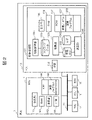
- FIG. 2 is a configuration diagram of a vehicle system included in the vehicle 1.
- the vehicle system is configured by connecting a communication unit 12, an ECU 13, an ECU 14, an ECU 15, an ECU 16 and the like on an in-vehicle network 11 (for example, a CAN network).
- an in-vehicle network 11 for example, a CAN network
- the ECU 13 collects the software update status of each ECU and also collects data items representing the status of the vehicle 1.
- the ECU 13 includes an interface unit 132 and a collection function unit 131.
- the interface unit 132 is a communication interface that communicates with another device via the in-vehicle network 11.
- the collection function unit 131 includes the following.
- the collection unit 1331 collects data on the in-vehicle network 11.
- the collection log 1332 is a collection of data collected by the collection unit 1331.
- the calculation unit 1341 processes and calculates the log collected by the collection unit 1331 based on a specific format and conditions.
- the log 1342 is a collection of calculation results by the calculation unit 1341, and is data to be transmitted to the data center 2.
- the output unit 135 outputs the log 1342 at a specific frequency and cycle, and the RAM (Random Access Memory) 136 temporarily stores the data.
- the non-volatile ROM (Read Only Memory) 137 stores programs and data even after the power of the ECU 13 is cut off.
- the non-volatile ROM 137 stores the collection program 1371 and the arithmetic program 1372.
- the collection program 1371 is a program that implements a collection method and a data output method.
- the arithmetic program 1372 is a program that implements data format conversion, arithmetic procedures, and the like.
- the configuration data 1382 (hereinafter abbreviated as config data 1382) describes an update state such as a software version of all ECUs in the vehicle 1.
- the diagnostic management unit 1381 collects config data 1382 from each ECU.
- the collected log, log, and config data are stored in a means for storing the data as non-volatile data so that the contents are retained even after the power of the ECU 13 is cut off, such as an SD card.
- the ECU 14 includes an interface unit 141 with the in-vehicle network 11, a calculation unit 142, a RAM 143, a non-volatile ROM 144, and a diagnostic unit 145.
- the non-volatile ROM 144 stores an arithmetic program 1441 that implements an application provided by the ECU 14.
- the diagnosis unit 145 aggregates failures and information in the ECU 14 and responds in response to a failure command.
- the diagnostic management unit 1381 also has the same function as the diagnostic unit 145.
- the ROM provided in each ECU shall be a double bank.
- the double bank is a mechanism in which two program areas are prepared, one surface is activated and used, the remaining one surface is rewritten by OTA, and then the effective surface is switched.
- the arithmetic programs 1372 and 1441 and the collection program 1371 are omitted in FIG. 2, but have a double bank configuration.
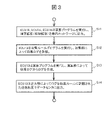
- FIG. 3 is a flowchart illustrating a procedure in which the ECU 13 collects data from each ECU.
- Each of the ECU 14, the ECU 15, and the ECU 16 executes an arithmetic program mounted on the ECU 14, and outputs the arithmetic result (processing result) to the in-vehicle network 11 (S11).
- the collection unit 1331 collects data on the in-vehicle network 11 by executing the collection program 1371 and accumulates the collection log 1332 (S12).
- the calculation unit 1341 executes the calculation program 1372 to perform format conversion and calculation on the collection log 1332, and generates the log 1342 (S13).
- the output unit 135 transmits the log 1342 to the data center 2 at the transmission frequency described in the collection rule (S14).
- Each of the ECUs 13 to 16 is provided with a calculation unit (calculation program).
- a calculation unit calculation program.
- the software in the vehicle 1 is centrally managed by the ECU 13.
- the config data 1382 is data that holds the centralized management information.
- FIG. 4 shows an example of config data 1382.
- FIG. 4 holds an ECU hard ID, a program ID, a CAN database number, a free CAN ID, and a free ROM capacity.
- CAN ID may be consumed by outputting new CAN data items depending on the function.
- the free ROM capacity consumed by updating the program also fluctuates. Therefore, in FIG. 4, it was decided to retain the free CANID and the free ROM capacity. Based on these data items, it is possible to determine whether or not a new program can be installed.
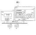
- FIG. 5 is a diagram illustrating a procedure for creating config data 1382.
- the diagnostic management unit 1381 includes a diagnostic CAN command map 1383 that describes diagnostic commands for inquiring the software update status to all ECUs (ECUs 14 to 16 in FIG. 5) in the vehicle 1.
- the diagnostic management unit 1381 sequentially issues diagnostic commands 1384 on the in-vehicle network 11 based on the diagnostic CAN command map 1383.
- the diagnosis unit 145 of the target ECU (for example, ECU 14) creates software configuration information as shown in FIG. 4 in the same manner as the failure information, and returns the software configuration information to the ECU 13 as a response to the diagnosis command 1384.
- the diagnostic management unit 1381 can similarly create config data 1382 by collecting software configuration information from all ECUs.
- the content of the diagnostic command may differ for each ECU, so it may be defined for each ECU.
- the destination information of each ECU may be described together with the diagnostic command.
- the diagnostic command does not necessarily have to be newly developed in order to implement the present invention, and a command for inquiring about the software version, free ROM space, etc. may be diverted in the existing failure diagnosis procedure.
- the conventional diagnostic command is for diagnosing each ECU individually
- the diagnostic command in the present invention is used not only for the conventional diagnosis but also for collecting config data 1382. Is different.
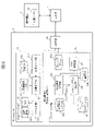
- FIG. 6 is a configuration diagram of the data center 2.
- the data center 2 includes a communication unit 25, a collection service unit 21, and an OTA service unit 23 that communicate with other devices via the base station 4.
- the collection service unit 21 specifies the requirements required by the function of collecting the data items based on the data collection items specified by the driver on the mobile phone 3.
- the collection service unit 21 includes a collection server unit 211, a customer database 212, a vehicle model function database 213, a collection requirement unit 214, a log analysis unit 215, and an analysis result 216.
- the customer database 212 manages the basic information of the customer (driver using the mobile phone 3 in FIG. 1) and the collection items set in the past.
- the vehicle type function database 213 holds a unique collection function ID for both the data items that can be collected as standard for each vehicle type and the data items that can be collected by expansion.
- the collection server unit 211 operates as a WEB server accessed by the collection application 31 of the mobile phone 3.
- the driver specifies the vehicle type of the vehicle 1 on the mobile phone 3 and inquires the data center 2 about the data items that can be collected.
- the collection server unit 211 refers to the vehicle type function database 213 in response to a request from the mobile phone 3 and responds with a list of data items that can be collected by the vehicle 1 as standard and data items that can be collected by expansion.
- the driver specifies the data items to be collected in the vehicle 1 on the mobile phone 3.
- the collection requirement unit 214 acquires a collection function ID capable of collecting data items specified by the driver from the vehicle model function database 213.
- the collection requirement unit 214 outputs the collection function ID to the OTA service unit 23 together with the customer ID and the vehicle model ID of the driver stored in the customer database 212.
- the log 22 is a collection of log data transferred from the vehicle.
- the log analysis unit 215 analyzes the log 22 and outputs the analysis result 216.
- the analysis result 216 can be passed to a service that requires customer analysis, such as a marketing service or a telematic insurance service, and the analysis result 216 can be utilized in those services.
- the OTA service department 23 distributes the updated version program to the vehicle 1.
- the OTA service unit 23 includes a collection request analysis unit 231, a config data 232, a vehicle ECU software database 233, an OTA program generation unit 234, an OTA program database 24, a customer database 236, and an OTA distribution unit 237.
- the config data 232 is the config data 1382 held by the vehicle 1 received from the vehicle 1.
- the vehicle ECU software database 233 holds data items that can be collected for each software version of each ECU included in the vehicle 1.
- the collection program 1371 retains collectable data items for each version of the collection program 1371.
- data items that can be output to the in-vehicle network 11 are stored for each version of the calculation program.
- the collection request analysis unit 231 identifies a function capable of collecting data items desired by the driver based on the collection function ID received from the collection service unit 21.
- the collection request analysis unit 231 can collect the data items desired by the driver based on the collection function ID and the program ID of each ECU held by the config data 232 (both the collection program 1371 and the calculation program). ),
- the program ID is acquired from the vehicle ECU software database 233.
- the collection request analysis unit 231 outputs the acquired ID of each program to the OTA program generation unit 234.
- the OTA program database 24 holds each version of the program (both the collection program 1371 and the arithmetic program). Each version of each program is uniquely identified by the program ID.
- the program is not necessarily a complete program, but may be a module or the like that implements a specific function or the like.
- the OTA program generation unit 234 acquires an updated version of each program by referring to the OTA program database 24 using the ID of the collection program 1371 and the ID of the arithmetic program of each ECU as the program ID, and updates the update.
- the version is used to generate a program to be delivered to vehicle 1 by OTA.
- the OTA program database 24 holds a program module, the program to be distributed to the vehicle 1 may be generated by combining the modules.
- the customer database 236 holds security information (for example, an electronic signature) for each driver.
- the OTA distribution unit 237 refers to the customer database 236, adds a security mechanism corresponding to the driver of the vehicle 1, and then distributes the program generated by the OTA program generation unit 234 to the vehicle 1.
- FIG. 7 is a flowchart illustrating a procedure in which the data center 2 updates the collection program 1371 and the arithmetic program. Each step of FIG. 7 will be described below.
- FIG. 7 Step S701
- the driver of the vehicle 1 uses the collection application 31 of the mobile phone 3 to specify data items to be collected by the vehicle 1. Collection conditions such as collection time intervals can also be specified.
- Collection conditions such as collection time intervals can also be specified.
- the data items and collection conditions are collectively referred to as collection conditions below.
- the collection server unit 211 acquires collection conditions from the mobile phone 3.
- the collection requirement unit 214 identifies a collection function ID capable of collecting the data item specified by the collection condition, and outputs the customer information and the collection function ID to the OTA service unit 23.
- Steps S703 to S704 The collection request analysis unit 231 identifies the vehicle 1 from the customer information and requests the vehicle 1 to transfer the config data 1382 to the data center 2 (S703).
- the collection function unit 131 transfers the latest config data 1382 in the vehicle 1 to the data center 2 (S704). As a result, the config data 1382 held by the vehicle 1 and the config data 232 held by the data center 2 match.
- the collection request analysis unit 231 acquires the program ID of the collection program 1371 and the program ID of the calculation program of each ECU from the vehicle ECU software database 233 based on the collection function ID and the config data 232.
- the collection request analysis unit 231 transmits these program IDs to the OTA program generation unit 234.
- the OTA program generation unit 234 creates a program (updated version of each program) to be distributed by OTA by referring to the OTA program database 24 based on the program ID of the collection program 1371 and the program ID of the arithmetic program of each ECU. ..
- the OTA program may be an all-area update or a differential update.
- Step S707 The OTA distribution unit 237 simultaneously distributes the updated version of the collection program 1371 and the calculation program of each ECU to the vehicle 1 by the OTA function.
- FIG. 7 Step S708
- Each ECU in the vehicle 1 updates its software by using the updated version program distributed by the OTA function.
- the collection function unit 131 updates the config data 1382.
- the diagnostic management unit 1381 periodically updates the config data 1382 separately from this step.
- Steps S709 to S710 The collection function unit 131 transmits the collected log to the collection server unit 211 (S709).
- the log analysis unit 215 analyzes the collected logs and accumulates the analysis results (S710).
- the ECU 13 collects config data 1382 that describes the update state of the program included in each ECU, and acquires an updated version program corresponding to each update state described in the config data 1382 from the data center 2. Then update the program with the updated program. Other ECUs also update the calculation program by the updated version program received from the same data center 2. Appropriate program updates are realized by managing software states such as software versions of all ECUs mounted on the vehicle 1 and free ROM space in the vehicle 1 and the data center 2 in a consistent manner. Further, when the software state of all the ECUs is collectively managed by the ECU 13, the calculation program of each ECU and the collection program 1371 of the ECU 13 can be generated in cooperation with each other.
- the ECU 13 issues a diagnostic command 1384 on the in-vehicle network 11 based on the diagnostic CAN command map 1383, and the ECU that receives the diagnostic command 1384 returns the software status as a response to this.
- the software state of each ECU can be aggregated as config data 1382 on the ECU 13.
- the collection program 1371 determines at least one of the frequency of collecting data from each ECU, the data items to be collected, and the frequency of transmitting the collected data to the data center 2. It is configured so that it can be changed for each version of. As a result, the user can freely customize the data collection process performed in the vehicle 1. For example, it is possible to cancel the function suppressed in the current ECU included in the vehicle 1 or add a new function, and then add a collection condition linked to the function. By customizing and acquiring the information of the vehicle 1, various information about the vehicle 1 can be utilized in an external service such as a telematics insurance service or a marketing service.
- an external service such as a telematics insurance service or a marketing service.
- the user of the vehicle 1 customizes the data collection items via the mobile phone 3, and the data center 2 can collect the customized data items. Is generated and transmitted to the vehicle 1.
- the user can freely customize the data items to be collected on the vehicle 1 while updating the calculation program of each ECU included in the vehicle 1 and the collection program 1371 in cooperation with each other.
- Collection program 1371 and calculation program on any one ECU (Update example 2) Collection program 1371 and calculation program on ECU 13 (Update example 3) Collection program 1371 (Update example 4) Collection program 1371 and calculation program on any two or more ECUs (a part of the ECU on vehicle 1)
- Each ECU can suppress the program update when the program cannot be updated, for example, when the free space of the ROM is insufficient.
- the vehicle 1 notifies the data center 2 to that effect.
- the OTA service unit 23 can notify the user of the mobile phone 3 to that effect via the collection service unit 21.
- the present invention is not limited to the above embodiment, and includes various modifications.
- the above-described embodiment has been described in detail in order to explain the present invention in an easy-to-understand manner, and is not necessarily limited to the one including all the described configurations.
- the collection program 1371 is updated for the ECU 13, and the calculation program is updated in conjunction with the other ECU (example: ECU 14).
- the format of the data items to be collected may be changed by updating the arithmetic programs of other ECUs, so it is necessary to change the processing such as format conversion by the arithmetic program 1372.
- the arithmetic program 1372 may be updated in conjunction with the collection program 1371 and each arithmetic program.
- the diagnostic management unit 1381 collects the config data 1382 from the ECU 14, and the collection unit 1331 and the collection program 1371 collect various data items (vehicle data) of the vehicle 1. May be aggregated as one program.
- one program may be implemented as the collection function unit 131, and the program may collect config data 1382 and vehicle data. That is, if the ECU 13 executes these processes, the division of roles between the programs may be arbitrary.
- the data item collected by the collection function unit 131 is not limited to the software state of the ECU included in the vehicle 1, and may be any data item representing the state of the vehicle 1.
- data representing the state of a device such as a sensor or an actuator controlled by the target ECU can be collected from the target ECU.
- information such as the traveling route of the vehicle 1 can be collected from the car navigation ECU, and information on the driver's preference can be collected from the infotainment ECU.
- At least one of the calculation program and the collection program 1371 may be different for each vehicle type (manufacturer, model number, etc.) of the vehicle 1.
- the data items and the like that can be collected for each vehicle type should be defined in the vehicle type function database 213, and the vehicle ECU software database 233 should be configured so that the program ID corresponding to the collection function ID differs for each vehicle type. Just do it.
- the data items that can be collected may differ depending on the vehicle type of the vehicle 1.
- constraints on data collection may be defined, such as data items that cannot be collected at the same time.
- This constraint condition may be defined in, for example, the vehicle type function database 213.
- the data center 2 when the data center 2 distributes the updated program of each ECU to the vehicle 1, the data center 2 may directly distribute the updated program to each ECU, or the data center 2 distributes only the destination ECU.
- the gateway device in the vehicle 1 may receive the updated version program of each ECU. In the latter case, the updated program will be distributed to each ECU via the gateway device.
- the ECU that collects various data of the vehicle 1 may be a control device that controls any function of the vehicle 1, and does not necessarily have a role of controlling the other ECUs. It does not have to be an ECU.
- each arithmetic function unit included in each ECU or data center 2 can be configured by hardware such as a circuit device that implements these functions, or software that implements these functions is used as an arithmetic unit. Can also be configured by executing. It can also be configured with a combination of hardware and software.
- the collection unit 1331, the calculation unit 1341, the diagnosis management unit 1381, the collection service unit 21, and the OTA service unit 23 can be configured by hardware, software, or a combination thereof.
- the functional unit that stores data eg, collection log 1332, log 1342, config data 1382, log 22, each DB
- Vehicle 11 In-vehicle network 12: TCU 13: ECU 131: Collection function unit 1331: Collection unit 1341: Calculation unit 135: Output unit 136: RAM 1371: Collection program 1372: Arithmetic program 1381: Diagnosis management unit 1382: Config data 14: ECU 142: Arithmetic unit 145: Diagnosis unit 1441: Arithmetic program 2: Data center 21: Collection service unit 22: Log 23: OTA service unit 24: OTA program database 3: Mobile phone 4: Base station
Landscapes
- Engineering & Computer Science (AREA)
- Theoretical Computer Science (AREA)
- General Engineering & Computer Science (AREA)
- Physics & Mathematics (AREA)
- General Physics & Mathematics (AREA)
- Software Systems (AREA)
- Computer Security & Cryptography (AREA)
- Health & Medical Sciences (AREA)
- Biomedical Technology (AREA)
- Quality & Reliability (AREA)
- Stored Programmes (AREA)
- Control Of Driving Devices And Active Controlling Of Vehicle (AREA)
Abstract
Description
本発明の実施形態1では、車両内のデータを収集し、センタにそのデータログをアップロードすることを想定する。本実施形態1に係る更新システムは、ECUアプリケーションにおいて必要な機能が不足する場合、データ収集プログラムとアプリケーションを連携して更新する手段を提供する。
車両1のドライバは、携帯電話3の収集アプリケーション31を用いて、車両1が収集すべきデータ項目を指定する。収集時間間隔などの収集条件を併せて指定することもできる。データ項目と収集条件を併せて以下では収集条件と呼ぶ。
収集サーバ部211は、携帯電話3から収集条件を取得する。収集要件部214は、収集条件が指定するデータ項目を収集することができる収集機能IDを特定し、顧客情報と収集機能IDをOTAサービス部23へ出力する。
収集要求分析部231は、顧客情報から車両1を特定し、コンフィグデータ1382をデータセンタ2へ転送するように車両1に対して要求する(S703)。収集機能部131は、車両1内の最新のコンフィグデータ1382をデータセンタ2に転送する(S704)。これにより、車両1が保持しているコンフィグデータ1382とデータセンタ2が保持しているコンフィグデータ232が一致する。
収集要求分析部231は、収集機能IDとコンフィグデータ232に基づき、収集プログラム1371のプログラムIDと、各ECUの演算プログラムのプログラムIDを、車両ECUソフトデータベース233から取得する。収集要求分析部231は、これらのプログラムIDをOTAプログラム生成部234に送信する。
OTAプログラム生成部234は、収集プログラム1371のプログラムIDと各ECUの演算プログラムのプログラムIDを元に、OTAプログラムデータベース24を参照することにより、OTA配信するプログラム(各プログラムの更新版)を作成する。OTAプログラムは全領域更新でもよいし、差分更新でもよい。
OTA配信部237は、収集プログラム1371と各ECUの演算プログラムそれぞれの更新バージョンを、OTA機能によって車両1へ同時配信する。
車両1内の各ECUは、OTA機能によって配信された更新版プログラムを用いてそれぞれのソフトウェアを更新する。収集機能部131は、コンフィグデータ1382を更新する。診断管理部1381は、本ステップとは別に、定期的にコンフィグデータ1382を更新する。
収集機能部131は、収集したログを収集サーバ部211に送信する(S709)。ログ分析部215は、収集したログを分析し、分析結果を蓄積する(S710)。
本実施形態1に係るECU13は、各ECUが備えるプログラムの更新状態を記述したコンフィグデータ1382を収集し、コンフィグデータ1382が記述している各更新状態に対応する更新版プログラムをデータセンタ2から取得してその更新版プログラムによってプログラムを更新する。その他のECUも同様のデータセンタ2から受け取った更新版プログラムによって演算プログラムを更新する。車両1が搭載する全ECUのソフトウェアバージョンやROM空き容量などのソフトウェア状態を、車両1とデータセンタ2それぞれにおいて一致させて管理することによって、適切なプログラム更新を実現している。さらに、全ECUのソフトウェア状態をECU13が統括的に管理することにより、各ECUの演算プログラムとECU13の収集プログラム1371を連携して生成することができる。
実施形態1において、各ECUの演算プログラムと収集プログラム1371を連携して更新することを説明した。これらは必ずしも同時に更新する必要はなく、以下のいずれかを更新してもよい。
(更新例2)収集プログラム1371とECU13上の演算プログラム
(更新例3)収集プログラム1371
(更新例4)収集プログラム1371といずれか2以上(車両1上のECUのうち一部)のECU上の演算プログラム
本発明は上記実施形態に限定されるものではなく、様々な変形例が含まれる。例えば、上記実施形態は本発明を分かりやすく説明するために詳細に説明したものであり、必ずしも説明した全ての構成を備えるものに限定されるものではない。また、ある実施形態の構成の一部を他の実施形態の構成に置き換えることが可能であり、また、ある実施形態の構成に他の実施形態の構成を加えることも可能である。また、各実施形態の構成の一部について、他の構成の追加・削除・置換をすることが可能である。
11:車内ネットワーク
12:TCU
13:ECU
131:収集機能部
1331:収集部
1341:演算部
135:出力部
136:RAM
1371:収集プログラム
1372:演算プログラム
1381:診断管理部
1382:コンフィグデータ
14:ECU
142:演算部
145:診断部
1441:演算プログラム
2:データセンタ
21:収集サービス部
22:ログ
23:OTAサービス部
24:OTAプログラムデータベース
3:携帯電話
4:基地局
Claims (12)
- 車両の動作を制御する車両制御装置であって、
前記車両制御装置が提供する機能を実装したプログラムを格納するプログラム記憶部、
前記プログラムを実行する演算部、
前記プログラムの更新状態を表すコンフィグレーションデータを格納するコンフィグレーションデータ記憶部、
を備え、
前記プログラム記憶部は、前記プログラムとして、
前記車両制御装置が提供する演算機能を実装した演算プログラム、
前記車両が搭載している第2車両制御装置から前記第2車両制御装置が実装している第2プログラムの更新状態を表す第2プログラム更新状態データを収集する処理を実装した収集プログラム、
を格納しており、
前記演算部は、前記コンフィグレーションデータと前記第2プログラム更新状態データを集約して、前記プログラムの更新版を配信するサーバに対して送信し、
前記演算部は、前記コンフィグレーションデータに対応する前記プログラムの更新版を前記サーバから受信し、
前記演算部は、前記サーバから受信した前記プログラムの更新版によって、前記プログラム記憶部が格納している前記プログラムを更新する
ことを特徴とする車両制御装置。 - 前記車両制御装置はさらに、前記第2車両制御装置が故障しているか否かを診断するために用いる診断コマンドと前記診断コマンドの宛先情報を記述した診断コマンドマップを備え、
前記収集プログラムは、前記診断コマンドマップにしたがって前記第2車両制御装置に対して前記診断コマンドを送信することにより前記第2プログラム更新状態データを要求するステップを、前記演算部に実行させ、
前記収集プログラムは、前記診断コマンドに対する応答を前記第2プログラム更新状態データとして前記コンフィグレーションデータへ集約するステップを、前記演算部に実行させる
ことを特徴とする請求項1記載の車両制御装置。 - 前記収集プログラムは、前記車両の状態を表す車両データを収集するステップを、前記演算部に実行させ、
前記収集プログラムは、前記収集した前記車両データを前記サーバに対して送信するステップを、前記演算部に実行させる
ことを特徴とする請求項1記載の車両制御装置。 - 前記収集プログラムは、前記車両データを収集する頻度、前記車両データとして収集する項目、および前記車両データを前記サーバに対して送信する頻度を実装しており、
前記演算部は、前記プログラムの更新版によって、前記収集プログラムのうち、前記車両データを収集する頻度、前記車両データとして収集する項目、または前記車両データを前記サーバに対して送信する頻度の少なくともいずれかを更新する
ことを特徴とする請求項3記載の車両制御装置。 - 請求項1記載の車両制御装置、
前記車両が搭載している第2車両制御装置、
を備え、
前記第2車両制御装置は、前記コンフィグレーションデータに対応する前記第2プログラムの更新版を前記サーバから受信し、
前記第2車両制御装置は、前記サーバから受信した前記第2プログラムの更新版によって、前記第2プログラムを更新する
ことを特徴とする車両システム。 - 前記収集プログラムは、前記車両の状態を表す車両データとして収集する項目を規定しており、
前記第2プログラムは、前記車両データを提供するステップを実装しており、
前記演算部は、前記プログラムの更新版によって、前記収集プログラムのうち、前記車両データとして収集する項目を更新し、
前記第2車両制御装置は、前記プログラムの更新版によって更新された前記項目を提供するステップを実装するように、前記第2プログラムの更新版によって前記第2プログラムを更新する
ことを特徴とする請求項5記載の車両システム。 - 車両が搭載している車両制御装置が実行するプログラムを更新する更新システムであって、
請求項5記載の車両システム、
前記プログラムの更新版を前記車両制御装置に対して送信するとともにと前記第2プログラムの更新版を前記第2車両制御装置に対して送信するサーバ、
を有することを特徴とする更新システム。 - 前記収集プログラムは、前記車両の状態を表す車両データを収集するステップを、前記演算部に実行させるように構成されており、
前記サーバは、前記車両データとして収集する項目を指定する項目リクエストをユーザ端末から受信し、
前記サーバは、前記項目リクエストが指定する項目を前記車両データとして収集するステップを実装した前記収集プログラムを、前記プログラムの更新版として前記車両制御装置に対して送信する
ことを特徴とする請求項7記載の更新システム。 - 前記サーバは、前記項目リクエストを受信すると、前記コンフィグレーションデータを送信するように要求するコンフィグレーションデータリクエストを前記車両制御装置に対して送信し、
前記サーバは、前記コンフィグレーションデータリクエストに応答して前記車両制御装置から受信した前記コンフィグレーションデータを用いて、前記プログラムの更新状態を特定し、
前記サーバは、前記特定した前記プログラムの更新状態と、前記項目リクエストが指定する項目とにしたがって、前記項目リクエストが指定する項目を前記車両データとして収集するステップを実装した前記収集プログラムを生成し、
前記サーバは、前記生成した前記収集プログラムを、前記プログラムの更新版として前記車両制御装置に対して送信する
ことを特徴とする請求項8記載の更新システム。 - 前記サーバは、前記コンフィグレーションデータリクエストに応答して前記車両制御装置から受信した前記コンフィグレーションデータを用いて、前記第2プログラムの更新状態を特定し、
前記サーバは、前記特定した前記第2プログラムの更新状態と、前記項目リクエストが指定する項目とにしたがって、前記項目リクエストが指定する項目を前記車両データとして提供するステップを実装した前記第2プログラムを生成し、
前記サーバは、前記生成した前記第2プログラムを、前記第2プログラムの更新版として前記第2車両制御装置に対して送信する
ことを特徴とする請求項9記載の更新システム。 - 前記サーバは、前記収集プログラムが収集することができる前記項目の組み合わせごとに前記収集プログラムの更新版を格納するデータベースを備え、
前記サーバは、前記項目リクエストが指定する前記項目を全て収集することができる前記収集プログラムの更新版を前記データベースから取得し、
前記サーバは、前記取得した前記収集プログラムの更新版を、前記プログラムの更新版として前記車両制御装置に対して送信する
ことを特徴とする請求項8記載の更新システム。 - 前記サーバは、前記プログラムの更新版と併せて、前記第2プログラムの更新版を前記第2車両制御装置に対して送信し、
前記第2車両制御装置は、前記受信した前記第2プログラムの更新版によって前記第2プログラムを更新することにより、前記車両制御装置における前記プログラムの更新と連動して、前記第2プログラムを更新する
ことを特徴とする請求項7記載の更新システム。
Priority Applications (2)
| Application Number | Priority Date | Filing Date | Title |
|---|---|---|---|
| DE112021005187.3T DE112021005187T5 (de) | 2021-01-12 | 2021-09-07 | Fahrzeugsteuervorrichtung, fahrzeugsystem und aktualisierungssystem |
| US18/253,790 US12585452B2 (en) | 2021-01-12 | 2021-09-07 | Vehicle control device, vehicle system and update system |
Applications Claiming Priority (2)
| Application Number | Priority Date | Filing Date | Title |
|---|---|---|---|
| JP2021-002608 | 2021-01-12 | ||
| JP2021002608A JP7550060B2 (ja) | 2021-01-12 | 2021-01-12 | 車両制御装置、車両システム、更新システム |
Publications (1)
| Publication Number | Publication Date |
|---|---|
| WO2022153591A1 true WO2022153591A1 (ja) | 2022-07-21 |
Family
ID=82447078
Family Applications (1)
| Application Number | Title | Priority Date | Filing Date |
|---|---|---|---|
| PCT/JP2021/032908 Ceased WO2022153591A1 (ja) | 2021-01-12 | 2021-09-07 | 車両制御装置、車両システム、更新システム |
Country Status (4)
| Country | Link |
|---|---|
| US (1) | US12585452B2 (ja) |
| JP (1) | JP7550060B2 (ja) |
| DE (1) | DE112021005187T5 (ja) |
| WO (1) | WO2022153591A1 (ja) |
Families Citing this family (3)
| Publication number | Priority date | Publication date | Assignee | Title |
|---|---|---|---|---|
| JPWO2024095632A1 (ja) * | 2022-11-02 | 2024-05-10 | ||
| CN121263783A (zh) | 2023-05-26 | 2026-01-02 | 日产自动车株式会社 | 电子控制装置和电子控制方法 |
| US12632329B1 (en) * | 2024-12-30 | 2026-05-19 | Harman Becker Automotive Systems, Inc. | Systems and methods for artificial intelligence-based analysis of over-the-air client logs |
Citations (4)
| Publication number | Priority date | Publication date | Assignee | Title |
|---|---|---|---|---|
| JP2010282385A (ja) * | 2009-06-04 | 2010-12-16 | Fujitsu Ten Ltd | 情報処理システム |
| JP2011148398A (ja) * | 2010-01-21 | 2011-08-04 | Denso Corp | 車両用プログラム更新システム |
| JP2019036251A (ja) * | 2017-08-21 | 2019-03-07 | 株式会社東芝 | 更新制御装置、ソフトウェア更新システムおよび更新制御方法 |
| WO2020111090A1 (ja) * | 2018-11-28 | 2020-06-04 | 株式会社オートネットワーク技術研究所 | 監視装置、監視プログラム及び監視方法 |
Family Cites Families (4)
| Publication number | Priority date | Publication date | Assignee | Title |
|---|---|---|---|---|
| KR101459493B1 (ko) * | 2013-10-08 | 2014-11-07 | 현대자동차 주식회사 | 차량 전자 제어 장치 및 차량 제어방법 |
| JP2018055191A (ja) | 2016-09-26 | 2018-04-05 | 株式会社日立製作所 | データ収集システム |
| US20190102158A1 (en) * | 2017-09-29 | 2019-04-04 | GM Global Technology Operations LLC | System and method for providing software updates in assembly line and dealership lot environments |
| DE102017220526A1 (de) * | 2017-11-17 | 2019-05-23 | Bayerische Motoren Werke Aktiengesellschaft | Verfahren und Vorrichtung zur Aktualisierung von Software |
-
2021
- 2021-01-12 JP JP2021002608A patent/JP7550060B2/ja active Active
- 2021-09-07 DE DE112021005187.3T patent/DE112021005187T5/de active Pending
- 2021-09-07 WO PCT/JP2021/032908 patent/WO2022153591A1/ja not_active Ceased
- 2021-09-07 US US18/253,790 patent/US12585452B2/en active Active
Patent Citations (4)
| Publication number | Priority date | Publication date | Assignee | Title |
|---|---|---|---|---|
| JP2010282385A (ja) * | 2009-06-04 | 2010-12-16 | Fujitsu Ten Ltd | 情報処理システム |
| JP2011148398A (ja) * | 2010-01-21 | 2011-08-04 | Denso Corp | 車両用プログラム更新システム |
| JP2019036251A (ja) * | 2017-08-21 | 2019-03-07 | 株式会社東芝 | 更新制御装置、ソフトウェア更新システムおよび更新制御方法 |
| WO2020111090A1 (ja) * | 2018-11-28 | 2020-06-04 | 株式会社オートネットワーク技術研究所 | 監視装置、監視プログラム及び監視方法 |
Also Published As
| Publication number | Publication date |
|---|---|
| JP7550060B2 (ja) | 2024-09-12 |
| JP2022107913A (ja) | 2022-07-25 |
| US20230418587A1 (en) | 2023-12-28 |
| US12585452B2 (en) | 2026-03-24 |
| DE112021005187T5 (de) | 2023-09-14 |
Similar Documents
| Publication | Publication Date | Title |
|---|---|---|
| EP3557849B1 (en) | Software management system and control method for software management system | |
| JP7550060B2 (ja) | 車両制御装置、車両システム、更新システム | |
| US10652335B2 (en) | Dynamically presenting vehicle sensor data via mobile gateway proximity network | |
| JP7571621B2 (ja) | センター装置及び車載電子制御装置 | |
| US8190322B2 (en) | Autonomous vehicle maintenance and repair system | |
| US20210397433A1 (en) | On-board update device, update processing program, program update method, and on-board update system | |
| JP7439720B2 (ja) | 更新データを配信するサーバ、方法及びプログラム | |
| US20210117177A1 (en) | On-board update device, update process method, and update process program | |
| JP2022020439A (ja) | サーバ、更新管理方法、更新管理プログラム、ソフトウェア更新装置、サーバ及びソフトウェア更新装置を備えるシステム | |
| CN106708988A (zh) | 一种城市轨道交通电子地图共享方法及系统 | |
| JP2019191742A (ja) | 車載更新装置、車載更新システム、更新処理方法及び更新処理プログラム | |
| US20250165246A1 (en) | Center, distribution control method, and non-transitory storage medium | |
| CA3069995A1 (en) | Configurable management system for a vehicle and method of use | |
| JP7677034B2 (ja) | 車両用のシステム、センタ、方法、及びプログラム | |
| CN112579121B (zh) | 一种数据处理的方法和装置 | |
| US8732286B2 (en) | Health management systems with shadow modules | |
| CN117714277B (zh) | 一种基于云原生的多集群网关及其工作方法 | |
| CN114840264A (zh) | 配置数据管理方法、配置数据管理装置和车辆管理系统 | |
| CN103688243B (zh) | 用于机动车的控制装置、编程装置和编程系统 | |
| JP7781007B2 (ja) | 情報処理方法、通信システムおよび情報処理プログラム | |
| JP7666194B2 (ja) | 車両用のシステム、センタ、方法、及びプログラム | |
| CN117827251A (zh) | 一种车辆ecu版本升级方法、系统及相关设备 | |
| WO2023223819A1 (ja) | 情報処理方法、通信システムおよび情報処理プログラム | |
| US20230052810A1 (en) | Control apparatus, control system, and method for determining function or operation of control apparatus | |
| CN118451733A (zh) | 车辆通信系统以及车载侧系统 |
Legal Events
| Date | Code | Title | Description |
|---|---|---|---|
| 121 | Ep: the epo has been informed by wipo that ep was designated in this application |
Ref document number: 21919483 Country of ref document: EP Kind code of ref document: A1 |
|
| WWE | Wipo information: entry into national phase |
Ref document number: 18253790 Country of ref document: US |
|
| WWE | Wipo information: entry into national phase |
Ref document number: 112021005187 Country of ref document: DE |
|
| 122 | Ep: pct application non-entry in european phase |
Ref document number: 21919483 Country of ref document: EP Kind code of ref document: A1 |
|
| WWG | Wipo information: grant in national office |
Ref document number: 18253790 Country of ref document: US |