WO2022153447A1 - 列車制御装置および空転滑走検知方法 - Google Patents
列車制御装置および空転滑走検知方法 Download PDFInfo
- Publication number
- WO2022153447A1 WO2022153447A1 PCT/JP2021/001078 JP2021001078W WO2022153447A1 WO 2022153447 A1 WO2022153447 A1 WO 2022153447A1 JP 2021001078 W JP2021001078 W JP 2021001078W WO 2022153447 A1 WO2022153447 A1 WO 2022153447A1
- Authority
- WO
- WIPO (PCT)
- Prior art keywords
- train
- pulse
- axle
- wheel
- control unit
- Prior art date
- Legal status (The legal status is an assumption and is not a legal conclusion. Google has not performed a legal analysis and makes no representation as to the accuracy of the status listed.)
- Ceased
Links
Images









Classifications
-
- B—PERFORMING OPERATIONS; TRANSPORTING
- B61—RAILWAYS
- B61L—GUIDING RAILWAY TRAFFIC; ENSURING THE SAFETY OF RAILWAY TRAFFIC
- B61L15/00—Indicators provided on the vehicle or train for signalling purposes
- B61L15/0058—On-board optimisation of vehicle or vehicle train operation
-
- B—PERFORMING OPERATIONS; TRANSPORTING
- B60—VEHICLES IN GENERAL
- B60L—PROPULSION OF ELECTRICALLY-PROPELLED VEHICLES; SUPPLYING ELECTRIC POWER FOR AUXILIARY EQUIPMENT OF ELECTRICALLY-PROPELLED VEHICLES; ELECTRODYNAMIC BRAKE SYSTEMS FOR VEHICLES IN GENERAL; MAGNETIC SUSPENSION OR LEVITATION FOR VEHICLES; MONITORING OPERATING VARIABLES OF ELECTRICALLY-PROPELLED VEHICLES; ELECTRIC SAFETY DEVICES FOR ELECTRICALLY-PROPELLED VEHICLES
- B60L3/00—Electric devices on electrically-propelled vehicles for safety purposes; Monitoring operating variables, e.g. speed, deceleration or energy consumption
- B60L3/10—Indicating wheel slip ; Correction of wheel slip
-
- B—PERFORMING OPERATIONS; TRANSPORTING
- B61—RAILWAYS
- B61L—GUIDING RAILWAY TRAFFIC; ENSURING THE SAFETY OF RAILWAY TRAFFIC
- B61L15/00—Indicators provided on the vehicle or train for signalling purposes
- B61L15/0094—Recorders on the vehicle
-
- Y—GENERAL TAGGING OF NEW TECHNOLOGICAL DEVELOPMENTS; GENERAL TAGGING OF CROSS-SECTIONAL TECHNOLOGIES SPANNING OVER SEVERAL SECTIONS OF THE IPC; TECHNICAL SUBJECTS COVERED BY FORMER USPC CROSS-REFERENCE ART COLLECTIONS [XRACs] AND DIGESTS
- Y02—TECHNOLOGIES OR APPLICATIONS FOR MITIGATION OR ADAPTATION AGAINST CLIMATE CHANGE
- Y02T—CLIMATE CHANGE MITIGATION TECHNOLOGIES RELATED TO TRANSPORTATION
- Y02T10/00—Road transport of goods or passengers
- Y02T10/60—Other road transportation technologies with climate change mitigation effect
- Y02T10/72—Electric energy management in electromobility
Definitions
- This disclosure relates to a train control device mounted on a train and a slip detection method.
- the on-board device calculates the speed from the speed pulses detected by the rotation detection devices installed on a plurality of axles, and the error of each speed based on the speed pulses detected by each rotation detection device is obtained.
- a technique for determining that slipping or sliding has occurred when the threshold is exceeded is disclosed.
- the present disclosure has been made in view of the above, and an object of the present disclosure is to obtain a train control device capable of accurately detecting slipping or slipping occurring in a train while suppressing a lengthening of the detection cycle.
- the present disclosure is a train control device mounted on a train in order to solve the above-mentioned problems and achieve the purpose.
- the train control device acquires the first pulse from the first speed sensor that detects the first pulse generated on the first axle of the train, and detects the second pulse generated on the second axle of the train.
- the train travels a specified distance among the acquisition unit that acquires the second pulse from the second speed sensor, the storage unit that stores the first pulse, and the second pulse, and the first pulse.
- the train slips or slides based on the pulse ratio of the first pulse number detected at the time and the second pulse number detected when the train travels a specified distance among the second pulses. It is characterized by including a control unit for determining the occurrence of the above.
- the train control device has an effect that it can accurately detect idling or sliding that occurs in a train while suppressing a lengthening of the detection cycle.
- a comparative example a diagram showing an example in which each measurement period for counting pulses detected by a speed sensor is independent.
- FIG. 4 is a fourth diagram showing a transition of a detection state of slipping or sliding on a train according to the first embodiment.
- a flowchart showing the operation of the train control device according to the first embodiment.
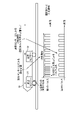
- FIG. 1 is a diagram schematically showing a configuration example of a train 10 on which the train control device 20 according to the first embodiment is mounted.
- the train 10 is composed of a vehicle 11 and a vehicle 12.
- the left side of the figure is the traveling direction of the train 10.
- the train 10 is a two-car train of vehicles 11 and 12, but this is an example and is not limited thereto.
- the train 10 on which the train control device 20 is mounted may be a 3-car train or more.
- the vehicle 11 includes a train control device 20, a speed sensor 31, axles 41 to 44, and wheels 51 to 54, 61 to 64.
- Wheels 51 and 61 are attached to the axle 41
- wheels 52 and 62 are attached to the axle 42
- wheels 53 and 63 are attached to the axle 43
- wheels 54 and 64 are attached to the axle 44.
- the speed sensor 31 detects the pulse generated on the axle 41.
- the speed sensor 31 may be referred to as a first speed sensor
- the axle 41 may be referred to as a first axle
- the pulse generated by the axle 41 detected by the speed sensor 31 may be referred to as a first pulse.
- the vehicle 12 includes a speed sensor 32, axles 45 to 48, and wheels 55 to 58, 65 to 68. Wheels 55 and 65 are attached to the axle 45, wheels 56 and 66 are attached to the axle 46, wheels 57 and 67 are attached to the axle 47, and wheels 58 and 68 are attached to the axle 48.
- the speed sensor 32 detects the pulse generated on the axle 47.
- the speed sensor 32 may be referred to as a second speed sensor
- the axle 47 may be referred to as a second axle
- the pulse generated on the axle 47 detected by the speed sensor 32 may be referred to as a second pulse.
- the train control device 20 is mounted on the train 10.
- the train control device 20 includes an acquisition unit 21, a storage unit 22, and a control unit 23.
- the acquisition unit 21 acquires the first pulse from the speed sensor 31 that detects the first pulse generated on the axle 41 of the train 10. Further, the acquisition unit 21 acquires the second pulse from the speed sensor 32 that detects the second pulse generated on the axle 47 of the train 10. The acquisition unit 21 stores the acquired first pulse and the second pulse in the storage unit 22.
- the storage unit 22 stores the first pulse and the second pulse acquired by the acquisition unit 21.
- the storage unit 22 stores the first pulse and the second pulse from the specified time.
- the storage unit 22 stores, for example, the first pulse and the second pulse acquired by the acquisition unit 21 after the train 10 starts operation on a certain day.
- the control unit 23 has the number of first pulses detected when the train 10 travels a specified distance among the first pulses stored in the storage unit 22, and the first pulse stored in the storage unit 22. Of the two pulses, the number of second pulses detected when the train 10 travels a specified distance is compared. The control unit 23 determines the occurrence of idling or sliding of the train 10 based on the pulse ratio which is the result of comparing the number of the first pulse and the number of the second pulse.
- the defined distance means the axle 41, which is the first axle to be detected by the speed sensor 31, and the axle 47, which is the second axle to be detected by the speed sensor 32, in the train 10. The distance between the axles.
- the control unit 23 of the train control device 20 has the first pulse number detected by the speed sensor 31 and the second pulse detected by the speed sensor 32 during the period in which the train 10 travels the distance between the axles as described above. Calculate the pulse ratio with the number. Further, it is assumed that the train control device 20 is held by the control unit 23 or the storage unit 22 with respect to the pulse ratio at the normal time when the train 10 does not slip or slide. The control unit 23 periodically calculates the pulse ratio while the train 10 is traveling, and compares the calculated pulse ratio with the normal pulse ratio.
- the control unit 23 determines that the train 10 has slipped or slipped when the difference is equal to or greater than the specified threshold value.
- the normal pulse ratio may be referred to as a normal pulse ratio.
- the train 10 slips or slides because there are foreign substances such as water, oil, and fallen leaves on the rails (not shown) in contact with the wheels 51 to 58 and 61 to 68 of the train 10, and the wheels 51 to 58, This is a case where the frictional force between 61 to 68 and the rail is weakened.
- idling or sliding in the train 10 occurs when the wheels 51 to 58 and 61 to 68 reach a specific position on the rail. Therefore, in the train 10, the speed sensors 31 and 32 are installed at ten distances.
- the train 10 even if the wheels 51 and 61 attached to the axle 41 to be detected by the speed sensor 31 in front of the traveling direction of the train 10 slip or slide, the train 10 moves in the traveling direction.
- the wheels 57 and 67 which are located behind and attached to the axle 47 to be detected by the speed sensor 32, are in a state where idling or sliding has not occurred.
- the wheels 51 and 61 will be referred to as front wheels
- the wheels 57 and 67 will be referred to as rear wheels.
- the axle 41 is fitted with front wheels, which are the front wheels 51, 61 of the train 10 in the traveling direction of the train 10, and the axle 47 has the rear wheels 57, of the train 10 in the traveling direction of the train 10.
- the rear wheel, which is 67, is attached.
- the control unit 23 of the train control device 20 increases the number of pulses on the axle 41 to which the front wheels are attached during the measurement period in which the number of pulses corresponding to the distance between the axles is generated from the current time on the axle 47 to which the rear wheels are attached. Always compare whether a pulse has occurred.
- the control unit 23 can determine whether or not the train 10 has slipped or slipped by comparing the pulse ratio, which is the result of the comparison, with the pulse ratio in the normal state.
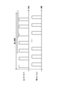
- FIG. 2 is a diagram showing an example of pulses detected by the speed sensors 31 and 32 when the train 10 according to the first embodiment does not slip or slide.
- the upper row shows the first pulse detected by the speed sensor 31, and the lower row shows the second pulse detected by the speed sensor 32.
- the horizontal axis represents time.
- the difference between the pulse ratio in the measurement period in which the number of pulses corresponding to the distance between the axles is generated from the current time on the axle 47 to which the rear wheels are attached and the specified normal pulse ratio is less than the threshold value. Shows the case.
- FIG. 2 schematically shows each pulse for the sake of simplicity, and the number of pulses detected in the actual measurement period will be larger. The same applies to the figures described below.
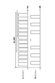
- FIG. 3 is a diagram showing an example of pulses detected by the speed sensors 31 and 32 when idling or sliding occurs in the train 10 according to the first embodiment.
- the upper row shows the first pulse detected by the speed sensor 31, and the lower row shows the second pulse detected by the speed sensor 32.
- the horizontal axis represents time.
- the difference between the pulse ratio in the measurement period in which the number of pulses corresponding to the distance between the axles is generated from the current time on the axle 47 to which the rear wheels are attached and the specified normal pulse ratio is equal to or greater than the threshold value. Shows the case.
- the control unit 23 can determine whether or not the train 10 has slipped or slipped by comparing the pulse ratio of each measurement period with the defined normal pulse ratio.
- the measurement period in which the control unit 23 detects the first pulse number and the second pulse number that is, the control unit 23 calculates the pulse ratio ends in one measurement period. It is assumed that a part of the measurement periods overlaps with each other in the preceding and following measurement periods, instead of starting the next measurement period later.
- the start timing of each measurement period is deviated by, for example, about 100 milliseconds or 200 milliseconds.
- This period of about 100 milliseconds or 200 milliseconds is the interval at which the control unit 23 calculates the pulse ratio in the measurement period, that is, confirms the pulse ratio. That is, the control unit 23 confirms the pulse ratio at intervals shorter than the period during which the train 10 travels the distance between the axles.
- the control unit 23 uses the pulses detected by the speed sensors 31 and 32 when the train 10 travels the inter-axle distance at intervals shorter than the measurement period during which the train 10 travels the inter-axle distance. It can be determined whether or not the train 10 has slipped or slipped.
- the control unit If the distance between the axles is sufficiently long with respect to the pulse interval at which the first pulse and the second pulse are detected, even if there is an error of one pulse in the number of pulses included in each measurement period, the control unit The error of the pulse ratio calculated in 23 becomes extremely small.
- FIG. 4 is a diagram showing an example of pulses detected by the speed sensors 31 and 32 when idling or sliding occurs for a short period of time on the train 10 according to the first embodiment.
- the upper row shows the first pulse detected by the speed sensor 31, and the lower row shows the second pulse detected by the speed sensor 32.
- the horizontal axis represents time.
- each measurement period for counting the pulses detected by the speed sensors 31 and 32 is independent as a comparative example.
- FIG. 5 assumes that each measurement period for counting the number of pulses is independent, that is, the next measurement period starts after the end of one measurement period.
- each measurement period is a period corresponding to the deviation amount of each measurement period shown in FIG. In such a case, even if a sudden pulse is detected as the first pulse in a certain measurement period, the sudden pulse is not detected in the next measurement period, so that it may be regarded as an erroneous detection of the speed sensor 31. There is.
- the control unit 23 can determine from the pulse ratios in the plurality of measurement periods that the train 10 has slipped or slipped even if the train 10 has slipped or slipped for a short period of time. .. As described above, when the number of times that the train 10 is continuously determined to have slipped or slipped is equal to or more than the specified number of times, the control unit 23 determines that the train 10 has actually slipped or slipped. When the number of times that the train 10 is continuously determined to have slipped or slipped is less than the specified number of times, the control unit 23 determines that the train 10 has not actually slipped or slipped.
- FIG. 6 is a first diagram showing the transition of the detection state of idling or sliding on the train 10 according to the first embodiment.
- FIG. 6 shows a state similar to that in the case of FIG. 2, and no idling or gliding is detected in either the first pulse of the speed sensor 31 or the second pulse of the speed sensor 32.
- FIG. 7 is a second diagram showing the transition of the detection state of idling or sliding on the train 10 according to the first embodiment.
- FIG. 7 shows a state in which wheels 51 and 61 attached to the axle 41 to be detected by the speed sensor 31 pass through a factor of idling or sliding, and pulse disturbance due to idling or sliding occurs in the first pulse of the speed sensor 31. Is shown.
- the wheels 57 and 67 attached to the axle 47 to be detected by the speed sensor 32 do not pass through the factors of idling or sliding, and thus are in the same state as in FIG.
- FIG. 8 is a third diagram showing the transition of the detection state of idling or sliding on the train 10 according to the first embodiment.
- the wheels 51 and 61 attached to the axle 41 to be detected by the speed sensor 31 pass through the factors of idling or sliding, and the speed sensor 31 It shows a state in which pulse turbulence due to idling or sliding occurs in the first pulse.
- the wheels 57 and 67 attached to the axle 47 to be detected by the speed sensor 32 do not pass through the factors of idling or sliding, and thus are in the same state as in FIG. FIG.
- FIG. 9 is a fourth diagram showing the transition of the detection state of idling or sliding on the train 10 according to the first embodiment.
- FIG. 9 shows a state in which the train 10 travels the distance between the axles after the wheels 51 and 61 attached to the axle 41 to be detected by the speed sensor 31 pass through the factors of idling or sliding, and the speed sensor 31 is the first. In one pulse, the disturbance of the pulse due to idling or sliding is eliminated.
- the wheels 57 and 67 attached to the axle 47 to be detected by the speed sensor 32 pass through the factors of idling or sliding, and the second pulse of the speed sensor 32 causes pulse turbulence due to idling or sliding. Indicates the state in which it occurred.
- the control unit 23 continuously detects the cause of slipping or sliding for a while after FIG. be able to. That is, even if the speed sensor 31 cannot detect idling or sliding, the control unit 23 can continuously detect idling or sliding using the speed sensor 32.
- the train control device 20 may hold a predetermined pulse ratio in advance in the control unit 23 or the storage unit 22, or the train 10 coasts without slipping or sliding. It may be calculated by the control unit 23 during operation and held by the control unit 23 or the storage unit 22. When the control unit 23 calculates the normal pulse ratio, the control unit 23 may periodically calculate and update the normal pulse ratio.
- FIG. 10 is a flowchart showing the operation of the train control device 20 according to the first embodiment.
- the acquisition unit 21 acquires the first pulse from the speed sensor 31 and acquires the second pulse from the speed sensor 32 (step S11).
- the acquisition unit 21 stores the acquired first pulse and the second pulse in the storage unit 22 (step S12).
- the control unit 23 reads out the number of the first pulse and the number of the second pulse included in the measurement period at the current time among the first pulse and the second pulse stored in the storage unit 22 (step S13). ..
- the control unit 23 calculates the pulse ratio using the number of read first pulses and the number of second pulses (step S14).
- the control unit 23 compares the calculated pulse ratio with the normal pulse ratio (step S15). When the difference between the calculated pulse ratio and the normal pulse ratio is less than the threshold value (step S15: Yes), the control unit 23 determines that the train 10 has not slipped or slipped (step S16). When the difference between the calculated pulse ratio and the normal pulse ratio is equal to or greater than the threshold value (step S15: No), the control unit 23 continuously makes the difference between the calculated pulse ratio and the normal pulse ratio equal to or greater than the threshold value. Count the number of times it has become (step S17). When the number of consecutive times exceeding the threshold value is less than the specified number of times (step S17: No), the control unit 23 determines that no idling or sliding has occurred in the train 10 (step S16).
- step S17 When the number of times that the threshold value is continuously exceeded is equal to or more than the specified number of times (step S17: Yes), the control unit 23 determines that the train 10 has slipped or slipped (step S18).
- the train control device 20 periodically performs the operation of the flowchart shown in FIG. 10 at intervals of the above-mentioned deviation amount of the measurement period, that is, about 100 milliseconds or 200 milliseconds.
- the acquisition unit 21 is an interface such as a communication device.
- the storage unit 22 is a memory.
- the control unit 23 is realized by a processing circuit.
- the processing circuit may be a processor and memory for executing a program stored in the memory, or may be dedicated hardware.
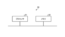
- FIG. 11 is a diagram showing an example in which the processing circuit 90 included in the train control device 20 according to the first embodiment is configured by the processor 91 and the memory 92.
- each function of the processing circuit 90 of the train control device 20 is realized by software, firmware, or a combination of software and firmware.
- the software or firmware is written as a program and stored in the memory 92.
- each function is realized by the processor 91 reading and executing the program stored in the memory 92. That is, the processing circuit 90 includes a memory 92 for storing a program in which the processing of the train control device 202 is eventually executed. It can also be said that these programs cause a computer to execute the procedures and methods of the train control device 20.
- the processor 91 may be a CPU (Central Processing Unit), a processing device, a computing device, a microprocessor, a microcomputer, a DSP (Digital Signal Processor), or the like.
- the memory 92 includes, for example, non-volatile or volatile such as RAM (Random Access Memory), ROM (Read Only Memory), flash memory, EPROM (Erasable Programmable ROM), and EPROM (registered trademark) (Electrically EPROM).
- RAM Random Access Memory
- ROM Read Only Memory
- flash memory EPROM (Erasable Programmable ROM), and EPROM (registered trademark) (Electrically EPROM).
- Semiconductor memory magnetic disk, flexible disk, optical disk, compact disk, mini disk, DVD (Digital Versatile Disc), etc. are applicable.
- FIG. 12 is a diagram showing an example in which the processing circuit 93 included in the train control device 20 according to the first embodiment is configured by dedicated hardware.
- the processing circuit 93 shown in FIG. 12 is, for example, a single circuit, a composite circuit, a programmed processor, a parallel programmed processor, or an ASIC (Application Specific Integrated Circuit). , FPGA (Field Programmable Gate Array), or a combination of these.
- Each function of the train control device 20 may be realized by the processing circuit 93 for each function, or each function may be collectively realized by the processing circuit 93.
- the functions of the train control device 20 may be realized by dedicated hardware, and some may be realized by software or firmware.
- the processing circuit can realize each of the above-mentioned functions by the dedicated hardware, software, firmware, or a combination thereof.
- the train control device 20 is used in the measurement period in which the train 10 travels the distance between the axles 41 and 47 targeted by the speed sensors 31 and 32 of the train 10. , The pulse ratio of the pulse detected by the speed sensors 31 and 32 was calculated, and it was decided whether or not the train 10 slipped or slipped by comparing with the pulse ratio at the normal time. As a result, the train control device 20 can accurately detect idling or sliding that occurs in the train 10 while suppressing the detection cycle from becoming long.
- Embodiment 2 In the second embodiment, a case where the control unit 23 of the train control device 20 corrects the wheel diameter of the wheels of the train 10 will be described.
- the configurations of the train 10 and the train control device 20 are the same as those of the first embodiment shown in FIG.
- the train control device 20 estimates the speed of the train 10, the mileage of the train 10, and the like by using the pulses acquired from the speed sensors 31 and 32 in the traveling control of the normal train 10.
- the wheels 51 and 61 attached to the axle 41 to be detected by the speed sensor 31 and the axle 47 to be detected by the speed sensor 32 are attached.
- Information on the wheel diameters of the wheels 57 and 67 is required.
- the wheels 51 to 58 and 61 to 68 of the train 10 are gradually scraped as the train 10 travels, and the wheel diameter becomes smaller.
- the control unit 23 of the train control device 20 assumes that one of the wheels has been scraped and the wheel diameter of the wheel. Is controlled to correct. For the sake of simplicity, it is assumed that the same type of wheels are used for the wheels 51 to 58 and 61 to 68 in the train 10.
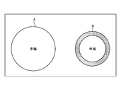
- FIG. 13 is a diagram showing an image of the wheel diameter of the wheels included in the train 10 according to the second embodiment.
- the wheels 51 and 61 attached to the axle 41 to be detected by the speed sensor 31 are referred to as wheels A
- the wheels 57 attached to the axle 47 to be detected by the speed sensor 32 Let 67 be the wheel B.
- the current initial wheel diameter of the wheel A is R_a
- the current initial wheel diameter of the wheel B is R_b
- the wheel diameter ratio between the initial wheel diameter R_a of the wheel A and the initial wheel diameter R_b of the wheel B is "R_a /”.
- R_b Diameter0 ”.
- the initial wheel diameter R_a is larger than the initial wheel diameter R_b, Radio 0> 1.
- FIG. 14 is a diagram showing an image in which the wheel B included in the train 10 according to the second embodiment is scraped. Since the wheel diameter does not increase unless it is replaced, the control unit 23 corrects the wheel diameter of the wheel B when Rio1> Ratio0.
- FIG. 15 is a diagram showing an image in which the wheel A included in the train 10 according to the second embodiment is scraped. Since the wheel diameter does not increase unless it is replaced, in the case of Rio1 ⁇ Ratio0, the control unit 23 corrects the wheel diameter of the wheel A.
- Ratio1 Ratio0
- the control unit 23 can also correct the wheel diameter more strictly.
- Ratio1> Ratio0 will be described as an example, but it can also be applied to the case of Ratio1 ⁇ Ratio0.
- the control unit 23 calculates the second new wheel diameter R_b 2 of the wheel B when the wheel A is maximally scraped with respect to the mileage of the train 10.
- the control unit 23 can estimate the speed, mileage, and the like of the train 10 by using the maximum wheel diameter R_b_max and the minimum wheel diameter R_b_min. Since the control unit 23 determines the detection of slipping or sliding of the first embodiment by the number of pulses detected on each wheel, even if the error of each wheel diameter becomes large, it has an influence. You can do it without receiving it.
- the control unit 23 divides the first wheel diameter of the first wheel attached to the first axle by the second wheel diameter of the second wheel attached to the second axle.
- the diameter ratio is calculated as a value obtained by dividing the number of second pulses by the number of first pulses and compared periodically.
- the control unit 23 determines that the second wheel has been scraped and corrects the second wheel diameter.
- the control unit 23 determines that the first wheel has been scraped and corrects the first wheel diameter.
- the control unit 23 estimates the speed of the train 10 and the mileage of the train 10 by using the first wheel diameter and the second wheel diameter.
- FIG. 16 is a flowchart showing the operation of the train control device 20 according to the second embodiment.
- the control unit 23 calculates the latest wheel diameter ratio (step S21).
- the control unit 23 compares whether or not the latest calculated wheel diameter ratio is larger than the previously calculated wheel diameter ratio (step S22).
- the control unit 23 corrects the wheel diameter of the wheel B (step S23).
- the control unit 23 compares whether or not the latest calculated wheel diameter ratio is smaller than the previously calculated wheel diameter ratio. (Step S24).
- step S24: Yes When the latest wheel diameter ratio is smaller than the previously calculated wheel diameter ratio (step S24: Yes), the control unit 23 corrects the wheel diameter of the wheel A (step S25). When the latest wheel diameter ratio is not smaller than the wheel diameter ratio calculated last time (step S24: No), the control unit 23 determines that the latest wheel diameter ratio is the same as the wheel diameter ratio calculated last time, and that the wheel A and the wheel B have the latest wheel diameter ratio. Neither wheel diameter is corrected (step S26), and the operation ends.
- the train control device 20 corrects the wheel diameter when it detects that the wheels A and B of the train 10 have been scraped. As a result, the train control device 20 can accurately estimate the speed of the train 10, the mileage of the train 10, and the like by using the corrected wheel diameter.
- the configuration shown in the above embodiments is an example, and can be combined with another known technique, can be combined with each other, and does not deviate from the gist. It is also possible to omit or change a part of the configuration.
Landscapes
- Engineering & Computer Science (AREA)
- Mechanical Engineering (AREA)
- Life Sciences & Earth Sciences (AREA)
- Sustainable Development (AREA)
- Sustainable Energy (AREA)
- Power Engineering (AREA)
- Transportation (AREA)
- Electric Propulsion And Braking For Vehicles (AREA)
Abstract
Description
図1は、実施の形態1に係る列車制御装置20が搭載される列車10の構成例を模式的に示す図である。列車10は、車両11および車両12によって構成される。図1の例では、矢印70が示すように、図の左側を列車10の進行方向とする。図1において、列車10が車両11,12の2両編成であるが、一例であり、これに限定されない。列車制御装置20が搭載される列車10は、3両編成以上であってもよい。
実施の形態2では、列車制御装置20の制御部23が、列車10の車輪の車輪径を補正する場合について説明する。
Claims (14)
- 列車に搭載される列車制御装置であって、
前記列車の第1の車軸で発生する第1のパルスを検出する第1の速度センサーから前記第1のパルスを取得し、前記列車の第2の車軸で発生する第2のパルスを検出する第2の速度センサーから前記第2のパルスを取得する取得部と、
前記第1のパルス、および前記第2のパルスを記憶する記憶部と、
前記第1のパルスのうち前記列車が規定された距離を走行する際に検出された第1のパルス数と、前記第2のパルスのうち前記列車が規定された前記距離を走行する際に検出された第2のパルス数とのパルス比率に基づいて、前記列車の空転または滑走の発生を判定する制御部と、
を備えることを特徴とする列車制御装置。 - 前記距離は、前記列車における前記第1の車軸と前記第2の車軸との間の車軸間距離である、
ことを特徴とする請求項1に記載の列車制御装置。 - 前記第1の車軸には、前記列車において前記列車の進行方向に対して前方の車輪である前輪が取り付けられ、前記第2の車軸には、前記列車において前記列車の進行方向に対して後方の車輪である後輪が取り付けられている、
ことを特徴とする請求項1または2に記載の列車制御装置。 - 前記制御部が前記第1のパルス数および前記第2のパルス数を検出する測定期間は、前後の複数の測定期間で一部の期間が重複しており、
前記制御部は、各測定期間の開始タイミングのずれ量の間隔で、前記パルス比率を確認する、
ことを特徴とする請求項1から3のいずれか1つに記載の列車制御装置。 - 前記制御部は、前記パルス比率と正常時パルス比率との差異が閾値未満の場合、前記列車において空転または滑走が発生していないと判定し、前記パルス比率と前記正常時パルス比率との差異が閾値以上の場合、前記列車において空転または滑走が発生していないと判定する、
ことを特徴とする請求項1から4のいずれか1つに記載の列車制御装置。 - 前記制御部は、前記列車の空転または滑走が発生したと連続して判定した回数が規定された回数以上の場合、前記列車で空転または滑走が実際に発生したと判定し、前記列車の空転または滑走が発生したと連続して判定した回数が前記規定された回数未満の場合、前記列車で空転または滑走が実際には発生していないと判定する、
ことを特徴とする請求項5に記載の列車制御装置。 - 前記制御部は、前記第1の車軸に取り付けられた第1の車輪の第1の車輪径を前記第2の車軸に取り付けられた第2の車輪の第2の車輪径で除算した車輪径比率を、前記第2のパルス数を前記第1のパルス数で除算した値として算出して定期的に比較し、前記車輪径比率が前回よりも大きくなった場合、前記第2の車輪が削れたと判定して前記第2の車輪径を補正し、前記車輪径比率が前回よりも小さくなった場合、前記第1の車輪が削れたと判定して前記第1の車輪径を補正する、
ことを特徴とする請求項1から6のいずれか1つに記載の列車制御装置。 - 列車に搭載される列車制御装置の空転滑走検知方法であって、
取得部が、前記列車の第1の車軸で発生する第1のパルスを検出する第1の速度センサーから前記第1のパルスを取得し、前記列車の第2の車軸で発生する第2のパルスを検出する第2の速度センサーから前記第2のパルスを取得する第1のステップと、
前記取得部が、前記第1のパルス、および前記第2のパルスを記憶部に記憶させる第2のステップと、
制御部が、前記第1のパルスのうち前記列車が規定された距離を走行する際に検出された第1のパルス数と、前記第2のパルスのうち前記列車が規定された前記距離を走行する際に検出された第2のパルス数とのパルス比率に基づいて、前記列車の空転または滑走の発生を判定する第3のステップと、
を含むことを特徴とする空転滑走検知方法。 - 前記距離は、前記列車における前記第1の車軸と前記第2の車軸との間の車軸間距離である、
ことを特徴とする請求項8に記載の空転滑走検知方法。 - 前記第1の車軸には、前記列車において前記列車の進行方向に対して前方の車輪である前輪が取り付けられ、前記第2の車軸には、前記列車において前記列車の進行方向に対して後方の車輪である後輪が取り付けられている、
ことを特徴とする請求項8または9に記載の空転滑走検知方法。 - 前記制御部が前記第1のパルス数および前記第2のパルス数を検出する測定期間は、前後の複数の測定期間で一部の期間が重複しており、
前記第3のステップにおいて、前記制御部は、各測定期間の開始タイミングのずれ量の間隔で、前記パルス比率を確認する、
ことを特徴とする請求項8から10のいずれか1つに記載の空転滑走検知方法。 - 前記第3のステップにおいて、前記制御部は、前記パルス比率と正常時パルス比率との差異が閾値未満の場合、前記列車において空転または滑走が発生していないと判定し、前記パルス比率と前記正常時パルス比率との差異が閾値以上の場合、前記列車において空転または滑走が発生していないと判定する、
ことを特徴とする請求項8から11のいずれか1つに記載の空転滑走検知方法。 - 前記第3のステップにおいて、前記制御部は、前記列車の空転または滑走が発生したと連続して判定した回数が規定された回数以上の場合、前記列車で空転または滑走が実際に発生したと判定し、前記列車の空転または滑走が発生したと連続して判定した回数が前記規定された回数未満の場合、前記列車で空転または滑走が実際には発生していないと判定する、
ことを特徴とする請求項12に記載の空転滑走検知方法。 - さらに、
前記制御部が、前記第1の車軸に取り付けられた第1の車輪の第1の車輪径を前記第2の車軸に取り付けられた第2の車輪の第2の車輪径で除算した車輪径比率を、前記第2のパルス数を前記第1のパルス数で除算した値として算出して定期的に比較し、前記車輪径比率が前回よりも大きくなった場合、前記第2の車輪が削れたと判定して前記第2の車輪径を補正し、前記車輪径比率が前回よりも小さくなった場合、前記第1の車輪が削れたと判定して前記第1の車輪径を補正する第4のステップ、
を含むことを特徴とする請求項8から13のいずれか1つに記載の空転滑走検知方法。
Priority Applications (4)
| Application Number | Priority Date | Filing Date | Title |
|---|---|---|---|
| US18/260,358 US20240067239A1 (en) | 2021-01-14 | 2021-01-14 | Train control device and slip-slide detection method |
| DE112021006801.6T DE112021006801T5 (de) | 2021-01-14 | 2021-01-14 | Zugsteuerungseinrichtung und schlupf-gleit-detektionsverfahren |
| PCT/JP2021/001078 WO2022153447A1 (ja) | 2021-01-14 | 2021-01-14 | 列車制御装置および空転滑走検知方法 |
| JP2022574958A JP7301246B2 (ja) | 2021-01-14 | 2021-01-14 | 列車制御装置および空転滑走検知方法 |
Applications Claiming Priority (1)
| Application Number | Priority Date | Filing Date | Title |
|---|---|---|---|
| PCT/JP2021/001078 WO2022153447A1 (ja) | 2021-01-14 | 2021-01-14 | 列車制御装置および空転滑走検知方法 |
Publications (1)
| Publication Number | Publication Date |
|---|---|
| WO2022153447A1 true WO2022153447A1 (ja) | 2022-07-21 |
Family
ID=82448086
Family Applications (1)
| Application Number | Title | Priority Date | Filing Date |
|---|---|---|---|
| PCT/JP2021/001078 Ceased WO2022153447A1 (ja) | 2021-01-14 | 2021-01-14 | 列車制御装置および空転滑走検知方法 |
Country Status (4)
| Country | Link |
|---|---|
| US (1) | US20240067239A1 (ja) |
| JP (1) | JP7301246B2 (ja) |
| DE (1) | DE112021006801T5 (ja) |
| WO (1) | WO2022153447A1 (ja) |
Families Citing this family (1)
| Publication number | Priority date | Publication date | Assignee | Title |
|---|---|---|---|---|
| US12454293B2 (en) * | 2022-10-17 | 2025-10-28 | Siemens Mobility, Inc | System and method for automatic wheel diameter measurement and calibration |
Citations (4)
| Publication number | Priority date | Publication date | Assignee | Title |
|---|---|---|---|---|
| JPS6277803A (ja) * | 1985-09-30 | 1987-04-10 | Toshiba Corp | 車両用速度検知装置 |
| JP2008086085A (ja) * | 2006-09-26 | 2008-04-10 | Toshiba Corp | 電気車制御装置 |
| JP2015037329A (ja) * | 2013-08-09 | 2015-02-23 | 日本信号株式会社 | 列車制御装置 |
| JP2019204364A (ja) * | 2018-05-24 | 2019-11-28 | アイシン精機株式会社 | 周辺監視装置 |
Family Cites Families (1)
| Publication number | Priority date | Publication date | Assignee | Title |
|---|---|---|---|---|
| CN109153333B (zh) * | 2016-05-12 | 2022-05-31 | 株式会社京三制作所 | 车载装置和列车占用范围计算方法 |
-
2021
- 2021-01-14 US US18/260,358 patent/US20240067239A1/en not_active Abandoned
- 2021-01-14 WO PCT/JP2021/001078 patent/WO2022153447A1/ja not_active Ceased
- 2021-01-14 JP JP2022574958A patent/JP7301246B2/ja active Active
- 2021-01-14 DE DE112021006801.6T patent/DE112021006801T5/de active Pending
Patent Citations (4)
| Publication number | Priority date | Publication date | Assignee | Title |
|---|---|---|---|---|
| JPS6277803A (ja) * | 1985-09-30 | 1987-04-10 | Toshiba Corp | 車両用速度検知装置 |
| JP2008086085A (ja) * | 2006-09-26 | 2008-04-10 | Toshiba Corp | 電気車制御装置 |
| JP2015037329A (ja) * | 2013-08-09 | 2015-02-23 | 日本信号株式会社 | 列車制御装置 |
| JP2019204364A (ja) * | 2018-05-24 | 2019-11-28 | アイシン精機株式会社 | 周辺監視装置 |
Also Published As
| Publication number | Publication date |
|---|---|
| JP7301246B2 (ja) | 2023-06-30 |
| JPWO2022153447A1 (ja) | 2022-07-21 |
| DE112021006801T5 (de) | 2023-11-30 |
| US20240067239A1 (en) | 2024-02-29 |
Similar Documents
| Publication | Publication Date | Title |
|---|---|---|
| US20100030428A1 (en) | Method and device for determining an absolute value of a variable | |
| JP2002500761A (ja) | 車両タイヤの圧力低下検出方法 | |
| WO2018155489A1 (ja) | 車両制御装置、車両制御方法、プログラム | |
| CN111886170A (zh) | 车辆控制装置 | |
| JP6838655B2 (ja) | 車両制御装置 | |
| WO2022153447A1 (ja) | 列車制御装置および空転滑走検知方法 | |
| JPWO2015008786A1 (ja) | 車両制御装置 | |
| JP2004148910A (ja) | 空気圧低下の検知装置およびこれを用いて行われるセンサの補正方法 | |
| JP6971688B2 (ja) | 定位置停止制御装置及び位置算出装置 | |
| JP6925904B2 (ja) | 車両速度位置検知装置、車両運転支援装置、車両運転制御装置、方法及びプログラム | |
| JP5039149B2 (ja) | ロールレートセンサの信号のオフセットを求めるための方法と装置 | |
| CN112776540B (zh) | 用于检测胎压的装置和方法 | |
| JP7166432B2 (ja) | 列車制御装置および列車制御システム | |
| JP4660842B2 (ja) | 振子制御式鉄道車両の車輪径自動補正方法 | |
| JPH07229754A (ja) | 電気車の走行距離演算装置 | |
| JPWO2022153447A5 (ja) | ||
| JP6324001B2 (ja) | 車上装置 | |
| JP2002510037A (ja) | 車輪速度の補正値を決定する方法と装置 | |
| JP7789286B2 (ja) | 走行距離算出装置および走行距離算出方法 | |
| JP2000168552A (ja) | 鉄道車両の走行位置検知方法 | |
| JP5640127B1 (ja) | 車上装置 | |
| KR101150209B1 (ko) | 차량의 종 가속도 오프셋 보정 방법 | |
| ES3053867T3 (en) | Method for controlling wheel deformation, associated device and system including such a device | |
| JP3959135B2 (ja) | 車輪懸架装置調整システム | |
| JPWO2024262021A5 (ja) |
Legal Events
| Date | Code | Title | Description |
|---|---|---|---|
| 121 | Ep: the epo has been informed by wipo that ep was designated in this application |
Ref document number: 21919341 Country of ref document: EP Kind code of ref document: A1 |
|
| ENP | Entry into the national phase |
Ref document number: 2022574958 Country of ref document: JP Kind code of ref document: A |
|
| WWE | Wipo information: entry into national phase |
Ref document number: 202327044952 Country of ref document: IN |
|
| WWE | Wipo information: entry into national phase |
Ref document number: 18260358 Country of ref document: US |
|
| WWE | Wipo information: entry into national phase |
Ref document number: 112021006801 Country of ref document: DE |
|
| 122 | Ep: pct application non-entry in european phase |
Ref document number: 21919341 Country of ref document: EP Kind code of ref document: A1 |