WO2022149205A1 - 映像表示モジュール着脱治具 - Google Patents
映像表示モジュール着脱治具 Download PDFInfo
- Publication number
- WO2022149205A1 WO2022149205A1 PCT/JP2021/000181 JP2021000181W WO2022149205A1 WO 2022149205 A1 WO2022149205 A1 WO 2022149205A1 JP 2021000181 W JP2021000181 W JP 2021000181W WO 2022149205 A1 WO2022149205 A1 WO 2022149205A1
- Authority
- WO
- WIPO (PCT)
- Prior art keywords
- display module
- image display
- cover
- video display
- detachment jig
- Prior art date
- Legal status (The legal status is an assumption and is not a legal conclusion. Google has not performed a legal analysis and makes no representation as to the accuracy of the status listed.)
- Ceased
Links
Images










Classifications
-
- G—PHYSICS
- G09—EDUCATION; CRYPTOGRAPHY; DISPLAY; ADVERTISING; SEALS
- G09F—DISPLAYING; ADVERTISING; SIGNS; LABELS OR NAME-PLATES; SEALS
- G09F9/00—Indicating arrangements for variable information in which the information is built-up on a support by selection or combination of individual elements
-
- G—PHYSICS
- G09—EDUCATION; CRYPTOGRAPHY; DISPLAY; ADVERTISING; SEALS
- G09F—DISPLAYING; ADVERTISING; SIGNS; LABELS OR NAME-PLATES; SEALS
- G09F9/00—Indicating arrangements for variable information in which the information is built-up on a support by selection or combination of individual elements
- G09F9/30—Indicating arrangements for variable information in which the information is built-up on a support by selection or combination of individual elements in which the desired character or characters are formed by combining individual elements
- G09F9/33—Indicating arrangements for variable information in which the information is built-up on a support by selection or combination of individual elements in which the desired character or characters are formed by combining individual elements being semiconductor devices, e.g. diodes
-
- G—PHYSICS
- G09—EDUCATION; CRYPTOGRAPHY; DISPLAY; ADVERTISING; SEALS
- G09F—DISPLAYING; ADVERTISING; SIGNS; LABELS OR NAME-PLATES; SEALS
- G09F9/00—Indicating arrangements for variable information in which the information is built-up on a support by selection or combination of individual elements
- G09F9/40—Indicating arrangements for variable information in which the information is built-up on a support by selection or combination of individual elements in which the desired character is selected from a number of characters arranged one beside the other, e.g. on a common carrier plate
Definitions
- the present disclosure relates to a video display module attachment / detachment jig for attaching / detaching an image display module from an image display device constituting a large screen.
- the multi-display system which consists of a large screen with a video display device in which multiple LED display elements such as LEDs (Light Emitting Diodes) are arranged, is available outdoors and indoors thanks to the technological development and cost reduction of the LED display elements. It is often used for displaying advertisements in.
- multi-display systems equipped with this video display device have been mainly used for displaying moving images of natural images and animations.
- the viewing distance becomes shorter as the pixel pitch becomes narrower. Therefore, a multi-display system equipped with a video display device is used for displaying personal computer screens in conference rooms and surveillance applications. It is also used in. Especially in surveillance applications, personal computer screens that are close to still images are often displayed.
- an LED display element is mounted inside a cavity molded of ceramic or resin, and a small LED display module molded by solidifying this with a sealing resin is used as a substrate.
- the SMD (Surface Mount Device: surface mount component) type mounted on the mainstream is the mainstream.
- An image display device equipped with an SMD type LED display element has been used as a large-scale multi-display system having a pixel pitch of 3 mm or more.
- the uniformity of the flat surface of the image display surface greatly affects the image quality. Therefore, the method of holding and fixing the image display module is important, and the work of attaching and detaching the image display module at the time of installation and service is frequently performed.
- Patent Documents 1 and 2 disclose a method of holding and adjusting a video display module which is a component of a video display device.
- a attachment / detachment jig having a suction force stronger than the holding force is used when attaching / detaching the image display module.
- the attachment / detachment jig is brought close to the image display module, the image display module is suddenly drawn to the attachment / detachment jig.
- a strong force is momentarily required when removing the attachment / detachment jig from the image display module. Therefore, there is a risk of damaging the video display module when the video display module is attached or detached.
- the attachment / detachment jig described in Patent Document 2 is provided with an electromagnet, and can control the magnetic attraction generated between the image display module and the attachment / detachment jig by reducing or turning off the power supplied to the electromagnet.
- an electromagnet In order to supply electric power to the electromagnet, it is necessary to equip the attachment / detachment jig body with a battery or connect the attachment / detachment jig to an external power source. As a result, the size of the attachment / detachment jig becomes large, and it is difficult to handle the image display module. As described above, with the conventional technique, it has not been possible to easily attach / detach the video display module.
- an object of the present disclosure is to provide a video display module attachment / detachment jig that can easily attach / detach the image display module from the image display device constituting the large screen.
- the video display module attachment / detachment jig is a video display module attachment / detachment jig for attaching / detaching the image display module from an image display device constituting a large screen by fixing a plurality of image display modules to a housing.
- the image display module attachment / detachment jig includes a case, a cover, a magnet, and a handle.
- the case has a contact portion that abuts on the front surface of the image display module.
- the cover was attached to the case so as to be openable and closable around the axis of rotation.
- the magnet is provided at a position opposite to the contact portion of the case in the cover, and forms a magnetic coupling with the magnetic material provided in the image display module.
- the handle was provided on the cover. The distance between the magnet and the magnetic body is adjusted by opening and closing the cover in conjunction with the operation of the handle.
- the distance between the magnet and the magnetic material can be adjusted by operating the handle, it is possible to control the magnetic coupling between the image display module and the image display module attachment / detachment jig. can. This eliminates the need for a strong force when removing the video display module attachment / detachment jig from the video display module.
- the magnetic coupling between the video display module and the video display module attachment / detachment jig can be controlled by operating the handle, a battery or an external device for supplying power to the video display module attachment / detachment jig can be controlled. No power supply is required. As a result, the video display module attachment / detachment jig does not become large, and the video display module can be easily handled. From the above, the video display module can be easily attached to and detached from the video display device constituting the large screen.
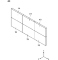
- FIG. 1 It is a perspective view which shows the schematic structure of the multi-display system which concerns on Embodiment 1.
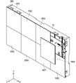
- FIG. It is a perspective view which shows the schematic structure of the image display apparatus included in the multi-display system which concerns on Embodiment 1.
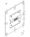
- FIG. It is a rear perspective view which shows the schematic structure of the image display module provided in the image display device.
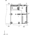
- It is a front view which shows the structure of the inside of a video display device in a state where a video display module is removed.
- FIG. 1 It is a perspective view which shows the state which the cover of the image display module attachment / detachment jig which concerns on Embodiment 1 is closed.
- FIG. 1 shows the schematic structure of the multi-display system which concerns on Embodiment 1.
- FIG. It is a perspective view which shows the schematic structure of the image display apparatus included in the multi-display system which concerns on Em
- FIG. 7 is a cross-sectional view taken along the line BB of FIG. It is a perspective view which shows the state which the cover of the image display module attachment / detachment jig which concerns on Embodiment 1 is open.
- 9 is a cross-sectional view taken along the line CC of FIG. It is sectional drawing which shows the state which attached the image display module attachment / detachment jig at the time of removing an image display module from an image display device. It is an enlarged view of the area D of FIG. It is sectional drawing which shows the state at the time of attaching / detaching the image display module attachment / detachment jig from an image display device. It is an enlarged view of the area E of FIG.
- FIG. 3 is a perspective view showing a closed state of the image display module attachment / detachment jig according to the third embodiment, as viewed from another direction.
- FIG. 19 is a sectional view taken along line GG of FIG.
- FIG. 3 is a perspective view showing a state in which the cover of the image display module attachment / detachment jig according to the third embodiment is held in a closed state. It is a perspective view which showed the state which held the state which the cover of the image display module attachment / detachment jig which concerns on Embodiment 3 was closed, and was seen from another direction.
- FIG. 2 is a sectional view taken along line JJ of FIG. 23. It is an enlarged view of the area K of FIG. 24.
- FIG. 1 is a perspective view showing a schematic configuration of the multi-display system 200 according to the first embodiment. Note that FIG. 1 shows the coordinate axes of the XYZ Cartesian coordinate system for ease of explanation.
- the X direction, the Y direction, and the Z direction are orthogonal to each other.
- the X, Y, and Z directions shown in the figure below are also orthogonal to each other.
- the direction including the X direction and the direction opposite to the X direction (-X direction) is also referred to as "X-axis direction”.
- the direction including the Y direction and the direction opposite to the Y direction ( ⁇ Y direction) is also referred to as “Y-axis direction”.
- the direction including the Z direction and the direction opposite to the Z direction ( ⁇ Z direction) is also referred to as “Z axis direction”.
- a plane including the X-axis direction and the Y-axis direction is also referred to as an “XY plane”.
- a plane including the X-axis direction and the Z-axis direction is also referred to as an “XZ plane”.
- a plane including the Y-axis direction and the Z-axis direction is also referred to as a “YZ plane”.
- the multi-display system 200 includes a plurality of image display devices 101 to 106 arranged in a matrix.
- the video display devices 101 to 106 are not distinguished, they are referred to as the video display device 100.
- the multi-display system 200 is a digital signage used for displaying advertisements outdoors and indoors, or a display for displaying a personal computer screen for a conference room and a monitoring application.
- the multi-display system 200 is configured by combining a plurality of video display devices 100 fixed by fixed parts (not shown), and it is possible to display an image on a large screen in which the display screens of the plurality of video display devices 100 are combined. It has become.
- the multi-display system 200 is composed of six video display devices 100, but the number is not necessarily limited to six, and any number of them may be used.
- FIG. 2 is a perspective view showing a schematic configuration of an image display device 100 included in the multi-display system 200.
- the image display device 100 includes image display modules 1001 to 1008 in which a plurality of LEDs are arranged, and a housing 10.
- the housing 10 is a frame that holds a plurality of video display modules 1001 to 1008.
- the video display module 1000 is described.
- the video display device 100 is composed of eight video display modules 1000, but is not necessarily limited to eight, and may be configured by any number.
- FIG. 3 is a rear perspective view showing a schematic configuration of the image display module 1000 included in the image display device 100.
- the image display module 1000 includes a connector 2, a plate 3, and eight magnet adsorbents 4 on the back side of an LED substrate 1 on which a plurality of LEDs are mounted.
- the plate 3 is made of a magnetic material and is fixed to the central portion of the back surface of the LED substrate 1.
- the connector 2 projects in the ⁇ Z direction from the central portion of the plate 3.
- the eight magnet adsorbents 4 are fixed along the peripheral edge of the back surface of the LED substrate 1.
- FIG. 4 is a front view showing the internal configuration of the video display device 100 with the video display module 1004 removed.
- the housing 10 is provided with a plurality of magnets 11 and a power supply board 20.
- the power supply board 20 is provided with a connector 22 that is paired with the connector 2 of the video display module 1000.
- each of the power supply board 20 and the video display module 1000 is provided with a signal line and a power line (not shown).
- the signal line includes, for example, a video signal line and a control signal line.
- the connector 2 of the video display module 1000 is provided with a plurality of terminals electrically connected to the signal line, the power line, and the GND line on the power supply board 20.
- FIG. 5 is a cross-sectional view of the image display device 100.
- FIG. 6 is an enlarged view of the region A of FIG.
- eight magnets 11 are provided at positions of the housing 10 facing the image display module 1000.
- the image display module 1000 is held in the housing 10 by the attractive force 60 generated by the magnetic coupling between the magnet attracting body 4 provided in the image display module 1000 and the magnet 11 provided in the housing 10. Since the magnet adsorbent 4 forms a magnetic coupling with the magnet 11, the magnet adsorbent 4 is a magnetic material.
- FIG. 5 eight magnets 11 and a magnet adsorbent 4 are used for one image display module 1000 to form a magnetic coupling, but the number of magnets 11 and magnet adsorbents 4 used is a magnet. It can be changed to, for example, four or six depending on the attractive force between the 11 and the magnet adsorbent 4.
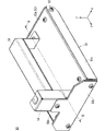
- FIG. 7 is a perspective view showing a state in which the cover 53 of the image display module attachment / detachment jig 50 is closed.
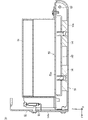
- FIG. 8 is a cross-sectional view taken along the line BB of FIG.
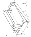
- FIG. 9 is a perspective view showing a state in which the cover 53 of the image display module attachment / detachment jig 50 is opened.
- FIG. 10 is a sectional view taken along line CC of FIG.
- the image display module attachment / detachment jig 50 includes a case 51, a plate 52, a cover 53, a magnet 54, a handle 55, and a spring 56.
- the case 51 has a bottom portion 51a having a plane parallel to the XY plane, a side portion 51b erected from the + Y side end of the bottom portion 51a, a side portion 51c erected from the + X side end of the bottom portion 51a, and a ⁇ of the bottom portion 51a. It is provided with a side portion 51d erected from the X side end.
- the plane parallel to the XY plane of the bottom portion 51a is a contact portion that abuts on the front surface of the image display module 1000.
- the portion of the bottom portion 51a on the ⁇ Y side of the contact portion is formed in an arc shape extending in the + Z direction.
- the plate 52 has a shape extending in the + Z direction and is fixed to the side portion 51b of the case 51.
- the plate 52 functions as a guide for the operator to put his / her hand on when the operator pulls the handle 55.
- the cover 53 is arranged at the + X side end of the flat plate-shaped upper plate portion 53a arranged on the + Z side, the concave lower plate portion 53b arranged on the ⁇ Z side, and the upper plate portion 53a and the lower plate portion 53b. It is composed of a side plate portion 53c (see FIG. 9) and a side plate portion 53d (see FIG. 9) arranged at the ⁇ X side end of the upper plate portion 53a and the lower plate portion 53b.
- the cover 53 is attached to the case 51 so as to be openable and closable around the rotation shaft 57.
- the rotation shaft 57 is provided at the ⁇ Y side end of the side portions 51b, 51c of the case 51, and is inserted through the side portions 51b, 51c of the case 51 and the side plate portions 53c, 53d of the cover 53.
- Two magnets 54 are provided side by side in the Y-axis direction at positions opposite to each other with the contact portion of the case 51 of the cover 53 interposed therebetween. Specifically, the two magnets 54 are screwed to the ⁇ Z side surface of the lower plate portion 53b of the cover 53. The two magnets 54 form a magnetic coupling with the plate 3 provided on the image display module 1000 in a state where the image display module attachment / detachment jig 50 is in contact with the front surface of the image display module 1000.
- the handle 55 is provided on the cover 53. Specifically, one end of the handle 55 is fixed to the ⁇ Y side end of the upper plate portion 53a of the cover 53, and the other end of the handle 55 is fixed to the + Y side end of the upper plate portion 53a of the cover 53.
- the cover is fixed to the ⁇ Y side end of the upper plate portion 53a of the cover 53.
- the spring 56 connects the plate 52 and the handle 55 with a tension that allows the cover 53 to be opened and closed, and urges the handle 55 in the direction in which the cover 53 closes.
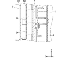
- FIG. 11 is a cross-sectional view showing a state in which the image display module attachment / detachment jig 50 is attached when the image display module 1000 is removed from the image display device 100.
- FIG. 12 is an enlarged view of the region D of FIG.
- the video display module 1000 can be removed from the housing 10 by pulling out the video display module attachment / detachment jig 50 in the + Z direction.
- the magnitude of the force for pulling the image display module attachment / detachment jig 50 is F50
- F50 satisfies Equation 2.
- the image display module 1000 can be removed from the housing 10 with the cover 53 open.
- the plate 3 forms a magnetic coupling with two magnets 54 provided in the image display module attachment / detachment jig 50, but the number of magnets 54 is, for example, depending on the attractive force. It can be changed to one or four.
- the image display device 100 in which the plurality of image display modules 1000 are arranged is arranged at the pixel pitch of the LED display element (for example, 1 mm or more and 2 mm or less), and the image display module 1000 is arranged at the time of assembly or maintenance. If the handling of the above is incorrect, the LED display element of another adjacent image display module 1000 or its peripheral members may come into contact with each other and be damaged.
- the distance between the magnet 54 provided on the image display module attachment / detachment jig 50 and the plate 3 provided on the image display module 1000 can be adjusted.
- the image display module attachment / detachment jig 50 is brought closer to the image display module 1000 or removed from the image display module 1000 by increasing the distance between the magnet 54 and the plate 3, the image display module 1000 with respect to the housing 10 is used. It is possible to reduce the adsorption force 61 while maintaining the holding strength of the module. Therefore, the handling of the video display module 1000 becomes easy, and problems such as damage to the video display module 1000 can be solved.
- FIG. 13 is a cross-sectional view showing a state when the image display module attachment / detachment jig 50 is attached / detached from the image display device 100.
- FIG. 14 is an enlarged view of the region E of FIG.
- the image display module attachment / detachment jig 50 When removing the image display module attachment / detachment jig 50 from the image display module 1000, if the handle 55 is pulled in the + Z direction and the cover 53 is opened, the gap between the magnet 54 and the plate 3 becomes large and the suction force 61 becomes small. Become. At this time, when the image display module attachment / detachment jig 50 is pulled away in the + Z direction, the image display module 1000 displays an image while being fixed to the housing 10 by the attraction force 60 generated between the magnet 11 and the magnet adsorbent 4. The module attachment / detachment jig 50 can be removed from the image display module 1000.
- the image display module attachment / detachment jig 50 opens / closes with respect to the case 51 having a contact portion abutting on the front surface of the image display module 1000 and the case 51 centering on the rotating shaft 57.
- a magnet 54 to be formed and a handle 55 provided on the cover 53 are provided, and the distance between the magnet 54 and the plate 3 is adjusted by opening and closing the cover 53 in conjunction with an operation on the handle 55.
- the magnetic coupling between the image display module 1000 and the image display module attachment / detachment jig 50 can be controlled by operating the handle 55, power is supplied to the image display module attachment / detachment jig 50. No battery or external power supply is required. As a result, the image display module attachment / detachment jig 50 does not become large, so that the image display module 1000 can be easily handled. From the above, the video display module 1000 can be easily attached to and detached from the video display device 100 constituting the large screen.
- the magnet 54 and the plate 3 are separated from each other, and with the handle 55 pulled down and the cover 53 closed, the magnet 54 and the plate 3 are close to each other.
- the operator can easily visually distinguish the strength of the attractive force between the magnet 54 and the plate 3 based on the position of the handle 55.
- the operator mistakenly brings the image display module attachment / detachment jig 50 closer to the image display module 1000 in a state where the suction force is strong, and the image display module attachment / detachment jig 50 is suddenly attracted to the image display module 1000. It is possible to prevent the image display module 1000 from being damaged.
- the image display module attachment / detachment jig 50 further includes a spring 56 having one end connected to the handle 55 and the other end connected to the case 51, and the spring 56 urges the handle 55 in the direction in which the cover 53 closes. do.
- the case 51 comes into surface contact with the video display module 1000. As described above, since the case 51 does not come into contact with the image display module 1000 at a point, it is possible to prevent the image display module 1000 from being damaged without exerting a large force on a part of the image display module 1000.
- FIG. 15 is a perspective view showing a state in which the cover 53 of the image display module attachment / detachment jig 50A according to the second embodiment is closed.
- FIG. 16 is a perspective view showing a state in which the cover 53 of the image display module attachment / detachment jig 50A is opened.
- FIG. 17 is an enlarged view of the region F of FIG.
- the same components as those described in the first embodiment are designated by the same reference numerals, and the description thereof will be omitted.
- the video display module attachment / detachment jig 50 when the video display module attachment / detachment jig 50 is brought close to the video display module 1000 or removed from the video display module 1000, the work is performed with the cover 53 open, so that the work is performed during the work.
- the person needs to keep pulling the handle 55. If the force for pulling the handle 55 becomes insufficient and the cover 53 returns to the closed state vigorously due to the urging force of the spring 56, the image display module 1000 may be impacted and damaged.
- the image display module attachment / detachment jig 50A fixes the rotation position of the rotation shaft 57 with the cover 53 open.
- a fixing screw 58 is further provided.
- the fixing screw 58 is provided on the inner surface side of the arc-shaped extending portion of the bottom portion 51a of the case 51.
- the rotating shaft 57 is provided with a groove 57a to which the tip of the fixing screw 58 can be engaged.
- the fixing screw 58 is tightened with the cover 53 open, and the tip of the fixing screw 58 engages with the groove 57a of the rotating shaft 57, whereby the rotational position of the rotating shaft 57 is fixed.
- the tip of the fixing screw 58 is a portion of the fixing screw 58 that protrudes toward the rotating shaft 57.
- the rotating shaft 57 When the tip of the fixing screw 58 is not engaged with the groove 57a of the rotating shaft 57, the rotating shaft 57 is not fixed, and the operator pulls the handle 55 in the + Z direction to close the cover 53. It changes to the open state.
- the tip of the fixing screw 58 engages with the groove 57a of the rotating shaft 57 while the cover 53 is open, the rotation of the rotating shaft 57 is hindered and the cover 53 is held in the open state.
- the fixing screw 58 is loosened and the tip of the fixing screw 58 is disengaged from the groove 57a of the rotating shaft 57, the cover 53 returns to the closed state by the urging force of the spring 56.
- the rotary shaft 57 is inserted into the case 51 and the cover 53, and the image display module attachment / detachment jig 50A fixes the rotary position of the rotary shaft 57 with the cover 53 open.
- a fixing screw 58 is further provided.
- the cover 53 can be held in an open state, when the video display module attachment / detachment jig 50A is brought close to the video display module 1000 or removed from the video display module 1000, the operator holds the handle 55 during the work. You don't have to keep pulling. This reduces the burden on the operator and enables easy and safe handling of the video display module 1000.
- FIG. 18 is a perspective view showing a state in which the cover 53 of the image display module attachment / detachment jig 50B according to the third embodiment is closed.
- FIG. 19 is a perspective view showing a state in which the cover 53 of the image display module attachment / detachment jig 50B is closed, as viewed from another direction.
- FIG. 20 is a sectional view taken along line GG of FIG. 21 is an enlarged view of the region H of FIG. 20.
- FIG. 22 is a perspective view showing a state in which the cover 53 of the image display module attachment / detachment jig 50B is held in a closed state.
- FIG. 23 is a perspective view showing a state in which the cover 53 of the image display module attachment / detachment jig 50B is held in a closed state, as viewed from another direction.
- FIG. 24 is a sectional view taken along line JJ of FIG. 23.
- FIG. 25 is an enlarged view of the region K in FIG. 24.
- the same components as those described in the first and second embodiments are designated by the same reference numerals and the description thereof will be omitted.
- the magnitude of the suction force 61 satisfies Equation 1, but as the suction force 61 increases, the force for pulling the handle 55 increases in order to change the cover 53 from the closed state to the open state. The burden on the worker increases. Further, since the video display module 1000 is easily attracted to the video display module attachment / detachment jig 50, there is a high possibility that the video display module 1000 will be damaged. Therefore, it is desirable that the adsorption force 61 be reduced within the range that satisfies Equation 1.
- the force for pulling the image display module attachment / detachment jig 50 when the image display module 1000 is removed from the housing 10 by using the image display module attachment / detachment jig 50 becomes the expression 2.
- the image display module attachment / detachment jig 50 may be pulled with a force larger than the suction force 61. Since the case 51 and the cover 53 are connected only by the rotating shaft 57, when the force for pulling the image display module attachment / detachment jig 50 is larger than the suction force 61, only the cover 53 to which the handle 55 is fixed is pulled. , The cover 53 changes to the open state. Since the suction force 61 is small when the cover 53 is open, the image display module attachment / detachment jig 50 may be separated from the image display module 1000, and the image display module 1000 may be damaged.
- the video display module attachment / detachment jig 50B has a groove 70 provided in the case 51. Further includes a holder 71 fixed to the cover 53, a pin 72 provided in the holder 71 and engageable with the groove 70, and a spring 73 mounted on the pin 72. As shown in FIG. 22, the pin 72 engages with the groove 70 in a state where the cover 53 is closed, so that the cover 53 can be held in the closed state.
- the pin 72 is attached to the holder 71 with the holder 71 inserted.
- the pin 72 includes a shaft portion 72a that functions as a rotation axis of the pin 72 and a protruding portion 72b that protrudes in the direction perpendicular to the shaft portion 72a, and the shaft portion 72a and the protruding portion 72b form a T-shape. ..
- the holder 71 has a rectangular cuboid shape, and a groove 71a extending in the X-axis direction and extending from the middle portion to the + Y side surface is formed on the + Z side surface of the holder 71.
- the pin 72 can rotate about the X-axis direction with the shaft portion 72a as the rotation axis.
- the spring 73 mounted on the pin 72 urges the pin 72 so that the protruding portion 72b of the pin 72 faces in the + Z direction and the shaft portion 72a of the pin 72 is located in the + X direction.
- An L-shaped groove 70 is formed in the side portion 51b of the case 51.
- the groove 71a and the groove 70 have a width that allows the protrusion 72b of the pin 72 to pass through as the pin 72 rotates.
- the pin 72 is slid in the ⁇ X direction and is positively oriented around the X-axis direction along the groove 71a formed in the holder 71. As shown in FIGS. 22 to 25, the pin 72 slides in the + X direction due to the urging force of the spring 73. At this time, since the protruding portion 72b is engaged with the groove 70 formed in the side portion 51b of the case 51, the protruding portion 72b is held in a state of facing the + Y direction.
- the positive direction means a counterclockwise direction when viewed from the + X direction to the ⁇ X direction.
- the pin 72 With the protrusion 72b facing in the + Y direction, the pin 72 is slid in the ⁇ X direction and rotated in the opposite direction around the X-axis direction along the groove 71a formed in the holder 71, and the pin 72 is spring 73. It slides in the + X direction due to the urging force of the pin 72, and the pin 72 is held again in the state of facing the + Z direction.
- the reverse direction means a clockwise direction when viewed from the + X direction to the ⁇ X direction.
- the cover 53 can be changed between the closed state and the open state by operating the handle 55. be.
- the image display module attachment / detachment jig 50B is provided in the groove 70 provided in the case 51, the holder 71 fixed to the cover 53, and is provided in the holder 71 and is engaged with the groove 70. Further provided with a compatible pin 72, the pin 72 engages the groove 70 with the cover 53 closed.
- the cover 53 is also used when the video display module attachment / detachment jig 50B is pulled with a force larger than the suction force 61. Since the image display module attachment / detachment jig 50B does not change to the open state, it is possible to prevent the image display module attachment / detachment jig 50B from separating from the image display module 1000. As a result, the image display module 1000 can be safely removed from the housing 10 with a small suction force 61, and damage to the image display module 1000 can be suppressed.
Landscapes
- Physics & Mathematics (AREA)
- General Physics & Mathematics (AREA)
- Engineering & Computer Science (AREA)
- Theoretical Computer Science (AREA)
- Devices For Indicating Variable Information By Combining Individual Elements (AREA)
Abstract
大画面を構成する映像表示装置から映像表示モジュールの着脱を容易に行うことが可能な映像表示モジュール着脱治具を提供することを目的とする。映像表示モジュール着脱治具(50)は、ケース(51)と、カバー(53)と、磁石(54)と、ハンドル(55)とを備える。ケース(51)は、映像表示モジュール(1000)の前面に当接する当接部を有する。カバー(53)は、回転軸(57)を中心にケース(51)に対して開閉可能に取り付けられた。磁石(54)は、カバー(53)におけるケース(51)の当接部を挟んで反対側の位置に設けられ、かつ、映像表示モジュール(1000)に設けられた磁性体であるプレート(3)と磁気カップリングを形成する。ハンドル(55)は、カバー(53)に設けられた。ハンドル(55)に対する操作に連動してカバー(53)が開閉することで磁石(54)とプレート(3)との距離を調整する。
Description
本開示は、大画面を構成する映像表示装置から映像表示モジュールを着脱する映像表示モジュール着脱治具に関するものである。
LED(Light Emitting Diode:発光ダイオード)などのLED表示素子を複数配置した映像表示装置にて大画面を構成したマルチディスプレイシステムは、LED表示素子の技術発展と低コスト化のおかげで、屋外および屋内の広告表示等に多く使用されている。この映像表示装置を備えるマルチディスプレイシステムは、これまで自然画およびアニメーションの動画像の表示に用いられることが主流であった。しかし、屋内の広告表示等に使用される場合、画素ピッチの狭ピッチ化に伴い視認距離が短くなることから、映像表示装置を備えるマルチディスプレイシステムは、会議室および監視用途などのパソコン画面表示用にも使用されている。特に監視用途においては、静止画に近いパソコン画面を表示することが多くなっている。
また、映像表示装置を備えるマルチディスプレイシステムとしては、セラミックまたは樹脂などで成形されたキャビティの内部にLED表示素子を実装し、これと封止樹脂で固めることで成形された小さなLED表示モジュールを基板に実装したSMD(Surface Mount Device:表面実装部品)型が主流である。SMD型のLED表示素子を備えた映像表示装置は、これまで画素ピッチが3mm以上の大型マルチディスプレイシステムとして使用されてきた。
しかし、近年では、LED表示素子の低コスト化と高精細化を背景に、画素ピッチが1mm以上2mm以下等の高密度実装品にて構成されたLED表示素子を配置した映像表示装置をマトリクス状に並べて構成した大型マルチディスプレイシステムが市場に導入されている。
大型マルチディスプレイシステムにおいて、映像表示面の平面の均一性が映像品質に大きく影響する。そのため、映像表示モジュールの保持方法および固定方法が肝要であるとともに、設置時およびサービス時に映像表示モジュールを着脱する作業が頻繁に実施される。
例えば、特許文献1,2には、映像表示装置の構成要素である映像表示モジュールの保持方法および調整方法が開示されている。
特許文献1に記載の映像表示装置では、映像表示モジュールの着脱時に、保持力よりも強い吸着力を持つ着脱治具が用いられる。このような場合、映像表示モジュールに着脱治具を近づけると、映像表示モジュールが着脱治具に急に引き寄せられる。または、映像表示モジュールから着脱治具を取り外すときに瞬間的に強い力が必要になる。そのため、映像表示モジュールの着脱時に映像表示モジュールを破損させる恐れがあった。
特許文献2に記載の着脱治具は、電磁石を備え、電磁石への供給電力を低減またはオフすることで映像表示モジュールと着脱治具との間に発生する磁気吸着力の制御が可能である。しかし、電磁石に電力を供給するために着脱治具本体にバッテリーを備える、または着脱治具を外部電源に接続する必要がある。その結果、着脱治具が大型化するため、映像表示モジュールのハンドリングが困難である。このように、従来の技術では、映像表示モジュールの着脱を容易に行うことはできなかった。
そこで、本開示は、大画面を構成する映像表示装置から映像表示モジュールの着脱を容易に行うことが可能な映像表示モジュール着脱治具を提供することを目的とする。
本開示に係る映像表示モジュール着脱治具は、筐体に複数の映像表示モジュールを固定し大画面を構成する映像表示装置から前記映像表示モジュールを着脱する映像表示モジュール着脱治具である。映像表示モジュール着脱治具は、ケースと、カバーと、磁石と、ハンドルとを備える。ケースは、前記映像表示モジュールの前面に当接する当接部を有する。カバーは、回転軸を中心に前記ケースに対して開閉可能に取り付けられた。磁石は、前記カバーにおける前記ケースの前記当接部を挟んで反対側の位置に設けられ、かつ、前記映像表示モジュールに設けられた磁性体と磁気カップリングを形成する。ハンドルは、前記カバーに設けられた。前記ハンドルに対する操作に連動して前記カバーが開閉することで前記磁石と前記磁性体との距離を調整するものである。
本開示によれば、ハンドルに対する操作を行うことで磁石と磁性体との距離を調整することができるため、映像表示モジュールと映像表示モジュール着脱治具との間の磁気カップリングを制御することができる。これにより、映像表示モジュールから映像表示モジュール着脱治具を取り外すときに強い力は不要となる。
さらに、ハンドルに対する操作を行うことで映像表示モジュールと映像表示モジュール着脱治具との間の磁気カップリングを制御することができるため、映像表示モジュール着脱治具に電力を供給するためのバッテリーまたは外部電源は不要となる。これにより、映像表示モジュール着脱治具が大型化しないため、映像表示モジュールのハンドリングは容易である。以上より、大画面を構成する映像表示装置から映像表示モジュールの着脱を容易に行うことができる。
この開示の目的、特徴、局面、および利点は、以下の詳細な説明と添付図面とによって、より明白となる。
<実施の形態1>
(マルチディスプレイシステムの構成)
実施の形態1について、図面を用いて以下に説明する。図1は、実施の形態1に係るマルチディスプレイシステム200の概略構成を示す斜視図である。なお、図1には、説明を容易にするために、XYZ直交座標系の座標軸が示されている。
(マルチディスプレイシステムの構成)
実施の形態1について、図面を用いて以下に説明する。図1は、実施の形態1に係るマルチディスプレイシステム200の概略構成を示す斜視図である。なお、図1には、説明を容易にするために、XYZ直交座標系の座標軸が示されている。
図1において、X方向、Y方向およびZ方向は、互いに直交する。以下の図に示されるX方向、Y方向およびZ方向も、互いに直交する。以下においては、X方向と、当該X方向の反対の方向(-X方向)とを含む方向を「X軸方向」ともいう。また、以下においては、Y方向と、当該Y方向の反対の方向(-Y方向)とを含む方向を「Y軸方向」ともいう。また、以下においては、Z方向と、当該Z方向の反対の方向(-Z方向)とを含む方向を「Z軸方向」ともいう。
また、以下においては、X軸方向およびY軸方向を含む平面を、「XY面」ともいう。また、以下においては、X軸方向およびZ軸方向を含む平面を、「XZ面」ともいう。また、以下においては、Y軸方向およびZ軸方向を含む平面を、「YZ面」ともいう。
図1に示すように、マルチディスプレイシステム200は、マトリクス状に配設された複数の画像表示用の映像表示装置101~106を備える。以下の説明において、映像表示装置101~106を区別しないときは、映像表示装置100と記載する。ここで、マルチディスプレイシステム200は、屋外および屋内の広告表示等に使用されるデジタルサイネージまたは、会議室および監視用途などのパソコン画面表示用のディスプレイである。
マルチディスプレイシステム200は図示しない固定部品によって固定された複数の映像表示装置100を組み合わせて構成されており、複数の映像表示装置100の表示画面を組み合わせた大画面に画像を表示することが可能となっている。なお、図1の例では、マルチディスプレイシステム200は6台の映像表示装置100で構成されているが、必ずしも6台に限定される必要はなく、任意の台数で構成されてもよい。
(映像表示装置の構成)
図2は、マルチディスプレイシステム200が備える映像表示装置100の概略構成を示す斜視図である。
図2は、マルチディスプレイシステム200が備える映像表示装置100の概略構成を示す斜視図である。
図2に示すように、映像表示装置100は、複数のLEDが配置された映像表示モジュール1001~1008と、筐体10とを備える。筐体10は、複数の映像表示モジュール1001~1008を保持するフレームである。以下の説明において、映像表示モジュール1001~1008を区別しない場合、映像表示モジュール1000と記載する。また、図2に示す例では、映像表示装置100は8つの映像表示モジュール1000で構成されているが、必ずしも8つに限定される必要はなく、任意の個数で構成されてもよい。
(映像表示モジュールの構成)
図3は、映像表示装置100が備える映像表示モジュール1000の概略構成を示す背面斜視図である。
図3は、映像表示装置100が備える映像表示モジュール1000の概略構成を示す背面斜視図である。
図3に示すように、映像表示モジュール1000は、複数のLEDが実装されたLED基板1の背面側に、コネクタ2と、プレート3と、8つの磁石吸着体4とを備える。プレート3は磁性体からなり、LED基板1の背面の中央部に固定される。コネクタ2は、プレート3の中央部から-Z方向に突出する。8つの磁石吸着体4は、LED基板1の背面の周縁部に沿って固定される。
図4は、映像表示モジュール1004を取り外した状態の映像表示装置100の内部の構成を示す正面図である。
図4に示すように、筐体10には、複数の磁石11と、電源基板20とが設けられる。電源基板20には、映像表示モジュール1000のコネクタ2と対となるコネクタ22が設けられる。
映像表示モジュール1000に設けられたコネクタ2と電源基板20に設けられたコネクタ22が嵌合し、これらのコネクタ間を通して電源基板20からLED基板1へ電力および映像信号が供給される。具体的には、電源基板20と映像表示モジュール1000の各々には図示されない信号線および電力線が設けられる。当該信号線は例えば、映像信号線および制御信号線を含む。また、映像表示モジュール1000のコネクタ2には電源基板20における、信号線、電力線およびGND線と電気的に接合されている複数の端子が設けられる。
図5は、映像表示装置100の断面図である。図6は、図5の領域Aの拡大図である。図4~図6に示すように、筐体10における映像表示モジュール1000に対向する位置には、8つの磁石11が設けられる。映像表示モジュール1000に設けられた磁石吸着体4と、筐体10に設けられた磁石11の磁気カップリングによって生まれる吸着力60によって、映像表示モジュール1000は筐体10に保持される。磁石吸着体4は磁石11とで磁気カップリングを形成するため、磁石吸着体4は磁性体である。
図5では、1つの映像表示モジュール1000に対して8つの磁石11および磁石吸着体4を使用して磁気カップリングを形成しているが、使用する磁石11および磁石吸着体4の個数は、磁石11と磁石吸着体4との吸着力に応じて、例えば4つまたは6つに変更可能である。
(映像表示モジュール着脱治具の構成)
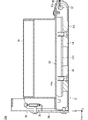
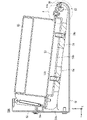
次に、映像表示モジュール1000を筐体10から着脱する際に使用される映像表示モジュール着脱治具50について説明を行う。図7は、映像表示モジュール着脱治具50のカバー53が閉じた状態を示す斜視図である。図8は、図7のB-B線断面図である。図9は、映像表示モジュール着脱治具50のカバー53が開いた状態を示す斜視図である。図10は、図9のC-C線断面図である。
次に、映像表示モジュール1000を筐体10から着脱する際に使用される映像表示モジュール着脱治具50について説明を行う。図7は、映像表示モジュール着脱治具50のカバー53が閉じた状態を示す斜視図である。図8は、図7のB-B線断面図である。図9は、映像表示モジュール着脱治具50のカバー53が開いた状態を示す斜視図である。図10は、図9のC-C線断面図である。
図7と図8に示すように、映像表示モジュール着脱治具50は、ケース51と、プレート52と、カバー53と、磁石54と、ハンドル55と、ばね56とを備える。
ケース51は、XY面に平行な平面を有する底部51aと、底部51aの+Y側端から立設する側部51bと、底部51aの+X側端から立設する側部51cと、底部51aの-X側端から立設する側部51dとを備える。底部51aのXY面に平行な平面は、映像表示モジュール1000の前面に当接する当接部である。底部51aにおける当接部よりも-Y側の部分は、+Z方向に延びる円弧状に形成される。
プレート52は、+Z方向に延びる形状を有し、ケース51の側部51bに固定される。プレート52は、作業者がハンドル55を引く際に作業者の手を当てるガイドとして機能する。
カバー53は、+Z側に配置された平板状の上板部53aと、-Z側に配置された凹状の下板部53bと、上板部53aと下板部53bの+X側端に配置された側板部53c(図9参照)と、上板部53aと下板部53bの-X側端に配置された側板部53d(図9参照)とで構成される。カバー53は、回転軸57を中心にケース51に対して開閉可能に取り付けられる。回転軸57は、ケース51の側部51b,51cの-Y側端部に設けられ、ケース51の側部51b,51cおよびカバー53の側板部53c,53dに挿通される。
磁石54は、カバー53におけるケース51の当接部を挟んで反対側の位置にY軸方向に並んで2つ設けられている。具体的には、2つの磁石54は、カバー53の下板部53bの-Z側の面にねじ止めされる。映像表示モジュール着脱治具50が映像表示モジュール1000の前面に当接した状態で、2つの磁石54は、映像表示モジュール1000に設けられたプレート3と磁気カップリングを形成する。
ハンドル55は、カバー53に設けられる。具体的には、ハンドル55の一端部はカバー53の上板部53aの-Y側端部に固定され、ハンドル55の他端部はカバー53の上板部53aの+Y側端部に固定される。
ばね56の一端はハンドル55に接続され、ばね56の他端はプレート52を介してケース51の側部51bに接続される。ばね56は、カバー53を開閉可能な張力でプレート52とハンドル55とを連結しており、カバー53が閉じる方向にハンドル55を付勢する。
図7と図8に示すように、映像表示モジュール着脱治具50では、ハンドル55が操作されない場合、ばね56の付勢力によりカバー53は閉じた状態となる。また、図9と図10に示すように、映像表示モジュール着脱治具50では、ハンドル55に+Z軸方向の引き上げ力が加わると、回転軸57を回転中心としてカバー53は引き上げられ開いた状態となる。
このとき、カバー53に固定された磁石54もカバー53に連動して引き上げられるため、磁石54とケース51との間にギャップが生じる。カバー53が開いた状態のとき、ハンドル55を引く力が弱くなると、ばね56の付勢力によってハンドル55が引き戻されてカバー53は再び閉じた状態となる。
図11は、映像表示装置100から映像表示モジュール1000を取り外す際に映像表示モジュール着脱治具50を取り付けた状態を示す断面図である。図12は、図11の領域Dの拡大図である。
図11と図12に示すように、映像表示装置100の前方から映像表示モジュール1000の前面へ映像表示モジュール着脱治具50を近づけると、映像表示モジュール着脱治具50に設けられた磁石54と、映像表示モジュール1000に設けられたプレート3との間に磁気カップリングが形成され、吸着力61が発生する。
ここで、吸着力61の大きさをF61、磁石11と磁石吸着体4との間に発生する吸着力60の大きさをF60、コネクタ2とコネクタ22の引抜力62の大きさをF62とすると、それぞれ力の大きさの関係は式1を満たす。

このとき、映像表示モジュール着脱治具50を+Z方向に引き出すことで筐体10から映像表示モジュール1000を取り外すことが可能となる。ここで、映像表示モジュール着脱治具50を引く力の大きさをF50とすると、F50は式2を満たす。

F50が式2を満たすとき、カバー53が開いた状態のまま映像表示モジュール1000を筐体10から取り外すことができる。
なお、図11に示す例では、プレート3は映像表示モジュール着脱治具50に設けられた2つの磁石54と磁気カップリングを形成しているが、磁石54の個数は、吸着力に応じて例えば1つまたは4つに変更可能である。
図11と図12に示すように、映像表示モジュール着脱治具50を映像表示モジュール1000に近づけると、映像表示モジュール着脱治具50に設けられた磁石54と映像表示モジュール1000に設けられた磁性体であるプレート3との間に吸着力61が発生する。吸着力61が大きい場合、映像表示モジュール1000は映像表示モジュール着脱治具50に急に引き寄せられる。
また、映像表示モジュール着脱治具50を映像表示モジュール1000から取り外そうとすると、瞬間的に大きな力が必要である。これらの場合、複数の映像表示モジュール1000が配置された映像表示装置100が、LED表示素子の画素ピッチ(例えば、1mm以上2mm以下)にて配置されており、組立時またはメンテナンス時に映像表示モジュール1000のハンドリングを誤ると、隣接する他の映像表示モジュール1000のLED表示素子またはその周辺部材に接触し破損させる恐れがある。
ところで、吸着力61を小さくするためには、映像表示モジュール1000に設けられた磁石吸着体4と筐体10に設けられた磁石11との間に発生する吸着力60を小さくする必要がある。これを実現しようとすると、筐体10に対する映像表示モジュール1000の保持強度が弱くなる。
本実施の形態では、映像表示モジュール着脱治具50に設けられた磁石54と映像表示モジュール1000に設けられたプレート3との距離を調整することができる。これにより、磁石54とプレート3との距離を離すことで、映像表示モジュール着脱治具50を映像表示モジュール1000に近づけるとき、または映像表示モジュール1000から取り外すときに、筐体10に対する映像表示モジュール1000の保持強度を維持しつつ、吸着力61を小さくすることが可能となる。よって、映像表示モジュール1000のハンドリングが容易となり、映像表示モジュール1000を破損させるなどの問題を解消することができる。
図13は、映像表示装置100から映像表示モジュール着脱治具50を着脱する際の状態を示す断面図である。図14は、図13の領域Eの拡大図である。
映像表示モジュール1000に映像表示モジュール着脱治具50を近づける際は、カバー53は開いた状態であり、磁石54とプレート3との間に発生する吸着力61は小さい。ハンドル55を引き上げる力を徐々に小さくし、ハンドル55をカバー53が閉じた状態となる位置まで戻す。このとき、図13と図14に示すように、プレート3と磁石54とのギャップは小さいため、吸着力61は大きくなる。
映像表示モジュール着脱治具50を映像表示モジュール1000から取り外す際は、ハンドル55を+Z方向に引き、カバー53を開けた状態にすると、磁石54とプレート3とのギャップが大きくなり吸着力61は小さくなる。このとき、映像表示モジュール着脱治具50を+Z方向に引き離すと、映像表示モジュール1000は磁石11と磁石吸着体4との間に発生する吸着力60によって筐体10に固定されたまま、映像表示モジュール着脱治具50を映像表示モジュール1000から取り外すことができる。
(効果)
以上のように、実施の形態1では、映像表示モジュール着脱治具50は、映像表示モジュール1000の前面に当接する当接部を有するケース51と、回転軸57を中心にケース51に対して開閉可能に取り付けられたカバー53と、カバー53におけるケース51の当接部を挟んで反対側の位置に設けられ、かつ、映像表示モジュール1000に設けられた磁性体であるプレート3と磁気カップリングを形成する磁石54と、カバー53に設けられたハンドル55とを備え、ハンドル55に対する操作に連動してカバー53が開閉することで磁石54とプレート3との距離を調整する。
以上のように、実施の形態1では、映像表示モジュール着脱治具50は、映像表示モジュール1000の前面に当接する当接部を有するケース51と、回転軸57を中心にケース51に対して開閉可能に取り付けられたカバー53と、カバー53におけるケース51の当接部を挟んで反対側の位置に設けられ、かつ、映像表示モジュール1000に設けられた磁性体であるプレート3と磁気カップリングを形成する磁石54と、カバー53に設けられたハンドル55とを備え、ハンドル55に対する操作に連動してカバー53が開閉することで磁石54とプレート3との距離を調整する。
したがって、ハンドル55に対する操作を行うことで磁石54とプレート3との距離を調整することができるため、映像表示モジュール1000と映像表示モジュール着脱治具50との間の磁気カップリングを制御することができる。これにより、映像表示モジュール1000から映像表示モジュール着脱治具50を取り外すときに強い力は不要となる。
さらに、ハンドル55に対する操作を行うことで映像表示モジュール1000と映像表示モジュール着脱治具50との間の磁気カップリングを制御することができるため、映像表示モジュール着脱治具50に電力を供給するためのバッテリーまたは外部電源は不要となる。これにより、映像表示モジュール着脱治具50が大型化しないため、映像表示モジュール1000のハンドリングは容易である。以上より、大画面を構成する映像表示装置100から映像表示モジュール1000の着脱を容易に行うことができる。
また、ハンドル55が引き上げられてカバー53が開いた状態で、磁石54とプレート3とが離間し、ハンドル55が引き下げられてカバー53が閉じた状態で、磁石54とプレート3とが近接する。
したがって、作業者はハンドル55の位置に基づいて、磁石54とプレート3との吸着力の強弱を視覚的に容易に見分けることができる。これにより、作業者が誤って吸着力が強い状態で映像表示モジュール着脱治具50を映像表示モジュール1000に近づけて、映像表示モジュール着脱治具50が映像表示モジュール1000に急に引き寄せられることで、映像表示モジュール1000が破損することを抑制できる。
また、映像表示モジュール着脱治具50は、一端がハンドル55に接続され、かつ、他端がケース51に接続されたばね56をさらに備え、ばね56は、カバー53が閉じる方向にハンドル55を付勢する。
したがって、映像表示装置100から映像表示モジュール1000を着脱する際に、カバー53を閉じた状態にするためにハンドル55に対する操作を行う必要がないため、作業者の負担が軽減される。
また、映像表示モジュール1000から映像表示モジュール着脱治具50を取り外す際に、ケース51は映像表示モジュール1000に対して面で接触する。このように、ケース51は映像表示モジュール1000に対して点で接触しないため、映像表示モジュール1000の一部分に大きな力が働くことなく、映像表示モジュール1000が破損することを抑制できる。
<実施の形態2>
次に、実施の形態2に係る映像表示モジュール着脱治具50Aについて説明する。図15は、実施の形態2に係る映像表示モジュール着脱治具50Aのカバー53が閉じた状態を示す斜視図である。図16は、映像表示モジュール着脱治具50Aのカバー53が開いた状態を示す斜視図である。図17は、図16の領域Fの拡大図である。なお、実施の形態2において、実施の形態1で説明したものと同一の構成要素については同一符号を付して説明は省略する。
次に、実施の形態2に係る映像表示モジュール着脱治具50Aについて説明する。図15は、実施の形態2に係る映像表示モジュール着脱治具50Aのカバー53が閉じた状態を示す斜視図である。図16は、映像表示モジュール着脱治具50Aのカバー53が開いた状態を示す斜視図である。図17は、図16の領域Fの拡大図である。なお、実施の形態2において、実施の形態1で説明したものと同一の構成要素については同一符号を付して説明は省略する。
実施の形態1では、映像表示モジュール着脱治具50を映像表示モジュール1000に近づける、または映像表示モジュール1000から取り外す際には、カバー53を開けた状態で作業が行われるため、作業の間、作業者はハンドル55を引き続ける必要がある。ハンドル55を引く力が不十分となり、ばね56の付勢力によりカバー53が勢いよく閉じた状態に戻った場合、映像表示モジュール1000に衝撃を与えて破損する可能性がある。
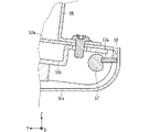
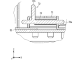
このような問題を解決するために、図15~図17に示すように、実施の形態2では、映像表示モジュール着脱治具50Aは、カバー53を開けた状態で回転軸57の回転位置を固定する固定ねじ58をさらに備える。
固定ねじ58は、ケース51の底部51aにおける円弧状に延びる部分の内面側に設けられる。回転軸57には、固定ねじ58の先端部が係合可能な溝57aが設けられる。カバー53を開けた状態で固定ねじ58が締められて、固定ねじ58の先端部が回転軸57の溝57aに係合することで、回転軸57の回転位置が固定される。なお、固定ねじ58の先端部とは、固定ねじ58における回転軸57側に突出する部分である。
固定ねじ58の先端部が回転軸57の溝57aに係合していないとき、回転軸57は固定されておらず、作業者がハンドル55を+Z方向に引くことでカバー53は閉じた状態から開いた状態に変化する。カバー53が開いた状態で、固定ねじ58の先端部が回転軸57の溝57aに係合すると、回転軸57の回転が妨げられ、カバー53は開いた状態で保持される。固定ねじ58が緩められ、固定ねじ58の先端部と回転軸57の溝57aとの係合が解除されると、カバー53はばね56の付勢力によって再び閉じた状態に戻る。
(効果)
以上のように、実施の形態2では、回転軸57は、ケース51およびカバー53に挿通され、映像表示モジュール着脱治具50Aは、カバー53を開けた状態で回転軸57の回転位置を固定する固定ねじ58をさらに備える。
以上のように、実施の形態2では、回転軸57は、ケース51およびカバー53に挿通され、映像表示モジュール着脱治具50Aは、カバー53を開けた状態で回転軸57の回転位置を固定する固定ねじ58をさらに備える。
したがって、カバー53を開けた状態で保持することができるため、映像表示モジュール着脱治具50Aを映像表示モジュール1000に近づける、または映像表示モジュール1000から取り外す際に、作業者は作業の間ハンドル55を引き続ける必要がなくなる。これにより、作業者の負担を軽減し容易かつ安全な映像表示モジュール1000のハンドリングが可能となる。
<実施の形態3>
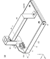
次に、実施の形態3に係る映像表示モジュール着脱治具50Bについて説明する。図18は、実施の形態3に係る映像表示モジュール着脱治具50Bのカバー53が閉じた状態を示す斜視図である。図19は、映像表示モジュール着脱治具50Bのカバー53が閉じた状態を示す別の方向から視た斜視図である。図20は、図19のG-G線断面図である。図21は、図20の領域Hの拡大図である。図22は、映像表示モジュール着脱治具50Bのカバー53が閉じた状態を保持した状態を示す斜視図である。図23は、映像表示モジュール着脱治具50Bのカバー53が閉じた状態を保持した状態を示す別の方向から視た斜視図である。図24は、図23のJ-J線断面図である。図25は、図24の領域Kの拡大図である。なお、実施の形態3において、実施の形態1,2で説明したものと同一の構成要素については同一符号を付して説明は省略する。
次に、実施の形態3に係る映像表示モジュール着脱治具50Bについて説明する。図18は、実施の形態3に係る映像表示モジュール着脱治具50Bのカバー53が閉じた状態を示す斜視図である。図19は、映像表示モジュール着脱治具50Bのカバー53が閉じた状態を示す別の方向から視た斜視図である。図20は、図19のG-G線断面図である。図21は、図20の領域Hの拡大図である。図22は、映像表示モジュール着脱治具50Bのカバー53が閉じた状態を保持した状態を示す斜視図である。図23は、映像表示モジュール着脱治具50Bのカバー53が閉じた状態を保持した状態を示す別の方向から視た斜視図である。図24は、図23のJ-J線断面図である。図25は、図24の領域Kの拡大図である。なお、実施の形態3において、実施の形態1,2で説明したものと同一の構成要素については同一符号を付して説明は省略する。
実施の形態1では、吸着力61の大きさは式1を満たすが、吸着力61が大きくなるにつれてカバー53を閉じた状態から開いた状態に変化させるためにハンドル55を引く力が大きくなり、作業者の負担が増える。また、映像表示モジュール1000が映像表示モジュール着脱治具50に引き寄せられやすくなるため、映像表示モジュール1000が破損する可能性も高くなる。したがって、吸着力61は式1を満たす範囲で小さくすることが望ましい。
しかし、吸着力61が式1を満たす範囲で小さくなると、映像表示モジュール着脱治具50を用いて映像表示モジュール1000を筐体10から取り外す際に映像表示モジュール着脱治具50を引く力が式2を満たさず、吸着力61よりも大きな力で映像表示モジュール着脱治具50を引いてしまう可能性がある。ケース51とカバー53は回転軸57のみで連結されているため、映像表示モジュール着脱治具50を引く力が吸着力61よりも大きい場合、ハンドル55が固定されたカバー53のみが引っ張られることで、カバー53は開いた状態に変化する。カバー53が開いた状態では吸着力61が小さくなるため、映像表示モジュール着脱治具50が映像表示モジュール1000から離れてしまい、映像表示モジュール1000を破損する可能性がある。
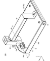
このような問題を解決するために、実施の形態3では、図18~図25に示すように、実施の形態3では、映像表示モジュール着脱治具50Bは、ケース51に設けられた溝70と、カバー53に固定されたホルダー71と、ホルダー71に設けられかつ溝70に係合可能なピン72と、ピン72に装着されたばね73とをさらに備える。図22に示すように、ピン72が、カバー53を閉じた状態で溝70に係合することで、カバー53を閉じた状態で保持可能とする。
ピン72は、ホルダー71を挿通した状態でホルダー71に取り付けられる。ピン72は、ピン72の回転軸として機能する軸部72aと、軸部72aに対して垂直方向に突出する突出部72bとを備え、軸部72aと突出部72bとでT字状を形成する。ホルダー71は直方体状であり、ホルダー71の+Z側の面にはX軸方向に延び、かつ、途中部から+Y側の面にかけて延びる溝71aが形成される。
ピン72は軸部72aを回転軸としてX軸方向を中心に回転可能である。ピン72に装着されたばね73は、ピン72の突出部72bが+Z方向を向き、かつ、ピン72の軸部72aが+X方向に位置するようにピン72を付勢する。ケース51の側部51bには、L字状の溝70が形成される。溝71aおよび溝70は、ピン72の回転に伴ってピン72の突出部72bが通ることが可能な幅を有する。
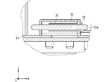
図18~図21に示すように、突出部72bが+Z方向を向いた状態で、ピン72を-X方向にスライドさせホルダー71に形成された溝71aに沿ってX軸方向を中心に正方向に回転させると、図22~図25に示すように、ピン72はばね73の付勢力によって+X方向にスライドする。このとき、突出部72bは、ケース51の側部51bに形成された溝70に係合されるため、+Y方向を向いた状態で保持される。なお、正方向とは、+X方向から-X方向を視て反時計回りの方向をいう。
突出部72bが+Y方向を向いた状態で、ピン72を-X方向にスライドさせホルダー71に形成された溝71aに沿ってX軸方向を中心に逆方向に回転させると、ピン72はばね73の付勢力によって+X方向にスライドし、再びピン72は+Z方向を向いた状態で保持される。なお、逆方向とは、+X方向から-X方向を視て時計回りの方向をいう。
図18~図21に示すように、突出部72bが+Z方向を向いた状態では、ハンドル55に対する操作が行われることで、カバー53が閉じた状態と開いた状態とに変化させることが可能である。
一方、図22~図25に示すように、突出部72bが+Y方向を向いた状態では、プレート52を押さえながらハンドル55を+Z方向に引いた場合、ピン72が溝70に係合し溝70から抜けないため、カバー53は閉じた状態から開いた状態に変化せず、閉じた状態のまま保持される。
(効果)
以上のように、実施の形態3では、映像表示モジュール着脱治具50Bは、ケース51に設けられた溝70と、カバー53に固定されたホルダー71と、ホルダー71に設けられかつ溝70に係合可能なピン72とをさらに備え、ピン72は、カバー53を閉じた状態で溝70に係合する。
以上のように、実施の形態3では、映像表示モジュール着脱治具50Bは、ケース51に設けられた溝70と、カバー53に固定されたホルダー71と、ホルダー71に設けられかつ溝70に係合可能なピン72とをさらに備え、ピン72は、カバー53を閉じた状態で溝70に係合する。
したがって、映像表示モジュール着脱治具50Bを用いて映像表示モジュール1000を筐体10から取り外す際に、吸着力61よりも大きな力で映像表示モジュール着脱治具50Bを引いた場合にも、カバー53は開いた状態に変化しないため、映像表示モジュール着脱治具50Bが映像表示モジュール1000から離れることを抑制できる。これにより、小さな吸着力61で映像表示モジュール1000を筐体10から安全に取り外すことが可能となり、映像表示モジュール1000の破損を抑制できる。
この開示は詳細に説明されたが、上記した説明は、すべての局面において、例示であって、限定的なものではない。例示されていない無数の変形例が、想定され得るものと解される。
なお、各実施の形態を自由に組み合わせたり、各実施の形態を適宜、変形、省略することが可能である。
3 プレート、10 筐体、50,50A,50B 映像表示モジュール着脱治具、51 ケース、53 カバー、54 磁石、55 ハンドル、56 ばね、57 回転軸、58 固定ねじ、70 溝、71 ホルダー、72 ピン、100~106 映像表示装置、1000~1008 映像表示モジュール。
Claims (5)
- 筐体に複数の映像表示モジュールを固定し大画面を構成する映像表示装置から前記映像表示モジュールを着脱する映像表示モジュール着脱治具であって、
前記映像表示モジュールの前面に当接する当接部を有するケースと、
回転軸を中心に前記ケースに対して開閉可能に取り付けられたカバーと、
前記カバーにおける前記ケースの前記当接部を挟んで反対側の位置に設けられ、かつ、前記映像表示モジュールに設けられた磁性体と磁気カップリングを形成する磁石と、
前記カバーに設けられたハンドルと、を備え、
前記ハンドルに対する操作に連動して前記カバーが開閉することで前記磁石と前記磁性体との距離を調整する、映像表示モジュール着脱治具。 - 前記ハンドルが引き上げられて前記カバーが開いた状態で、前記磁石と前記磁性体とが離間し、
前記ハンドルが引き下げられて前記カバーが閉じた状態で、前記磁石と前記磁性体とが近接する、請求項1に記載の映像表示モジュール着脱治具。 - 一端が前記ハンドルに接続され、かつ、他端が前記ケースに接続されたばねをさらに備え、
前記ばねは、前記カバーが閉じる方向に前記ハンドルを付勢する、請求項1または請求項2に記載の映像表示モジュール着脱治具。 - 前記回転軸は、前記ケースおよび前記カバーに挿通され、
前記映像表示モジュール着脱治具は、前記カバーを開けた状態で前記回転軸の回転位置を固定する固定ねじをさらに備えた、請求項1から請求項3のいずれか1項に記載の映像表示モジュール着脱治具。 - 前記ケースに設けられた溝と、前記カバーに固定されたホルダーと、前記ホルダーに設けられかつ前記溝に係合可能なピンとをさらに備え、
前記ピンは、前記カバーを閉じた状態で前記溝に係合する、請求項1から請求項3のいずれか1項に記載の映像表示モジュール着脱治具。
Priority Applications (1)
| Application Number | Priority Date | Filing Date | Title |
|---|---|---|---|
| PCT/JP2021/000181 WO2022149205A1 (ja) | 2021-01-06 | 2021-01-06 | 映像表示モジュール着脱治具 |
Applications Claiming Priority (1)
| Application Number | Priority Date | Filing Date | Title |
|---|---|---|---|
| PCT/JP2021/000181 WO2022149205A1 (ja) | 2021-01-06 | 2021-01-06 | 映像表示モジュール着脱治具 |
Publications (1)
| Publication Number | Publication Date |
|---|---|
| WO2022149205A1 true WO2022149205A1 (ja) | 2022-07-14 |
Family
ID=82358172
Family Applications (1)
| Application Number | Title | Priority Date | Filing Date |
|---|---|---|---|
| PCT/JP2021/000181 Ceased WO2022149205A1 (ja) | 2021-01-06 | 2021-01-06 | 映像表示モジュール着脱治具 |
Country Status (1)
| Country | Link |
|---|---|
| WO (1) | WO2022149205A1 (ja) |
Citations (8)
| Publication number | Priority date | Publication date | Assignee | Title |
|---|---|---|---|---|
| CN105810109A (zh) * | 2016-04-16 | 2016-07-27 | 深圳市艾比森光电股份有限公司 | 一种led显示屏模组的前维护工具和前维护结构 |
| CN106558281A (zh) * | 2015-09-28 | 2017-04-05 | 深圳市艾比森光电股份有限公司 | Led显示屏、led显示屏前维护装置和方法 |
| WO2017215163A1 (zh) * | 2016-06-17 | 2017-12-21 | 深圳市创显光电有限公司 | Led 显示屏前维护气吸工具 |
| JP2018506748A (ja) * | 2014-12-29 | 2018-03-08 | プレイナー システムス インコーポレーテッドPlanar Systems, Incorporated | 磁気誘導位置決め手段が隠蔽されるマウント |
| CN207529594U (zh) * | 2017-10-31 | 2018-06-22 | 深圳市联建光电股份有限公司 | 一种led显示屏维护工具 |
| US20180186145A1 (en) * | 2017-01-03 | 2018-07-05 | Boe Technology Group Co., Ltd. | Attachment device, attachment system and method for attaching protection film using attachment system |
| JP2019003187A (ja) * | 2017-06-12 | 2019-01-10 | クリスティ デジタル システムズ ユーエスエイ インコーポレイテッド | タイル状ディスプレイ位置合わせ用治具 |
| JP2019066831A (ja) * | 2017-09-05 | 2019-04-25 | クリスティ デジタル システムズ ユーエスエイ インコーポレイテッド | タイル状ディスプレイの取り外しのための装置および方法 |
-
2021
- 2021-01-06 WO PCT/JP2021/000181 patent/WO2022149205A1/ja not_active Ceased
Patent Citations (8)
| Publication number | Priority date | Publication date | Assignee | Title |
|---|---|---|---|---|
| JP2018506748A (ja) * | 2014-12-29 | 2018-03-08 | プレイナー システムス インコーポレーテッドPlanar Systems, Incorporated | 磁気誘導位置決め手段が隠蔽されるマウント |
| CN106558281A (zh) * | 2015-09-28 | 2017-04-05 | 深圳市艾比森光电股份有限公司 | Led显示屏、led显示屏前维护装置和方法 |
| CN105810109A (zh) * | 2016-04-16 | 2016-07-27 | 深圳市艾比森光电股份有限公司 | 一种led显示屏模组的前维护工具和前维护结构 |
| WO2017215163A1 (zh) * | 2016-06-17 | 2017-12-21 | 深圳市创显光电有限公司 | Led 显示屏前维护气吸工具 |
| US20180186145A1 (en) * | 2017-01-03 | 2018-07-05 | Boe Technology Group Co., Ltd. | Attachment device, attachment system and method for attaching protection film using attachment system |
| JP2019003187A (ja) * | 2017-06-12 | 2019-01-10 | クリスティ デジタル システムズ ユーエスエイ インコーポレイテッド | タイル状ディスプレイ位置合わせ用治具 |
| JP2019066831A (ja) * | 2017-09-05 | 2019-04-25 | クリスティ デジタル システムズ ユーエスエイ インコーポレイテッド | タイル状ディスプレイの取り外しのための装置および方法 |
| CN207529594U (zh) * | 2017-10-31 | 2018-06-22 | 深圳市联建光电股份有限公司 | 一种led显示屏维护工具 |
Similar Documents
| Publication | Publication Date | Title |
|---|---|---|
| CN109961696B (zh) | 多面板显示装置 | |
| RU2738104C1 (ru) | Устройство отображения изображений и многодисплейная система | |
| CN111344772B (zh) | 显示装置及其拆卸方法 | |
| EP3731219A1 (en) | Video display device and multi-display system | |
| US10635381B2 (en) | Multi-display system, video display device, and pull-out mechanism | |
| CN109979335B (zh) | 显示模块和显示装置 | |
| CN112447106B (zh) | 显示设备 | |
| CN111326072B (zh) | 拼接显示器及用于组装其的方法和拼接工具 | |
| TWI780958B (zh) | 顯示裝置及拼接顯示裝置 | |
| CN111542778A (zh) | 显示装置和显示模块的铰链组件 | |
| JP2019003187A (ja) | タイル状ディスプレイ位置合わせ用治具 | |
| WO2020178911A1 (ja) | マルチディスプレイシステムおよび映像表示装置 | |
| US11917770B2 (en) | Display apparatus | |
| US12501570B2 (en) | Bearing box and splicing display apparatus | |
| CN114721208B (zh) | 一种投影仪壳体 | |
| CN1759429B (zh) | 平板型图像显示装置 | |
| WO2022149205A1 (ja) | 映像表示モジュール着脱治具 | |
| JP2015126396A (ja) | ヘッドマウントディスプレイ | |
| US9765922B2 (en) | Display apparatus | |
| US20250285563A1 (en) | Display apparatus | |
| CN218920516U (zh) | 外接摄像头支架、外接摄像模组以及显示系统 | |
| WO2022085066A1 (ja) | 映像表示装置およびマルチディスプレイシステム | |
| US20250071922A1 (en) | Connection bracket and display apparatus including the same | |
| EP4621760A1 (en) | Separation device and display device comprising same | |
| CN2810063Y (zh) | 液晶电视结构改良 |
Legal Events
| Date | Code | Title | Description |
|---|---|---|---|
| 121 | Ep: the epo has been informed by wipo that ep was designated in this application |
Ref document number: 21917433 Country of ref document: EP Kind code of ref document: A1 |
|
| NENP | Non-entry into the national phase |
Ref country code: DE |
|
| 122 | Ep: pct application non-entry in european phase |
Ref document number: 21917433 Country of ref document: EP Kind code of ref document: A1 |
|
| NENP | Non-entry into the national phase |
Ref country code: JP |