WO2022145134A1 - コネクタ、及びソケットの集合体 - Google Patents
コネクタ、及びソケットの集合体 Download PDFInfo
- Publication number
- WO2022145134A1 WO2022145134A1 PCT/JP2021/041382 JP2021041382W WO2022145134A1 WO 2022145134 A1 WO2022145134 A1 WO 2022145134A1 JP 2021041382 W JP2021041382 W JP 2021041382W WO 2022145134 A1 WO2022145134 A1 WO 2022145134A1
- Authority
- WO
- WIPO (PCT)
- Prior art keywords
- socket
- holding
- pair
- protruding
- portions
- Prior art date
- Legal status (The legal status is an assumption and is not a legal conclusion. Google has not performed a legal analysis and makes no representation as to the accuracy of the status listed.)
- Ceased
Links
Images











Classifications
-
- H—ELECTRICITY
- H01—ELECTRIC ELEMENTS
- H01R—ELECTRICALLY-CONDUCTIVE CONNECTIONS; STRUCTURAL ASSOCIATIONS OF A PLURALITY OF MUTUALLY-INSULATED ELECTRICAL CONNECTING ELEMENTS; COUPLING DEVICES; CURRENT COLLECTORS
- H01R13/00—Details of coupling devices of the kinds covered by groups H01R12/70 or H01R24/00 - H01R33/00
- H01R13/02—Contact members
- H01R13/22—Contacts for co-operating by abutting
- H01R13/24—Contacts for co-operating by abutting resilient; resiliently-mounted
-
- H—ELECTRICITY
- H01—ELECTRIC ELEMENTS
- H01R—ELECTRICALLY-CONDUCTIVE CONNECTIONS; STRUCTURAL ASSOCIATIONS OF A PLURALITY OF MUTUALLY-INSULATED ELECTRICAL CONNECTING ELEMENTS; COUPLING DEVICES; CURRENT COLLECTORS
- H01R33/00—Coupling devices specially adapted for supporting apparatus and having one part acting as a holder providing support and electrical connection via a counterpart which is structurally associated with the apparatus, e.g. lamp holders; Separate parts thereof
- H01R33/74—Devices having four or more poles, e.g. holders for compact fluorescent lamps
- H01R33/76—Holders with sockets, clips, or analogous contacts adapted for axially-sliding engagement with parallely-arranged pins, blades, or analogous contacts on counterpart, e.g. electronic tube socket
Definitions
- the present invention relates to a connector and an aggregate of sockets constituting the connector.
- a connector that electrically connects a plurality of first terminals and second terminals to each other is known.
- a connector having a cylinder body formed in an elongated cylinder shape, a contactor housed inside the cylinder body and in a conductive state with the cylinder body, and a holding body for holding the cylinder body is known. ing.
- An object of the present invention is to provide a connector that makes it difficult for a socket to come off from a holding member that holds a socket and that makes it easy for the socket to increase the force for holding a contact, and an aggregate of sockets constituting the connector. ..
- a connector includes a cylindrical socket, a contact having a rod shape and having a first portion that can be located in the socket and a second portion that protrudes from one end of the socket.
- a holding member having a holding hole for accommodating the socket is provided, and a pair of slits extending in parallel with each other are formed on the peripheral wall of the socket, and the holding portion which is a portion sandwiched by the pair of slits is a holding portion.
- the holding portion includes a protruding portion protruding into the socket and a non-protruding portion connected to the protruding portion, and the holding portion causes the protruding portion to protrude into a space in the socket when the first portion is not located in the socket.
- the non-projecting portion is in a protruding posture, and the non-projecting portion does not project radially inward from the inner circumference of the socket in the protruding posture.
- the aggregate of sockets is an aggregate of the sockets in the above-mentioned connector, and includes a carrier for transporting the socket and a plurality of the sockets transported together with the carrier.
- the carrier is provided with a plurality of connecting portions in which the axial end portions of the socket are detachably connected to each other at regular intervals.
- FIG. 4 is a sectional view taken along line VV of FIG.
- FIG. 4 is a sectional view taken along line VI-VI of FIG.
- FIG. 4 is a sectional view taken along line VII-VII of FIG.
- FIG. 3 is an enlarged three-view view showing the holding portion 25. It is a VII-VII line sectional view in a state where a contact 10 is inserted in a socket 20.
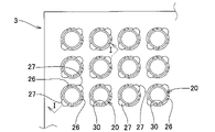
- FIG. 13 is a sectional view taken along line XIV-XIV of FIG. It is a front view which shows the manufacturing process of the assembly of sockets 20. It is sectional drawing which shows the accommodation state of the socket 20. It is a top view which shows the state which the socket 20 is accommodated in all accommodation holes.
- FIG. 22 is a partial cross-sectional view showing a state in which the contactor 10 is inserted into the socket 20 shown in FIG. 21. It is a plan sectional view which shows the modification of the assembly of sockets 20. It is a top view which shows the state which the socket is accommodated in a part of accommodation holes.
- FIG. 1 shows a cross-sectional view taken along the line I-I of FIG.
- the vertical direction in each figure is defined with reference to the longitudinal direction of the contactor unit 2, and the upper side of each figure is the tip end side in the longitudinal direction of the contactor unit 2, and the lower side of each figure.
- the side is the base end side in the longitudinal direction of the contactor unit 2.
- the direction perpendicular to the vertical direction is described as the horizontal direction.
- the connector 1 shown in FIG. 1 electrically connects a plurality of first terminals A and a plurality of second terminals B.
- the first terminal A of the connection switching unit (not shown) which is the first connection target is connected to the base end portion of the connector 1, and the inspection jig connector which is the second connection target (not shown).
- the case where the second terminal B (not shown) is connected to the tip end portion of the connector 1 is illustrated.
- the first terminal A and the second terminal B are conductively connected to each other via the contact unit 2 provided on the connector 1.
- the connection switching unit is, for example, a so-called scanner device used for a board inspection device for inspecting the electrical characteristics of a wiring pattern provided on a board.
- This scanner device is between an inspection unit provided with a power supply unit, a voltage detection unit, and a current detection unit for inspection of the main body of the inspection device and a contact provided in a connector for an inspection jig which is a second connection target. It switches the electrical connection relationship of.
- connection switching unit for example, a plurality of first terminals A composed of electrode pins connected to a plurality of switching elements are arranged at a predetermined pitch. Then, a plurality of first terminals A are projected from the connection switching unit arranged on the lower side of FIG. 1 toward the base end portion side of the connector 1.
- a plurality of second terminals B composed of electrode pins and the like are arranged at a predetermined pitch in the inspection jig connector.
- the second terminal B is connected to each contactor of the inspection jig, which is pressed against an inspection point such as a wiring pattern to be inspected, via a conducting wire. Then, a plurality of second terminals B are projected from the inspection jig connector arranged on the upper side of FIG. 1 toward the tip end side of the connector 1.
- the connector 1 is not limited to the one that relays between the connection switching unit and the connector for the inspection jig, and can be applied to various other uses. That is, the connection target connected to the base end portion of the connector 1 is not limited to the first terminal A provided in the connection switching unit. Further, the connection target connected to the tip of the connector 1 is not limited to the second terminal B provided in the inspection jig connector.
- the connector 1 includes a plurality of contactor units 2 having a contactor 10, a base plate 3 as an example of a holding member, and a cover plate 4 as an example of a cover member.
- the connector is not limited to the example in which a plurality of contactor units 2 are provided, and may be a connector having only one contactor unit 2.
- the base plate 3 is formed with a plurality of circular accommodating holes 30 that penetrate the base plate 3 in the thickness direction.
- the cover plate 4 is formed with a plurality of circular holes 50 that penetrate the cover plate 4 in the thickness direction.
- the inner diameters of the accommodating hole 30 and the hole 50 are both set to the inner diameter D.
- the inner diameter of the accommodating hole 30 and the inner diameter of the hole 50 may be different.
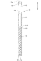
- the contact 10 has a substantially rod-like shape as a whole, and has a tubular body 11 formed in a substantially cylindrical shape by a conductive member and a plunger 12 formed in a rod shape by a conductive member. And a coil spring 13 arranged in the tubular body 11.
- the tubular body 11 corresponds to an example of the first portion located in the socket 20, and the portion protruding from the tubular body 11 of the plunger 12 and the cup 13 correspond to an example of the second portion. is doing.
- a cup 13 having a diameter larger than that of the plunger 12 is provided at the tip of the plunger 12.
- a funnel portion 13a recessed in a funnel shape is formed at the tip of the cup 13.
- the cup 13 has a larger diameter than the second terminal B.
- the cup 13 is not limited to the example provided at the tip of the plunger 12.
- the tip of the plunger 12 may have a substantially conical pointed shape as in the plunger 12a shown in FIG. 3, or a so-called crown shape having a plurality of protrusions as in the plunger 12b. May be good.
- the tip of the plunger 12 may have various shapes that can be easily contacted with the second terminal B.
- the configuration of the cover plate 4a shown in FIG. 3 will be described later.
- a tip opening 11a is formed at the tip of the tubular body 11 located on the upper side of FIG. 2.
- a bottom wall 11b having a base end opening 11c is provided at the base end portion of the tubular body 11 located on the lower side of FIG.
- the base end side of the plunger 12 is configured to be insertable into the tubular body 11 from the tip opening 11a.
- a reduced diameter portion 11d obtained by deforming a part of the tubular body 11 so as to be recessed inward is provided.
- a bulging portion 121 having an outer diameter slightly larger than the inner diameter of the reduced diameter portion 11d of the tubular body 11 is provided at the base end portion of the plunger 12.
- the bulging portion 121 is inserted into the tubular body 11 and pushed toward the base end portion side with respect to the reduced diameter portion 11d.
- the plunger 12 is slidably supported by the tubular body 11 in a state where the plunger 12 is prevented from coming out to the upper side of the tubular body 11.
- the outer diameter of the coil spring 13 is formed to be slightly smaller than the inner diameter of the tubular body 11 and larger than the inner diameter of the base end opening 11c of the tubular body 11.
- the coil spring 13 is disposed between the bulging portion 121 of the plunger 12 and the bottom wall 11b of the tubular body 11 to urge the bulging portion 121 upward.
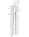
- the contact unit 2 has a socket 20 formed in a cylindrical shape by a conductive metal material.
- the inner diameter of the socket 20 is formed to be slightly larger than the outer diameter of the contacter 10. Then, a base end side portion of the contactor 10, specifically, a lower portion of the tubular body 11 is inserted into the socket 20 and is held.
- the socket 20 has a C-shaped shape when viewed in cross section from the axial direction.
- the C-shaped cut 21a of the socket 20 extends along the longitudinal direction of the socket 20.
- the cut 21a is a gap that is inevitably formed on the peripheral wall of the socket 20 when the rectangular socket component is curved into a cylindrical shape to form the socket 20, as will be described later.
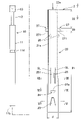
- the socket 20 is provided between the socket body 21 inserted into the accommodating hole 30 of the base plate 3, the tip side portion 22 inserted into the hole 50 of the cover plate 4, and the socket body 21 and the tip side portion 22. It has an intermediate portion 29 and the like.
- the first terminal spring 23, the contact stopper 24, the holding portion 25, and the bulging portion 26 are located on the lower side of FIG. 4 on the base end side of the socket main body 21. It is provided in order from.
- the first terminal spring 23 is a cantilever-shaped leaf spring material formed by bending the upper portion of a trapezoidal notch formed in the socket main body 21 inward of the socket main body 21.
- the contact stopper 24 is formed, for example, by recessing the lower portion of the notch 24a (see FIG. 4) extending in the circumferential direction of the socket main body 21 inward in the radial direction of the socket main body 21.
- a pair of holding portions 25, 25 are provided on both sides of the cut 21a on the upper side of the contact stopper 24.
- the cut 21a is located at the center of the pair of holding portions 25, 25.
- the portion between the slits SL, SL sandwiched by the pair of slits SL, SL extending along the axial direction formed on the peripheral wall of the socket main body 21 is the holding portion 25.
- the slits SL and SL are not necessarily limited to the examples extending along the axial direction.
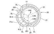
- the angle R formed by the pair of virtual lines LN1 and LN2 connecting the center of each of the pair of holding portions 25 and 25 and the axis Z of the socket 20 is substantially 120 degrees.
- substantially 120 degrees means that an error such as manufacturing variation is allowed with respect to 120 degrees.
- the angle R may be smaller than 180 degrees and is not necessarily limited to 120 degrees.
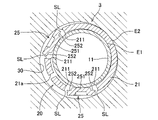
- FIG. 7 shows a state in which the holding portions 25 and 25 are in a protruding posture in which the protruding portions 251 project into the space inside the socket 20 when the tubular body 11 is not located in the socket 20.
- the holding portion 25 shown in FIG. 8 is a view seen from the axis Z side in FIG. 7.
- a protruding portion 251 projecting in the Z direction of the axial center is formed.
- the protrusion 251 is viewed from the back side, and the protrusion 251 is seen as a depression formed by press working.
- the protruding portion 251 is not necessarily limited to the example formed by press working, and the back side of the protruding portion 251 does not have to be recessed.
- the holding portion 25 includes a pair of edge portions 252 and 252 located between the protruding portion 251 and the pair of slits SL and SL.
- the holding portion 25 further includes non-protruding portions 253 and 253 which are connected to the upper and lower portions of the protruding portion 251.
- the edge portion 252 and the non-protruding portion 253 do not project radially inward from the inner circumference of the socket 20 in the protruding posture and the pressing posture described later.
- the edge portion 252 and the non-protruding portion 253 correspond to an example of the non-protruding portion.
- FIG. 9 shows a state in which the holding portions 25, 25 are in a pressing posture in which the tubular body 11 is pressed by the protruding portion 251 when the tubular body 11 is located in the socket 20.
- the holding portions 25 and 25 change their postures to a pressing posture in which the tubular body 11 is pressed by the protruding portion 251.
- the protruding portion 251 urges the tubular body 11 due to the springiness of the holding portions 25, 25 to return to the original shape.
- the amount of protrusion from the inner peripheral surface of the socket 20 in the protruding posture of the protruding portion 251 is determined. It may be larger than the difference between the inner diameter of the socket 20 and the outer diameter of the tubular body 11.
- the cylindrical body 11 is pressed against the inner wall of the socket 20 at the contact position E1 by the urging force of the protrusion 251.
- the angle formed by the virtual line LN3 and the virtual line LN1 connecting the axis Z and the center of the cut 21a, and the angle formed by the virtual line LN3 and the virtual line LN2 are both R / 2, that is, from the above 180 degrees.
- the cut 21a is located at the center of the holding portions 25 and 25 within the range of the small angle R. As a result, the contact position E1 is located on the opposite side of the cut 21a.
- the tubular body 11 is stably held at three points, the protruding portion 251 located at intervals in the circumferential direction of the socket body 21, and the contact position E1. If the angle R is substantially 120 degrees, the tubular body 11 is held at three points located at equal intervals in the circumferential direction of the socket body 21, and the stability of holding is further improved. The action of the accommodating hole 30 on the holding of the tubular body 11 will be described later.
- the tubular body 11 is held by the pressing force of the protruding portion 251, it is easy to increase the inner diameter of the socket 20 to facilitate the insertion of the contactor 10 into the socket 20. Therefore, in the contact unit 2, it is easy to achieve both the ease of inserting the contact 10 into the cylindrical socket 20 and the difficulty of removing the contact 10 from the socket 20.
- the socket 20 is liable to be distorted in the vicinity of the cut 21a, and the shape of the socket 20 is most stable on the opposite side farthest from the cut 21a. Therefore, by locating the cut 21a in the center of the holding portions 25, 25 within the range of the angle R smaller than 180 degrees, the contact position E1 is set on the opposite side of the cut 21a where the shape of the socket 20 is most stable. Can be located in.
- the tubular body 11 can be guided at the position where the shape of the socket 20 is most stable, the stability of holding the contactor 10 is improved, and the effect of reducing the positional deviation of the cup 13 can be expected to be improved. ..
- the cut 21a may be within the range of the angle R smaller than the above-mentioned 180 degrees, and the angle formed by the virtual line LN3 of the cut 21a and the virtual line LN1 of the protrusion 251 and the virtual line 21a of the cut 21a are not necessarily included.
- the angle formed by the line LN3 and the virtual line LN2 of the protrusion 251 is not limited to the same example. If the cut 21a is within the range of the angle R smaller than 180 degrees, the contact position E1 can be positioned while avoiding the cut 21a having the largest strain.
- the tubular body 11 When the tubular body 11 is held by the three protruding portions 251 as shown in FIG. 11, the tubular body 11 is held by the protruding portions 251 and does not come into contact with the inner wall of the socket 20 and floats in the air. Will be. In this state, the contactor 10 tends to tilt, and therefore the position of the cup 13 tends to move.
- the tubular body 11 is held at the three points of the protrusions 251,251 and the contact position E1.
- An example formed at the position is shown.
- the spring 23 for each first terminal and the contact stopper 24 may be formed at positions displaced in the circumferential direction in the plan view of the socket body 21.
- the intermediate portion 29 is provided with a pair of overhanging portions 27 protruding outward in the radial direction.
- the overhanging portion 27 is composed of a cut-up portion formed by, for example, expanding the upper portion of the notch extending in the circumferential direction formed on the peripheral wall of the intermediate portion 29 outward in the radial direction. Further, the lower end surface 271 of the overhanging portion 27 is formed on a horizontal plane.
- the pair of overhanging portions 27, 27 project in opposite directions with respect to the axial center Z of the socket 20.
- the distance from the axial center Z of the socket 20 to the tip of the overhanging portion 27 is formed to be larger than the distance from the axial center Z to the outer peripheral surface of the bulging portion 26.
- the base plate 3 and the cover plate 4 are formed into a plate shape having a rectangular plan view shape by an insulating member having a predetermined thickness.
- the cover plate 4 is fixed to the base plate 3 by means such as screwing.
- the base plate 3 has a facing surface FB facing the cover plate 4, and the cover plate 4 has a facing surface FC facing the base plate 3.
- the cover plate 4 is formed with a spacer portion 40 protruding from the facing surface FC.
- the facing surface FB and the facing surface FC face each other with a gap of the facing spacing P.
- the facing distance P corresponds to the protrusion height of the spacer portion 40.
- the inner diameter D of the accommodating hole 30 is formed to be slightly larger than the outer diameter d of the socket 20 shown in FIG.
- the radius D / 2 of the accommodating hole 30 and the hole 50 is smaller than the distance from the axis Z to the tip of the overhanging portion 27.
- the axial dimension T of the socket 20 of the overhanging portion 27 is smaller than the facing distance P.
- the tip end side portion 22 is inserted into the hole portion 50 of the cover plate 4 and held, and the overhanging portion 27 is located in the gap of the facing interval P.
- the number of the overhanging portions 27 is not limited to two, and may be one or three or more.
- 64 accommodation holes 30 are formed in the vertical direction of the base plate 3 extending in the vertical direction on FIG. 12. Further, for example, 64 accommodating holes 30 are formed in the lateral direction of the base plate 3 extending in the left-right direction on FIG. As a result, the base plate 3 has 4096 accommodating holes 30 arranged in a grid pattern.
- the assembly 6 of the sockets 20 includes carriers 61, 62 for transporting sockets, and a plurality of sockets 20 transported together with the carriers 61, 62.
- the upper end portion in the axial direction of the socket 20 and the carrier 61 are detachably connected by a connecting portion 63.
- a plurality of connecting portions 63 connected to each socket 20 are installed at a fixed installation interval K.
- the lower end portion in the axial direction of the socket 20 and the carrier 62 are detachably connected by a connecting portion 64.
- a plurality of connecting portions 64 connected to each socket 20 are installed at a fixed installation interval K.
- the connecting portions 63 and 64 are cut by bending the connecting portions 63 and 64, and are formed in a narrow width so that the socket 20 is separated from the carriers 61 and 62, respectively.
- the pair of overhanging portions 27 project in a direction Ls that intersects the longitudinal Lc of the carriers 61 and 62 at an angle of, for example, 45 degrees. Has been done.
- the pair of overhanging portions 27 each have about 45 with respect to the arrangement direction of the accommodating hole 30. It is configured to be tilted at an angle of degree.
- a metal plate having a predetermined thickness is punched, and as shown in FIG. 15, a pair of upper and lower carriers 61, 62 are arranged between the carriers 61 and 62.
- a punched plate 60 having a plurality of socket components 65 made of a rectangular plate-like body is formed.
- the spring 23 for the first terminal, the contact stopper 24, the slit SL, the holding portion 25, the protruding portion 251, the bulging portion 26, the overhanging portion 27, and the like are pressed at predetermined positions of the socket component 65 by press working or the like.
- an aggregate 6 of sockets 20 in which a plurality of sockets 20 are installed is formed between the upper and lower carriers 61 and 62.
- the installation interval K of the sockets 20 adjacent to each other provided in the aggregate 6 is set to, for example, an integral multiple of the arrangement interval S of the accommodation holes 30 and 30 adjacent to each other provided in the base plate 3.
- the installation spacing K of the connecting portions 63 and 64 is set to be three times the arrangement spacing S of the accommodation holes 30 and 30 arranged in the lateral direction of the base plate 3 (see FIG. 12).
- the installation interval K of the connecting portions 63 and 64 is not limited to three times the arrangement interval S of the accommodation holes 30 and 30, but may be twice, or may be four times or more the arrangement interval S. good. Further, the installation interval K of each of the connecting portions 63 and 64 may be one times the arrangement interval S of the accommodation holes 30 and 30, that is, the installation interval K and the arrangement interval S may be equal to each other.
- the user In order to assemble the contact unit 2 and the connector 1 using the assembly 6 of the socket 20, the user first first installs the upper end of the connecting portion 64 provided between the lower carrier 62 and the base end portion of the socket 20. By bending and cutting the portion, as shown in FIG. 16, the lower carrier 62 is separated from the base end portion of the socket 20.
- each socket 20 connected only to the upper carrier 61 as described above is opposed to, for example, the upper end opening of the accommodation holes 30 arranged laterally of the base plate 3.
- the socket main bodies 21 of the plurality of sockets 20 are inserted into the accommodating holes 30.
- the bulging portion 26 is fitted into the accommodating hole 30, and the lower end surface 271 of the overhanging portion 27 is abutted against the facing surface FB of the base plate 3.
- the holding portion 25 is outside the outer periphery of the socket main body 21 as shown in FIG. 7, unlike FIG. Does not protrude to. Therefore, when the socket main body 21 is inserted into the accommodating hole 30, the holding portion 25 does not interfere with the inner wall of the accommodating hole 30. As a result, it is easy to smoothly insert the socket body 21 into the accommodating hole 30.
- the user disconnects the upper carrier 61 from the tip of the socket 20 by bending and cutting the lower end of the connecting portion 63.
- a plurality of sockets 20 are simultaneously accommodated in a horizontal row in every other accommodation hole 30.
- the socket 20 is contained in all the accommodating holes 30 of the base plate 3. Will be housed and held.
- the pair of overhanging portions 27 provided in each socket 20 are arranged in a state of being inclined at about 45 degrees with respect to the arrangement direction (horizontal direction) of each socket 20. That is, as shown in FIG. 14, the pair of overhanging portions 27 project from each other in the direction Ls intersecting the longitudinal direction Lc of the carriers 61 and 62 at an angle of 45 degrees. Therefore, after the user inserts the plurality of sockets 20 into the accommodating holes 30 of the base plate 3, the tip of each socket 20 is separated from the carrier 61, so that the installation direction of the pair of overhanging portions 27 and the accommodating holes 30 are obtained. Is in a state of intersecting with the arrangement direction of the above at an angle of about 45 degrees.
- the base end side portion of the contactor 10 shown in FIG. 2 is inserted into the socket 20 from the tip opening 22a, and the bottom wall 11b of the contactor 10 is abutted against the contactor stopper 24 of the socket body 21.
- the protruding portion 251 of the holding portion 25 is pressed against the outer peripheral surface of the contactor 10, and the contactor unit 2 in which the contactor 10 and the socket 20 are electrically connected is assembled.
- the holding portions 25, 25 When the holding portions 25, 25 are pushed outward in the radial direction, the holding portions 25, 25 interfere with the inner wall of the accommodating hole 30, and the holding portions 25, 25 are pushed back by the inner wall of the accommodating hole 30 due to the reaction force.
- the tubular body 11 is pressed against the inner wall of the socket body 21 at the contact position E1.
- the socket body 21 is pushed outward in the radial direction by the tubular body 11 at the contact position E1, and the outer wall of the socket body 21 is pressed against the inner wall of the accommodating hole 30 at the contact position E2.
- the socket main body 21 is held in contact with and interferes with the inner wall of the accommodating hole 30 at three locations of the holding portions 25 and 25 and the contact position E2, and as a result, the socket 20 is difficult to come out of the accommodating hole 30. ..
- the tubular body 11 also contacts and interferes with the inner wall of the socket main body 21 at three points of the holding portions 25 and 25 and the contact position E1, and as a result, the contactor 10 comes from the socket 20. It becomes difficult to pull out.
- the socket body 21 that is, the socket 20 being pressed against the contact position E2 of the inner wall of the accommodation hole 30 by the holding portions 25, 25, the inner wall of the accommodation hole 30 functions as a guide for supporting the socket 20 as shown in FIG. do.
- the socket 20 is stably held, and the possibility that the position of the cup 13 is shaken is reduced.
- the socket 20 when the tubular body 11 is held by the three protrusions 251 the socket 20 is also held by the three protrusions 251. In this case, the socket 20 does not come into contact with the inner wall of the accommodating hole 30, and is in a state of floating in the air. In this state, the socket 20 tends to tilt, and therefore the position of the cup 13 tends to move.
- the configuration in which the tubular body 11 and the socket 20 are held at the three points of the protrusions 251,251 and the contact position E1 is more preferable than the configuration in which the tubular body 11 and the socket 20 are held by the three protrusions 251.
- the holding portion 25 does not necessarily have to include a pair of edge portions 252, and the holding portion 25 may have only one edge portion 252. Further, the holding portion 25 does not have an edge portion 252, and both ends of the protruding portion 251a may reach the slits SL, SL, as in the holding portion 25a shown in FIG. 20, for example.
- the holding portion 25 includes an edge portion 252.
- FIG. 21 shows the protruding posture of the holding portion 25a.
- FIG. 22 shows the pressing posture of the holding portion 25a.
- the holding portion 25a having no edge portion 252 is pressed outward in the radial direction by the peripheral surface of the tubular body 11.
- the interference portion H the corner portions 254 and 254 on the outer diameter side of the protrusion 251a are likely to be caught on the corner portions 211 and 211 on the inner diameter side facing the slits SL and SL of the socket main body 21.
- the pressing force from the tubular body 11 is received by the socket body 21 and acts as a force to deform the peripheral wall of the socket body 21 so as to expand it. In other words, the pressing force escapes.
- the reaction force generated in the protruding portion 251a is weakened against the pressing force from the tubular body 11, and the contact pressure between the protruding portion 251a and the tubular body 11 is weakened, so that the contactor 10 is difficult to be removed from the socket 20. Holding power decreases.
- the inner diameter of the socket body 21 In order to reduce the release of pressing force due to the deformation of the socket body 21, it is conceivable to reduce the inner diameter of the socket body 21. However, if the inner diameter of the socket body 21 is reduced, the difference between the inner diameter of the socket 20 and the inner diameter of the contactor 10 becomes smaller, and the difficulty of inserting the contactor 10 into the socket 20 increases.
- the holding portion 25 having the edge portion 252 has an increased holding force of the contactor 10 by the socket 20 and is easier to insert the contactor 10 into the socket 20 than the holding portion 25a having no edge portion 252. It becomes easy to achieve both.
- the holding portion 25 including the edge portion 252 As shown in FIG. 19, even if the holding portion 25 is pushed outward in the radial direction by the pressing force from the tubular body 11, the holding portion 25 protrudes by the edge portions 252 and 252. As a result of the portions 251 and the corner portions 211 and 211 being separated from each other, the corner portions 211 and 211 and the protruding portions 251 do not interfere with each other. As a result, the pressing force from the tubular body 11 does not escape to the socket body 21, and it is easy to maintain the holding force that makes it difficult for the contactor 10 to come off from the socket 20.
- the corner portions 211 and 211 and the protruding portion 251 do not interfere with each other, it is easy to increase the stroke in which the protruding portion 251 protrudes in the outer diameter direction so that the protruding portion 251 interferes with the inner wall of the accommodating hole 30. .. If the protrusion 251 can interfere with the inner wall of the accommodating hole 30, as described above, the reaction force generated on the inner wall of the accommodating hole 30 makes it difficult for the socket 20 to come out of the accommodating hole 30, and the contact 10 is removed from the socket 20. It becomes easy to make it difficult to pull out.
- the contact pressure between the inner wall of the accommodating hole 30 and the protruding portion 251 can be adjusted by adjusting the inner diameter of the accommodating hole 30. Therefore, by adjusting the inner diameter of the accommodating hole 30, it becomes easy to adjust the holding force that makes it difficult for the socket 20 to come out of the accommodating hole 30 and the holding force that makes it difficult for the contactor 10 to come out of the socket 20.
- the connector 1 when the socket 20 is accommodated in the accommodating hole 30 of the base plate 3 and the contactor 10 is not located in the socket 20, the projecting portion 251 of the holding portion 25 projects into the socket 20. It has become.
- the protruding portion 251 interferes with the tubular body 11, the protruding portion 251 is pushed in the outer diameter direction of the socket 20, and the holding portion 25 is the socket 20.
- the holding portion 25 is pressed against the inner wall of the accommodating hole 30 of the base plate 3 so as to protrude from the outer periphery of the base plate 3. As a result, it is easy to prevent the socket 20 from coming off from the base plate 3.
- reaction force generated by the holding portion 25 being pressed against the inner wall of the accommodating hole 30 acts as a force for pressing the protruding portion 25 against the tubular body 11, and as a result, the force with which the socket 20 holds the contactor 10. Is easy to increase.
- the diameter of the socket 20 tends to expand, so that the holding force of the contact 10 by the socket 20 tends to decrease.
- the protrusion 25 presses the inner wall of the accommodating hole 30, and the reaction force thereof presses and holds the contactor 10, so that the socket 20 has a C-shaped cross section. Even so, it is easy to increase the holding force of the contactor 10.
- the protruding portion 25 is made of the socket 20 by the tubular body 11.
- the possibility that the edges of the edge portions 252,252 and the non-projecting portions 253, 253 are caught by the corner portions 211 of the slit SL is reduced, and the holding portion 25 easily protrudes from the outer periphery of the socket 20. ..
- the holding portion 25a shown in FIG. 20 is also provided with the non-protruding portion 253, so that the entire holding portion does not have the non-protruding portion 253 and the entire holding portion protrudes inward from the inner peripheral surface of the socket 20. It is possible to reduce the possibility that the portions 211 and 211 and the holding portion interfere with each other.
- the socket 20 is inserted into the accommodating hole 30, and the contactor 10 is inserted into the socket 20, so that the contactor unit 2 is held by the base plate 3. Further, the cover plate 4 is installed so as to cover the tip end portion of the contactor unit 2 and is fixed to the base plate 3. As a result, the connector 1 shown in FIG. 1 is assembled.
- a cut 21a extending in the longitudinal direction of the socket 20 is formed on the peripheral wall of the socket 20 and the socket 20 has a C-shaped shape in a cross-sectional view seen from the axial direction. May be configured as a socket.
- the diameter of the socket 20 is extremely small, it is not possible to form the above-mentioned first terminal spring 23, contact stopper 24, holding portion 25, bulging portion 26, and overhanging portion 27 in the socket made of a pipe material. Not easy.
- the socket 20 is formed by bending the plate-shaped socket component into a cylindrical shape. It can be easily formed. Moreover, before the plate-shaped socket component is rolled to form the socket 20, a part of the socket component is pressed, so that the bulge 26, the overhang 27, the holding portions 25, 25a, and the contact are made. The child stopper 24, the spring 23 for the first terminal, and the like can be easily formed. Therefore, the socket 20 provided with the cut 21a is more preferable in that it is easy to manufacture.
- the user can insert the socket 20 into the accommodating hole 30 of the base plate 3.
- the work of accommodating can be easily performed. That is, the socket body 21 of each socket 20 whose upper end is connected to the carrier is inserted into the accommodating holes 30, and then the upper carrier 61 is separated from the tip of the socket 20 to enter the plurality of accommodating holes 30. Can accommodate the socket 20 at the same time.
- the installation spacing K (see FIG. 13) of the connecting portions 63 and 64 provided on the carriers 61 and 62 is an integral multiple of the arrangement spacing S (see FIG. 12) of the phase-adjacent accommodating holes 30 arranged in the base plate 3. Since it is set to, a plurality of sockets 20 can be accommodated in the accommodating hole 30 at the same time in a row. It should be noted that the lower carrier 62 and the connecting portion 64 are omitted, and an aggregate of comb-shaped sockets 20 in which the upper end portion of the socket 20 is detachably connected by a plurality of connecting portions 63 provided on the upper carrier 61 is formed. It can also be used.
- the pair of overhanging portions 27 can be installed in a state of being inclined at a constant angle with respect to the arrangement direction of the accommodating holes 30. can. As a result, it is easier to prevent interference between the adjacent overhanging portions 27 as compared with the case where the pair of overhanging portions 27 are installed so as to be along the horizontal direction or the vertical direction of the base plate 3. Therefore, it is easy to secure a sufficient amount of protrusion of the overhanging portion 27.
- the protruding direction Ls of the pair of overhanging portions 27 provided in the socket 20 is directed parallel to the longitudinal direction Lc of the carriers 61 and 62.
- the installation spacing K1 of the connecting portions 63 and 64 provided on the carriers 61 and 62 is an integer of the arrangement spacing S1 of the phase-adjacent accommodation holes 30 arranged diagonally in the base plate 3. It is preferably set to double.
- the user inserts the lower portion of the socket 20 into each accommodation hole 30 and accommodates the carrier 61, 62 in a state where the carriers 61 and 62 are arranged along the accommodation holes 30 arranged diagonally in the base plate 3.
- the pair of overhanging portions 27 will be installed in a state of being inclined in the diagonal direction of the base plate 3.
- the installation intervals K and K1 do not necessarily have to be integral multiples of the arrangement intervals S and S1.
- the cover plate 4a shown in FIG. 3 is formed with a through hole 5 externally fitted to the tip end portion of the contactor unit 2.
- the through hole 5 includes a first hole portion 51, a second hole portion 52, a third hole portion 53, and a fourth hole portion 54 formed at positions overlapping with the accommodating hole 30 of the base plate 3 in a plan view. It is a connected hole.
- the inner diameter of the first hole 51 located at the lowermost of the holes 51 to 54 provided in the cover plate 4a is formed to be larger than the outer diameter d of the socket 20. As a result, the tip portion of the socket 20 can be inserted into the first hole portion 51.
- a second hole portion 52 having an inner diameter substantially the same as the outer diameter of the tubular body 11 of the contactor 10 is provided.
- a third hole portion 53 having an inner diameter larger than the outer diameter of the plungers 12a and 12b of the contactor 10 is formed.
- a plunger 12a or a plunger 12b can be inserted into the third hole 53.
- a fourth hole portion 54 having an inner diameter larger than the inner diameter of the third hole portion 53 and slightly larger than the outer diameter of the above-mentioned second terminal B is formed. ..
- the tip end portion of the plunger 12 and the second terminal B are inserted into the fourth hole portion 54 so as to be electrically connected to each other.
- the socket 20 is prevented from coming out from the cover plate 4a side due to the step between the first hole 51 and the second hole 52, and the socket 20 comes into contact with the second hole 52 and the third hole 53. It is prevented that the child 10 comes out from the cover plate 4a side. Further, the third hole portion 53 and the fourth hole portion 54 can improve the positioning accuracy between the plungers 12a and 12b and the second terminal B.
- the connector according to an example of the present invention has a cylindrical socket, a rod-shaped connector, and a contact having a first portion that can be located in the socket and a second portion that protrudes from one end of the socket.
- a holding member having an accommodating hole for accommodating the socket, and a pair of slits extending in parallel with each other are formed on the peripheral wall of the socket, and the holding portion is a portion sandwiched by the pair of slits.
- the protruding posture is such that the non-protruding portion does not protrude radially inward from the inner circumference of the socket in the protruding posture.
- the socket is accommodated in the accommodating hole of the holding member, and when the contactor is not located in the socket, the protruding portion of the holding portion is in a protruding posture in which it protrudes into the socket.
- the protrusion interferes with the contact, the protrusion is pushed in the outer diameter direction of the socket, the holding portion protrudes from the outer circumference of the socket, and the holding portion is a holding member. It is pressed against the inner wall of the accommodating hole. As a result, it is easy to prevent the socket from coming off from the holding member.
- the reaction force generated by pressing the holding portion against the inner wall of the accommodating hole acts as a force for pressing the protruding portion against the contact, and as a result, it is easy to increase the force for the socket to hold the contact. ..
- the non-projecting portion of the holding portion does not project radially inward from the inner circumference of the socket in the protruding posture, the edge of the non-projecting portion is pushed by the contactor in the outer diameter direction of the socket. Is reduced from being caught on the edge of the slit, and the holding portion is easily projected from the outer periphery of the socket.
- the holding portion can change its posture to a pressing posture in which the first portion is pressed by the protruding portion.
- the holding portion changes its posture to the pressing posture, and the first portion is pressed by the protruding portion. Therefore, it is easy to hold the contact.
- the protrusion amount of the protrusion is larger than the difference between the inner diameter of the socket and the outer diameter of the first portion.
- the holding portion when the first portion is located in the socket, the holding portion can be changed to the pressing posture.
- the holding portion includes, as the non-projecting portion, an edge portion located between the protruding portion and the pair of slits.
- the protruding portion is moved away from the edge of the slit by the edge portion, so that the possibility that the protruding portion is caught on the edge of the slit when the holding portion changes from the protruding posture to the pressing posture is reduced.
- the pair of slits extend along the axial direction of the socket.
- the angle formed by the pair of virtual lines having the pair of holding portions and connecting the pair of holding portions and the axis of the socket is smaller than 180 degrees.
- the contact can be pressed against the inner wall of the socket by the pair of holding portions.
- the contact can be supported at three points by the contact position where the contact contacts the inner wall of the socket and the pair of holding portions, it becomes easy to stably hold the contact. Further, since the inner wall of the socket guides the contacts, the shake of the contacts is reduced.
- the angle formed by the pair of virtual lines connecting the pair of holding portions and the axis of the socket is substantially 120 degrees.
- the contact position where the contactor contacts the inner wall of the socket and the position of the pair of holding portions are divided into three equal parts, so that the contactor can be stably supported at three points. ..
- the socket has a C-shaped shape in a cross-sectional view seen from the axial direction.
- the socket has a C-shaped shape in a cross-sectional view seen from the axial direction, and the cut of the C-shaped shape is located within an angle range smaller than 180 degrees.
- a socket with a C-shaped cross section is prone to distortion near the cut. Therefore, by locating the cut within an angle range smaller than 180 degrees, the contactor can be brought into contact with the inner wall of the socket, avoiding the vicinity of the cut where strain is likely to occur.
- the C-shaped cut is located substantially at the center of the pair of holding portions within a range of an angle smaller than 180 degrees.
- a socket with a C-shaped cross section is prone to distortion near the cut, and the shape of the socket is the most stable on the opposite side farthest from the cut. Therefore, by locating the cut approximately in the center of the pair of holdings within an angle range smaller than 180 degrees, the contactor can be brought into contact with the inner wall of the socket on the opposite side of the cut where the shape of the socket is most stable. can.
- the aggregate of sockets is an aggregate of the sockets in the above-mentioned connector, and includes a carrier for transporting the socket and a plurality of the sockets transported together with the carrier.
- the carrier is provided with a plurality of connecting portions in which the axial end portions of the socket are detachably connected to each other at regular intervals.
- the user inserts the other end of each socket into the accommodating hole using a collection of sockets in which one end of each socket is connected to the carrier, and then the carrier is removed from one end of the socket.
- the socket can be accommodated in a plurality of accommodating holes at the same time. Therefore, it is easy to insert the socket body into the accommodating hole and accommodate it in the holding member.
- the connector having such a configuration and the aggregate of the sockets constituting the socket make it difficult for the socket to come off from the holding member that holds the socket, and it is easy for the socket to increase the force for holding the contact.
Landscapes
- Connecting Device With Holders (AREA)
- Connector Housings Or Holding Contact Members (AREA)
Priority Applications (3)
| Application Number | Priority Date | Filing Date | Title |
|---|---|---|---|
| CN202180087566.0A CN116783782A (zh) | 2020-12-28 | 2021-11-10 | 连接器、以及插座集合体 |
| JP2022572929A JPWO2022145134A1 (https=) | 2020-12-28 | 2021-11-10 | |
| KR1020237025389A KR20230124066A (ko) | 2020-12-28 | 2021-11-10 | 커넥터, 소켓 및 소켓의 집합체 |
Applications Claiming Priority (2)
| Application Number | Priority Date | Filing Date | Title |
|---|---|---|---|
| JP2020219348 | 2020-12-28 | ||
| JP2020-219348 | 2020-12-28 |
Publications (1)
| Publication Number | Publication Date |
|---|---|
| WO2022145134A1 true WO2022145134A1 (ja) | 2022-07-07 |
Family
ID=82260406
Family Applications (1)
| Application Number | Title | Priority Date | Filing Date |
|---|---|---|---|
| PCT/JP2021/041382 Ceased WO2022145134A1 (ja) | 2020-12-28 | 2021-11-10 | コネクタ、及びソケットの集合体 |
Country Status (5)
| Country | Link |
|---|---|
| JP (1) | JPWO2022145134A1 (https=) |
| KR (1) | KR20230124066A (https=) |
| CN (1) | CN116783782A (https=) |
| TW (1) | TW202245361A (https=) |
| WO (1) | WO2022145134A1 (https=) |
Citations (4)
| Publication number | Priority date | Publication date | Assignee | Title |
|---|---|---|---|---|
| JPS642181U (https=) * | 1987-06-22 | 1989-01-09 | ||
| JP2019061871A (ja) * | 2017-09-27 | 2019-04-18 | 日本電産リード株式会社 | 多極コネクタ |
| JP2019087507A (ja) * | 2017-11-10 | 2019-06-06 | 株式会社エンプラス | 接触部材及び電気部品用ソケット |
| JP2020161472A (ja) * | 2019-03-22 | 2020-10-01 | 日本電産リード株式会社 | 接触子ユニット、これを構成するソケットの集合体、及び接触子ユニットを備えた多極コネクタ |
Family Cites Families (1)
| Publication number | Priority date | Publication date | Assignee | Title |
|---|---|---|---|---|
| US5399104A (en) | 1992-09-28 | 1995-03-21 | Mckenzie Socket Technology, Inc. | Socket for multi-lead integrated circuit packages |
-
2021
- 2021-11-10 KR KR1020237025389A patent/KR20230124066A/ko active Pending
- 2021-11-10 CN CN202180087566.0A patent/CN116783782A/zh active Pending
- 2021-11-10 WO PCT/JP2021/041382 patent/WO2022145134A1/ja not_active Ceased
- 2021-11-10 JP JP2022572929A patent/JPWO2022145134A1/ja active Pending
- 2021-12-27 TW TW110148939A patent/TW202245361A/zh unknown
Patent Citations (4)
| Publication number | Priority date | Publication date | Assignee | Title |
|---|---|---|---|---|
| JPS642181U (https=) * | 1987-06-22 | 1989-01-09 | ||
| JP2019061871A (ja) * | 2017-09-27 | 2019-04-18 | 日本電産リード株式会社 | 多極コネクタ |
| JP2019087507A (ja) * | 2017-11-10 | 2019-06-06 | 株式会社エンプラス | 接触部材及び電気部品用ソケット |
| JP2020161472A (ja) * | 2019-03-22 | 2020-10-01 | 日本電産リード株式会社 | 接触子ユニット、これを構成するソケットの集合体、及び接触子ユニットを備えた多極コネクタ |
Also Published As
| Publication number | Publication date |
|---|---|
| TW202245361A (zh) | 2022-11-16 |
| KR20230124066A (ko) | 2023-08-24 |
| JPWO2022145134A1 (https=) | 2022-07-07 |
| CN116783782A (zh) | 2023-09-19 |
Similar Documents
| Publication | Publication Date | Title |
|---|---|---|
| JP6041107B2 (ja) | フローティング機構付き同軸コネクタ | |
| JP2020161472A (ja) | 接触子ユニット、これを構成するソケットの集合体、及び接触子ユニットを備えた多極コネクタ | |
| JP2020087837A (ja) | コネクタ | |
| KR20190002329A (ko) | 커넥터 단자 어셈블리 | |
| KR101628896B1 (ko) | 동축 커넥터 | |
| EP3637555B1 (en) | Connector | |
| JP6766752B2 (ja) | 端子モジュール | |
| JP2019061871A (ja) | 多極コネクタ | |
| JP6477660B2 (ja) | 基板対基板コネクタ | |
| WO2020105525A1 (ja) | プローブ | |
| WO2022145134A1 (ja) | コネクタ、及びソケットの集合体 | |
| JP7548299B2 (ja) | 接触子ユニット、ソケットの集合体、及びコネクタ | |
| JP5881891B2 (ja) | 電子部品の組付構造及び電気接続箱 | |
| JP6317557B2 (ja) | 取付部材および電気部品用ソケット | |
| CN117855977A (zh) | 带浮动机构的连接器 | |
| EP3588691B1 (en) | Connector | |
| JP6414018B2 (ja) | 電池用バスバー | |
| CN111725649B (zh) | 插座、接触件单元、插座的聚集体、及多极连接器 | |
| JP5563911B2 (ja) | 電気部品用ソケット | |
| JP2025008372A (ja) | コネクタ | |
| JP2020198323A (ja) | 端子モジュール | |
| EP2919327B1 (en) | Contact and method for mounting such contact |
Legal Events
| Date | Code | Title | Description |
|---|---|---|---|
| 121 | Ep: the epo has been informed by wipo that ep was designated in this application |
Ref document number: 21914995 Country of ref document: EP Kind code of ref document: A1 |
|
| ENP | Entry into the national phase |
Ref document number: 2022572929 Country of ref document: JP Kind code of ref document: A |
|
| WWE | Wipo information: entry into national phase |
Ref document number: 202180087566.0 Country of ref document: CN |
|
| ENP | Entry into the national phase |
Ref document number: 20237025389 Country of ref document: KR Kind code of ref document: A |
|
| NENP | Non-entry into the national phase |
Ref country code: DE |
|
| 122 | Ep: pct application non-entry in european phase |
Ref document number: 21914995 Country of ref document: EP Kind code of ref document: A1 |