WO2022138340A1 - 安心ビジョン装置、及び安心ビジョンシステム - Google Patents
安心ビジョン装置、及び安心ビジョンシステム Download PDFInfo
- Publication number
- WO2022138340A1 WO2022138340A1 PCT/JP2021/046118 JP2021046118W WO2022138340A1 WO 2022138340 A1 WO2022138340 A1 WO 2022138340A1 JP 2021046118 W JP2021046118 W JP 2021046118W WO 2022138340 A1 WO2022138340 A1 WO 2022138340A1
- Authority
- WO
- WIPO (PCT)
- Prior art keywords
- robot
- dimensional
- estimation model
- camera
- joint
- Prior art date
- Legal status (The legal status is an assumption and is not a legal conclusion. Google has not performed a legal analysis and makes no representation as to the accuracy of the status listed.)
- Ceased
Links
Images




Classifications
-
- B—PERFORMING OPERATIONS; TRANSPORTING
- B25—HAND TOOLS; PORTABLE POWER-DRIVEN TOOLS; MANIPULATORS
- B25J—MANIPULATORS; CHAMBERS PROVIDED WITH MANIPULATION DEVICES
- B25J19/00—Accessories fitted to manipulators, e.g. for monitoring, for viewing; Safety devices combined with or specially adapted for use in connection with manipulators
- B25J19/06—Safety devices
- B25J19/061—Safety devices with audible signals
-
- B—PERFORMING OPERATIONS; TRANSPORTING
- B25—HAND TOOLS; PORTABLE POWER-DRIVEN TOOLS; MANIPULATORS
- B25J—MANIPULATORS; CHAMBERS PROVIDED WITH MANIPULATION DEVICES
- B25J9/00—Program-controlled manipulators
- B25J9/16—Program controls
- B25J9/1694—Program controls characterised by use of sensors other than normal servo-feedback from position, speed or acceleration sensors, perception control, multi-sensor controlled systems, sensor fusion
- B25J9/1697—Vision controlled systems
-
- B—PERFORMING OPERATIONS; TRANSPORTING
- B25—HAND TOOLS; PORTABLE POWER-DRIVEN TOOLS; MANIPULATORS
- B25J—MANIPULATORS; CHAMBERS PROVIDED WITH MANIPULATION DEVICES
- B25J9/00—Program-controlled manipulators
- B25J9/16—Program controls
- B25J9/1674—Program controls characterised by safety, monitoring, diagnostic
- B25J9/1676—Avoiding collision or forbidden zones
-
- G—PHYSICS
- G06—COMPUTING OR CALCULATING; COUNTING
- G06T—IMAGE DATA PROCESSING OR GENERATION, IN GENERAL
- G06T7/00—Image analysis
- G06T7/20—Analysis of motion
- G06T7/246—Analysis of motion using feature-based methods, e.g. the tracking of corners or segments
- G06T7/251—Analysis of motion using feature-based methods, e.g. the tracking of corners or segments involving models
-
- G—PHYSICS
- G06—COMPUTING OR CALCULATING; COUNTING
- G06T—IMAGE DATA PROCESSING OR GENERATION, IN GENERAL
- G06T7/00—Image analysis
- G06T7/60—Analysis of geometric attributes
- G06T7/62—Analysis of geometric attributes of area, perimeter, diameter or volume
-
- G—PHYSICS
- G06—COMPUTING OR CALCULATING; COUNTING
- G06T—IMAGE DATA PROCESSING OR GENERATION, IN GENERAL
- G06T7/00—Image analysis
- G06T7/80—Analysis of captured images to determine intrinsic or extrinsic camera parameters, i.e. camera calibration
-
- F—MECHANICAL ENGINEERING; LIGHTING; HEATING; WEAPONS; BLASTING
- F16—ENGINEERING ELEMENTS AND UNITS; GENERAL MEASURES FOR PRODUCING AND MAINTAINING EFFECTIVE FUNCTIONING OF MACHINES OR INSTALLATIONS; THERMAL INSULATION IN GENERAL
- F16P—SAFETY DEVICES IN GENERAL; SAFETY DEVICES FOR PRESSES
- F16P3/00—Safety devices acting in conjunction with the control or operation of a machine; Control arrangements requiring the simultaneous use of two or more parts of the body
- F16P3/12—Safety devices acting in conjunction with the control or operation of a machine; Control arrangements requiring the simultaneous use of two or more parts of the body with means, e.g. feelers, which in case of the presence of a body part of a person in or near the danger zone influence the control or operation of the machine
- F16P3/14—Safety devices acting in conjunction with the control or operation of a machine; Control arrangements requiring the simultaneous use of two or more parts of the body with means, e.g. feelers, which in case of the presence of a body part of a person in or near the danger zone influence the control or operation of the machine the means being photocells or other devices sensitive without mechanical contact
- F16P3/142—Safety devices acting in conjunction with the control or operation of a machine; Control arrangements requiring the simultaneous use of two or more parts of the body with means, e.g. feelers, which in case of the presence of a body part of a person in or near the danger zone influence the control or operation of the machine the means being photocells or other devices sensitive without mechanical contact using image capturing devices
-
- G—PHYSICS
- G05—CONTROLLING; REGULATING
- G05B—CONTROL OR REGULATING SYSTEMS IN GENERAL; FUNCTIONAL ELEMENTS OF SUCH SYSTEMS; MONITORING OR TESTING ARRANGEMENTS FOR SUCH SYSTEMS OR ELEMENTS
- G05B2219/00—Program-control systems
- G05B2219/30—Nc systems
- G05B2219/39—Robotics, robotics to robotics hand
- G05B2219/39082—Collision, real time collision avoidance
-
- G—PHYSICS
- G05—CONTROLLING; REGULATING
- G05B—CONTROL OR REGULATING SYSTEMS IN GENERAL; FUNCTIONAL ELEMENTS OF SUCH SYSTEMS; MONITORING OR TESTING ARRANGEMENTS FOR SUCH SYSTEMS OR ELEMENTS
- G05B2219/00—Program-control systems
- G05B2219/30—Nc systems
- G05B2219/39—Robotics, robotics to robotics hand
- G05B2219/39098—Estimate stop, brake distance in predef time, then verify if in safe distance
-
- G—PHYSICS
- G05—CONTROLLING; REGULATING
- G05B—CONTROL OR REGULATING SYSTEMS IN GENERAL; FUNCTIONAL ELEMENTS OF SUCH SYSTEMS; MONITORING OR TESTING ARRANGEMENTS FOR SUCH SYSTEMS OR ELEMENTS
- G05B2219/00—Program-control systems
- G05B2219/30—Nc systems
- G05B2219/40—Robotics, robotics mapping to robotics vision
- G05B2219/40202—Human robot coexistence
-
- G—PHYSICS
- G06—COMPUTING OR CALCULATING; COUNTING
- G06T—IMAGE DATA PROCESSING OR GENERATION, IN GENERAL
- G06T2207/00—Indexing scheme for image analysis or image enhancement
- G06T2207/30—Subject of image; Context of image processing
- G06T2207/30196—Human being; Person
Definitions
- the present invention relates to a safety vision device and a safety vision system.
- an area sensor or the like is used to detect that an operator has invaded the operating area of the robot.
- the area sensor needs to be installed near the robot, the movement and movement of the operator and the robot are restricted.
- One aspect of the safety vision device of the present disclosure is a human three-dimensional skeleton estimation model that inputs a two-dimensional image of a human and outputs three-dimensional joint point data indicating the three-dimensional coordinate values of the positions of the human joint points.
- the robot 3D which inputs the 2D image of the robot and the distance and inclination between the camera that captured the 2D image of the robot and the robot, and outputs the angles of a plurality of joint axes included in the robot.
- the input two-dimensional image and the distance and inclination between the external camera and the robot are input to the human three-dimensional skeleton estimation model and the robot three-dimensional skeleton estimation model, and the joint of the worker.
- An estimation unit that estimates three-dimensional joint point data indicating three-dimensional coordinate values of point positions, angles of a plurality of joint axes included in the robot, and the three-dimensional joint point data and the plurality of joint axes.
- a region indicating the range of the worker and a region indicating the range of the robot are calculated based on the angle, and deceleration or deceleration with respect to the robot is performed according to the degree of overlap between the calculated region of the worker and the region of the robot. It is provided with an approach determination unit that outputs a stop instruction.
- One aspect of the safety vision system of the present disclosure includes a robot, a camera, and the safety vision device of (1).
- the robot when an operator invades the operating area of the robot without using the area sensor, the robot can be decelerated or stopped.
- FIG. 1 is a functional block diagram showing a functional configuration example of a safety vision system according to an embodiment.
- the safety vision system 1 includes a robot 10, a safety vision device 20, and a camera 40.
- the robot 10, the safety vision device 20, and the camera 40 as an external camera are illustrated by a wireless LAN (Local Area Network), Wi-Fi (registered trademark), and a mobile phone network compliant with standards such as 4G and 5G. May not be connected to each other via a network.
- the robot 10, the safety vision device 20, and the camera 40 include a communication unit (not shown) for communicating with each other by such a connection.
- a communication unit not shown
- data is transmitted and received via a robot control device (not shown) that controls the operation of the robot 10. You may do so.
- the robot 10 is, for example, an industrial robot known to those skilled in the art, and is arranged on each of a plurality of joint axes (not shown) included in the robot 10 based on a drive command from a robot control device (not shown). By driving a servomotor (not shown), a movable member (not shown) of the robot 10 is driven.
- the robot 10 will be described as a 6-axis vertical articulated robot having 6 articulated axes J1 to J6, but a vertical articulated robot other than the 6-axis robot may be used, such as a horizontal articulated robot or a parallel link robot. But it may be.
- the camera 40 as an external camera is, for example, a digital camera or the like, and is used in a factory or the like where the robot 10 is arranged so that a worker U who is a user carrying the robot 10 and the safety vision device 20 described later can be photographed. It is fixed to a wall or pillar and installed.
- the camera 40 may be a camera mounted on a smartphone, a tablet terminal, an augmented reality (AR) glass, a mixed reality (MR) glass, or the like.
- the camera 40 takes a picture of the robot 10 and the worker U at a predetermined frame rate (for example, 30 frames / sec, etc.) and projects a frame image which is a two-dimensional image projected on a plane perpendicular to the optical axis of the camera 40. Generate.
- the camera 40 outputs the generated frame image to the safety vision device 20.
- the frame image generated by the camera 40 may be a visible light image such as an RGB color image or a gray scale image. It is assumed that the robot coordinate system of the robot 10 and the camera coordinate system of the camera 40 are associated with each other in the world coordinate system by the calibration performed in advance.
- the safety vision device 20 is, for example, a smartphone, a tablet terminal, an augmented reality (AR) glass, a mixed reality (MR) glass, or the like. As shown in FIG. 1, the safety vision device 20 includes a control unit 21, a communication unit 22, and a storage unit 23. Further, the control unit 21 has a three-dimensional object recognition unit 211, a self-position estimation unit 212, an input unit 213, an estimation unit 214, an approach determination unit 215, and a notification unit 216.
- AR augmented reality
- MR mixed reality
- the communication unit 22 is a communication control device that transmits / receives data to / from a network such as a wireless LAN (Local Area Network), Wi-Fi (registered trademark), and a mobile phone network compliant with standards such as 4G and 5G.
- the communication unit 22 may communicate directly with the camera 40, for example, or may communicate with the robot 10 via a robot control device (not shown) that controls the operation of the robot 10.
- the storage unit 23 is, for example, a ROM (Read Only Memory), an HDD (Hard Disk Drive), or the like, and stores a system program and a secure vision application program executed by the control unit 21, which will be described later. Further, the storage unit 23 includes a robot 3D skeleton estimation model 232 composed of a human 3D skeleton estimation model 231 described later, a 2D skeleton estimation model 2321 described later, and a joint angle estimation model 2322, and 3D recognition model data. 233 and may be stored.
- the human 3D skeleton estimation model 231 is, for example, a known 3D pose estimation method (for example, https://engineer.dena.com/posts/2019.12/cv-papers-19-3d-human-pose-estimation/). Based on the deep learning model used for, etc., a frame image of a video of any person obtained from a data set such as Human 3.6M (http://vision.imar.ro/human3.6m/description.php). A machine learning device (not shown) using the input data of the 3D joint point data and the label data of the 3D joint point data indicating the 3D coordinate values of the joint point positions of any person annotated in advance in the frame image. Is a trained model generated by performing supervised learning.
- the robot three-dimensional skeleton estimation model 232 is composed of a two-dimensional skeleton estimation model 2321 and a joint angle estimation model 2322.
- FIG. 2 is a diagram showing an example of the relationship between the two-dimensional skeleton estimation model 2321 as the robot three-dimensional skeleton estimation model 232 and the joint angle estimation model 2322.
- the two-dimensional skeleton estimation model 2321 inputs a frame image of the robot 10 taken by the camera 40, and has pixel coordinates indicating the positions of the centers of the joint axes J1 to J6 of the robot 10 in the frame image. It is a convolutional neural network (CNN) that outputs a two-dimensional posture.
- CNN convolutional neural network
- the two-dimensional skeleton estimation model 2321 inputs frame images of the robot 10 in various postures taken by the camera 40 based on a deep learning model used in, for example, a known markerless animal tracking tool (for example, DeepLabCut).
- a machine (not shown) using training data of data and label data of two-dimensional coordinate (pixel coordinates) values indicating the positions of the centers of joint axes J1 to J6 in the frame image when each frame image was taken. It is generated by a learning device performing supervised learning.
- the joint angle estimation model 2322 is output from the two-dimensional skeleton estimation model 2321 and the distance and inclination between the camera 40 and the robot 10, and the width of the frame image with the joint axis J1 which is the base link of the robot 10 as the origin.
- the two-dimensional posture of the pixel coordinates indicating the position of the center of the joint axes J1 to J6 of the robot 10 normalized by the height, and the angle of the joint axes J1 to J6 of the robot 10 is output, a neural network, etc. Is.
- the joint angle estimation model 2322 captures, for example, input data of a two-dimensional posture indicating the distance and inclination between the camera 40 and the robot 10 and the position of the center of the normalized joint axes J1 to J6, and a frame image.
- a machine learning device (not shown) is generated by performing supervised learning using the label data of the angles of the joint axes J1 to J6 of the robot 10 and the training data at that time. The details of the machine learning device for generating the robot 3D skeleton estimation model 232 (2D skeleton estimation model 2321 and joint angle estimation model 2322) will be described later.
- the three-dimensional recognition model data 233 changes the posture and direction of the robot 10 in advance, and three-dimensionally recognizes a feature amount such as an edge amount extracted from each of a plurality of frame images of the robot 10 taken by the camera 40.
- the 3D recognition model data 233 is the 3D coordinates of the origin of the robot coordinate system of the robot 10 in the world coordinate system when the frame image of each 3D recognition model is taken (hereinafter, also referred to as "robot origin").
- robot origin the 3D coordinates of the origin of the robot coordinate system of the robot 10 in the world coordinate system when the frame image of each 3D recognition model is taken.
- the value and the information indicating the directions of the X-axis, Y-axis, and Z-axis of the robot coordinate system in the world coordinate system may also be stored in association with the three-dimensional recognition model.
- the control unit 21 has a CPU (Central Processing Unit), a ROM, a RAM, a CMOS (Complementary Metal-Oxide-Processor) memory, and the like, and these are known to those skilled in the art, which are configured to be communicable with each other via a bus. belongs to.
- the CPU is a processor that controls the safety vision device 20 as a whole.
- the CPU reads out the system program and the safety vision application program stored in the ROM via the bus, and controls the entire safety vision device 20 according to the system program and the safety vision application program. As a result, as shown in FIG.
- the control unit 21 realizes the functions of the three-dimensional object recognition unit 211, the self-position estimation unit 212, the input unit 213, the estimation unit 214, the approach determination unit 215, and the notification unit 216. It is configured as follows. Various data such as temporary calculation data and display data are stored in the RAM. Further, the CMOS memory is backed up by a battery (not shown), and is configured as a non-volatile memory in which the storage state is maintained even when the power of the safety vision device 20 is turned off.
- the three-dimensional object recognition unit 211 acquires a frame image of the robot 10 taken by the camera 40, for example, via the communication unit 22.
- the three-dimensional object recognition unit 211 extracts a feature amount such as an edge amount from the frame image of the robot 10 taken by the camera 40, for example, by using a known method of three-dimensional coordinate recognition of the robot.
- a known method refer to, for example, "https://linx.jp/product/mvtec/halcon/feature/3d_vision.html”.
- the 3D object recognition unit 211 matches the extracted feature amount with the feature amount of the 3D recognition model stored in the 3D recognition model data 233.
- the 3D object recognition unit 211 may use, for example, the 3D coordinate value of the robot origin in the world coordinate system in the 3D recognition model having the highest degree of matching, and the X-axis and Y-axis of the robot coordinate system. Information indicating the direction of each Z-axis is acquired.
- the self-position estimation unit 212 uses, for example, a known self-position estimation method to obtain a three-dimensional coordinate value of the origin of the camera coordinate system of the camera 40 in the world coordinate system (hereinafter, also referred to as “three-dimensional coordinate value of the camera 40”). To get).
- the information acquisition unit 301 calculates the distance and inclination between the camera 40 and the robot 10 based on the acquired three-dimensional coordinate values of the camera 40 and the acquired three-dimensional coordinate values of the robot origin. Since the robot 10 and the camera 40 are fixedly arranged in the factory, the self-position estimation unit 212 sets the three-dimensional coordinate value of the robot origin in the world coordinate system and the camera when the safety vision application program is started.
- the three-dimensional coordinate value of 40, the distance between the camera 40 and the robot 10, and the inclination may be calculated only once and stored in the storage unit 23.
- the input unit 213 inputs the frame image of the worker U and the robot 10 taken by the camera 40, and the distance and inclination between the camera 40 and the robot 10 calculated by the self-position estimation unit 212.
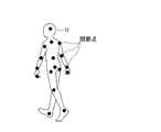
- the estimation unit 214 uses the human three-dimensional skeleton estimation model 231 and the robot 3 to capture the frame image of the worker U and the robot 10 input by the input unit 213 and the distance and inclination between the camera 40 and the robot 10. Input to the dimensional skeleton estimation model 232. Specifically, the estimation unit 214 estimates the 3D joint point data indicating the 3D coordinate value of the position of the joint point of the worker U in the input frame image from the output of the human 3D skeleton estimation model 231. .. FIG. 3 is a diagram showing an example of the position of the joint point of the worker U estimated by the estimation unit 214. As shown in FIG. 3, the joint points of the worker U estimated by the estimation unit 214 are shown by, for example, black dots.
- the estimation unit 214 estimates the angles of the joint axes J1 to J6 of the robot 10 in the input frame image from the output of the robot three-dimensional skeleton estimation model 232. As described above, the estimation unit 214 normalizes the pixel coordinates of the positions of the centers of the joint axes J1 to J6 output from the two-dimensional skeleton estimation model 2321 and inputs them to the joint angle estimation model 2322. Further, the estimation unit 214 also sets the certainty degree ci of the two-dimensional posture output from the two-dimensional skeleton estimation model 2321 to "1" when it is 0.5 or more, and "0" when it is less than 0.5. You may set it to.
- the estimation unit 214 takes a picture before the frame image and the whole of the worker U and the robot 10.
- the estimation unit 214 takes a picture before the frame image and the whole of the worker U and the robot 10.
- the robot 10 Using the time-series data of the angles of the joint axes J1 to J6 of the robot 10 estimated from a plurality of consecutive frame images in the time series, the robot 10 in the frame image in which a part of the robot 10 is hidden by the worker U.
- the angles of the joint axes J1 to J6 may be estimated.
- the approach determination unit 215 has a region indicating the range of the worker U based on the three-dimensional joint point data of the worker U estimated by the estimation unit 214 and the angles of the joint axes J1 to J6 of the robot 10, and the robot. A region indicating a range of 10 is calculated, and an instruction to decelerate or stop the robot 10 is output to a robot control device (not shown) according to the degree of overlap between the calculated region of the worker U and the region of the robot 10. .. Specifically, the approach determination unit 215 arranges the joint points of the worker U in the three-dimensional space of the world coordinate system based on the three-dimensional joint point data of the worker U estimated by the estimation unit 214, for example.
- the approach determination unit 215 calculates a region indicating the range of the worker U by fleshing out a rectangular parallelepiped or the like having a preset length, depth, and height for each straight line of the generated skeleton. Further, the approach determination unit 215 solves the forward kinematics from the angles of the joint axes J1 to J6 estimated by the estimation unit 214 using the DH (Denavit-Hartenberg) parameter table defined in advance, and the joint axes J1 to J6. Calculate the 3D coordinate value of the center position.
- DH Dens-Hartenberg
- the approach determination unit 215 arranges the calculated positions of the centers of the joint axes J1 to J6 of the robot 10 in the three-dimensional space of the world coordinate system, and generates the skeleton of the robot 10.
- the approach determination unit 215 calculates an area indicating the range of the robot 10 by fleshing it out with a shape such as a rectangular parallelepiped having a preset length, depth, and height for each link of the generated skeleton of the robot 10. ..
- the DH parameter table is created in advance based on, for example, the specifications of the robot 10 and stored in the storage unit 23.
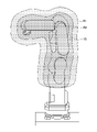
- FIG. 4 is a diagram showing an example of the area of the robot 10.
- the area of the robot 10 shown in FIG. 4 is composed of two areas R1 and areas R2 having different sizes. That is, the length, depth, and height in the region R1 are set to be larger than the length, depth, and height in the region R2.
- the approach determination unit 215 determines whether or not the area of the worker U in the calculated world coordinate system overlaps with the area R1 or the area R2 of the robot 10. When the area of the worker U overlaps only the area R1 of the robot 10, the approach determination unit 215 determines that there is time until the worker U and the robot 10 collide, and issues a deceleration command to the robot control device (illustrated).
- the approach determination unit 215 By outputting to (No), the operation of the robot 10 is slowed down.
- the approach determination unit 215 immediately determines that there is a risk of collision between the worker U and the robot 10, and issues a stop command to the robot control device (illustrated). By outputting to (No), the operation of the robot 10 is stopped. In this way, by providing the two regions R1 and R2 having different sizes as the regions of the robot 10, the approach determination unit 215 can appropriately determine whether to output a deceleration or stop instruction.
- ⁇ Notification unit 216> When the approach determination unit 215 outputs a deceleration or stop instruction, the notification unit 216 outputs a warning sound via a speaker (not shown) included in the safety vision device 20.
- the notification unit 216 may display a message indicating a warning on a display device (not shown) such as an LCD (Liquid Crystal Display) included in the safety vision device 20.
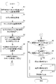
- FIG. 5 is a flowchart illustrating a determination process of the safety vision device 20. The flow shown here is repeatedly executed while the safety vision device 20 is executing the safety vision application program.
- step S1 the three-dimensional object recognition unit 211 acquires a frame image of the worker U and the robot 10 taken at a predetermined frame rate by the camera 40.
- step S2 the three-dimensional object recognition unit 211 sets the three-dimensional coordinate value of the robot origin in the world coordinate system and the robot coordinate system based on the frame image acquired in step S1 and the three-dimensional recognition model data 233.
- Information indicating the directions of each of the X-axis, Y-axis, and Z-axis of is acquired.
- step S3 the self-position estimation unit 212 acquires the three-dimensional coordinate value of the camera 40 in the world coordinate system based on the frame image acquired in step S1.
- step S4 the self-position estimation unit 212 sets the camera 40 and the robot based on the three-dimensional coordinate value of the camera 40 acquired in step S3 and the three-dimensional coordinate value of the robot origin of the robot 10 acquired in step S2. Calculate the distance and tilt to and from 10.
- step S5 the input unit 213 inputs the frame image acquired in step S1 and the distance and inclination between the camera 40 and the robot 10 calculated in step S4.
- step S6 the estimation unit 214 inputs the frame image input in step S5 into the human three-dimensional skeleton estimation model 231, and the three-dimensional coordinate value of the position of the joint point of the worker U in the input frame image. Estimate the three-dimensional joint point data indicating. Further, the estimation unit 214 inputs the frame image input in step S2 and the distance and inclination between the camera 40 and the robot 10 into the robot three-dimensional skeleton estimation model 232 to input the frame image. Estimates the angles of the joint axes J1 to J6 of the robot 10 when the image is taken.
- step S7 the approach determination unit 215 calculates a region indicating the range of the worker U based on the three-dimensional joint point data of the worker U estimated in step S6. Further, the approach determination unit 215 calculates the regions R1 and R2 of the robot 10 based on the angles of the joint axes J1 to J6 of the robot 10 estimated in step S6.
- step S8 the approach determination unit 215 determines whether or not the area of the worker U calculated in step S7 overlaps with the area R1 of the robot 10 calculated in step S7.
- the process proceeds to step S9.
- the safety vision device 20 ends the determination process.
- step S9 the approach determination unit 215 determines whether or not the area of the worker U calculated in step S7 overlaps with the area R2 of the robot 10 calculated in step S7.
- the process proceeds to step S10.
- the process proceeds to step S11.
- step S10 the approach determination unit 215 outputs a stop command to the robot control device (not shown).
- step S11 the approach determination unit 215 outputs a deceleration command to the robot control device (not shown).
- step S12 the notification unit 216 outputs a warning sound via the speaker (not shown) of the safety vision device 20.
- the safety vision device 20 determines the distance and inclination between the frame image captured by the worker U and the robot 10 and the camera 40 and the robot 10 in three dimensions as a trained model.
- the 3D joint point data showing the 3D coordinate values of the positions of the joint points of the worker U and the joint axes J1 to J6 of the robot 10 Estimate the angle.
- the safety vision device 20 calculates a region indicating the range of the operator U based on the estimated three-dimensional joint point data, and regions R1 and R2 indicating the range of the robot 10 based on the angles of the joint axes J1 to J6.
- the safety vision device 20 determines whether or not the area of the worker U overlaps the area R1 or the area R2 of the robot 10, and outputs a deceleration or stop instruction to the robot control device (not shown). As a result, the safety vision device 20 can decelerate or stop the robot when an operator intrudes into the operating area of the robot 10 without using the area sensor.
- FIG. 7 is a functional block diagram showing a functional configuration example of the machine learning device 30.
- the machine learning device 30 has an information acquisition unit 301, a two-dimensional posture acquisition unit 302, an input data acquisition unit 303, a label acquisition unit 304, a learning unit 305, and a storage unit 306.
- the machine learning device 30 acquires only the data acquired at the timing when all the data can be synchronized as the teacher data.
- the machine learning device 30 acquires teacher data at a predetermined period that can be synchronized, such as 100 milliseconds.
- the storage unit 306 is a RAM (Random Access Memory) or the like, and is constructed by the input data acquired by the input data acquisition unit 303 described later, the label data acquired by the label acquisition unit 304 described later, and the learning unit 305 described later. Memorize the trained model etc. Further, the storage unit 306 may store the three-dimensional recognition model data 3061.
- the three-dimensional recognition model data 3061 is the same as, for example, the three-dimensional recognition model data 233 of the safety vision device 20, and the description thereof will be omitted.
- the information acquisition unit 301 acquires a frame image of the robot 10 taken by the camera 40, for example, via a communication unit (not shown).
- the information acquisition unit 301 for example, similarly to the three-dimensional object recognition unit 211 of the safety vision device 20, the three-dimensional coordinate value of the robot origin in the world coordinate system from the acquired frame image, and the X-axis and Y-axis of the robot coordinate system.
- Z-axis Information indicating the direction of each is acquired.
- the information acquisition unit 301 acquires the three-dimensional coordinate values of the camera 40 in the world coordinate system, and acquires the acquired three-dimensional coordinate values of the camera 40, similarly to the self-position estimation unit 212 of the safety vision device 20.
- the distance and inclination between the camera 40 and the robot 10 may be calculated based on the three-dimensional coordinate values of the robot origin.
- the two-dimensional posture acquisition unit 302 transmits a request to the robot 10 at a predetermined period such as 100 milliseconds described above via a communication unit (not shown), and the frame image acquired by the information acquisition unit 301 is displayed.
- the angles of the joint axes J1 to J6 of the robot 10 at the time of shooting are acquired.
- the two-dimensional posture acquisition unit 302 solves the forward kinematics from the acquired angles of the joint axes J1 to J6 by using, for example, a predefined DH parameter table, and the two-dimensional posture acquisition unit 302 solves the forward kinematics from the acquired angles, and the three-dimensional position of the center of the joint axes J1 to J6 is three-dimensional.
- the coordinate values are calculated, and the three-dimensional posture of the robot 10 in the world coordinate system is calculated.
- the DH parameter table is created in advance based on, for example, the specifications of the robot 10 and stored in the storage unit 306.
- the two-dimensional posture acquisition unit 302 uses, for example, a known method of projecting onto a two-dimensional plane to set the position of the center of the joint axes J1 to J6 of the robot 10 calculated by forward motion in the world coordinate system. Projection determined by the distance and tilt between the camera 40 and the robot 10 from the viewpoint of the camera 40, which is arranged in a three-dimensional space and is determined by the distance and tilt between the camera 40 and the robot 10 calculated by the information acquisition unit 301. By projecting onto a surface, two-dimensional coordinates (pixel coordinates) ( xi , y i ) of the positions of the centers of the joint axes J1 to J6 are generated as the two-dimensional posture of the robot 10. In addition, i is an integer of 1 to 6.
- FIGS. 8A and 8B the joint axis may be hidden in the frame image depending on the posture and shooting direction of the robot 10.
- FIG. 8A is a diagram showing an example of a frame image in which the angle of the joint axis J4 is 90 degrees.
- FIG. 8B is a diagram showing an example of a frame image in which the angle of the joint axis J4 is ⁇ 90 degrees.
- the joint axis J6 is hidden and not shown.
- the joint axis J6 is shown in the frame image of FIG. 8B.
- the two-dimensional posture acquisition unit 302 connects the adjacent joint axes of the robot 10 with a line segment, and defines the thickness of each line segment with a preset link width of the robot 10.
- the two-dimensional posture acquisition unit 302 is on a line segment based on the three-dimensional posture of the robot 10 calculated by forward kinematics and the optical axis direction of the camera 40 determined by the distance and inclination between the camera 40 and the robot 10. Determines if there are other joint axes in.
- the two-dimensional posture acquisition unit 302 is the other joint axis Ji (joint axis J6 in FIG. 8A).
- each joint axis J1 to J6 is set in the frame image with respect to the two-dimensional coordinates (pixel coordinates) (x i , y i ) of the position of the center of the projected joint axes J1 to J6.
- the certainty ci indicating whether or not the image is captured may be included in the two-dimensional posture of the robot 10.
- FIG. 9 is a diagram showing an example for increasing the number of teacher data.
- the two-dimensional posture acquisition unit 302 randomly gives a distance and an inclination between the camera 40 and the robot 10 in order to increase the teacher data, and the robot 10 calculated by forward kinematics. Rotate the three-dimensional posture of.
- the two-dimensional posture acquisition unit 302 may generate a large number of two-dimensional postures of the robot 10 by projecting the three-dimensional posture of the rotated robot 10 onto a two-dimensional plane determined by a randomly given distance and inclination. ..
- the input data acquisition unit 303 inputs a frame image of a moving image of an arbitrary person from a data set such as Human 3.6M in order to generate the above-mentioned human three-dimensional skeleton estimation model 231 via, for example, a communication unit (not shown). Get as data. Further, the input data acquisition unit 303 takes a frame image from the camera 40 and the camera 40 and the robot 10 when the frame image acquired from the information acquisition unit 301 is taken in order to generate the robot three-dimensional skeleton estimation model 232. The distance and inclination between the camera and the camera are acquired as input data. The input data acquisition unit 303 stores the acquired input data in the storage unit 306.
- the input data acquisition unit 303 is included in the two-dimensional posture generated by the two-dimensional posture acquisition unit 302 when generating the joint angle estimation model 2322 constituting the robot three-dimensional skeleton estimation model 232, as shown in FIG.
- the label acquisition unit 304 is a frame image of the above-mentioned arbitrary person from the above-mentioned data set such as Human 3.6M in order to generate the above-mentioned human three-dimensional skeleton estimation model 231 via, for example, a communication unit (not shown).
- 3D joint point data indicating the 3D coordinate values of the positions of the joint points in the camera coordinate system annotated in advance is acquired as label data (correct answer data).
- the label acquisition unit 304 may convert the three-dimensional joint point data from the camera coordinate system to the world coordinate system.
- the label acquisition unit 304 takes the joint axis of the robot 10 when the frame image is taken at a predetermined period that can be synchronized, such as the above-mentioned 100 milliseconds, in order to generate the above-mentioned robot three-dimensional skeleton estimation model 232.
- the angles of J1 to J6 and the two-dimensional posture indicating the position of the center of the joint axes J1 to J6 of the robot 10 in the frame image are acquired from the two-dimensional posture acquisition unit 302 as label data (correct answer data).
- the label acquisition unit 304 stores the acquired label data in the storage unit 306.
- the learning unit 305 receives the set of the above-mentioned input data and the label as training data.
- the learning unit 305 uses the received training data to perform supervised learning, and the robot 3D skeleton composed of the human 3D skeleton estimation model 231, the 2D skeleton estimation model 2321, and the joint angle estimation model 2322.
- An estimation model 232 and is constructed.
- the learning unit 305 provides the constructed 3D skeleton estimation model 231 and the robot 3D skeleton estimation model 232 composed of the 2D skeleton estimation model 2321 and the joint angle estimation model 2322 to the safety vision device 20.
- the construction of the two-dimensional skeleton estimation model 2321 and the joint angle estimation model 2322 that constitute the robot three-dimensional skeleton estimation model 232 will be described.
- ⁇ Two-dimensional skeleton estimation model 2321> For example, as described above, the learning unit 305 and the input data of the frame image of the robot 10 taken by the camera 40 based on the deep learning model used in a known markerless animal tracking tool (for example, DeepLabCut) or the like. , Worker U and robot photographed by the camera 40 after learning with supervised learning using the training data of the two-dimensional posture label indicating the position of the center of the joint axes J1 to J6 when the frame image was taken. 10 frame images are input, and a two-dimensional skeleton estimation model 2321 that outputs a two-dimensional posture of pixel coordinates indicating the positions of the centers of the joint axes J1 to J6 of the robot 10 in the captured frame image is generated. Specifically, the two-dimensional skeleton estimation model 2321 is constructed based on a convolutional neural network (CNN), which is a neural network.
- CNN convolutional neural network
- the convolutional neural network has a structure including a convolutional layer, a pooling layer, a fully connected layer, and an output layer.
- a filter of a predetermined parameter is applied to the input frame image in order to perform feature extraction such as edge extraction.
- the predetermined parameters in this filter correspond to the weights of the neural network, and are learned by repeating forward propagation and back propagation.
- the image output from the convolution layer is blurred in order to allow the robot 10 to be displaced. As a result, even if the position of the robot 10 changes, it can be regarded as the same object.
- FIG. 11 is a diagram showing an example of a feature map of the joint axes J1 to J6 of the robot 10.
- the value of the certainty ci is represented in the range of 0 to 1, and the closer the cell is to the position of the center of the joint axis, the more “1”. A close value is obtained, and a value closer to "0" is obtained as the distance from the position of the center of the joint axis increases.
- FIG. 12 is a diagram showing an example of comparison between the frame image and the output result of the two-dimensional skeleton estimation model 2321.
- the learning unit 305 captures, for example, input data of a two-dimensional posture indicating the distance and inclination between the camera 40 and the robot 10 and the positions of the centers of the above-mentioned normalized joint axes J1 to J6, and a frame image.
- the joint angle estimation model 2322 is generated by learning with a teacher using the label data of the angles of the joint axes J1 to J6 of the robot 10 and the training data at that time.
- the learning unit 305 normalized the two-dimensional postures of the joint axes J1 to J6 output from the two-dimensional skeleton estimation model 2321, but the two-dimensional posture normalized by the two-dimensional skeleton estimation model 2321 is output. As described above, the two-dimensional skeleton estimation model 2321 may be generated.
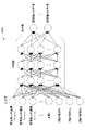
- FIG. 13 is a diagram showing an example of the joint angle estimation model 2322.
- the joint angle estimation model 2322 includes two-dimensional posture data output from the two-dimensional skeleton estimation model 2321 and showing the normalized positions of the joint axes J1 to J6, the camera 40, and the robot 10.
- An example is a multi-layered neural network in which the distance and inclination between the two are used as the input layer and the angles of the joint axes J1 to J6 are used as the output layer.
- the coordinates ( xi , y i ) which are the positions of the centers of the normalized joint axes J1 to J6, and the certainty degree output from the two-dimensional skeleton estimation model 2321 are 0.5 or more. In some cases, it is set to "1", and if it is less than 0.5, it includes a certainty degree c i set to "0" (x i , y i , c i ).
- X-axis tilt Rx is the three-dimensional coordinate values of the camera 40 in the world coordinate system and the robot origin of the robot 10 in the world coordinate system. It is a rotation angle around the X axis, a rotation angle around the Y axis, and a rotation angle around the Z axis between the camera 40 and the robot 10 in the world coordinate system, which is calculated based on the three-dimensional coordinate values of. ..
- the learning unit 305 obtains a two-dimensional skeletal estimation model 2321 and joints.
- Robot 3D skeleton composed of angle estimation model 2322 Robot 3D skeleton composed of 2D skeleton estimation model 2321 and joint angle estimation model 2322 once constructed by further supervised learning on robot 3D skeleton estimation model 232.
- the estimation model 232 may be updated. By doing so, training data can be automatically obtained from the usual shooting of the robot 10, so that the estimation accuracy of the angles of the joint axes J1 to J6 of the robot 10 can be improved on a daily basis.
- the above-mentioned supervised learning may be performed by online learning, batch learning, or mini-batch learning.
- Online learning is a learning method in which supervised learning is performed immediately each time a frame image of the robot 10 is taken and training data is created. Further, in batch learning, while the frame image of the robot 10 is taken and the training data is repeatedly created, a plurality of training data corresponding to the repetition are collected, and all the collected training data are used.
- It is a learning method of supervised learning.
- mini-batch learning is a learning method in which supervised learning is performed each time training data is accumulated to some extent, which is intermediate between online learning and batch learning. With the machine learning device described above, it is possible to generate a robot three-dimensional skeleton estimation model included in the safety vision device 20.
- the safety vision device 20 is not limited to the above-described embodiment, and includes deformation, improvement, and the like within a range in which the object can be achieved.
- the safety vision device 20 calculates one area for the worker U, but is not limited to this.
- the safety vision device 20 may calculate two regions RU1 and RU2 having different sizes for the worker U, similarly to the regions R1 and R2 of the robot 10. It is assumed that the length, depth, and height in the region RU1 are set to be larger than the length, depth, and height in the region RU2.
- the safety vision device 20 for example, the area RU1 of the worker U and the area R1 of the robot 10 overlap, the area RU2 of the worker U and the area R1 of the robot 10 overlap, or the area of the worker U.
- a deceleration instruction to the robot 10 may be output to a robot control device (not shown). Further, when the area RU2 of the smallest worker U and the area R2 of the robot 10 overlap, the safety vision device 20 outputs a stop instruction to the robot 10 to a robot control device (not shown). You may. Although the area of the worker U and the area of the robot 10 are one or two, a plurality of areas of three or more may be set. By doing so, the safety vision device 20 can avoid the collision between the worker U and the robot 10 more finely.
- the safety vision device 20 uses the human 3D skeleton estimation model 231 and the robot 3D skeleton estimation model 232 to input the frame image of the worker U and the robot 10 and the camera 40. From the distance and inclination between the robot 10 and the robot 10, the three-dimensional joint point data of the worker U and the angles of the joint axes J1 to J6 of the robot 10 are estimated, but the present invention is not limited thereto.
- the server 50 stores m human 3D skeleton estimation model 231 and robot 3D skeleton estimation model 232, and is connected to the server 50 via the network 60.
- 20A (1) to 20A (m) may share the human 3D skeleton estimation model 231 and the robot 3D skeleton estimation model 232 (m is an integer of 2 or more). As a result, the human 3D skeleton estimation model 231 and the robot 3D skeleton estimation model 232 can be applied even if a new robot and a safety vision device are arranged.
- Each of the robots 10A (1) to 10A (m) corresponds to the robot 10 in FIG.
- Each of the safety vision devices 20A (1) to 20A (m) corresponds to the safety vision device 20 of FIG.
- each function included in the safety vision device 20 in one embodiment can be realized by hardware, software, or a combination thereof.
- what is realized by software means that it is realized by a computer reading and executing a program.
- Each component included in the safety vision device 20 can be realized by hardware, software including an electronic circuit or the like, or a combination thereof. If realized by software, the programs that make up this software are installed on the computer. In addition, these programs may be recorded on removable media and distributed to users, or may be distributed by being downloaded to a user's computer via a network. In addition, when configured with hardware, some or all of the functions of each component included in the above device are, for example, ASIC (Application Specific Integrated Circuit), gate array, FPGA (Field Programmable Gate Array), CPLD ( It can be configured by an integrated circuit (IC) such as a Complex (Programmable Logical Device).
- ASIC Application Specific Integrated Circuit
- FPGA Field Programmable Gate Array
- CPLD It can be configured by an integrated circuit (IC) such as a Complex (Programmable Logical Device).
- Non-transitory computer-readable media include various types of tangible recording media (Tangible studio media). Examples of non-temporary computer-readable media include magnetic recording media (eg, flexible disks, magnetic tapes, hard disk drives), optomagnetic recording media (eg, optomagnetic disks), CD-ROMs (Read Only Memory), CD-. R, CD-R / W, semiconductor memory (for example, mask ROM, PROM (Programmable ROM), EPROM (Erasable PROM), flash ROM, RAM) are included.
- the program may be supplied to the computer by various types of temporary computer-readable media (Transition computer readable medium).
- temporary computer readable media include electrical, optical, and electromagnetic waves.
- the temporary computer-readable medium can supply the program to the computer via a wired communication path such as an electric wire and an optical fiber, or a wireless communication path.
- the step of describing the program to be recorded on the recording medium is not only the processing performed in chronological order but also the processing executed in parallel or individually even if it is not necessarily processed in chronological order. Also includes.
- the safety vision device and the safety vision system of the present disclosure can take various embodiments having the following configurations.
- the safety vision device 20 of the present disclosure includes a human three-dimensional skeleton estimation model 231 that inputs a two-dimensional image of a human and outputs three-dimensional joint point data indicating the three-dimensional coordinate values of the positions of the human joint points.
- the two-dimensional image of the robot 10 and the distance and inclination between the camera 40 and the robot 10 that captured the two-dimensional image of the robot 10 are input, and the angles of a plurality of joint axes J1 to J6 included in the robot 10 are output.
- the two-dimensional image input by the unit 213 and the input unit 213, and the distance and inclination between the external camera 40 and the robot 10 are input to the human three-dimensional skeleton estimation model 231 and the robot three-dimensional skeleton estimation model 232.
- the estimation unit 214 for estimating the three-dimensional joint point data showing the three-dimensional coordinate values of the positions of the joint points of the worker U and the angles of the plurality of joint axes J1 to J6 included in the robot 10 and the three-dimensional Based on the joint point data and the angles of the plurality of joint axes J1 to J6, the area indicating the range of the worker U and the areas R1 and R2 indicating the range of the robot 10 are calculated, and the calculated area of the worker U and the robot are calculated.
- An approach determination unit 215 that outputs a deceleration or stop instruction to the robot 10 according to the degree of overlap with the area of 10 is provided. According to the safety vision device 20, when an operator intrudes into the operating area of the robot without using the area sensor, the robot can be decelerated or stopped.
- the two-dimensional image may be a frame image taken by the camera 40 at a predetermined frame rate. By doing so, the safety vision device 20 can continuously track the movements of the worker U and the robot 10.
- a notification unit 216 that outputs a warning sound may be further provided. By doing so, the safety vision device 20 can warn the worker U.
- the human 3D skeleton estimation model 231 and the robot 3D skeleton estimation model 232 are accessed from the safety vision device 20 via the network 60. It may be prepared for the server 50 to be connected if possible. By doing so, the safety vision device 20 can apply the trained model even if a new robot and the safety vision device are arranged.
- the safety vision system 1 of the present disclosure includes a robot 10, a camera 40, and a safety vision device 20 according to any one of (1) to (4).
- This secure vision system 1 can produce the same effects as (1) to (4).
- Reliable vision system 10
- Robot 20 Reliable vision device 21
- Control unit 211
- 3D object recognition unit 212
- Self-position estimation unit 213
- Input unit 214
- Estimate unit 215
- Approach judgment unit 216
- Notification unit 22
- Communication unit 23
- Storage unit 231
- Human 3D skeleton estimation model 232
- Robot 3D skeleton estimation model 2321
- Joint angle estimation model 30
- Information acquisition unit 302
- Input data acquisition unit 304
- Label acquisition unit 305
- Learning unit 306
- Camera 60 network
Landscapes
- Engineering & Computer Science (AREA)
- Physics & Mathematics (AREA)
- Computer Vision & Pattern Recognition (AREA)
- General Physics & Mathematics (AREA)
- Theoretical Computer Science (AREA)
- Robotics (AREA)
- Mechanical Engineering (AREA)
- Multimedia (AREA)
- Geometry (AREA)
- Manipulator (AREA)
- Image Analysis (AREA)
Priority Applications (4)
| Application Number | Priority Date | Filing Date | Title |
|---|---|---|---|
| JP2022572201A JP7427115B2 (ja) | 2020-12-21 | 2021-12-14 | 安心ビジョン装置、及び安心ビジョンシステム |
| US18/038,807 US12409572B2 (en) | 2020-12-21 | 2021-12-14 | Safety vision device, and safety vision system |
| CN202180084112.8A CN116745083B (zh) | 2020-12-21 | 2021-12-14 | 安全视觉装置以及安全视觉系统 |
| DE112021005409.0T DE112021005409T5 (de) | 2020-12-21 | 2021-12-14 | Sicherheits-sichtvorrichtung und sicherheits-sichtsystem |
Applications Claiming Priority (2)
| Application Number | Priority Date | Filing Date | Title |
|---|---|---|---|
| JP2020-211721 | 2020-12-21 | ||
| JP2020211721 | 2020-12-21 |
Publications (1)
| Publication Number | Publication Date |
|---|---|
| WO2022138340A1 true WO2022138340A1 (ja) | 2022-06-30 |
Family
ID=82159718
Family Applications (1)
| Application Number | Title | Priority Date | Filing Date |
|---|---|---|---|
| PCT/JP2021/046118 Ceased WO2022138340A1 (ja) | 2020-12-21 | 2021-12-14 | 安心ビジョン装置、及び安心ビジョンシステム |
Country Status (5)
| Country | Link |
|---|---|
| US (1) | US12409572B2 (https=) |
| JP (1) | JP7427115B2 (https=) |
| CN (1) | CN116745083B (https=) |
| DE (1) | DE112021005409T5 (https=) |
| WO (1) | WO2022138340A1 (https=) |
Families Citing this family (2)
| Publication number | Priority date | Publication date | Assignee | Title |
|---|---|---|---|---|
| DE102023117654B4 (de) * | 2023-07-04 | 2025-01-23 | K.A. Schmersal Holding Gmbh & Co. Kg | Verfahren zur Überwachung eines Schutzbereichs basierend auf einem Modellobjektdatensatz mit mindestens einem 3D-Modellobjekt |
| KR102772458B1 (ko) * | 2024-11-19 | 2025-02-26 | 주식회사 엑스와이지 | 사람과 로봇 간의 충돌을 방지하기 위한 실시간 충돌 방지 방법 및 이를 이용한 실시간 충돌 방지 시스템 |
Citations (2)
| Publication number | Priority date | Publication date | Assignee | Title |
|---|---|---|---|---|
| CN104476544A (zh) * | 2014-10-23 | 2015-04-01 | 广东工业大学 | 一种视觉伺服机械臂系统的自适应死区逆模型发生装置 |
| JP2020093373A (ja) * | 2018-12-14 | 2020-06-18 | オムロン株式会社 | ロボット干渉判定装置、ロボット干渉判定方法、ロボット制御装置、およびロボット制御システム |
Family Cites Families (25)
| Publication number | Priority date | Publication date | Assignee | Title |
|---|---|---|---|---|
| JP2004243427A (ja) | 2003-02-12 | 2004-09-02 | Yaskawa Electric Corp | ロボット制御装置およびロボット制御方法 |
| DE102006048166A1 (de) * | 2006-08-02 | 2008-02-07 | Daimler Ag | Verfahren zur Beobachtung einer Person in einem industriellen Umfeld |
| US20150294496A1 (en) * | 2014-04-14 | 2015-10-15 | GM Global Technology Operations LLC | Probabilistic person-tracking using multi-view fusion |
| US9855664B2 (en) * | 2015-11-25 | 2018-01-02 | Denso Wave Incorporated | Robot safety system |
| CN109219856A (zh) * | 2016-03-24 | 2019-01-15 | 宝利根 T·R 有限公司 | 用于人类及机器人协作的系统及方法 |
| US11045955B2 (en) * | 2016-05-26 | 2021-06-29 | Mitsubishi Electric Corporation | Robot control device |
| US10186130B2 (en) * | 2016-07-28 | 2019-01-22 | The Boeing Company | Using human motion sensors to detect movement when in the vicinity of hydraulic robots |
| US11518051B2 (en) * | 2017-02-07 | 2022-12-06 | Veo Robotics, Inc. | Dynamic, interactive signaling of safety-related conditions in a monitored environment |
| US11541543B2 (en) * | 2017-02-07 | 2023-01-03 | Veo Robotics, Inc. | Dynamic, interactive signaling of safety-related conditions in a monitored environment |
| DE102017010718A1 (de) * | 2017-11-17 | 2019-05-23 | Kuka Deutschland Gmbh | Verfahren und Mittel zum Betreiben einer Roboteranordnung |
| US20210073096A1 (en) | 2017-11-17 | 2021-03-11 | Mitsubishi Electric Corporation | Three-dimensional space monitoring device and three-dimensional space monitoring method |
| JP7058126B2 (ja) * | 2018-01-12 | 2022-04-21 | 株式会社日立製作所 | ロボット制御装置および自動組立システム |
| US10929654B2 (en) * | 2018-03-12 | 2021-02-23 | Nvidia Corporation | Three-dimensional (3D) pose estimation from a monocular camera |
| CN108527370B (zh) | 2018-04-16 | 2020-06-02 | 北京卫星环境工程研究所 | 基于视觉的人机共融安全防护控制系统 |
| JP7379373B2 (ja) * | 2018-04-27 | 2023-11-14 | アルコン インコーポレイティド | 立体視覚化カメラ及び統合ロボットプラットフォーム |
| KR20200036088A (ko) * | 2018-09-20 | 2020-04-07 | 한국전자통신연구원 | 상호 작용 행위 생성 장치 및 방법 |
| JP7505791B2 (ja) * | 2019-02-27 | 2024-06-25 | ヴェオ ロボティクス, インコーポレイテッド | 安全定格マルチセル作業空間マッピングおよび監視 |
| JP7036078B2 (ja) * | 2019-03-28 | 2022-03-15 | オムロン株式会社 | 制御システム、制御方法、および制御ユニット |
| US11364629B2 (en) * | 2019-04-27 | 2022-06-21 | The Johns Hopkins University | Data-driven position estimation and collision detection for flexible manipulator |
| CN110480634B (zh) * | 2019-08-08 | 2020-10-02 | 北京科技大学 | 一种针对机械臂运动控制的手臂引导运动控制方法 |
| GB2586604B (en) * | 2019-08-28 | 2022-10-05 | Canon Kk | 3d representation reconstruction from images using volumic probability data |
| KR102916297B1 (ko) * | 2019-11-15 | 2026-01-21 | 엘지전자 주식회사 | 동적 장애물을 식별하는 방법 및 이를 구현한 로봇 |
| JP7409499B2 (ja) * | 2020-06-10 | 2024-01-09 | 日本電気株式会社 | 画像処理装置、画像処理方法、及びプログラム |
| JP7478848B2 (ja) * | 2020-12-21 | 2024-05-07 | ファナック株式会社 | 教師データ生成装置、機械学習装置、及びロボット関節角度推定装置 |
| JP7468871B2 (ja) * | 2021-03-08 | 2024-04-16 | 国立大学法人 東京大学 | 3d位置取得方法及び装置 |
-
2021
- 2021-12-14 DE DE112021005409.0T patent/DE112021005409T5/de active Pending
- 2021-12-14 WO PCT/JP2021/046118 patent/WO2022138340A1/ja not_active Ceased
- 2021-12-14 US US18/038,807 patent/US12409572B2/en active Active
- 2021-12-14 JP JP2022572201A patent/JP7427115B2/ja active Active
- 2021-12-14 CN CN202180084112.8A patent/CN116745083B/zh active Active
Patent Citations (2)
| Publication number | Priority date | Publication date | Assignee | Title |
|---|---|---|---|---|
| CN104476544A (zh) * | 2014-10-23 | 2015-04-01 | 广东工业大学 | 一种视觉伺服机械臂系统的自适应死区逆模型发生装置 |
| JP2020093373A (ja) * | 2018-12-14 | 2020-06-18 | オムロン株式会社 | ロボット干渉判定装置、ロボット干渉判定方法、ロボット制御装置、およびロボット制御システム |
Also Published As
| Publication number | Publication date |
|---|---|
| CN116745083A (zh) | 2023-09-12 |
| DE112021005409T5 (de) | 2023-08-03 |
| US20230415363A1 (en) | 2023-12-28 |
| JPWO2022138340A1 (https=) | 2022-06-30 |
| JP7427115B2 (ja) | 2024-02-02 |
| CN116745083B (zh) | 2025-12-16 |
| US12409572B2 (en) | 2025-09-09 |
Similar Documents
| Publication | Publication Date | Title |
|---|---|---|
| JP4167954B2 (ja) | ロボット及びロボット移動方法 | |
| US10818099B2 (en) | Image processing method, display device, and inspection system | |
| JP6589604B2 (ja) | ティーチング結果表示システム | |
| JP2017094466A (ja) | ロボットモニタシステム | |
| CN115514885B (zh) | 基于单双目融合的远程增强现实随动感知系统及方法 | |
| CN104385282A (zh) | 一种视觉智能数控系统及其视觉计测方法 | |
| JP7427115B2 (ja) | 安心ビジョン装置、及び安心ビジョンシステム | |
| JP7517803B2 (ja) | ロボット教示システム、画像生成方法、及びプログラム | |
| CN111230888A (zh) | 一种基于rgbd相机的上肢外骨骼机器人避障方法 | |
| CN111445519A (zh) | 一种工业机器人三维姿态估计方法、装置及存储介质 | |
| CN116833999A (zh) | 一种机器人远程控制系统和方法 | |
| CN114299039A (zh) | 一种机器人及其碰撞检测装置和方法 | |
| JP2022153717A (ja) | 技術伝承トレースシステム及び技術伝承トレース方法 | |
| CN118927245A (zh) | 一种基于vr头显的机器人遥操作系统、方法和设备 | |
| JP7478848B2 (ja) | 教師データ生成装置、機械学習装置、及びロボット関節角度推定装置 | |
| RU2685996C1 (ru) | Способ и система предиктивного избегания столкновения манипулятора с человеком | |
| JP7575487B2 (ja) | 拡張現実表示装置、及び拡張現実表示システム | |
| WO2021217444A1 (zh) | 深度图生成方法、电子设备、计算处理设备及存储介质 | |
| JPH0386484A (ja) | ロボットの遠隔操作装置 | |
| JP2024023104A (ja) | ロボット制御システム、装置、方法及びプログラム | |
| Ganatra et al. | Enhancing Human-Robot Teleoperation through Depth Sensing and eXtended Reality | |
| CN111390885B (zh) | 一种示教视觉调整方法、装置、系统和摄像装置 | |
| Sukumar et al. | Augmented reality-based tele-robotic system architecture for on-site construction | |
| KR102245760B1 (ko) | 테이블 탑 디바이스 및 이를 포함하는 테이블 탑 시스템 | |
| CN118204973A (zh) | 一种人机协作过程中多元融合的碰撞检测方法 |
Legal Events
| Date | Code | Title | Description |
|---|---|---|---|
| 121 | Ep: the epo has been informed by wipo that ep was designated in this application |
Ref document number: 21910489 Country of ref document: EP Kind code of ref document: A1 |
|
| ENP | Entry into the national phase |
Ref document number: 2022572201 Country of ref document: JP Kind code of ref document: A |
|
| WWE | Wipo information: entry into national phase |
Ref document number: 18038807 Country of ref document: US |
|
| WWE | Wipo information: entry into national phase |
Ref document number: 202180084112.8 Country of ref document: CN |
|
| 122 | Ep: pct application non-entry in european phase |
Ref document number: 21910489 Country of ref document: EP Kind code of ref document: A1 |
|
| WWG | Wipo information: grant in national office |
Ref document number: 18038807 Country of ref document: US |