WO2022138313A1 - Circuit construction object - Google Patents
Circuit construction object Download PDFInfo
- Publication number
- WO2022138313A1 WO2022138313A1 PCT/JP2021/045972 JP2021045972W WO2022138313A1 WO 2022138313 A1 WO2022138313 A1 WO 2022138313A1 JP 2021045972 W JP2021045972 W JP 2021045972W WO 2022138313 A1 WO2022138313 A1 WO 2022138313A1
- Authority
- WO
- WIPO (PCT)
- Prior art keywords
- heat
- case
- metal plate
- generating component
- lower case
- Prior art date
Links
- 238000010276 construction Methods 0.000 title abstract 3
- 229910052751 metal Inorganic materials 0.000 claims abstract description 106
- 239000002184 metal Substances 0.000 claims abstract description 106
- 230000017525 heat dissipation Effects 0.000 claims abstract description 91
- 238000003780 insertion Methods 0.000 claims description 102
- 230000037431 insertion Effects 0.000 claims description 102
- 230000002093 peripheral effect Effects 0.000 claims description 26
- 238000010521 absorption reaction Methods 0.000 claims description 24
- 238000009413 insulation Methods 0.000 abstract description 10
- 230000020169 heat generation Effects 0.000 abstract description 5
- 239000010408 film Substances 0.000 description 126
- 239000000945 filler Substances 0.000 description 56
- 238000000034 method Methods 0.000 description 16
- 230000000149 penetrating effect Effects 0.000 description 12
- 230000005855 radiation Effects 0.000 description 9
- 210000000078 claw Anatomy 0.000 description 8
- 239000000463 material Substances 0.000 description 8
- XLYOFNOQVPJJNP-UHFFFAOYSA-N water Substances O XLYOFNOQVPJJNP-UHFFFAOYSA-N 0.000 description 8
- 238000009833 condensation Methods 0.000 description 6
- 230000005494 condensation Effects 0.000 description 6
- 230000000694 effects Effects 0.000 description 6
- 229920005989 resin Polymers 0.000 description 6
- 239000011347 resin Substances 0.000 description 6
- 239000000853 adhesive Substances 0.000 description 5
- 230000001070 adhesive effect Effects 0.000 description 5
- -1 polyethylene terephthalate Polymers 0.000 description 5
- 238000007789 sealing Methods 0.000 description 5
- 239000004642 Polyimide Substances 0.000 description 4
- 229920000139 polyethylene terephthalate Polymers 0.000 description 4
- 239000005020 polyethylene terephthalate Substances 0.000 description 4
- 229920001721 polyimide Polymers 0.000 description 4
- 239000004810 polytetrafluoroethylene Substances 0.000 description 4
- 229920001343 polytetrafluoroethylene Polymers 0.000 description 4
- 229920003002 synthetic resin Polymers 0.000 description 4
- 239000000057 synthetic resin Substances 0.000 description 4
- 239000011231 conductive filler Substances 0.000 description 3
- 230000006866 deterioration Effects 0.000 description 3
- 239000004519 grease Substances 0.000 description 3
- 239000011112 polyethylene naphthalate Substances 0.000 description 3
- 238000003466 welding Methods 0.000 description 3
- 229910052582 BN Inorganic materials 0.000 description 2
- PZNSFCLAULLKQX-UHFFFAOYSA-N Boron nitride Chemical compound N#B PZNSFCLAULLKQX-UHFFFAOYSA-N 0.000 description 2
- 229910052581 Si3N4 Inorganic materials 0.000 description 2
- 230000002411 adverse Effects 0.000 description 2
- PNEYBMLMFCGWSK-UHFFFAOYSA-N aluminium oxide Inorganic materials [O-2].[O-2].[O-2].[Al+3].[Al+3] PNEYBMLMFCGWSK-UHFFFAOYSA-N 0.000 description 2
- 238000005452 bending Methods 0.000 description 2
- 239000002131 composite material Substances 0.000 description 2
- PMHQVHHXPFUNSP-UHFFFAOYSA-M copper(1+);methylsulfanylmethane;bromide Chemical compound Br[Cu].CSC PMHQVHHXPFUNSP-UHFFFAOYSA-M 0.000 description 2
- 230000007547 defect Effects 0.000 description 2
- 238000010586 diagram Methods 0.000 description 2
- 229920001971 elastomer Polymers 0.000 description 2
- 239000003822 epoxy resin Substances 0.000 description 2
- TWNQGVIAIRXVLR-UHFFFAOYSA-N oxo(oxoalumanyloxy)alumane Chemical compound O=[Al]O[Al]=O TWNQGVIAIRXVLR-UHFFFAOYSA-N 0.000 description 2
- 238000005192 partition Methods 0.000 description 2
- 229920003207 poly(ethylene-2,6-naphthalate) Polymers 0.000 description 2
- 229920000515 polycarbonate Polymers 0.000 description 2
- 239000004417 polycarbonate Substances 0.000 description 2
- 229920000647 polyepoxide Polymers 0.000 description 2
- HQVNEWCFYHHQES-UHFFFAOYSA-N silicon nitride Chemical compound N12[Si]34N5[Si]62N3[Si]51N64 HQVNEWCFYHHQES-UHFFFAOYSA-N 0.000 description 2
- 229920002050 silicone resin Polymers 0.000 description 2
- 229910000838 Al alloy Inorganic materials 0.000 description 1
- RYGMFSIKBFXOCR-UHFFFAOYSA-N Copper Chemical compound [Cu] RYGMFSIKBFXOCR-UHFFFAOYSA-N 0.000 description 1
- 229910000881 Cu alloy Inorganic materials 0.000 description 1
- 230000004308 accommodation Effects 0.000 description 1
- 229910052782 aluminium Inorganic materials 0.000 description 1
- XAGFODPZIPBFFR-UHFFFAOYSA-N aluminium Chemical compound [Al] XAGFODPZIPBFFR-UHFFFAOYSA-N 0.000 description 1
- 229910052802 copper Inorganic materials 0.000 description 1
- 239000010949 copper Substances 0.000 description 1
- 238000006073 displacement reaction Methods 0.000 description 1
- 239000013013 elastic material Substances 0.000 description 1
- 239000000806 elastomer Substances 0.000 description 1
- 238000010292 electrical insulation Methods 0.000 description 1
- 238000012986 modification Methods 0.000 description 1
- 230000004048 modification Effects 0.000 description 1
- 238000000465 moulding Methods 0.000 description 1
- 229920003223 poly(pyromellitimide-1,4-diphenyl ether) Polymers 0.000 description 1
- 238000003825 pressing Methods 0.000 description 1
- 238000000638 solvent extraction Methods 0.000 description 1
- 239000010409 thin film Substances 0.000 description 1
Images


Classifications
-
- H—ELECTRICITY
- H05—ELECTRIC TECHNIQUES NOT OTHERWISE PROVIDED FOR
- H05K—PRINTED CIRCUITS; CASINGS OR CONSTRUCTIONAL DETAILS OF ELECTRIC APPARATUS; MANUFACTURE OF ASSEMBLAGES OF ELECTRICAL COMPONENTS
- H05K7/00—Constructional details common to different types of electric apparatus
- H05K7/20—Modifications to facilitate cooling, ventilating, or heating
- H05K7/2039—Modifications to facilitate cooling, ventilating, or heating characterised by the heat transfer by conduction from the heat generating element to a dissipating body
- H05K7/20436—Inner thermal coupling elements in heat dissipating housings, e.g. protrusions or depressions integrally formed in the housing
- H05K7/20445—Inner thermal coupling elements in heat dissipating housings, e.g. protrusions or depressions integrally formed in the housing the coupling element being an additional piece, e.g. thermal standoff
- H05K7/20463—Filling compound, e.g. potted resin
-
- B—PERFORMING OPERATIONS; TRANSPORTING
- B60—VEHICLES IN GENERAL
- B60R—VEHICLES, VEHICLE FITTINGS, OR VEHICLE PARTS, NOT OTHERWISE PROVIDED FOR
- B60R16/00—Electric or fluid circuits specially adapted for vehicles and not otherwise provided for; Arrangement of elements of electric or fluid circuits specially adapted for vehicles and not otherwise provided for
- B60R16/02—Electric or fluid circuits specially adapted for vehicles and not otherwise provided for; Arrangement of elements of electric or fluid circuits specially adapted for vehicles and not otherwise provided for electric constitutive elements
-
- H—ELECTRICITY
- H02—GENERATION; CONVERSION OR DISTRIBUTION OF ELECTRIC POWER
- H02G—INSTALLATION OF ELECTRIC CABLES OR LINES, OR OF COMBINED OPTICAL AND ELECTRIC CABLES OR LINES
- H02G3/00—Installations of electric cables or lines or protective tubing therefor in or on buildings, equivalent structures or vehicles
- H02G3/02—Details
- H02G3/08—Distribution boxes; Connection or junction boxes
- H02G3/16—Distribution boxes; Connection or junction boxes structurally associated with support for line-connecting terminals within the box
Definitions
- This disclosure relates to a circuit configuration having heat generating parts.
- a heat dissipation structure for dissipating heat from the heat-generating components may be provided.
- a heat radiating portion of a bus bar connected to a connection portion of a relay housed in a case is exposed to the outside through an opening provided in the case, and the heat radiating portion is provided with insulating heat conduction.
- a configuration is disclosed in which the battery is brought into contact with a metal housing via a seat. As a result, the heat generated by the relay can be thermally conducted to the housing and dissipated.
- dew condensation may occur around the case of the circuit configuration fixed to the housing due to the temperature difference between the circuit configuration and the housing. It has been found that the water accumulated due to dew condensation may enter the case through the opening of the case, so that the insulation between the housing and the heat dissipation part of the bus bar may not be ensured.
- the circuit configuration of the present disclosure includes a heat-generating component that generates heat when energized, a metal plate that is connected to a connection portion of the heat-generating component and has a heat-dissipating portion that is in thermal contact with an external heat-dissipating object, and the heat-generating component and the metal. It includes a case having an opening for accommodating the plate and exposing the heat radiating portion of the metal plate to the outside, and an insulating film for sealing the opening of the case and being fixed to the case.
- circuit configuration of the present disclosure it is possible to advantageously secure the waterproofness of the case and the insulation between the heat radiating portion and the heat radiating target.
- FIG. 1 is a perspective view of a circuit configuration according to the first embodiment.
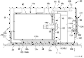
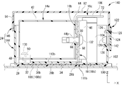
- FIG. 2 is a plan view of the circuit configuration shown in FIG. 1 and is a diagram showing a state in which the upper case is removed.
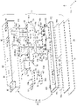
- FIG. 3 is an exploded perspective view of the circuit configuration shown in FIG.
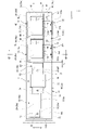
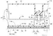
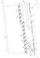
- FIG. 4 is a sectional view taken along line IV-IV in FIG.
- FIG. 5 is a sectional view taken along line VV in FIG.
- FIG. 6 is a perspective view from the plane side of the lower case constituting the circuit configuration shown in FIG. 1.
- FIG. 7 is a perspective view from the bottom surface side of the lower case shown in FIG.
- FIG. 8 is an enlarged view showing the bottom surface of the lower case shown in FIG. 7, and is a cross-sectional perspective view of a portion corresponding to the VIII-VIII cross section in FIG.
- FIG. 9 is a vertical sectional view of a circuit configuration according to another aspect, and is a diagram corresponding to FIG. 4.
- the circuit configuration of the present disclosure is (1) Accommodating a heat-generating component that generates heat by energization, a metal plate having a heat-dissipating portion that is connected to the connection portion of the heat-generating component and has a heat-dissipating portion that makes thermal contact with an external heat-dissipating object, and the heat-generating component and the metal plate. It includes a case having an opening that exposes the heat radiating portion of the metal plate to the outside, and an insulating film that seals the opening of the case and is fixed to the case.
- the opening provided in the case for exposing the heat radiating portion of the metal plate to the outside is sealed by an insulating film. Therefore, even if dew condensation occurs around the case of the circuit structure due to the temperature difference between the external heat radiation target (for example, a metal housing or the like) and the circuit structure that the heat radiating part is in thermal contact with. , Water accumulated due to dew condensation can be prevented from entering the case through the opening of the case. As a result, the waterproofness of the case having an opening is improved, the short circuit between the heat radiating part and the heat radiating target is prevented due to the water entering the case, and the insulation between the heat radiating part and the heat radiating target is advantageous. Can be secured.
- the use of the metal plate is not limited as long as it is provided with a heat radiating portion.
- the metal plate for energization may be provided with the radiating portion, or the metal plate for energization may be provided separately.
- a heat radiating portion may be provided on the metal plate of the above.
- "exposing the heat radiating portion of the metal plate to the outside” means making the heat radiating portion thermally contactable with the heat radiating object outside the case without passing through the case.
- the insulating film is not particularly limited as long as it has insulating properties and can be fixed to the case by sealing the opening of the case.
- PET polyethylene terephthalate
- PET polyethylene naphthalate
- a film-like material made of (PEN), polytetrafluoroethylene (PTFE), polycarbonate (PC), polyimide (PI) or the like can be advantageously adopted.
- the film thickness of the insulating film is not particularly limited, but a relatively thin film thickness is preferable, for example, 500 ⁇ m or less, more preferably 500 ⁇ m or less, in order to advantageously achieve thermal conductivity from the heat radiating portion to the heat radiating target. Those having a thickness of 250 ⁇ m or less can be preferably adopted.
- a well-known method such as adhesion or welding can be adopted.
- the case includes an upper case and a lower case, the heat generating component is fixed to at least one of the upper case and the lower case, the lower case has a mounting surface on the heat dissipation target, and the above-mentioned mounting surface is described.
- the lower case has a positioning portion for positioning the heat radiating portion of the metal plate arranged in the opening so as to be flush with the above-mentioned mounting surface.
- the metal plate is provided with a connection portion of the heat generating component to the connection portion, and when the heat dissipation portion is positioned by the positioning portion, the tolerance of the connection position between the connection portion and the connection portion is set. It is preferable to have a tolerance absorption structure for absorption.
- the lower case that can be assembled to the upper case has a mounting surface on the heat dissipation target. An opening is provided on the mounting surface to expose the heat radiating portion of the metal plate. Since the lower case has a positioning portion for positioning the heat radiating portion so as to be flush with the mounting surface, a step is generated between the radiating portion and the mounting surface, which adversely affects the adhesion of the insulating film. The occurrence of defects is suppressed or prevented. In addition, it is necessary to connect the connection part of the metal plate where the heat dissipation part is positioned on the lower case side to the connection part of the heat generating component, but the circuit configuration absorbs the tolerance of the connection position between the connection part and the connection part.
- connection portion of the metal plate whose heat radiating portion is positioned on the lower case can be connected to the connection portion of the heat generating component without any problem.
- the heat-generating component may be fixed to either the upper case or the lower case, but the one in which the heat-generating component is fixed to the upper case is the connection between the connection portion of the heat-generating component and the metal plate when the upper case and the lower case are assembled. Since the deviation due to the tolerance of each member tends to be large at the connection position with the portion, the tolerance absorption effect can be enjoyed more effectively.
- the shape of the positioning part can be arbitrarily set as long as the lower surface of the heat dissipation part can be positioned so as to be flush with the mounting surface of the lower case.
- the lower surface of the heat radiating portion and the mounting surface are flush with each other by contacting a part or all of the upper surface of the heat radiating portion can be preferably adopted.
- the heat-generating component includes a first heat-generating component
- the metal plate includes a metal plate for a first heat-generating component connected to the connection portion of the first heat-generating component.
- the connection portion of the first heat-generating component and the connection portion of the metal plate for the first heat-generating component are fastened using a first bolt extending in a direction orthogonal to the assembling direction of the upper case and the lower case.
- a long hole-shaped bolt insertion hole extending in the assembling direction of the upper case and the lower case is provided at the fastening portion of the metal plate for the first heat generating component, and the first is provided by the bolt insertion hole.
- the tolerance absorption structure is configured and the tolerance absorption structure includes the first tolerance absorption structure.
- connection portion of the first heat-generating component and the connection portion of the metal plate for the first heat-generating component are fastened by a first bolt extending in a direction orthogonal to the assembling direction of the upper case and the lower case, and the metal for the first heat-generating component is fastened.
- the first tolerance absorption structure can be provided with a simple structure in which the bolt insertion hole provided in the plate is an elongated hole extending in the assembly direction.
- the upper case has a top wall and a side wall projecting from the top wall toward the lower case, and the lower case faces the bottom wall and the bottom wall toward the upper case. It is preferable that the side wall and at least one of the peripheral walls are provided with work holes through which the first bolt and the tool for fastening the first bolt can be inserted.
- connection part of the metal plate for the first heat generating part where the heat dissipation part is positioned is positioned with respect to the positioning part of the lower case from the outside of the upper case to the connection part of the first heat generating part. This is because it is possible to realize the positioning of the heat radiating portion and the lower case and the tolerance absorption of the connection position between the connecting portion and the connecting portion with good workability.
- the metal plate for the first heat generating component is bent in an L shape, and one end of the metal plate for the first heat generating component is placed in front of the lower case.
- the heat radiation portion that extends parallel to the surface, the other end of the metal plate for the first heat generating component is the connection portion that rises toward the upper case, and the connection portion is on the previously described mounting surface of the lower case.
- a slit-shaped insertion hole that allows the insertion of the metal and a recess that is connected to the insertion hole and is recessed toward the upper case to accommodate the heat dissipation portion, and includes the insertion hole and the recess.
- An opening is formed, and a positioning portion for a first metal plate for positioning the metal plate for the first heat generating component is configured by a top plate of the recess, and the positioning portion is a positioning portion for the first metal plate. Is preferably contained.
- connection part of the metal plate for the first heat-generating component can be inserted into the case while reducing the opening area of the insertion hole provided on the mounting surface of the lower case. Can be done.
- the heat radiating portion can be accommodated in the concave portion so that the radiating portion and the mounting surface are flush with each other.
- the positioning portion for the first metal plate can be configured so that the heat radiating portion and the mounting surface are flush with each other by the top plate of the recess, the radiating portion can be stably held by the lower case, and further, the radiating portion and the heat radiating portion can be held. Insulation between the circuit in the case and the circuit can also be advantageously secured.
- the heat generating component includes the second heat generating component, and the metal plate is connected to the connection portion of the second heat generating component.
- the metal plate for parts is included, and the metal plate for second heat generating parts is provided on one end side and extends in parallel with the previously described mounting surface of the lower case, and the heat radiation portion is provided on the other end side. It has a connection portion that is located closer to the upper case side than the portion and extends in parallel with the heat dissipation portion, and a connecting portion that rises from the heat dissipation portion toward the connection portion, and is provided on the previously described mounting surface of the lower case.
- Is provided with an insertion hole that allows the connection portion and the connection portion to be inserted, and a recess that is connected to the insertion hole and is recessed toward the upper case side to accommodate the heat radiation portion.
- the opening is configured to include a recess, and the top plate of the recess constitutes a positioning portion for a second metal plate for positioning the metal plate for the second heat generating component, and the positioning portion is the first.
- a positioning portion for a metal plate is included, and the connection portion is fastened to the connection portion of the second heat generating component by a second bolt, and the second bolt housed in the upper case is The nut to be fastened is held displaceably in a direction away from the previously described mounting surface of the lower case, thereby forming a second tolerance absorption structure, wherein the tolerance absorption structure comprises the second tolerance absorption structure. It is preferable to include it.
- the lower case that can be assembled to the upper case has a mounting surface on the heat dissipation target. Further, an opening is provided on the mounting surface to expose the heat radiating portion of the metal plate for the second heat generating component. Since the lower case has a positioning portion for the second metal plate that positions the heat radiating portion so as to be flush with the mounting surface, a step is generated between the radiating portion and the mounting surface, and the insulating film is provided. The occurrence of defects that adversely affect sticking is suppressed or prevented. In addition, it is necessary to connect the connection portion of the metal plate for the second heat generating component whose heat dissipation portion is positioned on the lower case side to the connection portion of the second heat generating component.
- the insertion hole includes a first region where the insertion of the connection portion is allowed and a second region where the connection portion is allowed to be inserted, and the insertion hole in the insertion hole. It is preferable that the lid portion covering the first region is detachably fixed to the above-mentioned mounting surface.
- the wide open insertion hole where the connection part of the metal plate for the second heat-generating component to be the live part is exposed is closed. It can be covered by the part. This makes it possible to advantageously achieve measures to prevent electric shock and further improve the waterproofness inside the case.
- the case is provided with a plurality of protrusions arranged around the peripheral edge of the insulating film with a gap.
- the facing gap between the peripheral edge portion and the protruding portion of the insulating film and / or the facing gap between the protruding portions is set to a size that prevents the intrusion of fingers.
- the case includes an upper case and a lower case, and the plurality of protrusions are triangular in the projection of the upper case and the lower case in the assembling direction, respectively, and are located inside. It is preferable that the width is gradually narrowed toward the insulating film.
- the gap between the protrusions gradually increases toward the inside. As a result, it is easy to capture the air between the insulating film and the filling member, and the air can be discharged more efficiently. In addition, since the gap between the protrusions is the smallest on the outside, the effect of preventing the intrusion of fingers is more effectively exhibited.
- the heat radiating portion is in contact with the heat radiating target via the heat conductive filling member arranged on the insulating film side.
- the heat conductive filling member for example, a composite material in which a heat conductive filler is filled in a resin such as an epoxy resin or a silicone resin is adopted.
- alumina aluminum oxide
- boron nitride aluminum nitride
- silicon nitride and the like are used.
- the heat-conducting filling member may be in various forms such as a sheet, a gel, and a grease.
- the circuit configuration 10 of the first embodiment of the present disclosure is mounted on a vehicle (not shown) such as an electric vehicle or a hybrid vehicle, and power is supplied from a power source such as a battery (not shown) to a load (not shown) such as a motor. Supply and control.
- the circuit configuration 10 can be arranged in any direction, but in the following, the X direction in the figure will be described as forward, the Y direction as left, and the Z direction as upward. Further, for a plurality of the same members, a reference numeral may be added to only a part of the members, and the reference numeral may be omitted for other members.
- the circuit configuration 10 includes a fuse 12 as a second heat generating component and a relay 14 as a first heat generating component as heat generating components that generate heat when energized. Further, the circuit configuration 10 serves as a metal plate connected to the energizing bus bar 16 connected to the connection portions 38 and 44 of the fuse 12 and the relay 14 described later and the connection portions 38 and 44 of the fuse 12 and the relay 14. The bus bar 18 for heat dissipation is provided.
- the circuit configuration 10 includes a case 24 including an upper case 20 and a lower case 22, and the fuse 12, the relay 14, the energizing bus bar 16, and the heat radiating bus bar 18 are housed in the case 24.
- the heat-dissipating bus bar 18 includes a heat-dissipating portion 26, and the heat-dissipating portion 26 is exposed to the outside of the case 24 through an opening 28 provided in the case 24, such as a battery pack housing that is an external heat-dissipating target. Is in thermal contact with the metal housing 29 of the above. That is, the fact that the heat radiating portion 26 is exposed to the outside by the opening 28 of the case 24 means that the heat radiating portion 26 can be thermally contacted with the heat radiating target outside the case 24 without passing through the case 24.
- the circuit configuration 10 includes an insulating film 30 that seals the opening 28 and a filler 32 as a heat-conducting filling member.
- the insulating film 30 covers the contact surface 34 of the heat radiating portion 26 with respect to the housing 29 and is fixed to the case 24.
- the filler 32 is in thermal contact with the heat radiating portion 26 via the insulating film 30, and is arranged between the insulating film 30 and the housing 29. Then, the heat radiating portion 26 is in thermal contact with the housing 29 via the insulating film 30 and the filler 32.
- the housing 29 is shown by a two-dot chain line.
- two relays 14 are provided side by side in the left-right direction, the left relay 14 is the first relay 14a, and the right relay 14 is the second relay 14b.
- the fuse 12 is arranged on the left side of the first relay 14a on the left side.
- four energizing bus bars 16 are provided, and the first to fourth energizing bus bars 16a to 16d are provided in order from the left.
- five heat radiating bus bars 18 are provided, and the first to fifth heat radiating bus bars 18a to 18e are provided in order from the left.
- two insulating films 30 are provided side by side in the left-right direction, the left insulating film 30 is the first insulating film 30a, and the right insulating film 30 is the second insulating film 30b.
- the fuse 12 includes a fuse body 36 having a substantially rectangular parallelepiped shape.
- the fuse main body 36 is provided with metal connecting portions 38, 38 protruding from both sides in the left-right direction.
- Bolt insertion holes 40, 40 penetrating in the vertical direction are formed in these connection portions 38, 38.
- the bolt insertion hole 40 on the right side has an elongated hole shape in which the dimension in the left-right direction is larger than the dimension in the front-rear direction.
- the first and second relays 14a and 14b are provided with relay bodies 42 and 42 having a rectangular parallelepiped shape, respectively.
- a pair of connecting portions 44, 44 are provided on the front surface of each relay main body 42 so as to be separated from each other in the left-right direction. That is, the first relay 14a and the second relay 14b are provided with a total of four connection portions 44, which are the first to fourth connection portions 44a to 44d in order from the left.
- the first relay 14a is provided with the first and second connection portions 44a and 44b.
- the second relay 14b is provided with third and fourth connection portions 44c and 44d.
- a partition plate for partitioning between the first connection portion 44a and the second connection portion 44b in the first relay 14a and between the third connection portion 44c and the fourth connection portion 44d in the second relay 14b. 46 is provided so as to project forward.
- each relay main body 42 is provided with mounting portions 48 projecting outward on both sides in the left-right direction.
- Bolt insertion holes 50 that penetrate in the vertical direction are formed in these mounting portions 48.
- the first to fourth energization bus bars 16a to 16d are formed by bending a metal plate material into a predetermined shape by press working or the like.
- the material of each of the energizing bus bars 16a to 16d is not limited, but copper, a copper alloy, aluminum, an aluminum alloy, or the like is preferably adopted.
- the first energizing bus bar 16a is a member connected to the connection portion 38 on the left side of the fuse 12, and extends in the left-right direction as a whole.
- the left end portion of the first energizing bus bar 16a is the external connection portion 52, and the right end portion is the fuse connection portion 54.
- the second energizing bus bar 16b is a member that connects the right side connection portion 38 of the fuse 12 and the first connection portion 44a of the first relay 14a, and extends in the left-right direction as a whole.
- the left end of the second energizing bus bar 16b is a fuse connecting portion 60, and a bolt insertion hole 62 penetrating in the vertical direction, which is the plate thickness direction, is formed.
- the right end portion of the second energizing bus bar 16b is a relay connecting portion 64, and a bolt insertion hole 66 penetrating in the front-rear direction, which is the plate thickness direction, is formed.
- the third energizing bus bar 16c is a member that connects the second connection portion 44b of the first relay 14a and the third connection portion 44c of the second relay 14b, and extends in the left-right direction as a whole.
- the left and right ends of the third energizing bus bar 16c are relay connecting portions 68, 68, and bolt insertion holes 70, 70 penetrating in the front-rear direction, which is the plate thickness direction, are formed.
- a rectangular external connection portion 72 projecting forward is provided at the upper end portion of the third energization bus bar 16c in the central portion in the left-right direction, and a bolt insertion hole 74 penetrating in the vertical direction in the plate thickness direction is provided. It is formed.
- the fourth energizing bus bar 16d is a member connected to the fourth connection portion 44d of the second relay 14b, and extends in the left-right direction as a whole.
- the left end of the fourth energizing bus bar 16d is a relay connecting portion 76, and a bolt insertion hole 78 penetrating in the front-rear direction, which is the plate thickness direction, is formed.
- a rectangular external connecting portion 80 projecting forward is provided at the right end portion of the fourth energizing bus bar 16d, and a bolt insertion hole 82 penetrating in the vertical direction, which is the plate thickness direction, is formed.
- the first to fifth heat dissipation bus bars 18a to 18e are formed by bending a metal plate material into a predetermined shape by press working or the like.
- the material of the heat radiating bus bars 18a to 18e is not limited, but the same material as the energizing bus bars 16 (first to fourth energizing bus bars 16a to 16d) can be adopted.
- the first heat dissipation bus bar 18a is a member connected to the left connection portion 38 of the fuse 12 (second heat generating component), and extends in the left-right direction as a whole. That is, of the metal plates (first to fifth heat radiating bus bars 18a to 18e), the first heat radiating bus bar 18a is the second heat generating component metal plate connected to the second heat generating component (fuse 12).
- the left end portion on one end side of the first heat radiation bus bar 18a is a heat radiation unit 26 (first heat radiation unit 26a), and extends in the horizontal direction (XY plane) with predetermined left-right dimensions.
- the right end portion on the other end side of the first heat dissipation bus bar 18a is a fuse connection portion 84 which is a connection portion to the connection portion 38, and is located above the first heat dissipation portion 26a (upper case 20 side). Then, it spreads in the horizontal direction parallel to the first heat radiating portion 26a.
- the fuse connection portion 84 is formed with a bolt insertion hole 86 that penetrates in the vertical direction, which is the plate thickness direction.
- the first heat radiating portion 26a and the fuse connecting portion 84 are connected by a connecting portion 87 extending in the vertical direction, and the connecting portion 87 rises from the right end of the first heat radiating portion 26a toward the left end of the fuse connecting portion 84. There is.
- the second to fifth heat dissipation bus bars 18b to 18e are members connected to the first to fourth connection portions 44a to 44d of the first and second relays 14a and 14b (first heat generating parts). That is, of the metal plates (first to fifth heat dissipation bus bars 18a to 18e), the second to fifth heat dissipation bus bars 18b to 18e are connected to the first heat generating component (first and second relays 14a and 14b). It is a metal plate for the first heat generating part.
- the second to fifth heat radiating bus bars 18b to 18e are bent in an L shape as a whole, and the heat radiating portions 26 (second to fifth heat radiating portions 26b to each) spread in the horizontal direction (XY plane) at one end thereof.
- each relay connection portion 88 is a connection portion to the first to fourth connection portions 44a to 44d.
- each relay connecting portion 88 stands up from the front end of the second to fifth heat radiating portions 26b to 26e toward the upper side (upper case 20 side).
- each relay connection portion 88 is bolted to the first to fourth connection portions 44a to 44d together with the relay connection portions 64, 68, 76 in the second to fourth energization bus bars 16b to 16d. That is, each relay connection portion 88 is a fastening portion of the first bolt 132, which will be described later, in the second to fifth heat dissipation bus bars 18b to 18e.
- Each relay connection portion 88 is formed with a bolt insertion hole 90 that penetrates in the front-rear direction, which is the plate thickness direction.
- the bolt insertion hole 90 extends in the vertical direction (the assembling direction of the upper case 20 and the lower case 22), and has an elongated hole shape in which the vertical dimension is larger than the horizontal dimension.
- the second to fifth heat radiating portions 26b to 26e of the second to fifth heat radiating bus bars 18b to 18e are housed in the second to fifth recesses 108b to 108e, and the second to fifth positioning portions 110b to Positioned at 110e.
- connection portions (relay connection portions 88) of the first to fourth connection portions 44a to 44d and the second to fifth heat dissipation bus bars 18b to 18e in the first and second relays 14a and 14b are provided by the bolt insertion holes 90.
- Tolerance can be absorbed. Therefore, in the first embodiment, as one of the tolerance absorption structures provided in the circuit configuration 10, the connection portions (relay connection portions 88) and the first to fourth connection portions in the second to fifth heat dissipation bus bars 18b to 18e are used.
- the first tolerance absorbing structure that absorbs the tolerances of the connection positions of 44a to 44d is configured by the bolt insertion holes 90.
- the upper case 20 is made of synthetic resin, and as shown in FIG. 3, it has a box shape that opens downward as a whole and is long in the left-right direction. That is, the upper case 20 includes a substantially rectangular top wall 92 extending in the left-right direction as a whole. A side wall 94 projecting toward the lower side (lower case 22 side) is provided on the outer peripheral edge portion of the top wall 92. The top wall 92 is formed with a plurality of opening windows 96 penetrating in the plate thickness direction (vertical direction) at the left end portion and the right end portion.
- opening windows 96 are formed at positions corresponding to the external connecting portions 52, 72, 80 in the first, third, and fourth energizing bus bars 16a, 16c, 16d.
- the external connection portions 52, 72, 80 are exposed to the outside through the opening window 96.
- a plurality of opening windows 98 that open downward and penetrate in the plate thickness direction (front-rear direction) are formed. These opening windows 98 are formed at positions corresponding to the first to fourth connecting portions 44a to 44d in the first and second relays 14a and 14b.
- the bolt insertion holes 40 provided in the connection portion 38 of the fuse 12 and the bolt insertion holes 50 provided in the mounting portions 48 of the first and second relays 14a and 14b correspond to each other.
- a nut 99 (see FIG. 5) is assembled at the position. In the first embodiment, the upper portion of the nut 99 protrudes toward the outer peripheral side, and the lower surface of the top wall 92 is provided with an elastically deformable claw portion. Then, the nut 99 is assembled to the top wall 92 by engaging the claw portion with the protruding portion of the nut 99. Further, a gap S (see FIG.
- connection portion 38 of the fuse 12 with respect to the nut 99, the fuse connection portion 54 of the first energizing bus bar 16a, and the fuse connection portion 84 of the first heat dissipation bus bar 18a are overlapped with each other. Will be done.
- the nut 99 is displaced upward (in a direction away from the mounting surface 107 described later), so that the tolerance of each member is absorbed.
- the first heat radiating portion 26a of the first heat radiating bus bar 18a is accommodated in the first recess 108a and is positioned by the first positioning portion 110a.
- the nut 99 can be displaced in a direction away from the mounting surface 107, so that the connection position of the connection portion 38 in the fuse 12 and the connection portion (fuse connection portion 84) in the first heat dissipation bus bar 18a is located. It can absorb tolerances. Therefore, in the first embodiment, as another tolerance absorption structure provided in the circuit structure 10, the nut 99 has a structure that can be displaced in a direction away from the mounting surface 107, and has a connection portion in the first heat dissipation bus bar 18a. A second tolerance absorbing structure that absorbs the tolerance of the connection position between the (fuse connecting portion 84) and the connecting portion 38 is configured.
- the method of fixing the nut 99 to the lower surface of the top wall 92 is not limited to the uneven fitting as described above, and may be welding, adhesion, press fitting, insert molding, or the like.
- the gap S between the top wall 92 and the nut 99 is not indispensable, and the nut 99 may be fixed to the top wall 92 in a non-displaceable manner.
- the lower case 22 is made of synthetic resin, and as shown in FIG. 6, it has a box shape that opens upward as a whole and is long in the left-right direction. That is, the lower case 22 includes a substantially rectangular bottom wall 100 extending in the left-right direction as a whole. A peripheral wall 102 that projects upward is provided on the outer peripheral edge of the bottom wall 100. The bottom wall 100 is provided with a plurality of support portions 104 projecting upward at the left end portion and the right end portion. These support portions 104 are formed at positions corresponding to the external connection portions 52, 72, 80 in the first, third, and fourth energization bus bars 16a, 16c, 16d.
- the external connection portions 52, 72, 80 are supported by the support portion 104 from below. Further, a nut 106 is fixed to the upper end of each support portion 104. As a method of fixing the nut 106 to the support portion 104, the same method as the method of fixing the nut 99 to the lower surface of the top wall 92 can be adopted.
- the lower case 22 is mounted on the housing 29 via the insulating films 30 (first and second insulating films 30a and 30b) and the filler 32. Therefore, the lower surface of the bottom wall 100 in the lower case 22 is a mounting surface 107 on the heat radiation target (housing 29) that extends in the horizontal direction (XY plane). As shown in FIGS. 108a to 108e) are formed.
- first to fifth recesses 108a to 108e are substantially equal to or slightly larger than the first to fifth heat dissipation portions 26a to 26e in a plan view.
- These first to fifth recesses 108a to 108e are bottomed recesses that open downward, respectively, and the top plate of each of the recesses 108a to 108e is formed by the bottom wall 100 of the lower case 22.
- the depth dimensions of the first to fifth recesses 108a to 108e are substantially equal to the plate thickness dimensions of the first to fifth heat radiating portions 26a to 26e, respectively.
- the mounting surface 107 and the lower surfaces of the first to fifth heat radiating portions 26a to 26e are accommodated. And can be made flush with each other.
- the plate thickness dimension of the bottom wall 100 of the lower case 22 is substantially constant over the whole. Then, in the portion where the recesses 108a to 108e are provided, the upper surface of the bottom wall 100 protrudes upward from the other portions and is recessed toward the upper case 20 by the depth dimension of the recesses 108a to 108e. .. The portions of the top plates of the recesses 108a to 108e and located above the other portions on the upper surface of the bottom wall 100 form the heat radiating portions 26a to 26e of the heat radiating bus bars 18a to 18e as described later. Positioning unit 110 (first positioning unit 110a to fifth positioning unit 110e) for positioning.
- the first positioning unit 110a is a second metal plate positioning unit that positions the metal plate for the second heat generating component (first heat dissipation bus bar 18a).
- the second to fifth positioning portions 110b to 110e are positioning portions for the first metal plate for positioning the metal plates for the first heat generating parts (second to fifth heat dissipation bus bars 18b to 18e).
- the bottom wall 100 is provided with an insertion hole 111 penetrating in the vertical direction.
- the insertion hole 111 is open on the upper surface and the lower surface (mounting surface 107) of the bottom wall 100. Then, on the mounting surface 107, the insertion hole 111 is in contact with the recess 108. That is, the bottom wall 100 is provided with first to fifth insertion holes 111a to 111e that are connected to each of the first to fifth recesses 108a to 108e.
- the first to fifth heat radiating portions 26a to 26e of the first to fifth heat radiating bus bars 18a to 18e are exposed to the outside by the first to fifth recesses 108a to 108e and the first to fifth insertion holes 111a to 111e.
- the openings 28 (first to fifth openings 28a to 28e) are configured on the mounting surface 107.
- the first to fifth openings 28a to 28e are bottomed openings (first to fifth recesses 108a to 108e) having a bottom (top plate) in part.
- the remaining portion is an opening having no bottom portion (first to fifth insertion holes 111a to 111e) penetrating the bottom wall 100.
- the second to fifth insertion holes 111b to 111e have a slit shape in which the dimension in the left-right direction is larger than the dimension in the front-rear direction.
- the first insertion hole 111a is formed by being connected to the right side of the first recess 108a. Further, the second to fifth insertion holes 111b to 111e are formed by being connected to the front of the second to fifth recesses 108b to 108e.
- the first insertion hole 111a is made larger than the fuse connection portion 84 and the connection portion 87 in the first heat dissipation bus bar 18a in a plan view (projection in the vertical direction).
- the first insertion hole 111a has a first region 84a through which the fuse connection portion 84 of the first heat dissipation bus bar 18a is allowed to be inserted and a second region where the connection portion 87 is allowed to be inserted. It is equipped with 87a.
- the second to fifth insertion holes 111b to 111e are made larger than the relay connection portion 88 in the second to fifth heat dissipation bus bars 18b to 18e in a plan view.
- the opening dimension in the lower opening of the first insertion hole 111a is increased, and the lid portion accommodating portion 112 accommodating the lid portion 128 described later is formed on the mounting surface 107.
- the opening of the lid accommodating portion 112 is enlarged on the right side and both front and rear sides as compared with the first insertion hole 111a, and the left side of the lid accommodating portion 112 communicates with the first recess 108a.
- the lid accommodating portion 112 is open downward, and has bottom portions 114 made of the bottom wall 100 of the lower case 22 on the right side and both front and rear sides.
- the protrusion 116 projecting downward over the entire circumference around the first opening 28a. Is formed. Further, a protrusion 116 is formed over the entire circumference of the second to fifth openings 28b to 28e. In the first embodiment, a plurality of protrusions 116 are provided so as to be separated from each other in the circumferential direction. A gap 118 is formed between the protrusions 116 and 116 adjacent in the circumferential direction.
- the protrusion 116 has a triangular shape in a plan view (projection in the vertical direction) and gradually narrows toward the first opening 28a and the second to fifth openings 28b to 28e located inside.
- the protrusions 116 are arranged so as to have a width.
- the gap 118 between the protrusions 116 and 116 is gradually widened from the outside to the inside.
- the size of the gap 118 between the protrusions 116 and 116 is not limited, but it is preferably set to a size that does not allow the user's fingers to be inserted, for example.
- the case 24 is configured by assembling the upper case 20 and the lower case 22 to each other.
- the opening of the upper case 20 is larger than the opening of the lower case 22, and the upper case 20 is assembled from above so as to cover the opening of the lower case 22 from the outside. That is, in the first embodiment, the assembling direction of the upper case 20 and the lower case 22 is the vertical direction.
- the method of fixing the upper case 20 and the lower case 22 is not limited.
- the upper case 20 and the lower case 22 are provided with concave portions and convex portions that are mutually fitted, and the upper case 20 and the lower case 22 are mutually fixed by the uneven fitting between the concave portions and the convex portions. May be.
- the first embodiment four opening windows 98 are formed on the front wall portion of the side wall 94 of the upper case 20, and when the upper case 20 and the lower case 22 are assembled, the lower openings of the opening windows 98 are formed. It is blocked by the peripheral wall 102 of the lower case 22. As a result, a rectangular work hole 120 (see FIG. 4) penetrating in the thickness direction is formed in the case 24 at the position where the opening window 98 is formed. Then, in the first embodiment, the cap 122 that closes the work hole 120 is attached to the case 24. In particular, in the first embodiment, the four work holes 120 are provided, but the cap 122 closes the two adjacent work holes 120, and the two caps 122 are attached to the case 24. Has been done.
- the cap 122 is provided with a rectangular flat plate-shaped base plate portion 124.
- the base plate portion 124 is provided with a plurality of claw portions 126 projecting to one side in the plate thickness direction. Then, the cap 122 can be attached to the case 24 by superimposing the base plate portion 124 on the side wall 94 of the upper case 20 and locking the claw portion 126 to the open end edge of the work hole 120. Specifically, the claw portion 126 is locked to the open end edges on both the upper and lower sides of the work hole 120 and the open end edges on either the left or right side. That is, the upper claw portion 126 is locked to the upper end edge of the opening window 98, and the lower claw portion 126 is locked to the opening end edge of the peripheral wall 102 of the lower case 22.
- the first insertion hole 111a opened in the lower surface (mounting surface 107) of the case 24 (lower case 22) is closed by the rectangular flat plate-shaped lid portion 128.
- the lid portion 128 is formed to have a size larger than that of the first insertion hole 111a and smaller than that of the lid portion accommodating portion 112 in a plan view (projection in the vertical direction).
- the outer peripheral portion of the lid 128 is brought into contact with the bottom 114 of the lid accommodating portion 112 to accommodate the lid 128 in the lid accommodating portion 112, whereby the lower opening of the first insertion hole 111a is closed. Will be done.
- the fuse connecting portion 84 and the connecting portion 87 of the first heat radiating bus bar 18a pass through the first region 84a and the second region 87a in the first insertion hole 111a of the case 24 (lower case 22).
- the first heat radiating portion 26a of the first heat radiating bus bar 18a extends from the inside of the case 24 (lower case 22) to the outside through the connecting portion 87 while being inserted into the inside. That is, the lid portion 128 is fixed so as to cover the first region 84a in the first insertion hole 111a.
- the plate thickness dimension of the lid portion 128 is substantially equal to the depth dimension of the lid portion accommodating portion 112 (that is, the vertical dimension from the mounting surface 107 to the bottom portion 114 of the lid portion accommodating portion 112).
- the method of fixing the lid portion 128 to the lid portion accommodating portion 112 is fixed by simply placing the lid portion 128 on the bottom portion 114 of the lid portion accommodating portion 112 and attaching the first insulating film 30a from the outside. You may.
- a protrusion 128 is provided in the lower opening of the lid storage portion 112 so as to project toward the inner peripheral side, and the lid portion 128 overcomes this protrusion and is housed in the lid portion storage portion 112. May be held in the state of being accommodated in the lid accommodating portion 112.
- the lid portion 128 can be detachably fixed to the lid portion accommodating portion 112 provided on the mounting surface 107.
- first and second insulating films 30a, 30b are fixed to the lower surface of the case 24 (lower case 22).
- the first and second insulating films 30a and 30b are made of a synthetic resin having waterproof and electrically insulating properties, and have a rectangular shape. Specifically, as shown by the alternate long and short dash line in FIGS. 7 and 8, the first insulating film 30a is formed in a size capable of covering the first opening 28a. Further, the second insulating film 30b is formed in a size capable of covering the second to fifth openings 28b to 28e.
- the thickness dimensions of the first and second insulating films 30a and 30b are not limited.
- the first and second insulating films 30a and 30b are preferably, for example, 500 ⁇ m or less, and more preferably 250 ⁇ m or less. By setting the thickness dimensions of the first and second insulating films 30a and 30b within the above range, good heat transferability is exhibited. In FIGS. 4 and 5, the thickness dimensions of the first and second insulating films 30a and 30b are exaggerated for the sake of legibility.
- the materials of the first and second insulating films 30a and 30b for example, polyethylene terephthalate (PET), polyethylene naphthalate (PEN), polytetrafluoroethylene (PTFE), polycarbonate (PC), polyimide (PI) and the like are adopted.
- PET polyethylene terephthalate
- PEN polyethylene naphthalate
- PTFE polytetrafluoroethylene
- PC polycarbonate
- PI polyimide
- the first and second insulating films 30a and 30b cover the entire circumference of the first opening 28a and the second to fifth openings 28b to 28e in a plan view (projection in the vertical direction), respectively. That is, it is increased in both the front-back direction and the left-right direction.
- the first insulating film 30a is formed on the lower surface (mounting surface 107) of the lower case 22 so as to fit inside a plurality of protrusions 116 provided around the first opening 28a.
- the second insulating film 30b is formed in a size that fits inside a plurality of protrusions 116 provided around the second to fifth openings 28b to 28e.
- the plurality of protrusions 116 are arranged around the peripheral edges of the first insulating film 30a and the second insulating film 30b.
- the size of the facing gap between the first insulating film 30a and the protrusion 116 and the facing gap between the second insulating film 30b and the protrusion 116 is not limited, but for example, a size that the user's finger cannot be inserted. It is preferable to be considered.
- the method of fixing the lower case 22 to the lower surface (mounting surface 107) of the first and second insulating films 30a and 30b is such that, for example, the first and second insulating films 30a and 30b themselves have an adhesive surface and are mounted. It may be attached to the mounting surface 107. Alternatively, an adhesive is applied to at least one of the mounting surface 107 (including the lower surfaces of the first to fifth heat radiating portions 26a to 26e and the lower surface of the lid portion 128) and the first and second insulating films 30a and 30b. It may be attached to the mounting surface 107. It is preferable that the adhesive surface and the adhesive are provided over the entire surfaces of the first and second insulating films 30a and 30b.
- the first and second insulating films 30a and 30b themselves do not have to have waterproofness.
- the method of fixing the lower case 22 to the mounting surface 107 of the first and second insulating films 30a and 30b is not limited, and well-known methods such as adhesion and welding can be adopted.
- the sizes of the first and second insulating films 30a and 30b are set to be relatively large as compared with the first heat radiating portion 26a and the second to fifth heat radiating portions 26b to 26e.
- the left and right portions of the second to fifth heat radiating portions 26b to 26e are overlapped and attached to the lower surface (mounting surface 107) of the lower case 22 on the outside in the left-right direction.
- the directional length dimension L (see FIGS. 2 and 8) is set to be relatively large.
- the specific length of the length dimension L is not limited, but can be, for example, 11 mm to 12 mm.
- the filler 32 may be a member that has heat transfer properties (heat dissipation) and is filled in the space between the case 24 (lower case 22) and the first and second insulating films 30a and 30b and the housing 29. .. That is, the first to fifth heat radiating portions 26a to 26e are housed 29 via the first and second insulating films 30a and 30b and the filler 32 arranged on the first and second insulating films 30a and 30b. It is designed to be in thermal contact with the film. Therefore, each lower surface of the first to fifth heat radiating portions 26a to 26e is a contact surface 34 to the housing 29, and the contact surface 34 is covered with the first and second insulating films 30a and 30b.
- heat transfer properties heat dissipation
- the filler 32 is formed of, for example, a synthetic resin having electrical insulation.
- the filler 32 is separate from the first and second insulating films 30a and 30b, and is preferably elastic, for example.
- the filler 32 can be grasped as, for example, a member generally called an elastic material or a filler, and for example, a conventionally known thermal interface material or a gap filler having heat dissipation can be adopted.
- the filler 32 for example, a composite material in which a thermally conductive filler is filled in a resin such as an epoxy resin or a silicone resin is adopted.
- a resin such as an epoxy resin or a silicone resin
- the heat conductive filler to be filled in the resin for example, alumina (aluminum oxide), boron nitride, aluminum nitride, silicon nitride and the like are used.
- the heat-conducting filling member may be in various forms such as a sheet, a gel, and a grease.
- the filler 32 is grease-like when applied to the lower surfaces of the lower case 22 and the first and second insulating films 30a and 30b, and is cured by heat (for example, room temperature) to form a sheet.
- the gap filler that becomes is adopted.
- it is advantageous to prevent air from entering between the lower case 22 and the first and second insulating films 30a and 30b and the filler 32, and between the filler 32 and the housing 29. Therefore, the heat dissipation is improved.
- a filler 32 for example, "SDP series" manufactured by Shin-Etsu Chemical Co., Ltd. can be adopted.
- the filler 32 may have some elasticity before and after assembly.
- the filler 32 When the filler 32 is, for example, grease-like as in the first embodiment, it has an amorphous shape that does not have a predetermined shape before assembly, and in FIG. 3, the rectangular plate-shaped filler 32 after curing is formed. Is shown. Curing of the filler 32 may be not only due to heat (for example, room temperature or higher temperature or lower temperature than room temperature), but also due to, for example, ultraviolet rays (UV). However, the filler 32 is not limited to the above aspect, and may be formed in the shape of a rectangular plate having a certain degree of strength in the initial state before assembly, for example, it is formed of rubber, elastomer, or the like. ..
- recesses corresponding to the outer peripheral edge portion of the lower case 22, the protrusion 116, and the first and second insulating films 30a and 30b may be formed in advance.
- the shape of the filler 32 (or the shape of the filler 32 after curing) is not limited to the rectangular plate shape.
- the filler 32 is provided between the lower case 22 and the housing 29 over a wider area than the lower case 22 in a plan view. That is, in the first embodiment, the arrangement regions of the first and second insulating films 30a and 30b and the filler 32 are different. Specifically, the filler 32 is arranged with a larger area than the first and second insulating films 30a and 30b in a plan view (projection in the vertical direction and superposition direction view on the housing 29). There is.
- the upper case 20, the fuse 12, the first and second relays 14a and 14b, the first to fourth energization bus bars 16a to 16d, and the first to fifth heat dissipation bus bars 18a to 18e are prepared.
- the first and second relays 14a and 14b are placed on the top wall 92 of the upper case 20 that has been turned upside down, and the second bolt 130 is inserted into the bolt insertion hole 50 of the mounting portion 48 to the nut 99.
- the first and second relays 14a and 14b are fixed to the upper case 20.
- the fuse 12 and the first to fourth energization bus bars 16a to 16d are placed on the top wall 92.
- the lower case 22 is assembled from the upper opening of the upper case 20 that has been turned upside down.
- the fixing of the upper case 20 and the lower case 22 is achieved by uneven fitting (not shown) or the like.
- the case 24 is formed.
- the first to fifth heat dissipation bus bars 18a to 18e are assembled to the bottom wall 100 of the lower case 22 located on the upper side.
- the fuse connection portion 84 of the first heat dissipation bus bar 18a and the second to fifth heat dissipation are provided in the case 24.
- the relay connection portion 88 of the bus bars 18b to 18e is inserted.
- the first to fifth heat radiating portions 26a to 26e of the first to fifth heat radiating bus bars 18a to 18e are accommodated in the first to fifth recesses 108a to 108e provided on the bottom wall 100 of the lower case 22. That is, the first to fifth heat radiating parts 26a to 26e are brought into contact with the first to fifth positioning parts 110a to 110e, and the first to fifth heat radiating bus bars 18a to 18e are positioned with respect to the lower case 22. As a result, the mounting surface 107 and the lower surfaces of the first to fifth heat radiating portions 26a to 26e (the upper surface because they are upside down at the time of assembly) are flush with each other.
- the first positioning portion 110a for positioning the first heat dissipation bus bar 18a is the second metal plate.
- Positioning unit among the positioning units 110 (first to fifth positioning units 110a to 110e), the second to fifth positioning units for positioning the second to fifth heat dissipation bus bars 18b to 18e (metal plates for first heat generating parts) are positioned.
- 110b to 110e are positioning portions for the first metal plate.
- the fuse connection portion 54 in the first energizing bus bar 16a and the fuse connection portion 84 in the first heat dissipation bus bar 18a are overlapped in the vertical direction. match.
- the bolt insertion holes 40 on the left side of the fuse 12 and the bolt insertion holes 58 and 86 provided in both fuse connection portions 54 and 84 are aligned with each other.
- the relay connection portions 64, 68, 76 in the second to fourth energization bus bars 16b to 16d and the relay connection portions 88 in the second to fifth heat dissipation bus bars 18b to 18e are overlapped in the front-rear direction.
- the bolt insertion holes 90 in the above are aligned with each other.
- the second bolt 130 extending in the vertical direction (the assembly direction of the upper case 20 and the lower case 22) and a fastening tool (not shown) are inserted into the first insertion hole 111a.
- the second bolt 130 is inserted into the mutually aligned bolt insertion holes 40, 58, 86 and fastened to the nut 99.
- the fuse 12 is fixed to the upper case 20, and the first energization bus bar 16a and the first heat dissipation bus bar 18a are fastened together with the connection portion 38 of the fuse 12 by bolting.
- a first bolt 132 extending in the front-rear direction (direction orthogonal to the assembling direction between the upper case 20 and the lower case 22) and a fastening tool (not shown) are inserted through a work hole 120 provided in front of the case 24. Then, the first bolt 132 is inserted through the first to fourth connecting portions 44a to 44d and the bolt insertion holes 66, 70, 78, 90 that are aligned with each other, and the first to fourth connecting portions 44a to are inserted. Fasten to 44d.
- the second to fourth energization bus bars 16b to 16d and the second to fifth heat dissipation bus bars 18b to 18e are connected to the first to fourth connection portions 44a to 44d in the first and second relays 14a and 14b. Tighten together by fastening the bolts.
- the first to fourth energization bus bars 16a to 16d and the first to fifth heat dissipation bus bars 18a are connected to the connection portions 38, 44a to 44d of the fuse 12 and the first and second relays 14a and 14b. Connect with ⁇ 18e.
- the cap 122 After fastening the first bolt 132, the cap 122 is attached to the work hole 120 to close the work hole 120 which is the opening in the case 24. Further, after fastening the second bolt 130 through the first insertion hole 111a, the lid 128 is assembled to the lid accommodating portion 112 to close the first insertion hole 111a. Since the case 24 is turned upside down, the lid 128 does not fall off from the lid accommodating portion 112 even if the lid 128 is simply placed on the bottom portion 114 of the lid accommodating portion 112, but for example, the lid portion. A protrusion for preventing the lid 128 from falling off may be provided at the opening edge of the accommodating portion 112. The lid 128 may be attached to the opening edge of the lid accommodating portion 112 so as to get over the protrusion.
- the first insulating film 30a is attached to the bottom wall 100 of the lower case 22 so as to cover the first heat radiating portion 26a and the lid portion 128, and the first opening 28a is sealed.
- the second insulating film 30b is attached so as to cover the second to fifth heat radiating portions 26b to 26e, and the second to fifth openings 28b to 28e are sealed.
- the filler 32 is provided on the bottom wall 100 of the lower case 22 and the first and second insulating films 30a and 30b. After that, the circuit configuration 10 of the first embodiment is completed by turning the whole upside down.
- the filler 32 before assembly is in the form of grease, and is applied to the bottom wall 100 of the lower case 22 and the lower surfaces of the first and second insulating films 30a and 30b, and then applied to the upper surface of the metal housing 29.
- the filler 32 is cured in a pressed state.
- the first to fifth heat radiating portions 26a to 26e are in thermal contact with the housing 29 via the first and second insulating films 30a and 30b and the filler 32.
- the lower surface of the lower case 22 is located slightly below the upper surface of the filler 32 in a state where the circuit configuration 10 is fixed to the housing 29 (see FIG. 4 and the like).
- the external connection portions 52 in the first, third, and fourth energization bus bars 16a, 16c, 16d are passed through the opening window 96 of the case 24 (upper case 20). 72 and 80 are exposed to the outside. Then, the terminals provided at the ends of the external electric wires are superposed on the external connection portions 52, 72, 80, and bolts (not shown) are inserted into the bolt insertion holes 56, 74, 82 of the external connection portions 52, 72, 80. And fasten to the nut 106. As a result, the external electric wire and the circuit structure 10 are electrically connected.
- the fuse 12 and the first and second relays 14a and 14b generate heat.
- the heat generated in the fuse 12 and the first and second relays 14a and 14b is transferred to the first to fifth heat radiating portions 26a to 26e in the first to fifth heat radiating bus bars 18a to 18e.
- This heat is dissipated to the outside through the housing 29 which is in thermal contact with the first and second insulating films 30a and 30b via the filler 32 with respect to the first to fifth heat radiating portions 26a to 26e. ing.
- the first to fifth openings 28a to 28e that expose the first to fifth heat radiating portions 26a to 26e in the first to fifth heat radiating bus bars 18a to 18e to the outside of the case 24. Is sealed with the first and second insulating films 30a and 30b.
- the lower case 22 has first to fifth positioning portions 110a to 110e for positioning the first to fifth heat dissipation bus bars 18a to 18e.
- first to fifth heat radiating bus bars 18a to 18e are positioned on the first to fifth positioning units 110a to 110e, the lower surface (mounting surface 107) of the lower case 22 and the first to fifth heat radiating parts 26a to 26e
- the lower surface of the busbar is flush with each other.
- the mounting surface 107 and the first to fifth heat radiating portions 26a it is possible to suppress or prevent a step from being generated between the lower surface of the 26e and the lower surface of the 26e and the deterioration of the sticking workability of the first and second insulating films 30a and 30b. Further, the first and second insulating films 30a and 30b cannot be fixed to the lower case 22 so as to be flat due to the step, and air is entrained between the first and second insulating films 30a and 30b and the filler 32. It is also possible to advantageously suppress or prevent the decrease in heat dissipation.
- the fuse connection portion 84 and the relay connection portion 88 in the first to fifth heat dissipation bus bars 18a to 18e are inserted from the first to fifth insertion holes 111a to 111e provided in the lower case 22. Then, the fuse connection portion 84 and the relay connection portion 88 are aligned with the connection portions 38 and the first to fourth connection portions 44a to 44d of the fuse 12, the first and second relays 14a and 14b.
- first and second tolerance absorbing structures are provided to absorb the tolerances at these connection positions.
- connection portion 88 can be stably connected by bolting.
- the first and second tolerance absorption structures are configured to have a structure in which the bolt insertion hole 90 and the nut 99, which have an elongated hole shape in the vertical direction, can be displaced in the vertical direction.
- a tolerance absorption structure can be realized with a simple structure.
- a work hole 120 that penetrates the case 24 in the thickness direction is provided.
- the relay connection portions 88 of the second to fifth heat dissipation bus bars 18b to 18e can be bolted together.
- the second to fourth energization bus bars 16b to 16d and the second to fifth heat dissipation bus bars 18b to 18e are not separately fixed to the first and second relays 14a and 14b, and workability is improved. It is planned.
- the relay connection portions 88 in the second to fifth heat dissipation bus bars 18b to 18e have the bolt insertion holes 90 constituting the first tolerance absorption structure, workability can be further improved.
- the first to fifth positioning portions 110a to 110e for positioning the first to fifth heat dissipation bus bars 18a to 18e in the case 24 (lower case 22) are the first to fifth heat dissipation bus bars 18a to 18e. It is composed of top plates of first to fifth recesses 108a to 108e that accommodate the heat radiating portions 26a to 26e. That is, with a simple configuration in which the first to fifth recesses 108a to 108e are provided on the lower surface of the lower case 22 to accommodate the first to fifth heat radiating portions 26a to 26e, the mounting surfaces 107 and the first to first ones in the lower case 22 are accommodated. It is possible to achieve both the effect of making the lower surfaces of the heat radiating portions 26a to 26e flush with each other and the effect of positioning the first to fifth heat radiating bus bars 18a to 18e.
- the second bolt 130 and the first insertion hole 111a into which the fastening tool is inserted are formed by the lid portion 128. It will be closed. This prevents water from entering through the first insertion hole 111a and prevents the user from unintentionally contacting the first heat dissipation bus bar 18a.
- the first insulating film 30a is attached, it is possible to prevent, for example, the user's fingers or the like from entering the case 24 through the first insertion hole 111a and breaking through the first insulating film 30a.
- the lower surfaces of the lower case 22, the first to fifth heat radiating portions 26a to 26e, and the lid portion 128 are flush with each other to advantageously suppress or prevent the occurrence of a step. Therefore, the work of attaching the first and second insulating films 30a and 30b can be smoothly performed, and by flattening the contact surface of the first and second insulating films 30a and 30b with the filler 32 side, the first In addition, air enters between the second insulating films 30a and 30b and the filler 32, and the deterioration of heat dissipation is advantageously suppressed or prevented.
- a plurality of protrusions 116 are provided around the first and second insulating films 30a and 30b attached to the lower surface of the lower case 22. As a result, the possibility that the user unintentionally contacts the first and second insulating films 30a and 30b and the first and second insulating films 30a and 30b are peeled off is reduced. Further, since the first and second insulating films 30a and 30b are attached to the insides of the plurality of protrusions 116, they can be used as marks when the first and second insulating films 30a and 30b are attached. Further, a gap 118 is provided between the plurality of protrusions 116, 116.
- the filler 32 is provided on the lower surfaces of the lower case 22 and the first and second insulating films 30a and 30b, the air between the lower case 22 and the first and second insulating films 30a and 30b and the filler 32 is provided. It is discharged to the outside through the gap 118. This prevents air from entering between the lower case 22, the first and second insulating films 30a and 30b, and the filler 32. As a result, the heat generated in the heat generating components (fuse 12, first and second relays 14a, 14b) can be stably dissipated.
- the air extruded by the first and second insulating films 30a and 30b and the filler 32 can be more efficiently captured and discharged.
- the outer opening size can be kept small in the gap 118 between the protrusions 116 and 116. As a result, the possibility that the user unintentionally contacts the first and second insulating films 30a and 30b can be further reduced.
- the filler 32 having heat transfer property is provided over the entire lower surface of the lower case 22, the first and second insulating films 30a and 30b, it is waterproof while maintaining good heat dissipation performance. It is also possible to further improve the sex.
- heat generating parts fuse 12, first and second relays 14a, 14b
- at least one heat generating part may be provided.
- the energizing bus bar 16 (first to fourth energizing bus bars 16a to 16d) and the heat radiating bus bar (first to fifth heat radiating bus bars 18a to 18e) are provided as separate bodies.
- the energizing bus bar and the heat radiating bus bar may be provided integrally. That is, even if a heat dissipation portion is provided for the metal plate for energization and heat dissipation, the heat dissipation portion is exposed to the outside through the opening provided in the case, and the opening is sealed with an insulating film. good.
- the structure of the case for accommodating the heat-generating component and the metal plate is not limited to the embodiment described in the above embodiment.
- the opening of the lower case may be made larger than the opening of the upper case so that the side wall of the upper case is located inside the peripheral wall of the lower case. If there is a risk of water entering between the upper case and the lower case, a conventionally known waterproof structure may be provided between the upper case and the lower case.
- the opening window 98 constituting the work hole 120 in front of the case 24 is provided in the upper case 20, but it opens upward as in the circuit configuration 140 shown in FIG.
- the opening window 142 may be provided on the peripheral wall 102 of the lower case 144.
- the work hole 120 may be formed by closing the upper opening of the opening window 142 by the side wall 94 of the upper case 146.
- the lower opening and the upper opening of the opening windows 98 and 142 that open downward and upward are closed by the peripheral wall 102 of the lower case 22 and the side wall 94 of the upper case 146.
- the work hole 120 was formed, but the present invention is not limited to these modes.
- Work holes that penetrate in the thickness direction may be directly formed on the side wall of the upper case or the peripheral wall of the lower case, or opening windows are provided on both the side wall of the upper case and the peripheral wall of the lower case. Work holes may be formed by overlapping in the front-rear direction.
- a mounting portion 48 is provided at the lower portion of the relay main body 42 of the first relay 14a, and the first bolt 130 is inserted into the bolt insertion hole 50 of the mounting portion 48.
- the relay 14a is fixed to the lower case 144. In this way, the heat generating parts and the metal plate housed inside the case may be assembled to the lower case.
- the lower case 22 has a mounting surface 107, and an opening 28 (first to fifth openings 28a to 28e) is formed on the mounting surface 107.
- the circuit configuration may have a case having a structure in which a fixing portion to the heat radiating target is provided on the side wall of the upper case and fixed to the heat radiating target by the fixing portion without providing the lower case.
- the opening of the case can be sealed with the insulating film by fixing the insulating film to the end surface of the side wall of the upper case, and the effects of the present disclosure can be enjoyed as well. be.
- the work hole 120 is closed by the cap 122, but when the work hole is provided at a position higher than the height of water that is expected to occur on the housing due to dew condensation or the like, for example.
- the cap that closes the work hole may not be provided.
- four work holes 120 are provided, and two caps 122 are provided so as to close two adjacent work holes 120, but each work hole is closed separately.
- Four caps may be provided or one cap may be provided to close the four work holes.
- a plurality of triangular protrusions 116 are provided around the first and second insulating films 30a and 30b on the lower surface (mounting surface 107) of the lower case 22, but the present invention is limited to this embodiment. It is not something that will be done.
- the protrusion may be a polygonal shape such as a quadrangle, or may be a circular shape (including a perfect circle, an ellipse, an oval, a semicircle, etc.). Further, even in the case of a triangular shape, it is not necessary to make the width narrow from the outside to the inside as in the above embodiment, and the width may be made narrow from the inside to the outside.
- a protrusion may be provided in a region around the insulating film, for example, 1/3 circumference or 1/2 circumference, or a protrusion may be provided over substantially the entire circumference, and a notch shape may be provided in a part of the circumference.
- a gap may be provided. This allows air to escape between the lower case and the insulating film and the filler when the insulating film is attached through the gap.
- the gap between the protrusions is not essential, and the protrusions may be continuously provided around the insulating film over the entire circumference. In such a case, the effect of preventing the insulating film from peeling off can be obtained more stably.
- the protrusion provided on the lower surface of the lower case is not essential.
- the filler 32 a grease-like one at the time of application and a sheet-like one after curing is exemplified, but the filler 32 is not limited, and for example, a conventionally known heat conductive sheet or the like is adopted. You can also do it. Further, in the above embodiment, the filler 32 is provided in a wider range than the lower surface of the lower case 22, but the arrangement area is not limited. The filler may be provided in a range narrower than the lower surface of the lower case, or may be provided with an arrangement region smaller than that of the insulating film in a plan view. However, in the present disclosure, the heat transfer filling member (filler 32) is not essential.
- the first and second insulating films 30a and 30b are made smaller than the lower surface of the lower case 22 in a plan view, and are separate from the first and second insulating films 30a and 30b.
- the filler 32 was provided in a size larger than the lower surface of the lower case 22 in a plan view.
- an insulating film having waterproofness and heat transferability may be provided in a size larger than the lower surface of the lower case.
- such an insulating film may be provided at least in a size capable of sealing the opening of the case.
- the second insulating film 30b is a single film having a size that covers the entire second to fifth openings 28b to 28e.
- the second to fifth openings are ,
- two insulating films, a first insulating film 30a for sealing the first opening 28a and a second insulating film 30b for sealing the second to fifth openings 28b to 28e, are provided.
- one insulating film may be provided to cover the entire first to fifth openings.
- the first and second insulating films 30a and 30b have rectangular shapes, respectively, but the shape is not limited, and the size may be sufficient to seal the opening of the case. ..
Landscapes
- Engineering & Computer Science (AREA)
- Physics & Mathematics (AREA)
- Thermal Sciences (AREA)
- Microelectronics & Electronic Packaging (AREA)
- Architecture (AREA)
- Civil Engineering (AREA)
- Structural Engineering (AREA)
- Mechanical Engineering (AREA)
- Cooling Or The Like Of Electrical Apparatus (AREA)
- Casings For Electric Apparatus (AREA)
- Connection Or Junction Boxes (AREA)
Abstract
Description
最初に、本開示の実施態様を列記して説明する。
本開示の回路構成体は、
(1)通電により発熱する発熱部品と、前記発熱部品の接続部に接続され、外部の放熱対象に熱的に接触する放熱部を有する金属板と、前記発熱部品と前記金属板を収容して、前記金属板の放熱部を外部に露出する開口部を有するケースと、前記ケースの前記開口部を封止して前記ケースに固着される絶縁フィルムと、を含むものである。 <Explanation of Embodiments of the present disclosure>
First, embodiments of the present disclosure will be listed and described.
The circuit configuration of the present disclosure is
(1) Accommodating a heat-generating component that generates heat by energization, a metal plate having a heat-dissipating portion that is connected to the connection portion of the heat-generating component and has a heat-dissipating portion that makes thermal contact with an external heat-dissipating object, and the heat-generating component and the metal plate. It includes a case having an opening that exposes the heat radiating portion of the metal plate to the outside, and an insulating film that seals the opening of the case and is fixed to the case.
本開示の回路構成体の具体例を、以下に図面を参照しつつ説明する。なお、本開示は、これらの例示に限定されるものではなく、特許請求の範囲によって示され、特許請求の範囲と均等の意味および範囲内でのすべての変更が含まれることが意図される。 <Details of Embodiments of the present disclosure>
Specific examples of the circuit configuration of the present disclosure will be described below with reference to the drawings. It should be noted that the present disclosure is not limited to these examples, but is shown by the scope of claims and is intended to include all modifications within the meaning and scope equivalent to the scope of claims.
以下、本開示の実施形態1の回路構成体10について、図1から図8を用いて説明する。実施形態1の回路構成体10は、例えば電気自動車やハイブリッド自動車等の車両(図示せず)に搭載され、バッテリ等の電源(図示せず)からモータ等の負荷(図示せず)への電力の供給、制御を行う。回路構成体10は、任意の向きで配置することができるが、以下では、図中のX方向を前方、Y方向を左方、Z方向を上方として説明する。また、複数の同一部材については、一部の部材にのみ符号を付し、他の部材については符号を省略する場合がある。 <
Hereinafter, the
図1~3にも示されるように、回路構成体10は、通電により発熱する発熱部品として、第2発熱部品であるヒューズ12および第1発熱部品であるリレー14を備えている。また、回路構成体10は、これらヒューズ12およびリレー14の後述する接続部38,44に接続される通電用バスバー16と、ヒューズ12およびリレー14の接続部38,44に接続される金属板としての放熱用バスバー18とを備えている。回路構成体10は、アッパケース20とロアケース22とからなるケース24を備えており、ヒューズ12やリレー14、通電用バスバー16、放熱用バスバー18がケース24に収容されている。放熱用バスバー18は放熱部26を備えており、この放熱部26が、ケース24に設けられた開口部28を通じてケース24の外部に露出して、外部の放熱対象である電池パックの筐体等の金属製の筐体29に熱的に接触している。すなわち、ケース24の開口部28により放熱部26が外部に露出するとは、放熱部26がケース24を介することなくケース24の外部の放熱対象に熱的に接触可能なことを言う。 <
As shown in FIGS. 1 to 3, the
ヒューズ12は、略直方体形状とされたヒューズ本体36を備えている。ヒューズ本体36には、左右方向両側に突出する金属製の接続部38,38が設けられている。これら接続部38,38には、上下方向で貫通するボルト挿通孔40,40が形成されている。実施形態1では、右側のボルト挿通孔40が、前後方向寸法に対して左右方向寸法が大きくされた長穴形状である。これにより、ヒューズ12に通電用バスバー16等を組み付ける際の組付誤差や公差等を吸収することができる。 <
The
第1~第4通電用バスバー16a~16dは、金属板材をプレス加工等によって所定の形状に折り曲げることによって形成されている。各通電用バスバー16a~16dの材質は限定されるものではないが、銅や銅合金、アルミニウムやアルミニウム合金等が好適に採用される。 <Bus bars 16a to 16d for 1st to 4th energization>
The first to fourth
第1~第5放熱用バスバー18a~18eは、金属板材をプレス加工等によって所定の形状に折り曲げることによって形成されている。各放熱用バスバー18a~18eの材質は限定されるものではないが、通電用バスバー16(第1~第4通電用バスバー16a~16d)と同様の材質を採用することができる。 <1st to 5th heat
The first to fifth heat
アッパケース20は合成樹脂製であり、図3にも示されるように、全体として下方に開口すると共に、左右方向に長い箱形状である。すなわち、アッパケース20は、全体として左右方向に延びる略矩形状の天壁92を備えている。天壁92の外周縁部には、下側(ロアケース22側)に向かって突出する側壁94が設けられている。天壁92には、左端部および右側部分において、板厚方向(上下方向)で貫通する複数の開口窓96が形成されている。これら開口窓96は、第1,第3および第4通電用バスバー16a,16c,16dにおける外部接続部52,72,80と対応する位置に形成されている。これにより、組付状態の回路構成体10では、外部接続部52,72,80が開口窓96を通じて外部に露出している。また、側壁94における前方の壁部には、下方に開口すると共に板厚方向(前後方向)で貫通する複数の開口窓98が形成されている。これら開口窓98は、第1および第2リレー14a,14bにおける第1~第4接続部44a~44dと対応する位置に形成されている。 <
The
ロアケース22は合成樹脂製であり、図6にも示されるように、全体として上方に開口すると共に、左右方向に長い箱形状である。すなわち、ロアケース22は、全体として左右方向に延びる略矩形状の底壁100を備えている。底壁100の外周縁部には、上方に向かって突出する周壁102が設けられている。底壁100には、左端部および右側部分において、上方に突出する複数の支持部104が設けられている。これら支持部104は、第1,第3および第4通電用バスバー16a,16c,16dにおける外部接続部52,72,80と対応する位置に形成されている。これにより、組付状態の回路構成体10では、外部接続部52,72,80が、下方から支持部104により支持されている。また、各支持部104の上端には、ナット106が固定されている。ナット106を支持部104に固定する方法は、上述のナット99を天壁92の下面に固定する方法と同様の方法を採用することができる。 <
The
上記のアッパケース20とロアケース22とが相互に組み付けられることで、ケース24が構成される。実施形態1では、ロアケース22の開口部よりもアッパケース20の開口部の方が大きくされており、ロアケース22の開口部を外側から覆うように上方からアッパケース20が組み付けられる。すなわち、実施形態1では、アッパケース20とロアケース22との組み付け方向が上下方向である。これらアッパケース20とロアケース22との固定方法は限定されるものではない。例えばアッパケース20とロアケース22とに相互に嵌合する凹部と凸部とを設けて、これら凹部と凸部との凹凸嵌合によりアッパケース20とロアケース22とが相互に固定されるようになっていてもよい。 <
The
図4,5にも示すように、ケース24(ロアケース22)の下面には、第1および第2絶縁フィルム30a,30bが固着されている。これら第1および第2絶縁フィルム30a,30bは、防水性および電気絶縁性を有する合成樹脂により形成されており、矩形状である。具体的には、図7,8に二点鎖線で示されるように、第1絶縁フィルム30aは、第1開口部28aを覆うことのできる大きさで形成されている。また、第2絶縁フィルム30bは、第2~第5開口部28b~28eを覆うことのできる大きさで形成されている。なお、第1および第2絶縁フィルム30a,30bの厚さ寸法は限定されるものではない。第1および第2絶縁フィルム30a,30bは、例えば500μm以下とされることが好ましく、250μm以下とされることがより好ましい。第1および第2絶縁フィルム30a,30bの厚さ寸法が上記範囲に設定されることで、良好な伝熱性が発揮される。なお、図4,5では、第1および第2絶縁フィルム30a,30bの厚さ寸法を、見易さのために誇張して示す。 <First and second insulating
As shown in FIGS. 4 and 5, the first and second insulating
フィラー32は、伝熱性(放熱性)を有して、ケース24(ロアケース22)および第1、第2絶縁フィルム30a,30bと筐体29との間の空間に充填される部材であればよい。すなわち、第1~第5放熱部26a~26eが、第1および第2絶縁フィルム30a,30bと、これら第1および第2絶縁フィルム30a,30b側に配置されたフィラー32を介して筐体29に熱的に接触するようになっている。したがって、第1~第5放熱部26a~26eの各下面が筐体29への接触面34であり、この接触面34が、第1および第2絶縁フィルム30a,30bにより覆われている。 <
The
続いて、回路構成体10の組み付け工程の具体的な一例について説明する。なお、回路構成体10の組み付け工程は、以下の記載に限定されない。 <Assembly process of
Subsequently, a specific example of the assembly process of the
本明細書に記載された技術は上記記述および図面によって説明した実施形態に限定されるものではなく、例えば次のような実施形態も本明細書に記載された技術の技術的範囲に含まれる。 <Other embodiments>
The techniques described herein are not limited to the embodiments described above and in the drawings, and for example, the following embodiments are also included in the technical scope of the techniques described herein.
12 ヒューズ(発熱部品、第2発熱部品)
14 リレー(発熱部品、第1発熱部品)
14a 第1リレー
14b 第2リレー
16 通電用バスバー
16a 第1通電用バスバー
16b 第2通電用バスバー
16c 第3通電用バスバー
16d 第4通電用バスバー
18 放熱用バスバー(金属板)
18a 第1放熱用バスバー(第2発熱部品用金属板)
18b 第2放熱用バスバー(第1発熱部品用金属板)
18c 第3放熱用バスバー(第1発熱部品用金属板)
18d 第4放熱用バスバー(第1発熱部品用金属板)
18e 第5放熱用バスバー(第1発熱部品用金属板)
20 アッパケース
22 ロアケース
24 ケース
26 放熱部
26a 第1放熱部
26b 第2放熱部
26c 第3放熱部
26d 第4放熱部
26e 第5放熱部
28 開口部
28a 第1開口部
28b 第2開口部
28c 第3開口部
28d 第4開口部
28e 第5開口部
29 筐体(放熱対象)
30 絶縁フィルム
30a 第1絶縁フィルム
30b 第2絶縁フィルム
32 フィラー(伝熱性充填部材)
34 接触面
36 ヒューズ本体
38 接続部
40 ボルト挿通孔
42 リレー本体
44 接続部
44a 第1接続部
44b 第2接続部
44c 第3接続部
44d 第4接続部
46 仕切板
48 取付部
50 ボルト挿通孔
52 外部接続部
54 ヒューズ接続部
56,58 ボルト挿通孔
60 ヒューズ接続部
62 ボルト挿通孔
64 リレー接続部
66 ボルト挿通孔
68 リレー接続部
70 ボルト挿通孔
72 外部接続部
74 ボルト挿通孔
76 リレー接続部
78 ボルト挿通孔
80 外部接続部
82 ボルト挿通孔
84 ヒューズ接続部(接続部位)
84a 第1領域
86 ボルト挿通孔
87 連結部
87a 第2領域
88 リレー接続部(接続部位)
90 ボルト挿通孔(第1公差吸収構造)
92 天壁
94 側壁
96,98 開口窓
99 ナット
100 底壁
102 周壁
104 支持部
106 ナット
107 載置面
108 凹部
108a 第1凹部
108b 第2凹部
108c 第3凹部
108d 第4凹部
108e 第5凹部
110 位置決め部
110a 第1位置決め部(第2金属板用位置決め部)
110b 第2位置決め部(第1金属板用位置決め部)
110c 第3位置決め部(第1金属板用位置決め部)
110d 第4位置決め部(第1金属板用位置決め部)
110e 第5位置決め部(第1金属板用位置決め部)
111 挿通穴
111a 第1挿通穴
111b 第2挿通穴
111c 第3挿通穴
111d 第4挿通穴
111e 第5挿通穴
112 蓋部収容部
114 底部分
116 突部
118 隙間
120 作業孔
122 キャップ
124 ベース板部
126 爪部
128 蓋部
130 第2ボルト
132 第1ボルト
140 回路構成体
142 開口窓
144 ロアケース
146 アッパケース
S 隙間 10
14 Relays (heat-generating parts, first heat-generating parts)
18a 1st heat dissipation bus bar (2nd metal plate for heat generating parts)
18b 2nd heat dissipation bus bar (1st metal plate for heat generating parts)
18c 3rd heat dissipation bus bar (1st metal plate for heat generating parts)
18d 4th heat dissipation bus bar (1st metal plate for heat generating parts)
18e 5th heat dissipation bus bar (1st metal plate for heat generating parts)
20
30
34
90 bolt insertion hole (1st tolerance absorption structure)
92
110b 2nd positioning part (1st metal plate positioning part)
110c 3rd positioning part (1st metal plate positioning part)
110d 4th positioning part (positioning part for 1st metal plate)
110e Fifth positioning unit (positioning unit for first metal plate)
111
Claims (10)
- 通電により発熱する発熱部品と、
前記発熱部品の接続部に接続され、外部の放熱対象に熱的に接触する放熱部を有する金属板と、
前記発熱部品と前記金属板を収容して、前記金属板の放熱部を外部に露出する開口部を有するケースと、
前記ケースの前記開口部を封止して前記ケースに固着される絶縁フィルムと、
を含む回路構成体。 Heat-generating parts that generate heat when energized, and
A metal plate connected to the connection portion of the heat-generating component and having a heat-dissipating portion that is in thermal contact with an external heat-dissipating object.
A case having an opening for accommodating the heat-generating component and the metal plate and exposing the heat-dissipating portion of the metal plate to the outside.
An insulating film that seals the opening of the case and is fixed to the case,
Circuit configuration including. - 前記ケースが、アッパケースとロアケースを含み、
前記アッパケースと前記ロアケースの少なくとも一方に前記発熱部品が固定され、前記ロアケースが前記放熱対象への載置面を有し、前記載置面に前記開口部が設けられており、
前記ロアケースが、前記開口部に配置された前記金属板の前記放熱部を前記載置面と面一になるように位置決めする位置決め部を有しており、
前記金属板には、前記発熱部品の前記接続部への接続部位が設けられており、
前記位置決め部により前記放熱部が位置決めされた際の、前記接続部位と前記接続部の接続位置の公差を吸収する公差吸収構造を備えている、請求項1に記載の回路構成体。 The case includes an upper case and a lower case.
The heat generating component is fixed to at least one of the upper case and the lower case, the lower case has a mounting surface on the heat dissipation target, and the opening is provided in the mounting surface described above.
The lower case has a positioning portion for positioning the heat radiating portion of the metal plate arranged in the opening so as to be flush with the above-mentioned mounting surface.
The metal plate is provided with a connection portion for the heat generating component to the connection portion.
The circuit configuration according to claim 1, further comprising a tolerance absorbing structure that absorbs a tolerance between the connection portion and the connection position of the connection portion when the heat dissipation portion is positioned by the positioning portion. - 前記発熱部品が第1発熱部品を含んでおり、
前記金属板が、前記第1発熱部品の前記接続部に接続される第1発熱部品用金属板を含んでおり、
前記第1発熱部品の前記接続部と前記第1発熱部品用金属板の前記接続部位が、前記アッパケースと前記ロアケースの組み付け方向に直交する方向へ延出する第1ボルトを用いて締結されるものであり、前記第1発熱部品用金属板の締結部位に、前記アッパケースと前記ロアケースの組み付け方向に延びる長穴形状のボルト挿通孔が設けられており、前記ボルト挿通孔により第1公差吸収構造が構成されており、前記公差吸収構造が前記第1公差吸収構造を含んでいる、請求項2に記載の回路構成体。 The heat generating component includes the first heat generating component, and the heat generating component includes the first heat generating component.
The metal plate includes a metal plate for a first heat generating component connected to the connection portion of the first heat generating component.
The connection portion of the first heat-generating component and the connection portion of the metal plate for the first heat-generating component are fastened by using a first bolt extending in a direction orthogonal to the assembling direction of the upper case and the lower case. A long hole-shaped bolt insertion hole extending in the assembling direction of the upper case and the lower case is provided at the fastening portion of the metal plate for the first heat generating component, and the first tolerance is absorbed by the bolt insertion hole. The circuit configuration according to claim 2, wherein the structure is configured, and the tolerance absorption structure includes the first tolerance absorption structure. - 前記アッパケースが、天壁と前記天壁から前記ロアケースに向かって突出する側壁とを有し、前記ロアケースが、底壁と前記底壁から前記アッパケースに向かって突出する周壁とを有し、前記側壁と前記周壁の少なくとも一方には、前記第1ボルトと前記第1ボルトの締結用工具の挿通が可能な作業孔が設けられている、請求項3に記載の回路構成体。 The upper case has a top wall and a side wall projecting from the top wall toward the lower case, and the lower case has a bottom wall and a peripheral wall protruding from the bottom wall toward the upper case. The circuit configuration according to claim 3, wherein at least one of the side wall and the peripheral wall is provided with a work hole through which a tool for fastening the first bolt and the first bolt can be inserted.
- 前記第1発熱部品用金属板がL字状に屈曲されており、前記第1発熱部品用金属板の一端部が、前記ロアケースの前記載置面と平行に広がる前記放熱部とされ、前記第1発熱部品用金属板の他端部が前記アッパケースに向かって立ち上がる前記接続部位とされ、
前記ロアケースの前記載置面には、前記接続部位の挿通を許容するスリット状の挿通穴と、前記挿通穴に連接して前記アッパケース側に凹んで前記放熱部を収容する凹部が設けられており、前記挿通穴と前記凹部とを含んで前記開口部が構成されており、前記凹部の天板により前記第1発熱部品用金属板を位置決めする第1金属板用位置決め部が構成されており、前記位置決め部が前記第1金属板用位置決め部を含んでいる、請求項3または請求項4に記載の回路構成体。 The metal plate for the first heat-generating component is bent in an L shape, and one end of the metal plate for the first heat-generating component serves as the heat-dissipating portion extending in parallel with the previously described mounting surface of the lower case. (1) The other end of the metal plate for heat-generating parts is used as the connection portion that rises toward the upper case.
The previously described mounting surface of the lower case is provided with a slit-shaped insertion hole that allows insertion of the connection portion and a recess that is connected to the insertion hole and is recessed toward the upper case to accommodate the heat dissipation portion. The opening is configured to include the insertion hole and the recess, and the top plate of the recess constitutes the positioning portion for the first metal plate for positioning the metal plate for the first heat generating component. The circuit configuration according to claim 3 or 4, wherein the positioning portion includes the positioning portion for the first metal plate. - 前記発熱部品が第2発熱部品を含んでおり、
前記金属板が、前記第2発熱部品の前記接続部に接続される第2発熱部品用金属板を含んでおり、
前記第2発熱部品用金属板が、一端側に設けられて前記ロアケースの前記載置面と平行に広がる前記放熱部と、他端側に設けられて前記放熱部よりも前記アッパケース側に位置して前記放熱部と平行に広がる前記接続部位と、前記放熱部から前記接続部位に向かって立ち上がる連結部と、を有し、
前記ロアケースの前記載置面には、前記接続部位と前記連結部の挿通を許容する挿通穴と、前記挿通穴に連接して前記アッパケース側に凹んで前記放熱部を収容する凹部が設けられており、前記挿通穴と前記凹部とを含んで前記開口部が構成されており、前記凹部の天板により前記第2発熱部品用金属板を位置決めする第2金属板用位置決め部が構成されており、前記位置決め部が前記第2金属板用位置決め部を含んでおり、
前記接続部位が前記第2発熱部品の前記接続部に第2ボルトにより締結されるようになっており、前記アッパケースに収容された前記第2ボルトが締結されるナットが前記ロアケースの前記載置面から離隔する方向に変位可能に保持されており、これにより第2公差吸収構造が構成されており、前記公差吸収構造が前記第2公差吸収構造を含んでいる、請求項2から請求項5のいずれか1項に記載の回路構成体。 The heat-generating component includes a second heat-generating component.
The metal plate includes a metal plate for a second heat generating component connected to the connection portion of the second heat generating component.
The metal plate for the second heat generating component is provided on one end side and extends in parallel with the previously described mounting surface of the lower case, and is provided on the other end side and is located closer to the upper case side than the heat radiating portion. It has a connecting portion that extends in parallel with the heat radiating portion, and a connecting portion that rises from the heat radiating portion toward the connecting portion.
The previously described mounting surface of the lower case is provided with an insertion hole that allows the connection portion and the connection portion to be inserted, and a recess that is connected to the insertion hole and is recessed toward the upper case side to accommodate the heat dissipation portion. The opening is configured including the insertion hole and the recess, and the top plate of the recess constitutes a positioning portion for a second metal plate for positioning the metal plate for the second heat generating component. The positioning portion includes the positioning portion for the second metal plate.
The connection portion is fastened to the connection portion of the second heat generating component by a second bolt, and the nut to which the second bolt housed in the upper case is fastened is placed in front of the lower case. Claims 2 to 5 are held displaceably in a direction away from the surface, thereby forming a second tolerance absorption structure, wherein the tolerance absorption structure includes the second tolerance absorption structure. The circuit configuration according to any one of the above items. - 前記挿通穴が、前記接続部位の挿通が許容される第1領域と前記連結部の挿通が許容される第2領域とを備えており、前記挿通穴における前記第1領域を覆う蓋部が、前記載置面に着脱可能に固定されている、請求項6に記載の回路構成体。 The insertion hole includes a first region in which the connection portion is allowed to be inserted and a second region in which the connection portion is allowed to be inserted, and a lid portion covering the first region in the insertion hole is provided. The circuit configuration according to claim 6, which is detachably fixed to the above-mentioned mounting surface.
- 前記ケースには、前記絶縁フィルムの周縁部の周囲に配置された複数の突部が隙間を隔てて設けられている、請求項1から請求項7のいずれか1項に記載の回路構成体。 The circuit configuration according to any one of claims 1 to 7, wherein a plurality of protrusions arranged around the peripheral edge of the insulating film are provided in the case with a gap.
- 前記ケースが、アッパケースとロアケースを含み、
前記複数の突部が、前記アッパケースと前記ロアケースの組み付け方向の投影においてそれぞれ三角形状であり、内側に位置する前記絶縁フィルムに向かって次第に狭幅となるように配置されている、請求項8に記載の回路構成体。 The case includes an upper case and a lower case.
8. The circuit configuration described in. - 前記放熱部が、前記絶縁フィルム側に配置された伝熱性充填部材を介して前記放熱対象に接触している、請求項1から請求項9のいずれか1項に記載の回路構成体。 The circuit configuration according to any one of claims 1 to 9, wherein the heat radiating portion is in contact with the heat radiating target via a heat conductive filling member arranged on the insulating film side.
Priority Applications (2)
| Application Number | Priority Date | Filing Date | Title |
|---|---|---|---|
| US18/265,839 US20240057294A1 (en) | 2020-12-23 | 2021-12-14 | Circuit assembly |
| CN202180083845.XA CN116583443A (en) | 2020-12-23 | 2021-12-14 | Circuit structure |
Applications Claiming Priority (2)
| Application Number | Priority Date | Filing Date | Title |
|---|---|---|---|
| JP2020213261A JP2022099475A (en) | 2020-12-23 | 2020-12-23 | Circuit structure |
| JP2020-213261 | 2020-12-23 |
Publications (1)
| Publication Number | Publication Date |
|---|---|
| WO2022138313A1 true WO2022138313A1 (en) | 2022-06-30 |
Family
ID=82159141
Family Applications (1)
| Application Number | Title | Priority Date | Filing Date |
|---|---|---|---|
| PCT/JP2021/045972 WO2022138313A1 (en) | 2020-12-23 | 2021-12-14 | Circuit construction object |
Country Status (4)
| Country | Link |
|---|---|
| US (1) | US20240057294A1 (en) |
| JP (1) | JP2022099475A (en) |
| CN (1) | CN116583443A (en) |
| WO (1) | WO2022138313A1 (en) |
Citations (5)
| Publication number | Priority date | Publication date | Assignee | Title |
|---|---|---|---|---|
| JP2002246775A (en) * | 2001-02-14 | 2002-08-30 | Kenwood Corp | Electronic equipment |
| JP2006191732A (en) * | 2005-01-05 | 2006-07-20 | Auto Network Gijutsu Kenkyusho:Kk | Circuit structure and electric connection box using the same |
| JP2006271132A (en) * | 2005-03-24 | 2006-10-05 | Sumitomo Wiring Syst Ltd | Fixed structure of electric connection box for car |
| JP2012165567A (en) * | 2011-02-07 | 2012-08-30 | Auto Network Gijutsu Kenkyusho:Kk | Electrical connection box |
| WO2014064806A1 (en) * | 2012-10-25 | 2014-05-01 | 三菱電機株式会社 | Semiconductor device |
-
2020
- 2020-12-23 JP JP2020213261A patent/JP2022099475A/en active Pending
-
2021
- 2021-12-14 US US18/265,839 patent/US20240057294A1/en active Pending
- 2021-12-14 CN CN202180083845.XA patent/CN116583443A/en active Pending
- 2021-12-14 WO PCT/JP2021/045972 patent/WO2022138313A1/en active Application Filing
Patent Citations (5)
| Publication number | Priority date | Publication date | Assignee | Title |
|---|---|---|---|---|
| JP2002246775A (en) * | 2001-02-14 | 2002-08-30 | Kenwood Corp | Electronic equipment |
| JP2006191732A (en) * | 2005-01-05 | 2006-07-20 | Auto Network Gijutsu Kenkyusho:Kk | Circuit structure and electric connection box using the same |
| JP2006271132A (en) * | 2005-03-24 | 2006-10-05 | Sumitomo Wiring Syst Ltd | Fixed structure of electric connection box for car |
| JP2012165567A (en) * | 2011-02-07 | 2012-08-30 | Auto Network Gijutsu Kenkyusho:Kk | Electrical connection box |
| WO2014064806A1 (en) * | 2012-10-25 | 2014-05-01 | 三菱電機株式会社 | Semiconductor device |
Also Published As
| Publication number | Publication date |
|---|---|
| JP2022099475A (en) | 2022-07-05 |
| US20240057294A1 (en) | 2024-02-15 |
| CN116583443A (en) | 2023-08-11 |
Similar Documents
| Publication | Publication Date | Title |
|---|---|---|
| JP6930653B2 (en) | Electrical junction box | |
| JP5155772B2 (en) | Battery pack structure | |
| JP5794306B2 (en) | Power converter | |
| US20060067058A1 (en) | Electric junction box | |
| WO2017026265A1 (en) | Battery pack | |
| JP2009211827A (en) | Electronic unit | |
| US6587339B1 (en) | Protective pot or container | |
| WO2019198518A1 (en) | Assembled battery and battery module | |
| WO2022138313A1 (en) | Circuit construction object | |
| WO2022138314A1 (en) | Circuit construction object | |
| JP7074486B2 (en) | Secondary battery module | |
| JP2017062918A (en) | Power storage module | |
| JP6020974B2 (en) | Power storage device | |
| WO2021210658A1 (en) | Circuit unit in vehicle-mounted electrical component | |
| US20220061185A1 (en) | Power conversion device | |
| JP2007202367A (en) | Electrical connection box | |
| JP4524667B2 (en) | Electrical junction box | |
| JP4228955B2 (en) | Electrical junction box | |
| JP4453029B2 (en) | Electrical junction box | |
| US20030184981A1 (en) | Protective pot or container | |
| JP4265292B2 (en) | Lighting device and lighting apparatus | |
| JP4686264B2 (en) | Electrical junction box | |
| WO2022260023A1 (en) | Circuit assembly | |
| WO2017073258A1 (en) | Power storage unit | |
| JP6144128B2 (en) | Battery for vehicle |
Legal Events
| Date | Code | Title | Description |
|---|---|---|---|
| 121 | Ep: the epo has been informed by wipo that ep was designated in this application |
Ref document number: 21910462 Country of ref document: EP Kind code of ref document: A1 |
|
| WWE | Wipo information: entry into national phase |
Ref document number: 18265839 Country of ref document: US |
|
| WWE | Wipo information: entry into national phase |
Ref document number: 202180083845.X Country of ref document: CN |
|
| NENP | Non-entry into the national phase |
Ref country code: DE |
|
| 122 | Ep: pct application non-entry in european phase |
Ref document number: 21910462 Country of ref document: EP Kind code of ref document: A1 |