WO2022138157A1 - Système d'affichage d'image aérienne et système d'entrée - Google Patents
Système d'affichage d'image aérienne et système d'entrée Download PDFInfo
- Publication number
- WO2022138157A1 WO2022138157A1 PCT/JP2021/045063 JP2021045063W WO2022138157A1 WO 2022138157 A1 WO2022138157 A1 WO 2022138157A1 JP 2021045063 W JP2021045063 W JP 2021045063W WO 2022138157 A1 WO2022138157 A1 WO 2022138157A1
- Authority
- WO
- WIPO (PCT)
- Prior art keywords
- image display
- reflective
- aerial image
- polarizing element
- display system
- Prior art date
Links
- 230000010287 polarization Effects 0.000 claims description 313
- 239000010410 layer Substances 0.000 claims description 146
- 238000010521 absorption reaction Methods 0.000 claims description 126
- 238000000926 separation method Methods 0.000 claims description 24
- 230000000007 visual effect Effects 0.000 claims description 23
- 239000011247 coating layer Substances 0.000 claims description 20
- 230000005540 biological transmission Effects 0.000 claims description 15
- 239000004986 Cholesteric liquid crystals (ChLC) Substances 0.000 claims description 14
- 230000003287 optical effect Effects 0.000 description 35
- 239000004973 liquid crystal related substance Substances 0.000 description 17
- 238000010586 diagram Methods 0.000 description 8
- 238000000034 method Methods 0.000 description 8
- 229920000139 polyethylene terephthalate Polymers 0.000 description 8
- 239000005020 polyethylene terephthalate Substances 0.000 description 8
- 239000010408 film Substances 0.000 description 7
- 229920002284 Cellulose triacetate Polymers 0.000 description 6
- NNLVGZFZQQXQNW-ADJNRHBOSA-N [(2r,3r,4s,5r,6s)-4,5-diacetyloxy-3-[(2s,3r,4s,5r,6r)-3,4,5-triacetyloxy-6-(acetyloxymethyl)oxan-2-yl]oxy-6-[(2r,3r,4s,5r,6s)-4,5,6-triacetyloxy-2-(acetyloxymethyl)oxan-3-yl]oxyoxan-2-yl]methyl acetate Chemical compound O([C@@H]1O[C@@H]([C@H]([C@H](OC(C)=O)[C@H]1OC(C)=O)O[C@H]1[C@@H]([C@@H](OC(C)=O)[C@H](OC(C)=O)[C@@H](COC(C)=O)O1)OC(C)=O)COC(=O)C)[C@@H]1[C@@H](COC(C)=O)O[C@@H](OC(C)=O)[C@H](OC(C)=O)[C@H]1OC(C)=O NNLVGZFZQQXQNW-ADJNRHBOSA-N 0.000 description 6
- 150000001875 compounds Chemical class 0.000 description 6
- 230000000694 effects Effects 0.000 description 6
- 239000011521 glass Substances 0.000 description 5
- 239000011295 pitch Substances 0.000 description 4
- -1 polyethylene terephthalate Polymers 0.000 description 4
- NIXOWILDQLNWCW-UHFFFAOYSA-N acrylic acid group Chemical group C(C=C)(=O)O NIXOWILDQLNWCW-UHFFFAOYSA-N 0.000 description 3
- 210000002858 crystal cell Anatomy 0.000 description 3
- 230000004313 glare Effects 0.000 description 3
- 238000012634 optical imaging Methods 0.000 description 3
- 239000004417 polycarbonate Substances 0.000 description 3
- 229920000515 polycarbonate Polymers 0.000 description 3
- 229920000098 polyolefin Polymers 0.000 description 3
- 239000004800 polyvinyl chloride Substances 0.000 description 3
- 229920000915 polyvinyl chloride Polymers 0.000 description 3
- 229920000089 Cyclic olefin copolymer Polymers 0.000 description 2
- 229910052782 aluminium Inorganic materials 0.000 description 2
- XAGFODPZIPBFFR-UHFFFAOYSA-N aluminium Chemical compound [Al] XAGFODPZIPBFFR-UHFFFAOYSA-N 0.000 description 2
- 238000006243 chemical reaction Methods 0.000 description 2
- 238000005401 electroluminescence Methods 0.000 description 2
- 239000000463 material Substances 0.000 description 2
- 229910052751 metal Inorganic materials 0.000 description 2
- 239000002184 metal Substances 0.000 description 2
- 229920003229 poly(methyl methacrylate) Polymers 0.000 description 2
- 239000004926 polymethyl methacrylate Substances 0.000 description 2
- 229910052709 silver Inorganic materials 0.000 description 2
- 239000004332 silver Substances 0.000 description 2
- 239000011324 bead Substances 0.000 description 1
- 230000000903 blocking effect Effects 0.000 description 1
- 239000003086 colorant Substances 0.000 description 1
- 239000000470 constituent Substances 0.000 description 1
- 230000001678 irradiating effect Effects 0.000 description 1
- 238000010030 laminating Methods 0.000 description 1
- 230000002093 peripheral effect Effects 0.000 description 1
- 230000001737 promoting effect Effects 0.000 description 1
- 239000011347 resin Substances 0.000 description 1
- 229920005989 resin Polymers 0.000 description 1
- 239000007787 solid Substances 0.000 description 1
- 125000001424 substituent group Chemical group 0.000 description 1
- 239000000758 substrate Substances 0.000 description 1
- 239000010409 thin film Substances 0.000 description 1
- 238000000427 thin-film deposition Methods 0.000 description 1
- 238000002834 transmittance Methods 0.000 description 1
- 208000008918 voyeurism Diseases 0.000 description 1
Images


Classifications
-
- G—PHYSICS
- G02—OPTICS
- G02B—OPTICAL ELEMENTS, SYSTEMS OR APPARATUS
- G02B30/00—Optical systems or apparatus for producing three-dimensional [3D] effects, e.g. stereoscopic images
- G02B30/50—Optical systems or apparatus for producing three-dimensional [3D] effects, e.g. stereoscopic images the image being built up from image elements distributed over a 3D volume, e.g. voxels
- G02B30/56—Optical systems or apparatus for producing three-dimensional [3D] effects, e.g. stereoscopic images the image being built up from image elements distributed over a 3D volume, e.g. voxels by projecting aerial or floating images
-
- G—PHYSICS
- G02—OPTICS
- G02B—OPTICAL ELEMENTS, SYSTEMS OR APPARATUS
- G02B27/00—Optical systems or apparatus not provided for by any of the groups G02B1/00 - G02B26/00, G02B30/00
- G02B27/28—Optical systems or apparatus not provided for by any of the groups G02B1/00 - G02B26/00, G02B30/00 for polarising
- G02B27/283—Optical systems or apparatus not provided for by any of the groups G02B1/00 - G02B26/00, G02B30/00 for polarising used for beam splitting or combining
-
- G—PHYSICS
- G02—OPTICS
- G02B—OPTICAL ELEMENTS, SYSTEMS OR APPARATUS
- G02B27/00—Optical systems or apparatus not provided for by any of the groups G02B1/00 - G02B26/00, G02B30/00
- G02B27/28—Optical systems or apparatus not provided for by any of the groups G02B1/00 - G02B26/00, G02B30/00 for polarising
- G02B27/288—Filters employing polarising elements, e.g. Lyot or Solc filters
-
- G—PHYSICS
- G02—OPTICS
- G02B—OPTICAL ELEMENTS, SYSTEMS OR APPARATUS
- G02B5/00—Optical elements other than lenses
- G02B5/30—Polarising elements
- G02B5/3016—Polarising elements involving passive liquid crystal elements
-
- G—PHYSICS
- G06—COMPUTING; CALCULATING OR COUNTING
- G06F—ELECTRIC DIGITAL DATA PROCESSING
- G06F3/00—Input arrangements for transferring data to be processed into a form capable of being handled by the computer; Output arrangements for transferring data from processing unit to output unit, e.g. interface arrangements
- G06F3/01—Input arrangements or combined input and output arrangements for interaction between user and computer
-
- G—PHYSICS
- G02—OPTICS
- G02B—OPTICAL ELEMENTS, SYSTEMS OR APPARATUS
- G02B5/00—Optical elements other than lenses
- G02B5/12—Reflex reflectors
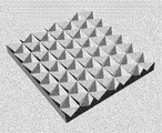
- G02B5/122—Reflex reflectors cube corner, trihedral or triple reflector type
- G02B5/124—Reflex reflectors cube corner, trihedral or triple reflector type plural reflecting elements forming part of a unitary plate or sheet
Definitions
- the present invention relates to an aerial image display system and an input system using this aerial image display system.
- an aerial image display device that displays an image in the air without a screen has been proposed, and as a promotional display with a high eye-catching effect or an input device that can touch-operate the image displayed in the air without touching the screen. Is expected to be utilized.
- An input device that can touch-operate the image displayed in the air is preferable in terms of hygiene because it does not touch the screen. Therefore, it is expected to be used as an input device touched by an unspecified number of people, an input device used in a medical field, and the like. Further, since the aerial image is difficult to be visually recognized from other than the front, for example, in an automated teller machine (ATM), it is expected to have an effect of preventing peeping from the surroundings when inputting a personal identification number.
- ATM automated teller machine
- Patent Document 1 describes an optical imaging device for forming an image of a real image of an object to be projected, in which P-polarization of a polarization axis parallel to a reference direction is transmitted and a polarization axis perpendicular to the reference direction is transmitted. After being reflected by a polarizing element that reflects S-polarization, a first phase difference element that converts S-polarization into circular polarization or elliptically polarization, a mirror that reflects light that has passed through the first retardation element, and a mirror.
- a second phase difference element that converts P polarization that has passed through the first phase difference element and has passed through the polarizing element into circular or elliptically polarized light, and a retroreflection that retroreflects the light that has passed through the second phase difference element.
- a plate and an optical imaging device comprising the plate are described.
- the photoimaging apparatus described in Patent Document 1 converts light from an object to be projected (light projection means) into S-polarized light and incidents it on a polarizing element, reflects the S-polarized light reflected by the polarizing element with a mirror, and emits light.
- the image of the object to be projected is displayed in the air by converting it into P-polarized light, transmitting the polarizing element, reflecting it on the retroreflector, converting the light into S-polarized light, and reflecting it on the visual recognition side by the deflector.
- An object of the present invention is to provide a thin aerial image display system capable of displaying an aerial image, and an input device capable of touch-operating an image displayed in the air without touching a screen.
- the present invention has the following configurations.
- Half mirror and It has a concave mirror, a Fresnel mirror, and a reflective member selected from the group consisting of retroreflective members.
- An aerial image display system in which a reflective member has a reflective polarizing element, and the reflective polarizing element constitutes a reflective surface of the reflective member.
- an image display device is provided.
- the aerial image display system according to [1] wherein the reflective member and the half mirror are arranged on the visual side of the image display device.
- the aerial image display system according to [2] further comprising a polarization separation element having a function of separating incident light into polarizations orthogonal to each other.
- the polarization separating element has a plurality of active retardation layers capable of switching the direction of the slow axis or the magnitude of retardation, and two regions in which at least one of the direction of the slow axis and the magnitude of retardation is different.
- it has either a pattern retardation layer, an active polarizing element capable of switching the direction of a transmission axis or an absorption axis, or a pattern polarizing element having a plurality of two types of regions having different directions of the transmission axis or the absorption axis.
- the reflective classifier is a reflective circular classifier. Further, it has an absorption type linear splitter and a retardation plate.
- the reflective classifier is a reflective circular classifier. Further, it has an absorption type linear splitter and a retardation plate.
- the reflective classifier is a reflective circular classifier. Further, it has an absorption type linear splitter and a retardation plate.
- the reflective classifier is a reflective circular classifier.
- the aerial image display system according to [9] which has an absorption type circular polarizing element on the visual side of the reflective member.
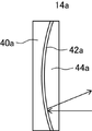
- the reflective member has a support and A reflective modulator is placed on the surface of the support, A coating layer having the same refractive index as the support is placed on the surface of the reflective polarizing element opposite to the support.
- a reflective modulator is placed on the surface of the support
- a coating layer having the same refractive index as the support is placed on the surface of the reflective polarizing element opposite to the support.
- One of [1] to [10] wherein the surface of the support opposite to the reflective splitter and the surface of the coating layer opposite to the reflective splitter are flat surfaces parallel to each other.
- [12] The aerial image display system according to any one of [1] to [11], wherein the reflective polarizing element includes a cholesteric liquid crystal layer.
- a thin aerial image display system capable of displaying an aerial image
- an input device capable of touch-operating an image displayed in the air without touching the screen.
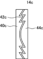
- FIG. 9 It is a figure which conceptually represents another example of the aerial image display system of this invention, and is the figure which showed the state which displays the aerial image. It is a figure which showed the state which the aerial image display system shown in FIG. 9 displays a non-floating image. It is a figure which conceptually represents another example of the aerial image display system of this invention, and is the figure which showed the state which displays the aerial image. It is a figure which showed the state which the aerial image display system shown in FIG. 11 displays a non-floating image. It is a figure which conceptually represents an example of a reflective member. It is a figure which conceptually represents another example of a reflective member. It is a top view which conceptually represents an example of a corner cube array. It is a perspective view which conceptually represents an example of a corner cube array. It is a figure which conceptually represents another example of a half mirror. It is a figure which conceptually represents the input system which has the aerial image display system of this invention.
- the numerical range represented by using "-" in the present specification means a range including the numerical values before and after "-" as the lower limit value and the upper limit value. Further, “orthogonal” and “parallel” with respect to an angle mean a range of a strict angle of ⁇ 10 °, and “same” and “different” with respect to an angle mean whether or not the difference is less than 5 °. Can be judged on the basis of.
- the "slow phase axis" means the direction in which the refractive index is maximized in the plane.
- the visible light is light having a wavelength visible to the human eye among electromagnetic waves, and indicates light having a wavelength range of 380 to 780 nm.
- the aerial image display system of the present invention is With a half mirror, It has a concave mirror, a Fresnel mirror, and a reflective member selected from the group consisting of retroreflective members.
- This is an aerial image display system in which the reflective member has a reflective polarizing element, and the reflective polarizing element constitutes a reflective surface of the reflective member.
- FIG. 1 is a diagram conceptually representing the aerial image display system of the present invention.
- the aerial image display system 10a shown in FIG. 1 has a half mirror 12 and a reflection member 14.
- the half mirror 12 is a semi-reflecting semi-transmissive half mirror that reflects a part of the incident light and transmits the rest.
- the reflective member 14 is a reflective member selected from the group consisting of a concave mirror, a Fresnel mirror, and a retroreflective member. Further, the reflective member 14 has a reflective polarizing element as a reflective layer, transmits light in one of the polarized states of the incident light, and reflects polarized light orthogonal to the polarized light. That is, the reflective member 14 is a semi-reflective semi-transmissive reflective member that reflects a part of the incident light and transmits the rest.
- the polarized light orthogonal to each other is the polarized light located on the back side of the Poincare sphere, such as the north pole point and the south pole point in the Poincare sphere.
- the polarizations orthogonal to each other are, for example, right-handed circularly polarized light and left-handed circularly polarized light in the case of circularly polarized light, and linearly polarized light orthogonal to each other in the case of linearly polarized light.
- the reflective classifier included in the reflective member 14 may be a reflective linear polarizing element or a reflective circular polarizing element.
- the reflective member 14 is one of a concave mirror, a Frenel mirror, and a retroreflective member, and when these reflective surfaces are composed of a reflective polarizing element, the effect of forming an image of reflected light in the air is exhibited. do.
- the configuration of the reflective member 14 will be described in detail later.
- the aerial image display system 10a is arranged between the object O and the user U with the reflective member 14 side facing the object O.
- the object O is irradiated with light
- the light is reflected on the surface of the object O.
- light is emitted from each point on the object O so as to spread in various directions.
- a part of the light reflected by the object O passes through the reflecting member 14.
- the reflective classifier included in the reflective member 14 is a reflective circular polarizing element
- the circularly polarized light component in the swirling direction opposite to the circularly polarized light component reflected by the reflecting member 14 among the incident light is the reflecting member. 14 is transmitted.
- the light transmitted through the reflecting member 14 is incident on the half mirror 12. Since the reflection by the half mirror 12 is specular reflection, the light is reflected so as to spread further. At that time, the circular polarization reflected by the half mirror 12 is converted into the circular polarization in the opposite turning direction.
- the circular polarization reflected by the half mirror 12 is incident on the reflecting member 14 again. Since the circular polarization reflected by the half mirror 12 is converted into circular polarization in the opposite turning direction, it is reflected by the reflecting member 14 (reflection type splitter). At that time, for example, when the reflecting member 14 is a retroreflective member, the traveling direction of the light reflected by the reflecting member 14 is opposite to the traveling direction from the half mirror 12 toward the reflecting member 14. It becomes the direction of. Therefore, the light reflected by the reflecting member 14 is condensed. The light reflected by the reflecting member 14 is incident on the half mirror 12, and a part of the light is transmitted through the half mirror 12 and condensed to form an image in the air.
- the light from the object O on the back side of the aerial image display system 10a as seen from the user U is imaged by the aerial image display system 10a in the space in front of the aerial image display system 10a.
- the aerial image V 1 of the object O can be displayed in the space on the front side of the aerial image display system 10a.
- the aerial image V 1 is a real image formed in the air.
- the aerial image display system 10a is configured such that the reflection member 14 is arranged on the object O side and the half mirror 12 is arranged on the user U side, but the present invention is not limited to this.
- the half mirror 12 may be arranged on the object O side, and the reflecting member 14 may be arranged on the user U side.
- the reflecting member 14 reflects one of the polarization components of the light transmitted through the half mirror 12 from the light from the object O.
- the reflecting member 14 is any of a concave mirror, a Fresnel mirror, and a retroreflective member, the reflected light is condensed. A part of the light reflected by the reflecting member 14 is reflected by the half mirror 12.
- the polarization state of the light reflected by the half mirror 12 is converted into orthogonal polarization.
- the light reflected by the half mirror 12 is incident on the reflecting member 14. Since the light reflected by the half mirror 12 is converted into polarized light whose polarization states are orthogonal to each other, the light is transmitted through the reflecting member 14 (reflection type polarizing element). Since the light transmitted through the reflective member 14 is condensed, the light is imaged in the space on the front side (user U side) of the aerial image display system 10a, and the aerial image V 1 of the object O is displayed. be able to.
- the aerial image display system 10a displays the aerial image V 1 of the object O arranged in the back of the aerial image display system 10a, but the present invention is not limited thereto. ..
- FIG. 2 shows another example of the aerial image display system of the present invention.
- the aerial image display system 10b shown in FIG. 2 includes an image display device 16, a reflection member 14, and a half mirror 12 in this order.
- the image display device 16 is a known image display device (display). Examples of the image display device include a liquid crystal display device, an organic electroluminescence display device, an LED (Light Emitting Diode) display device, a micro LED display device, and the like. When the aerial image may be a still image, the image display device may be a photograph provided with a backlight, a printed matter, or the like. In the following description, the organic electroluminescence display device is also referred to as an OLED. OLED is an abbreviation for "Organic Light Emitting Diode”.
- the half mirror 12 and the reflective member 14 are arranged on the visual recognition side of the image display device 16.
- the half mirror 12 and the reflecting member 14 are as described above.
- the image display device 16 irradiates light that becomes an image. At that time, as shown in FIG. 2, light is emitted from each point (each pixel) of the image display device so as to spread in various directions.
- the polarizing component transmitted by the reflective polarizing element is transmitted through the reflective member 14.
- the light transmitted through the reflecting member 14 is incident on the half mirror 12, and a part of the light is reflected by the half mirror 12. Since the reflection by the half mirror 12 is specular reflection, the light is reflected so as to spread further. At that time, the circular polarization reflected by the half mirror 12 is converted into the circular polarization in the opposite turning direction.
- the circular polarization reflected by the half mirror 12 is incident on the reflecting member 14 again. Since the circular polarization reflected by the half mirror 12 is converted into the circular polarization in the opposite turning direction, it is reflected by the reflecting member 14. At that time, for example, when the reflecting member 14 is a retroreflective member, the traveling direction of the light reflected by the reflecting member 14 is opposite to the traveling direction from the half mirror 12 toward the reflecting member 14. It becomes the direction of. Therefore, the light reflected by the reflecting member 14 is condensed. The light reflected by the reflecting member 14 is incident on the half mirror 12, and a part of the light is transmitted through the half mirror 12 and condensed to form an image in the air.
- the light emitted from the image display device 16 is imaged in the space on the reflective member 14 side (downstream side) of the aerial image display system 10b, whereby the aerial image display system 10b is formed.
- An aerial image V 1 of an image displayed by the image display device 16 can be displayed in the space on the downstream side of the image display device 16.
- the downstream is the downstream in the optical path of the image displayed (irradiated) by the image display device 16.
- the circularly polarized light component that is not reflected by the reflecting member 14 and that has passed through the half mirror 12 is reflected by the reflecting member 14 and the half mirror 12. It is irradiated from the aerial image display system 10b without being performed.
- This light image is visually recognized by the user U as a real image that does not float in the air (hereinafter referred to as a "non-floating image").
- the same image displayed by the image display device 16 is displayed as a non-floating image and an aerial image.
- the aerial image display system 10b is configured to be arranged in the order of the reflection member 14 and the half mirror 12 from the image display device 16 side, but the present invention is not limited to this, and the image display device 16 is not limited thereto.
- the half mirror 12 and the reflecting member 14 may be arranged in this order from the side.
- the reflecting member 14 reflects one of the polarization components of the light emitted from the image display device 16 that has passed through the half mirror 12.
- the reflecting member 14 is any of a concave mirror, a Fresnel mirror, and a retroreflective member, the reflected light is condensed. A part of the light reflected by the reflecting member 14 is reflected by the half mirror 12.
- the polarization state of the light reflected by the half mirror 12 is converted into orthogonal polarization.
- the light reflected by the half mirror 12 is incident on the reflecting member 14. Since the light reflected by the half mirror 12 is converted into polarized light whose polarization states are orthogonal to each other, the light is transmitted through the reflecting member 14 (reflection type splitter). Since the light transmitted through the reflective member 14 is condensed, the light is imaged in the space on the front side (user U side) of the aerial image display system 10b, and the aerial image V 1 of the object O is displayed. be able to.
- the aerial image display system of the present invention may further include a polarization separation element having a function of separating incident light into polarizations orthogonal to each other.
- FIG. 3 shows a diagram conceptually showing another example of the aerial image display system of the present invention.
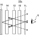
- the aerial image display system 10c shown in FIG. 3 includes an image display device 16, a reflection member 14, a half mirror 12, and a polarization splitting element 18 in this order.
- the polarization separation element 18 is an element that separates at least a part of the incident light into polarization orthogonal to each other.
- the polarized light orthogonal to each other is the polarized light located on the back side of the Poincare sphere, such as the north pole point and the south pole point in the Poincare sphere.
- circularly polarized light it is right-handed circularly polarized light and left-handed circularly polarized light
- linearly polarized light it is linearly polarized light that is orthogonal to each other.
- the half mirror 12, the reflection member 14, and the polarization splitting element 18 are arranged on the visual recognition side of the image display device 16.
- the half mirror 12, the reflecting member 14, and the image display device 16 are as described above.
- Such an aerial image display system 10c displays two types of images that are superimposed to form a multiplex image.
- one image R is observed by the user U through the half mirror 12, the reflecting member 14, and the polarization splitting element 18 without being reflected by the half mirror 12 and the reflecting member 14. (See the dashed arrow in FIG. 3). That is, the image R is an image in which the user U directly observes the image displayed by the image display device 16.
- this image R is also referred to as a non-floating image R.
- Another image V 1 is an image V 1 that is selectively transmitted by the reflecting member 14, reflected by the half mirror 12, and selectively reflected by the reflecting member 14, and is observed by the user U. .. That is, the image V 1 has an optical path that reciprocates between the half mirror 12 and the reflecting member 14 (see the solid arrow in FIG. 3).
- this image V 1 is also referred to as an aerial image V 1 .
- the optical path of the aerial image V 1 in the aerial image display system 10c is the same as the optical path of the aerial image V 1 of the aerial image display system 10b shown in FIG.
- the non-floating image R and the aerial image V 1 are separated into optical paths by the separation of the polarized light by the polarization separating element 18.
- FIG. 4 to 6 show an example of an image displayed by the aerial image display system 10c.
- FIG. 4 is an example of the non-floating image R displayed by the aerial image display system 10c.
- FIG. 5 is an example of the aerial image V1 displayed by the aerial image display system 10c.
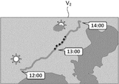
- FIG. 6 is an example of the superimposed image V 2 displayed by the aerial image display system 10c.
- the aerial image display system 10c superimposes and displays the non-floating image R and the aerial image V 1 .
- the aerial image display system 10c superimposes and displays the non-floating image R and the aerial image V 1 .
- such an aerial image display system of the present invention is used in a car navigation system, and a map image is displayed as a non-floating image R as conceptually shown in FIGS. 4 to 6, for example, and the aerial image V 1 As, additional information such as location information, weather and arrival time is displayed. At this time, the user U visually recognizes the additional information as if it were raised in front of the map image. As a result, the user U can discriminate between the map image and the additional information at a glance in the superimposed image to be observed, and can accurately and quickly find the information necessary for himself / herself.
- the image display device 16 alternately displays the image that becomes the non-floating image R and the image that becomes the aerial image V 1 in a time-division manner.
- the image display device 16 spatially divides the image that becomes the non-floating image R and the image that becomes the aerial image V 1 into stripes, and displays them in an alternately arranged manner.
- the polarization separation element 18 separates the incident light into polarized light orthogonal to each other by alternately performing polarization conversion or absorption of the incident light in time. ..
- the polarization separating element 18 spatially, for example, alternately performs polarization conversion or absorption of the incident light in a striped manner to obtain the incident light. Is separated into polarized light orthogonal to each other.
- the polarization separating element 18 is not reflected by the half mirror 12 and the reflecting member 14, but is reflected by the half mirror 12 and the reflection member 14.
- the polarized light transmitted through the member 14 is finally emitted to the visual recognition side, and the polarized light reflected between the half mirror 12 and the reflective member 14 and reciprocated once is finally absorbed or reflected to the visual viewing side. It works so that it is not emitted.
- the polarization separating element 18 reflects the polarized light between the half mirror 12 and the reflecting member 14 and reciprocates once, and the polarized light is emitted to the visual recognition side, and the half mirror 12 and the reflecting member 14 are displayed. It operates so that the polarized light transmitted through the half mirror 12 and the reflecting member 14 without being reflected by the 14 is absorbed or reflected and is not emitted to the visual recognition side.
- the polarization separating element 18 is not reflected by the half mirror 12 and the reflecting member 14 at the position where the non-floating image R is displayed, and the half mirror 12 is not reflected. And the polarized light transmitted through the reflective member 14 is finally emitted to the visual recognition side, and the polarized light reflected between the half mirror 12 and the reflective member 14 and reciprocated once is finally absorbed or reflected and visually recognized. It works so that it is not emitted to the side.
- the polarization separating element 18 reflects the polarized light between the half mirror 12 and the reflecting member 14 and reciprocates once, and the polarized light is emitted to the visual recognition side, and the half mirror 12 and the reflecting member 14 are displayed. It operates so that the polarized light transmitted through the half mirror 12 and the reflecting member 14 without being reflected by the 14 is absorbed or reflected and is not emitted to the visual recognition side.
- the aerial image display system 10c prevents the image to be displayed as the non-floating image R from being displayed as an aerial image, and the image to be displayed as the aerial image V 1 is displayed as a non-floating image. This can be prevented, and an image that becomes a non-floating image R can be displayed as a non-floating image R, and an image that becomes an aerial image V 1 can be displayed as a superposed image that can be appropriately visually recognized as an aerial image V 1 .
- the polarization separating element 18 is arranged on the visual recognition side with respect to the reflective member 14, but the present invention is not limited to this.
- the polarization separating element 18 may be arranged between the image display device 16 and the reflecting member 14. Alternatively, it may be arranged between the reflection member 14 and the half mirror 12.
- the aerial image display system 10c is configured to be arranged in the order of the reflection member 14 and the half mirror 12 from the image display device 16 side, but the present invention is not limited to this, and the image display device 16 is not limited thereto.
- the half mirror 12 and the reflecting member 14 may be arranged in this order from the side.
- FIG. 7 shows a diagram conceptually showing another example of the aerial image display system of the present invention.
- the aerial image display system 10d shown in FIG. 7 includes an image display device 16, an absorption-type linear splitter 20, a retardation layer 22, a reflection member 14, and a half mirror 12. Further, the aerial image display system 10d preferably has an absorption type circular splitter 32 on the visual side of the half mirror 12.
- the absorption type circular polarizing element 32 has a retardation layer 24 and an absorption type linear polarizing element 26.
- the reflective member 14 of the aerial image display system 10d has, as a reflective classifier, a reflective circular polarizing element that transmits circularly polarized light in one swirling direction and reflects circularly polarized light in the other swirling direction.
- the absorption type linear polarizing element 20 and the absorption type linear polarizing element 26 are known absorption type linear polarizing plates. Further, the retardation layer 22 and the retardation layer 24 are known retardation layers. As shown below, the retardation layer is basically a 1/4 wave plate because it converts linearly polarized light into circularly polarized light or circularly polarized light into linearly polarized light.
- the image display device 16 irradiates light that becomes an image (aerial image). At that time, as described above, the images are emitted from each point (each pixel) of the image display device so as to spread in various directions.
- the light emitted by the image display device 16 is converted into linear polarization in a certain direction through the absorption type linear polarizing element 20.
- the absorption type linear polarizing element 20 is assumed to transmit linear polarization in the vertical direction in the figure.
- this linearly polarized light is incident on the retardation layer 22.
- the retardation layer 22 converts the incident linearly polarized light into circularly polarized light. In the illustrated example, as an example, the retardation layer 22 converts the linear polarization in the vertical direction into the right circular polarization.
- This right circular polarization is incident on the reflecting member 14 having the reflective circular polarizing element.
- the reflective member 14 transmits the right polarized light
- the right polarized light incident on the reflective member 14 is transmitted without being reflected and incident on the half mirror 12.
- This right-handed circular polarization is incident on the half mirror 12, and a part of it is transmitted.
- the right-handed circular polarization transmitted through the half mirror 12 is incident on the absorption-type circular splitter 32.
- the absorption type circular polarizing element 32 absorbs the right circular polarization
- the absorption type circular splitter 32 has a retardation layer 24 and an absorption type linear splitter 26, and the right-handed circular polarization transmitted through the half mirror 12 is vertically directed by the retardation layer 24. Converted to linear polarization. Since the absorption type linear polarizing element 26 absorbs the linear polarization in the vertical direction, the linear polarization in the vertical direction is absorbed by the absorption type linear polarizing element 26.
- the remaining light of the right-handed circular polarization incident on the half mirror 12 is reflected by the half mirror 12. At that time, the right circular polarization is converted into the left circular polarization by the reflection.
- the left-handed circular polarization reflected by the half mirror 12 is incident on the reflecting member 14.
- the reflective circular polarizing element of the reflecting member 14 transmits the right circular polarization and reflects the left circular polarization
- the left circular polarization incident on the reflecting member 14 is reflected.
- the reflective member 14 is any of a concave mirror, a Fresnel mirror, and a retroreflective member, it reflects light so as to condense it.
- the left-handed circular polarization reflected by the reflecting member 14 is incident on the half mirror 12.
- a part of the left-handed circular polarization incident on the half mirror 12 is reflected and converted into right-handed circular polarization, passes through the reflective member 14, enters the retardation layer 22, and is converted into vertical linear polarization.
- This linearly polarized light passes through the absorption type linear polarizing element 20 and is absorbed by the surface of the image display device 16 or the like.
- the remaining left-handed circular polarization incident on the half mirror 12 passes through the half mirror 12.
- the left-handed circularly polarized light transmitted through the half mirror 12 is incident on the absorption-type circularly splitter 32. Since the absorption type circular polarizing element 32 absorbs the right circular polarization, the left circular polarization is transmitted.
- the absorption type circular polarizing element 32 has a retardation layer 24 and an absorption type linear polarizing element 26, and the left circular polarization transmitted through the half mirror 12 is in the vertical direction in the retardation layer 24.
- the aerial image display system 10d irradiates the user U side only with the light of the optical path that becomes the aerial image V 1 , and the image displayed by the image display device 16 is visually recognized as a non-floating image. It is preventing. As a result, the image displayed by the image display device 16 can be displayed as an aerial image V 1 .
- the aerial image display system 10d has, as a preferred embodiment, an absorption type circular splitter 32 on the visual recognition side of the half mirror 12.
- the absorption type circular splitter 32 By having the absorption type circular splitter 32, the stray light such as the right circular polarization component not reflected by the half mirror 12 can be absorbed by the absorption type circular splitter 32, and an unnecessary image caused by the stray light is visually recognized. It can be suppressed more reliably. Further, it is possible to prevent external light from being reflected on the surface of the aerial image display system 10d and causing so-called glare.
- the absorption axis of the absorption type linear polarizing element 20 and the absorption axis of the absorption type linear polarizing element 26 are orthogonal to each other.
- the above configuration is preferable because it is possible to further reduce stray light such as a polarizing component that cannot be completely reflected by the reflecting member 14.
- the configuration is not limited to the above, and for example, the absorption axis of the absorption type linear polarizing element 20 and the absorption axis of the absorption type linear polarizing element 26 may be parallel to each other.
- the magnitude of the phase difference of the retardation layer 22 and the magnitude of the phase difference of the retardation layer 24 match.
- the wavelength dispersibility of the retardation layer 22 and the wavelength dispersibility of the retardation layer 24 match, and it is more preferable that both are dedispersible.
- the inverse dispersibility means that the value of the phase difference at the wavelength increases as the wavelength increases. The above configuration is preferable because it is possible to further reduce stray light such as a polarizing component that cannot be completely reflected by the reflecting member 14.
- the members it is preferable to bond the members so that no air layer exists between the members. This is because the presence of an air layer may cause unnecessary reflection at the air interface of each member, or the reflective polarizing element may reflect polarized light that should not be reflected, which may cause stray light.
- the right circularly polarized light component that was not converted into the left circularly polarized light when reflected by the half mirror 12 is incident on the reflecting member 14 for the second time and is transmitted through the reflecting member 14.
- various known methods such as a method of laminating thin films having a specific refractive index and a film thickness, a method of sticking an AR film, a method of sticking a moth-eye film, and the like can be used. As described above, the same applies to each aspect after FIG. 8 regarding the reduction of reflection between each member.
- FIG. 8 shows a diagram conceptually showing another example of the aerial image display system of the present invention.
- the aerial image display system 10e shown in FIG. 8 includes an image display device 16, an absorption-type linear splitter 20, a retardation layer 22, a half mirror 12, and a reflection member 14. Further, as a preferred embodiment, the aerial image display system 10e has an absorption type circular polarizing element 32 on the visual side of the reflective member 14. In the illustrated example, the absorption type circular polarizing element 32 has a retardation layer 24 and an absorption type linear polarizing element 26.
- the reflective member 14 of the aerial image display system 10e has, as a reflective classifier, a reflective circular polarizing element that transmits circularly polarized light in one swirling direction and reflects circularly polarized light in the other swirling direction.
- the image display device 16 irradiates light that becomes an image (aerial image). At that time, as described above, the images are emitted from each point (each pixel) of the image display device so as to spread in various directions.
- the light emitted by the image display device 16 is converted into linear polarization in a certain direction through the absorption type linear polarizing element 20.
- the absorption type linear polarizing element 20 is assumed to transmit linear polarization in the vertical direction in the figure.
- this linearly polarized light is transmitted through the retardation layer 22 and converted into circularly polarized light.
- the retardation layer 22 converts the linear polarization in the vertical direction into the right circular polarization.
- this right circular polarization When this right circular polarization is incident on the half mirror 12, some light is reflected and converted into left circular polarization, and is incident on the retardation layer 22 in a direction orthogonal to the vertical direction (direction perpendicular to the paper surface). Converted to linear polarization. Since this linear polarization is linear polarization in a direction that does not pass through the absorption type linear polarizing element 20, it is absorbed by the absorption type linear polarizing element 20. On the other hand, the remaining light of the right-handed circular polarization incident on the half mirror 12 passes through the half mirror 12 and is incident on the reflecting member 14.
- the reflecting member 14 since the reflecting member 14 reflects the right-handed circular polarization, the right-handed circular polarization incident on the reflecting member 14 is reflected and incident on the half mirror 12. Further, since the reflective member 14 is any of a concave mirror, a Fresnel mirror, and a retroreflective member, it reflects light so as to condense it.
- a part of the right-handed circular polarization incident on the half mirror 12 is reflected. At that time, the right circular polarization is converted into the left circular polarization by the reflection. On the other hand, the remaining light of the right-handed circular polarization incident on the half mirror 12 passes through the half mirror 12.
- the right-handed circular polarization transmitted through the half mirror 12 is converted into linear polarization by the retardation layer 22, passes through the absorption-type linear splitter 20, and is absorbed by the surface of the image display device 16 or the like.
- the left-handed circular polarization reflected by the half mirror 12 is incident on the reflecting member 14. Since the reflective circular polarizing element of the reflective member 14 reflects the right circular polarization, the left circular polarization is transmitted.
- the left circularly polarized light transmitted through the reflecting member 14 is incident on the absorption type circular polarizing element 32.
- the absorption type circular polarizing element 32 transmits while converting the circular polarization in the same turning direction as the circular polarization transmitted by the reflecting member 14 into linear polarization. Therefore, in the illustrated example, the absorption type circular polarizing element 32 transmits the left circular polarization. Specifically, the left circular polarization transmitted through the reflective member 14 is incident on the retardation layer 24.
- the retardation layer 24 converts the incident left circular polarization into left-right linear polarization.
- the linearly polarized light transmitted through the retardation layer 24 is incident on the absorption type linear polarizing element 26.
- the absorption type linear polarizing element 26 transmits linear polarization in the left-right direction.
- the absorption type circular polarizing element 32 transmits the circular polarization in the same turning direction as the circular polarization transmitted by the reflecting member 14 while converting it into linear polarization.
- the aerial image display system 10e irradiates only the light of the optical path that becomes the aerial image V 1 to the user U side, and the image displayed by the image display device 16 is visually recognized as a non-floating image. It is preventing. As a result, the image displayed by the image display device 16 can be displayed as an aerial image V 1 .
- the aerial image display system 10e has, as a preferred embodiment, an absorption type circular polarizing element 32 on the visual recognition side of the reflective member 14.
- the absorption type circular polarizing element 32 By having the absorption type circular polarizing element 32, the stray light such as the right circular polarization component that could not be completely reflected by the reflective member 14 can be absorbed by the absorption type circular polarizing element 32, and an unnecessary image caused by the stray light can be visually recognized. It can be more reliably suppressed. Further, it is possible to prevent external light from being reflected on the surface of the aerial image display system 10e and causing so-called glare.
- the retardation layer 22 is preferably reverse-dispersible.
- the retardation layer 22 is dedispersible, the light incident on the reflective member 14 becomes more ideal circularly polarized light, and stray light can be further reduced, which is preferable.
- the retardation layer 24 is also preferably reverse-dispersible.
- FIG 9 and 10 show conceptual representations of another example of the aerial image display system of the present invention.
- the aerial image display system 10f shown in FIGS. 9 and 10 includes an image display device 16, an absorption type linear splitter 20, a retardation layer 22, a reflection member 14, a half mirror 12, and a polarization splitting element 18.
- the reflective member 14 of the aerial image display system 10f has, as a reflective classifier, a reflective circular polarizing element that transmits circularly polarized light in one swirling direction and reflects circularly polarized light in the other swirling direction.
- the polarization separating element 18 has an absorption type linear polarizing element 28 and a retardation layer 30.
- the absorption type linear polarizing element 28 is an active polarizing element capable of switching the direction of the transmission axis (absorption axis), or a region in which the direction of the transmission axis (absorption axis) is different.
- the polarization separating element 18 When the polarization separating element 18 has an active polarizing element or an active retardation layer, the polarization separating element 18 is orthogonal to a state in which one of the incident light is transmitted and the polarization orthogonal to the one is transmitted. It is possible to switch between a state in which the polarization is transmitted and one of the polarizations is absorbed.
- a polarization separation element 18 is also referred to as a time-division polarization separation element 18.
- the image display device 16 time-divides the non-floating image R and the aerial image V 1 in accordance with the switching operation of the polarization separation element 18. And display alternately.
- the polarization separating element 18 transmits only the polarized light passing through the optical path that becomes the non-floating image R, and the aerial image V 1
- the polarization separating element 18 displays the aerial image V.
- the aerial image display system 10f alternately displays the non-floating image R and the aerial image V 1 to display the superimposed image V 2 in which the non-floating image R and the aerial image V 1 are superimposed.
- the polarization separating element 18 when the polarization separating element 18 has a pattern polarizing element or a pattern retardation layer, the polarization separating element 18 is a region of the incident light that transmits one of the polarized light and absorbs the polarized light orthogonal to the polarized light. It has a plurality of regions that transmit orthogonally polarized light and absorb one of the polarized light.
- a polarization separation element 18 is also referred to as a spatial division polarization separation element 18.
- the image display device 16 sets the non-floating image R and the aerial image V 1 in accordance with the region division configuration of the polarization separation element 18. Display by dividing the space. For example, when the polarization separating element 18 alternately has a region that transmits one polarization and a region that transmits the other polarization in a striped manner, the image display device 16 has a non-floating image R and an aerial image V 1 . And are spatially divided into stripes and displayed alternately.
- the polarization separating element 18 transmits only the polarized light passing through the optical path that becomes the non-floating image R, and the aerial image V 1
- the polarization separating element 18 displays the aerial image V 1
- Only the aerial image V 1 is displayed by transmitting only the polarized light passing through the optical path to be a non-floating image R and not transmitting the polarized light passing through the optical path to be a non-floating image R.
- the aerial image display system 10f displays a superposed image V 2 in which the non-floating image R and the aerial image V 1 are superimposed by displaying the non-floating image R and the aerial image V 1 for each region.
- FIG. 9 shows the timing of displaying the aerial image V 1 or the state of the region for displaying the aerial image V 1 in the aerial image display system 10f. The operation of the aerial image display system 10f in this state will be described.
- the image display device 16 irradiates light that becomes an image (aerial image). At that time, as described above, the images are emitted from each point (each pixel) of the image display device so as to spread in various directions.
- the light emitted by the image display device 16 is converted into linear polarization in a certain direction through the absorption type linear polarizing element 20.
- the absorption type linear polarizing element 20 is assumed to transmit linear polarization in the vertical direction in the figure.
- this linearly polarized light is incident on the retardation layer 22.
- the retardation layer 22 converts the incident linearly polarized light into circularly polarized light. In the illustrated example, as an example, the retardation layer 22 converts the linear polarization in the vertical direction into the right circular polarization.
- This right circular polarization is incident on the reflective member 14.
- the reflective circular polarizing element of the reflecting member 14 transmits the right circular polarization and reflects the left circular polarization, the right polarization incident on the reflecting member 14 is transmitted without being reflected and is half. It is incident on the mirror 12.
- This right-handed circular polarization is incident on the half mirror 12, and a part of it is transmitted.
- the right-handed circular polarization transmitted through the half mirror 12 is incident on the polarization splitting element 18.
- the polarization separating element 18 since the polarization separation element 18 absorbs the right circular polarization, the right circular polarization incident on the polarization separation element 18 is absorbed.
- the polarization separating element 18 has a retardation layer 30 and an absorption type linear splitter 28, and the right-handed circular polarization transmitted through the half mirror 12 is vertically linearly polarized in the retardation layer 30. Is converted to. Since the absorption type linear polarizing element 28 absorbs the linear polarization in the vertical direction, the linear polarization in the vertical direction is absorbed by the absorption type linear polarizing element 28.
- the remaining light of the right-handed circular polarization incident on the half mirror 12 is reflected by the half mirror 12. At that time, the right circular polarization is converted into the left circular polarization by the reflection.
- the left-handed circular polarization reflected by the half mirror 12 is incident on the reflecting member 14.
- the reflective circular polarizing element of the reflecting member 14 reflects the left circular polarization
- the left circular polarization incident on the reflecting member 14 is reflected.
- the reflective member 14 is any of a concave mirror, a Fresnel mirror, and a retroreflective member, it reflects light so as to condense it.
- the left-handed circular polarization reflected by the reflecting member 14 is incident on the half mirror 12.
- a part of the left circular polarization incident on the half mirror 12 is reflected and converted into a right circular polarization, and is incident on the reflecting member 14.
- This right-handed circular polarization passes through the reflective member 14, is converted into linear polarization by the retardation layer 22, passes through the absorption-type linear polarizing element 20, and is absorbed by the surface of the image display device 16 or the like.
- the remaining light of the left-handed circular polarization incident on the half mirror 12 passes through the half mirror 12.
- the left-handed circular polarization transmitted through the half mirror 12 is incident on the polarization splitting element 18. Since the polarization separating element 18 absorbs the right circular polarization, the left circular polarization is transmitted.
- the polarization separating element 18 has a retardation layer 30 and an absorption type linear splitter 28, and the left-handed circular polarization transmitted through the half mirror 12 is linearly polarized in the left-right direction by the retardation layer 30. Is converted to. Since the absorption type linear polarizing element 28 absorbs the linear polarization in the vertical direction, the linear polarization in the left-right direction passes through the absorption type linear polarizing element 28.
- the aerial image display system 10f irradiates the user U side only with the light of the optical path that becomes the aerial image V 1 , and the image displayed by the image display device 16 is visually recognized as a non-floating image. It is preventing. As a result, the image displayed by the image display device 16 can be displayed as an aerial image V 1 .
- the retardation layer 22 is preferably reverse-dispersible.
- the retardation layer 22 is dedispersible, the light incident on the reflective member 14 becomes more ideal circularly polarized light, and stray light can be further reduced, which is preferable. Further, for the same reason, it is preferable that the retardation layer 30 is also reverse-dispersible.
- FIG. 10 shows the timing of displaying the non-floating image R or the state of the region for displaying the non-floating image R in the aerial image display system 10f. The operation of the aerial image display system 10f in this state will be described.
- the image display device 16 irradiates light that becomes an image (non-floating image). At that time, as described above, the images are emitted from each point (each pixel) of the image display device so as to spread in various directions.
- the light emitted by the image display device 16 is converted into linear polarization in a certain direction through the absorption type linear polarizing element 20.
- the absorption type linear polarizing element 20 transmits linear polarization in the vertical direction in the figure.
- this linearly polarized light is incident on the retardation layer 22.
- the retardation layer 22 converts the incident linearly polarized light into circularly polarized light. As described above, in the illustrated example, as an example, the retardation layer 22 converts the linear polarization in the vertical direction into the right circular polarization.
- This right circular polarization is incident on the reflective member 14.
- the reflective circular polarizing element of the reflecting member 14 transmits the right circular polarization and reflects the left circular polarization, the right polarization incident on the reflecting member 14 is transmitted without being reflected and is half. It is incident on the mirror 12.
- This right-handed circular polarization is incident on the half mirror 12, and a part of it is transmitted.
- the right-handed circular polarization transmitted through the half mirror 12 is incident on the polarization splitting element 18.
- the polarization separation element 18 since the polarization separation element 18 transmits the right circular polarization, the right circular polarization is transmitted through the polarization separation element 18 and emitted from the aerial image display system 10f.
- the right circular polarization is transmitted through the retardation layer 30 of the polarization separation element 18 and converted into linear polarization in the left-right direction. That is, in FIGS. 9 and 10, the retardation layer 30 is an active retardation layer or a pattern retardation layer, and in the state shown in FIG. 10, the retardation layer 30 is slower than the state shown in FIG.
- the right-handed circular polarization transmitted through the retardation layer 30 with different axial directions is converted into linear polarization in the left-right direction orthogonal to the state shown in FIG.
- the linear polarization in the left-right direction converted by the retardation layer 30 is incident on the absorption-type linear polarizing element 28. Since the absorption type linear polarizing element 28 absorbs the linear polarization in the vertical direction, the linear polarization in the left-right direction passes through the absorption type linear polarizing element 28.
- a part of the right-handed circular polarization reflected by the half mirror 12 is converted into a left-handed circular polarization by the reflection.
- the left-handed circular polarization reflected by the half mirror 12 is incident on the reflecting member 14. Since the reflective circular polarizing element of the reflecting member 14 transmits the right circular polarization and reflects the left circular polarization, the left circular polarization is reflected.
- the reflected left-handed circular polarization is incident on the half mirror 12.
- a part of the light incident on the half mirror 12 passes through the half mirror 12.
- the transmitted left circular polarization is incident on the polarization separating element 18. Since the polarization separating element 18 transmits the right circular polarization, the left circular polarization is absorbed. Specifically, the left circular polarization is transmitted through the retardation layer 30 of the polarization separating element 18 and converted into linear polarization in the vertical direction, while the absorption type linear polarizing element 28 absorbs the linear polarization in the vertical direction. Therefore, this vertical linear polarization is absorbed by the absorption type linear polarizing element 28.
- the left circularly polarized light reflected by the half mirror 12 is converted into right circularly polarized light by reflection, transmitted through the reflecting member 14, linearly polarized light by the retardation layer 22, and transmitted through the absorption type linear polarizing element 20. Therefore, it is absorbed by the surface of the image display device 16 or the like.
- the aerial image display system 10f displays the non-floating image R, or in the region where the non-floating image R is displayed, only the light of the optical path that becomes the non-floating image R is irradiated to the user U side.
- the image displayed by the image display device 16 is prevented from being visually recognized as an aerial image. This prevents the image displayed by the image display device 16 as the non-floating image R from being displayed as an aerial image, and can be displayed only as the non-floating image R.
- the polarization separating element 18 transmits only the polarized light passing through the optical path that becomes the non-floating image R, and is in the air.
- the polarization separating element 18 is displayed at the timing or region where the image display device 16 displays the aerial image V 1 .
- the aerial image display system 10f displays a superposed image V 2 in which the non-floating image R and the aerial image V 1 are superimposed by displaying the non-floating image R and the aerial image V 1 in a time-division or spatial division.
- FIGS. 9 to 10 are examples in which the polarization splitting element 18 is arranged on the viewing side of the half mirror 12 and the reflective splitter.
- FIG 11 and 12 are diagrams conceptually showing another example of the aerial image display system of the present invention.
- the aerial image display system 10g shown in FIGS. 11 and 12 includes an image display device 16, a polarization splitting element 18, a half mirror 12, and a reflecting member 14. Further, the aerial image display system 10g has, as a preferred embodiment, an absorption type circular polarizing element 32 on the visual recognition side with respect to the reflective member 14.
- FIG. 11 shows the timing of displaying the aerial image V 1 or the state of the region for displaying the aerial image V 1 in the aerial image display system 10g.
- the operation of the aerial image display system 10g in this state will be described.
- the image display device 16 irradiates light that becomes an image (aerial image). At that time, as described above, the images are emitted from each point (each pixel) of the image display device so as to spread in various directions.
- the light emitted by the image display device 16 is converted into linear polarization in a certain direction through the absorption type linear polarizing element 28 of the polarization separating element 18.
- the absorption type linear polarizing element 28 is assumed to transmit linear polarization in the vertical direction in the figure.
- this linearly polarized light is transmitted through the retardation layer 30 of the polarization separating element 18 and converted into circularly polarized light.
- the retardation layer 30 is assumed to convert the linear polarization in the vertical direction into the right circular polarization.
- the right circular polarization When the right circular polarization is incident on the half mirror 12, a part of the light is reflected and converted into left circular polarization, and is incident on the retardation layer 30 and converted into linear polarization in the left-right direction. Since this linear polarization is linear polarization in a direction that does not pass through the absorption type linear polarizing element 28, it is absorbed by the absorption type linear polarizing element 28. On the other hand, the remaining light of the right-handed circular polarization incident on the half mirror 12 passes through the half mirror 12 and is incident on the reflecting member 14. In the illustrated example, since the reflective circular splitter of the reflecting member 14 reflects the right circular polarization, the right circular polarization incident on the reflecting member 14 is reflected and incident on the half mirror 12. Further, since the reflective member 14 is any of a concave mirror, a Fresnel mirror, and a retroreflective member, it reflects light so as to condense it.
- a part of the light incident on the half mirror 12 is reflected. At that time, the right circular polarization is converted into the left circular polarization by the reflection. On the other hand, the remaining light of the right-handed circular polarization incident on the half mirror 12 passes through the half mirror 12.
- the right-handed circular polarization transmitted through the half mirror 12 is converted into linear polarization by the retardation layer 30, passes through the absorption-type linear splitter 28, and is absorbed by the surface of the image display device 16 or the like.
- the left-handed circular polarization reflected by the half mirror 12 is incident on the reflecting member 14. Since the reflective circular polarizing element of the reflective member 14 reflects the right circular polarization, the left circular polarization is transmitted.
- the left circularly polarized light transmitted through the reflecting member 14 is incident on the absorption type circular polarizing element 32.
- the absorption type circular polarizing element 32 transmits while converting the circular polarization in the same turning direction as the circular polarization transmitted by the reflecting member 14 into linear polarization. Therefore, in the illustrated example, the absorption type circular polarizing element 32 transmits the left circular polarization. Specifically, the left circular polarization transmitted through the reflective member 14 is incident on the retardation layer 24.
- the retardation layer 24 converts the incident left circular polarization into left-right linear polarization.
- the linearly polarized light transmitted through the retardation layer 24 is incident on the absorption type linear polarizing element 26.
- the absorption type linear polarizing element 26 transmits linear polarization in the left-right direction.
- the absorption type circular polarizing element 32 transmits the circular polarization in the same turning direction as the circular polarization transmitted by the reflecting member 14 while converting it into linear polarization.
- the aerial image display system 10g displays only the light of the optical path that becomes the aerial image V 1 at the timing when the image display device 16 displays the aerial image V 1 or in the region where the aerial image V 1 is displayed. It irradiates the user U side to prevent the image displayed by the image display device 16 from being visually recognized as a non-floating image. This prevents the image displayed by the image display device 16 as an aerial image V 1 from being displayed as a non-floating image, and can be displayed only as an aerial image V 1 .
- the aerial image display system 10g has, as a preferred embodiment, an absorption type circular polarizing element 32 on the visual recognition side of the reflective member 14.
- the absorption type circular polarizing element 32 By having the absorption type circular polarizing element 32, the stray light such as the right circular polarization component that could not be completely reflected by the reflective member 14 can be absorbed by the absorption type circular polarizing element 32, and an unnecessary image caused by the stray light can be visually recognized. It can be more reliably suppressed. Further, it is possible to prevent external light from being reflected on the surface of the aerial image display system 10g and causing so-called glare.
- the retardation layer 30 is preferably reverse-dispersible.
- the retardation layer 30 is dedispersible, the light incident on the reflective member 14 becomes more ideal circularly polarized light, and stray light can be further reduced, which is preferable.
- the retardation layer 24 is also preferably reverse-dispersible.
- FIG. 12 shows the timing of displaying the non-floating image R or the state of the region for displaying the non-floating image R in the aerial image display system 10g. The operation of the aerial image display system 10g in this state will be described.
- the image display device 16 irradiates light that becomes an image (non-floating image). At that time, as described above, the images are emitted from each point (each pixel) of the image display device so as to spread in various directions.
- the light emitted by the image display device 16 is converted into linear polarization in a certain direction through the absorption type linear polarizing element 28 of the polarization separating element 18.
- the absorption type linear polarizing element 28 transmits linear polarization in the vertical direction in the figure.
- this linearly polarized light is transmitted through the retardation layer 30 of the polarization separating element 18 and converted into circularly polarized light.
- the retardation layer 30 converts the linear polarization in the vertical direction into the left circular polarization. That is, in FIGS. 11 and 12, the retardation layer 30 is an active retardation layer or a pattern retardation layer, and in the state shown in FIG. 12, the retardation layer 30 is slower than the state shown in FIG. The orientations of the axes are different, and the linear polarization in the vertical direction transmitted through the retardation layer 30 is converted into left circular polarization, which is the opposite of the state shown in FIG.
- this left-handed circular polarization When this left-handed circular polarization is incident on the half mirror 12, a part of the light is reflected and converted into right-handed circular polarization, and then incident on the retardation layer 30 and converted into linear polarization in the left-right direction. Since this linear polarization is linear polarization in a direction that does not pass through the absorption type linear polarizing element 28, it is absorbed by the absorption type linear polarizing element 28.
- the remaining light of the left circularly polarized light incident on the half mirror 12 passes through the half mirror 12 and is incident on the reflecting member 14, but turns in the opposite direction to the circularly polarized light reflected by the reflective circular polarizing element of the reflecting member 14. Since it is circularly polarized in the direction, it passes through the reflective member 14.
- the left circular polarization transmitted through the reflective member 14 is incident on the absorption type circular polarizing element 32.
- the absorption type circular splitter 32 converts the incident left circular polarization into left-right linear polarization and transmits it.
- the aerial image display system 10g displays the non-floating image R, or in the region where the non-floating image R is displayed, only the light of the optical path that becomes the non-floating image R is irradiated to the user U side.
- the image displayed by the image display device 16 is prevented from being visually recognized as an aerial image. This prevents the image displayed by the image display device 16 as the non-floating image R from being displayed as an aerial image, and can be displayed only as the non-floating image R.
- the polarization separating element 18 transmits only the polarized light passing through the optical path that becomes the non-floating image R, and is in the air.
- the polarization separating element 18 is displayed at the timing or region where the image display device 16 displays the aerial image V 1 .
- Only the aerial image V 1 is displayed by transmitting only the polarized light passing through the optical path that becomes the aerial image V 1 and not transmitting the polarized light passing through the optical path that becomes the non-floating image R.
- the aerial image display system 10g displays a superposed image V 2 in which the non-floating image R and the aerial image V 1 are superimposed by displaying the non-floating image R and the aerial image V 1 in a time-division or spatial division.
- FIGS. 11 to 12 are examples in which the polarization splitting element 18 is arranged between the image display device 16 and the half mirror 12.
- the reflective member 14 is configured to have a reflective circular polarizing element, but the present invention is not limited to this, and the reflective member 14 is configured to have a reflective linear polarizing element. May be good.
- the reflective member 14 has a reflective linear splitter, the light incident on the reflective member 14 is linearly polarized, and the light incident on the half mirror 12 is linearly polarized, so that the retardation layer or the like is used. The arrangement may be changed as appropriate.
- a half mirror is a conventionally known half mirror that transmits about half of the incident light and reflects the other half.
- the transmittance of the half mirror is preferably 50 ⁇ 30%, more preferably 50 ⁇ 10%, and most preferably 50%.
- the half mirror is made of a transparent resin such as polyethylene terephthalate (PET), cycloolefin polymer (COP), polymethyl methacrylate (PMMA), or a metal such as silver or aluminum on a substrate made of glass or the like. It is a configuration having a reflective layer made of the like.
- a reflective layer made of a metal such as silver or aluminum is formed on the surface of the base material by thin film deposition or the like.
- the thickness of the reflective layer is preferably 1 to 20 nm, more preferably 2 to 10 nm, still more preferably 3 to 6 nm.
- the reflective member has a reflective classifier, and the reflective classifier constitutes a reflective surface of the reflective member. Of the incident light, the light in one of the polarized states is transmitted and is orthogonal to the polarized light. It reflects polarized light. Further, the reflective member has a configuration selected from the group consisting of a concave mirror, a Fresnel mirror, and a retroreflective member. 13 to 15 each show a diagram conceptually showing an example of the reflective member.
- FIG. 13 is a diagram showing a cross section of an example of a reflective member which is a concave mirror.
- the reflective member 14a shown in FIG. 13 has a transparent support 40a having a concave surface, a reflective polarizing element 42a formed on the concave surface of the support 40a, and a surface opposite to the support 40a of the reflective polarizing element 42a. It has a coating layer 44a laminated on the surface of the coating layer 44a.
- the support 40a is made of glass, triacetyl cellulose (TAC), polyethylene terephthalate (PET), polycarbonate, polyvinyl chloride, acrylic, polyolefin or the like, and one surface (concave surface) is one of a spherical surface or a free surface. It has a recess with a cut-out part.
- TAC triacetyl cellulose
- PET polyethylene terephthalate
- PET polycarbonate
- polyvinyl chloride acrylic
- polyolefin or the like one surface (concave surface) is one of a spherical surface or a free surface. It has a recess with a cut-out part.
- a reflective polarizing element 42a is laminated on the concave surface of the support 40a.
- the reflective polarizing element 42a has a substantially constant thickness and is laminated along the recess of the support 40a. That is, the reflective polarizing element 42a has a concavely curved shape.
- the reflective member 14a transmits light in one of the polarized states by the reflective polarizing element 42a, reflects the polarized light orthogonal to the polarized light, and reflects the reflected light due to the concave shape of the reflective polarizing element 42a. It has a function of condensing light.
- the reflective splitter is basically a reflective linear or circular modulator.
- the reflection type linear polarizing element is a substituent that transmits linear polarization in a certain direction and reflects linear polarization in a direction orthogonal to the linear polarization.
- the reflective linear polarizing element a film obtained by stretching a dielectric multilayer film as described in Japanese Patent Application Laid-Open No. 2011-053705, and as described in Japanese Patent Application Laid-Open No. 2015-028656.
- a wire grid type deflector and the like are exemplified.
- a commercially available product can also be preferably used as the reflective linear deflector. Examples of the commercially available reflective linear deflector include a reflective deflector manufactured by 3M (trade name: APF) and a wire grid splitter manufactured by AGC (trade name: WGF).
- the reflective circularly polarized light is a splitter that transmits right-handed circularly polarized light or left-handed circularly polarized light and reflects circularly polarized light whose turning direction is opposite to that of the transmitted circularly polarized light.
- a reflective circular polarizing element having a cholesteric liquid crystal layer is exemplified as the reflective circular polarizing element.
- the cholesteric liquid crystal layer is a liquid crystal phase in which a cholesterically oriented liquid crystal phase (cholesteric liquid crystal phase) is fixed.
- the cholesteric liquid crystal layer has a spiral structure in which liquid crystal compounds are spirally swirled and stacked, and a configuration in which liquid crystal compounds are spirally rotated once (360 ° rotation) and stacked is spiral 1.
- the pitch spiral pitch
- the liquid crystal compound that swirls in a spiral shape has a structure in which a plurality of pitches are laminated.
- the cholesteric liquid crystal layer reflects right-handed or left-handed circularly polarized light in a specific wavelength range and transmits other light depending on the length of the spiral pitch and the swirling direction (sense) of the spiral by the liquid crystal compound. do.
- the reflective circular polarizing element is, for example, a cholesteric liquid crystal layer having a center wavelength of reflection selective for red light, a center of reflection selective for green light. It may have a plurality of cholesteric liquid crystal layers such as a cholesteric liquid crystal layer having a wavelength and a cholesteric liquid crystal layer having a central wavelength of reflection selective for blue light.
- the cholesteric liquid crystal layer may be directly formed on the support 40a having a concave surface, or may be formed on the temporary support and then attached onto the concave surface of the support 40a. Further, an alignment film for orienting the liquid crystal compound in the cholesteric liquid crystal layer may be provided between the support 40a and the cholesteric liquid crystal layer.
- the thickness of the reflective classifier is such that the polarized light to be reflected can be sufficiently reflected and the polarized light to be transmitted can be sufficiently transmitted depending on the type of the reflective classifier and the like. It may be adjusted as appropriate.
- the reflective member 14a of the illustrated example has, as a preferred embodiment, a covering layer 44a laminated on the surface of the reflective polarizing element 42a opposite to the support 40a.
- the coating layer 44a is preferably transparent. Further, it is preferably made of a material having substantially the same refractive index as the support 40a. Further, it is preferable that the surface of the support 40a on the opposite side of the reflective splitter 42a and the surface of the covering layer 44a on the opposite side of the reflective splitter 42a are flat surfaces parallel to each other.
- the reflective member 14a has a coating layer 44a having substantially the same refractive index as the support 40a, and the surfaces of the support 40a and the coating layer 44a are made flat surfaces parallel to each other to make the reflective member 14a. It is possible to prevent the transmitted light from being bent due to the influence of the concave surface of the support 40a, and it is possible to prevent the image of the light transmitted through the reflective member 14a from being enlarged or reduced. Thereby, in the aerial image display system of the present invention, it is possible to prevent the non-floating image and / or the aerial image from being enlarged, reduced, or distorted.
- the refractive index of the support 40a and the refractive index of the coating layer 44a do not have to be exactly the same as long as the above effect is obtained, and may differ within the range in which the effect is exhibited.
- the difference between the refractive index of the support 40a and the refractive index of the coating layer 44a is preferably 0.1 or less, more preferably 0.05 or less, still more preferably 0.01 or less.
- FIG. 14 is a diagram showing a cross section of an example of a reflective member which is a retroreflective member.
- the reflective member 14b shown in FIG. 14 is a transparent support 40b having a corner cube array formed on its surface, a reflective polarizing element 42b formed on the corner cube array of the support 40b, and a support of the reflective polarizing element 42b. It has a coating layer 44b laminated on the surface opposite to the body 40b.
- FIG. 15 shows a plan view of an example of a corner cube array
- FIG. 16 shows a perspective view of an example of a corner cube array
- the corner cube array has a structure in which a large number of three-sided mirrors (also referred to as corner cube prisms) in which three-sided mirrors intersect at right angles are arranged on a plane.
- One size of the three-sided mirror is preferably smaller than 1 mm on a side from the viewpoint of improving the resolution of the aerial image.
- Light incident on one of the three-sided mirrors of the corner cube array is sequentially reflected by each of the three mirror surfaces and emitted in the opposite direction parallel to the incident direction. That is, it is retroreflected.
- the support 40b is made of glass, triacetyl cellulose (TAC), polyethylene terephthalate (PET), polycarbonate, polyvinyl chloride, acrylic, polyolefin or the like, and has a corner cube array known as a retroreflective member.
- a reflective polarizing element 42b is laminated on the corner cube array of the support 40b.
- the reflective polarizing elements 42b have a substantially constant thickness and are laminated along the surface shape of the corner cube array of the support 40b. That is, the reflective polarizing element 42b functions as a reflective layer of the corner cube array.
- the reflective classifier 42b is a conventionally known reflective circular polarizing element or a reflective linear polarizing element, similar to the reflective classifier 42a of the reflective member 14a, except that the shape is different.
- the reflective member 14a has a function of transmitting light in one of the polarized states by the reflective polarizing element 42a, reflecting the polarized light orthogonal to the polarized light, and retroreflecting the reflected light.
- the reflective member 14b of the illustrated example also has, as a preferred embodiment, a covering layer 44b laminated on the surface of the reflective polarizing element 42b opposite to the support 40b.
- the surface of the support 40b on the opposite side of the reflective splitter 42b and the surface of the covering layer 44b on the opposite side of the reflective splitter 42b are flat surfaces parallel to each other.
- the coating layer 44b is preferably transparent, and the difference between the refractive index of the support 40b and the refractive index of the coating layer 44b is preferably 0.1 or less, more preferably 0.05 or less, and preferably 0.01 or less. More preferred.
- the reflective member 14b is a retroreflective member made of a corner cube array, but the present invention is not limited to this, and the reflective surface of the glass bead type retroreflective member is a reflective deflector. May be.
- FIG. 17 is a cross-sectional view showing an example of a reflective member of a Fresnel mirror.
- the reflective member 14c shown in FIG. 17 includes a transparent support 40c having a Fresnel lens-shaped groove, a reflective polarizing element 42c formed on the surface of the support 40c on which a Fresnel lens is formed, and a reflective polarizing element 42c. It has a coating layer 44c laminated on the surface opposite to the support 40c of the above.
- the support 40c is made of glass, triacetyl cellulose (TAC), polyethylene terephthalate (PET), polycarbonate, polyvinyl chloride, acrylic, polyolefin, etc., and has a known Fresnel lens shape on one surface.
- TAC triacetyl cellulose
- PET polyethylene terephthalate
- PET polycarbonate
- polyvinyl chloride acrylic, polyolefin, etc.
- Fresnel lens shape on one surface.
- a reflective polarizing element 42c is laminated on the surface of the support 40c on which a Fresnel lens-shaped groove is formed.
- the reflective polarizing element 42c has a substantially constant thickness and is laminated along the Fresnel lens shape of the support 40a. That is, the reflective polarizing element 42c has a Fresnel lens shape.
- the reflective classifier 42c is a conventionally known reflective circular polarizing element or a reflective linear polarizing element, similar to the reflective classifier 42a of the reflective member 14a, except that the shape is different.
- the reflective member 14c transmits light in one of the polarized states by the reflective polarizing element 42c, reflects the polarized light orthogonal to the polarized light, and the reflective polarizing element 42c has a Frenel lens shape, so that the Frenel mirror is used. It has the function of condensing the reflected light by the same function as a concave mirror.
- the reflective member 14c of the illustrated example also has, as a preferred embodiment, a covering layer 44c laminated on the surface of the reflective polarizing element 42c opposite to the support 40c.
- the surface of the support 40c on the opposite side of the reflective splitter 42c and the surface of the coating layer 44c on the opposite side of the reflective splitter 42c are flat surfaces parallel to each other.
- the coating layer 44c is preferably transparent, and the difference between the refractive index of the support 40c and the refractive index of the coating layer 44c is preferably 0.1 or less, more preferably 0.05 or less, and preferably 0.01 or less. More preferred.
- the polarization separating element has a function of separating at least a part of the incident light into polarized light orthogonal to each other.
- the polarization separating element separates the incident light into right-handed circularly polarized light and left-handed circularly polarized light, or separates the incident light into linearly polarized light orthogonal to each other.
- the polarization separating element preferably has any one of an active retardation layer, a pattern retardation layer, an active polarizing element, and a pattern polarizing element.
- the active retardation layer is a retardation layer capable of switching the direction of the slow phase axis or the magnitude of retardation.
- Various known active retardation layers are available for switching the direction of the slow axis.
- the direction of the slow phase axis (optical axis of the liquid crystal compound) can be changed by switching the applied voltage, for example, in an active shutter type three-dimensional image display device.
- An active retardation layer that switches in directions orthogonal to each other is exemplified.
- various known active retardation layers for switching the magnitude of retardation can be used.
- a liquid crystal cell such as the VA (Vertical Alignment) method
- an active retardation layer that switches between a state where the phase difference is zero and a state where the phase difference is 1/2 wavelength by switching the applied voltage is Illustrated.
- the 1/4 wave plate (1/4 wavelength wave plate) is a phase difference plate having a phase difference of about 1/4 wavelength at any wavelength of visible light.
- a 1/4 wave plate having a phase difference of 120 nm to 150 nm at a wavelength of 550 nm is preferably exemplified, and a 1/4 wave plate having a phase difference of 130 nm to 140 nm is more preferably exemplified.
- the pattern retardation layer has a plurality of regions in which the direction of the slow phase axis and / or the magnitude of the retardation are different.
- a pattern retardation layer in which the directions of the slow phase axes are different in a 1/4 wave plate, the regions are divided into stripes, and in the adjacent regions, the directions of the slow phase axes are orthogonal to each other.
- a phase difference layer is exemplified.
- the pattern retardation layer having different retardation is similarly divided into striped regions, and a region having a retardation of 1/4 wavelength and a region having a retardation of 3/4 wavelength are alternately formed.
- a retardation layer is exemplified.
- Such a pattern retardation layer may be produced by a known method such as, for example, the method described in Japanese Patent Application Laid-Open No. 2012-008170 and the method described in Japanese Patent Application Laid-Open No. 2012-0326661. Commercially available products can also be used for the pattern retardation layer.
- an active retardation layer for switching the direction of the slow phase axis and a pattern retardation layer having a plurality of regions having different directions of the slow phase axis have been described as typical examples. Similar effects can be obtained with a retardation layer and a pattern retardation layer having a plurality of regions having different retardation sizes.
- An active splitter is a splitter that can switch the direction of a transmission axis or an absorption axis.
- the active splitter switches, for example, the direction of the absorption axis (transmission axis) into two orthogonal directions.
- an active polarizing element various known ones can be used.
- a guest host type liquid crystal layer having a dichroic dye is sandwiched between a pair of opposing electrode layers, and a voltage is applied to obtain two colors.
- An active polarizing element or the like that changes the orientation direction of the sex dye is exemplified.
- a pattern polarizing element is a polarizing element having a plurality of regions in which the directions of a transmission axis or an absorption axis are different.
- the pattern modulator for example, a pattern retardation layer in which regions are divided in a stripe shape and the directions of transmission axes (absorption axes) are orthogonal to each other in adjacent regions is exemplified.
- Various known pattern splitters can be used, for example, as described in Japanese Patent Application Laid-Open No. 2009-193014, such as a patterned splitter containing two or more regions having different absorption axis directions from each other. be.
- the pattern of the region is not limited to the stripe shape.
- a checkered pattern or the like is exemplified in addition to the striped pattern.
- the image display device when the polarization separating element has an active retardation layer or an active polarizing element, the image display device has a non-floating image R (an image of the non-floating image R) and aerial.
- the image V 1 (the image of the aerial image V 1 ) is displayed alternately in a time-division manner.
- the polarization separating element when the polarization separating element is an active retardation layer or an active polarizing element, the polarization separating element becomes an optical path of the non-floating image R when the image display device displays the non-floating image R.
- the polarization separating element switches the direction of the slow phase axis or the transmission axis so as to be the optical path of the aerial image V 1 .
- the image display device has a non-floating image R (an image of the non-floating image R) and an aerial image V 1 (an image of the aerial image V 1 ).
- the image is divided (spatial division) according to the pattern of the polarization separating element, and the images are arranged and displayed.
- the image display device may display the image of the non - floating image R and the aerial image V1. Divide the image into stripes (spatial division).
- the image display device displays the divided non-floating image R corresponding to the region where the direction of the slow phase axis or the transmission axis of the polarization separating element 18 is the optical path of the non-floating image R, and the polarization separating element.
- the divided aerial image V 1 is displayed corresponding to the region where the direction of the slow axis or the transmission axis of 18 is the optical path of the aerial image V 1 .
- the image display device 16 has an antireflection film including a liquid crystal display device and an absorption type linear polarizing element.
- the linear polarizing element included in the image display device may be used as the absorption type linear polarizing element 20.
- the absorption type linear polarizing element 28 is a normal linear polarizing element
- the retardation layer 30 is an active retardation layer or a pattern retardation layer.
- the retardation layer 30 may be a normal retardation layer
- the absorption type linear polarizing element 28 may be an active or pattern polarizing element.
- the polarization separating element 18 transmits only the polarized light passing through the optical path that becomes the non-floating image R.
- the polarization separating element 18 may display the non-floating image R.
- Only the aerial image V 1 is displayed by transmitting only the polarization passing through the optical path that becomes the aerial image V 1 and blocking the polarization passing through the optical path that becomes the non-floating image R.
- the aerial image display system can display a superposed image V 2 in which the non-floating image R and the aerial image V 1 are superimposed by displaying the non-floating image R and the aerial image V 1 in a time-division or spatial division. can.
- a liquid crystal display device In a liquid crystal display device, two linear splitters are usually provided with a cross Nicol sandwiching a liquid crystal cell. Therefore, as in the example shown in FIGS. 11 to 12, in the configuration in which the polarization separating element 18 is arranged between the image display device 16 and the half mirror 12, the liquid crystal display device is used as the image display device and the active polarization is performed.
- the polarization separating element 18 In the example shown in FIGS. 11 to 12, in the configuration in which the polarization separating element 18 is arranged between the image display device 16 and the half mirror 12, the liquid crystal display device is used as the image display device and the active polarization is performed.
- a child or a pattern polarizing element it is necessary to change not only the polarizing element on the emitting side but also the polarizing element on the side where the backlight light is incident to the active or pattern polarizing element.
- the configuration using the active splitter and the configuration using the pattern polarizing element are used only when a display device other than the liquid crystal display device is used as the image display device, for example, when an OLED is used as the image display device. Is more advantageous.
- the position where the aerial image V 1 is displayed that is, the floating distance of the aerial image V 1 is determined by the image display device and the half mirror, the image display device and the reflective splitter, or the half mirror. It can be adjusted by changing the separation distance of the reflective splitter. Specifically, by increasing any of the above distances, the floating distance of the aerial image V 1 can be increased.
- the aerial image display system of the present invention can be combined with a non-contact touch sensor to form an input system.
- the input system 50 has an aerial image display system 10 and a non-contact touch sensor 52 arranged on the display surface side of the aerial image display system 10.
- the aerial image V 1 displayed by the system 10 is displayed in the space where the non-contact touch sensor 52 determines the input.
- the user U can perform a touch operation by the non-contact touch sensor 52 by touching the space in which the aerial image V 1 is displayed with a finger.
- an aerial image display system that displays only the aerial image V 1 and does not display the non-floating image R as shown in FIGS. 7 to 8 is used.
- an aerial image display system as shown in FIGS. 9 to 12 in which an aerial image V 1 and a non-floating image R, which are different images, are superimposed and displayed may be used, and is shown in FIG.
- An aerial image display system that displays the same image as a non-floating image and an aerial image as in the example may be used.
- the non-contact touch sensor includes an infrared type non-contact touch sensor that identifies an object by irradiating infrared rays and detecting the reflected infrared rays, a capacitive non-contact touch sensor, and a TOF (Time of flight).
- a known non-contact touch sensor such as a sensor, a LIDAR sensor, or a non-contact touch sensor that detects a touch position by photographing a finger or the like with one or a plurality of cameras can be used.
- the non-contact touch sensor 52 is configured to be arranged on the display surface side of the aerial image display system 10, but the present invention is not limited to this, and the non-contact touch sensor 52 depends on the type of the non-contact touch sensor 52.
- the configuration may be arranged around (bezel) portion of the aerial image display system 10.
- a capacitance type non-contact touch sensor or the like it is preferable that the sensor is arranged on the display surface side of the aerial image display system 10.
- a TOF sensor, a LIDAR sensor, or the like it is preferable that the TOF sensor, the LIDAR sensor, or the like is arranged in the peripheral (bezel) portion of the aerial image display system 10.
Landscapes
- Physics & Mathematics (AREA)
- General Physics & Mathematics (AREA)
- Optics & Photonics (AREA)
- Engineering & Computer Science (AREA)
- Chemical & Material Sciences (AREA)
- Crystallography & Structural Chemistry (AREA)
- General Engineering & Computer Science (AREA)
- Theoretical Computer Science (AREA)
- Human Computer Interaction (AREA)
Abstract
Priority Applications (3)
| Application Number | Priority Date | Filing Date | Title |
|---|---|---|---|
| JP2022572100A JPWO2022138157A1 (fr) | 2020-12-22 | 2021-12-08 | |
| CN202180086567.3A CN117043710A (zh) | 2020-12-22 | 2021-12-08 | 空中成像显示系统及输入系统 |
| US18/338,561 US20230333405A1 (en) | 2020-12-22 | 2023-06-21 | Aerial image display system and input system |
Applications Claiming Priority (2)
| Application Number | Priority Date | Filing Date | Title |
|---|---|---|---|
| JP2020212093 | 2020-12-22 | ||
| JP2020-212093 | 2020-12-22 |
Related Child Applications (1)
| Application Number | Title | Priority Date | Filing Date |
|---|---|---|---|
| US18/338,561 Continuation US20230333405A1 (en) | 2020-12-22 | 2023-06-21 | Aerial image display system and input system |
Publications (1)
| Publication Number | Publication Date |
|---|---|
| WO2022138157A1 true WO2022138157A1 (fr) | 2022-06-30 |
Family
ID=82157694
Family Applications (1)
| Application Number | Title | Priority Date | Filing Date |
|---|---|---|---|
| PCT/JP2021/045063 WO2022138157A1 (fr) | 2020-12-22 | 2021-12-08 | Système d'affichage d'image aérienne et système d'entrée |
Country Status (4)
| Country | Link |
|---|---|
| US (1) | US20230333405A1 (fr) |
| JP (1) | JPWO2022138157A1 (fr) |
| CN (1) | CN117043710A (fr) |
| WO (1) | WO2022138157A1 (fr) |
Citations (4)
| Publication number | Priority date | Publication date | Assignee | Title |
|---|---|---|---|---|
| JPH0792445A (ja) * | 1993-08-26 | 1995-04-07 | Consortium Elektrochem Ind Gmbh | 波長及び偏光選択性の結像光学素子及びその製造方法 |
| JP2007517241A (ja) * | 2003-11-25 | 2007-06-28 | ピーシー・ミラージュ・エルエルシー | 空間内に画像を形成する光学システム |
| US20150248014A1 (en) * | 2014-02-28 | 2015-09-03 | Microsoft Technology Licensing, Llc | Control of polarization and diffractive artifact resolution in retro-imaging systems |
| JP2018160836A (ja) * | 2017-03-23 | 2018-10-11 | パナソニックIpマネジメント株式会社 | 表示装置及び表示方法 |
-
2021
- 2021-12-08 CN CN202180086567.3A patent/CN117043710A/zh active Pending
- 2021-12-08 JP JP2022572100A patent/JPWO2022138157A1/ja active Pending
- 2021-12-08 WO PCT/JP2021/045063 patent/WO2022138157A1/fr active Application Filing
-
2023
- 2023-06-21 US US18/338,561 patent/US20230333405A1/en active Pending
Patent Citations (4)
| Publication number | Priority date | Publication date | Assignee | Title |
|---|---|---|---|---|
| JPH0792445A (ja) * | 1993-08-26 | 1995-04-07 | Consortium Elektrochem Ind Gmbh | 波長及び偏光選択性の結像光学素子及びその製造方法 |
| JP2007517241A (ja) * | 2003-11-25 | 2007-06-28 | ピーシー・ミラージュ・エルエルシー | 空間内に画像を形成する光学システム |
| US20150248014A1 (en) * | 2014-02-28 | 2015-09-03 | Microsoft Technology Licensing, Llc | Control of polarization and diffractive artifact resolution in retro-imaging systems |
| JP2018160836A (ja) * | 2017-03-23 | 2018-10-11 | パナソニックIpマネジメント株式会社 | 表示装置及び表示方法 |
Also Published As
| Publication number | Publication date |
|---|---|
| US20230333405A1 (en) | 2023-10-19 |
| CN117043710A (zh) | 2023-11-10 |
| JPWO2022138157A1 (fr) | 2022-06-30 |
Similar Documents
| Publication | Publication Date | Title |
|---|---|---|
| US11513358B2 (en) | Head-mounted augmented reality display | |
| US10012841B1 (en) | Advanced retroreflecting aerial displays | |
| US10345598B2 (en) | Low profile image combiner for near-eye displays | |
| JP6820402B2 (ja) | 画像表示システム | |
| CN111766702A (zh) | 眼球追踪的近眼显示光学系统 | |
| WO2022138157A1 (fr) | Système d'affichage d'image aérienne et système d'entrée | |
| CN116661154B (zh) | 一种光路多次折叠的光学系统及头戴显示装置 | |
| WO2022091777A1 (fr) | Système d'affichage d'image aérienne et système d'entrée | |
| JP6567257B2 (ja) | 眼鏡レンズを有する光学装置、及びそれを用いた眼鏡、並びに眼鏡型表示装置 | |
| EP4300171A1 (fr) | Appareil de projection d'image aérienne et objet mobile | |
| JP2018173661A (ja) | 眼鏡レンズを有する光学装置、及びそれを用いた眼鏡、並びに眼鏡型表示装置 | |
| CN115202050A (zh) | 图像显示装置、头戴式显示器、图像显示系统及图案偏振器 | |
| CN211375181U (zh) | 一种抬头显示设备、成像系统和车辆 | |
| WO2012150703A1 (fr) | Système d'affichage vidéo, dispositif d'affichage de projection, écran à réflexion directionnelle, et dispositif d'affichage à couche | |
| CN217561835U (zh) | 显示装置、抬头显示器以及交通设备 | |
| WO2022091781A1 (fr) | Système d'affichage d'images multiples | |
| WO2011158692A1 (fr) | Dispositif d'entrée | |
| US20240134189A1 (en) | Aerial image projector and movable body | |
| CN112444975A (zh) | 一种抬头显示设备、成像系统和车辆 | |
| CN112444978A (zh) | 一种抬头显示设备、成像系统和车辆 | |
| JP2022161820A (ja) | 画像表示装置、ヘッドマウントディスプレイ、画像表示システムおよび、パターン偏光子 | |
| CN116413913A (zh) | 显示装置、抬头显示器以及交通设备 | |
| JP2023506582A (ja) | ヘッドアップディスプレイ用偏光ビームスプリッタ及びホットミラー |
Legal Events
| Date | Code | Title | Description |
|---|---|---|---|
| 121 | Ep: the epo has been informed by wipo that ep was designated in this application |
Ref document number: 21910306 Country of ref document: EP Kind code of ref document: A1 |
|
| ENP | Entry into the national phase |
Ref document number: 2022572100 Country of ref document: JP Kind code of ref document: A |
|
| WWE | Wipo information: entry into national phase |
Ref document number: 202180086567.3 Country of ref document: CN |
|
| NENP | Non-entry into the national phase |
Ref country code: DE |
|
| 122 | Ep: pct application non-entry in european phase |
Ref document number: 21910306 Country of ref document: EP Kind code of ref document: A1 |