WO2022137800A1 - レンズ装置、撮像装置、レンズ装置の作動方法、撮像装置の作動方法、及びプログラム - Google Patents
レンズ装置、撮像装置、レンズ装置の作動方法、撮像装置の作動方法、及びプログラム Download PDFInfo
- Publication number
- WO2022137800A1 WO2022137800A1 PCT/JP2021/039872 JP2021039872W WO2022137800A1 WO 2022137800 A1 WO2022137800 A1 WO 2022137800A1 JP 2021039872 W JP2021039872 W JP 2021039872W WO 2022137800 A1 WO2022137800 A1 WO 2022137800A1
- Authority
- WO
- WIPO (PCT)
- Prior art keywords
- image
- blur correction
- correction lens
- lens
- axis
- Prior art date
- Legal status (The legal status is an assumption and is not a legal conclusion. Google has not performed a legal analysis and makes no representation as to the accuracy of the status listed.)
- Ceased
Links
Images












Classifications
-
- G—PHYSICS
- G02—OPTICS
- G02B—OPTICAL ELEMENTS, SYSTEMS OR APPARATUS
- G02B27/00—Optical systems or apparatus not provided for by any of the groups G02B1/00 - G02B26/00, G02B30/00
- G02B27/64—Imaging systems using optical elements for stabilisation of the lateral and angular position of the image
- G02B27/646—Imaging systems using optical elements for stabilisation of the lateral and angular position of the image compensating for small deviations, e.g. due to vibration or shake
-
- G—PHYSICS
- G03—PHOTOGRAPHY; CINEMATOGRAPHY; ANALOGOUS TECHNIQUES USING WAVES OTHER THAN OPTICAL WAVES; ELECTROGRAPHY; HOLOGRAPHY
- G03B—APPARATUS OR ARRANGEMENTS FOR TAKING PHOTOGRAPHS OR FOR PROJECTING OR VIEWING THEM; APPARATUS OR ARRANGEMENTS EMPLOYING ANALOGOUS TECHNIQUES USING WAVES OTHER THAN OPTICAL WAVES; ACCESSORIES THEREFOR
- G03B11/00—Filters or other obturators specially adapted for photographic purposes
-
- G—PHYSICS
- G03—PHOTOGRAPHY; CINEMATOGRAPHY; ANALOGOUS TECHNIQUES USING WAVES OTHER THAN OPTICAL WAVES; ELECTROGRAPHY; HOLOGRAPHY
- G03B—APPARATUS OR ARRANGEMENTS FOR TAKING PHOTOGRAPHS OR FOR PROJECTING OR VIEWING THEM; APPARATUS OR ARRANGEMENTS EMPLOYING ANALOGOUS TECHNIQUES USING WAVES OTHER THAN OPTICAL WAVES; ACCESSORIES THEREFOR
- G03B15/00—Special procedures for taking photographs; Apparatus therefor
-
- G—PHYSICS
- G03—PHOTOGRAPHY; CINEMATOGRAPHY; ANALOGOUS TECHNIQUES USING WAVES OTHER THAN OPTICAL WAVES; ELECTROGRAPHY; HOLOGRAPHY
- G03B—APPARATUS OR ARRANGEMENTS FOR TAKING PHOTOGRAPHS OR FOR PROJECTING OR VIEWING THEM; APPARATUS OR ARRANGEMENTS EMPLOYING ANALOGOUS TECHNIQUES USING WAVES OTHER THAN OPTICAL WAVES; ACCESSORIES THEREFOR
- G03B5/00—Adjustment of optical system relative to image or object surface other than for focusing
-
- G—PHYSICS
- G03—PHOTOGRAPHY; CINEMATOGRAPHY; ANALOGOUS TECHNIQUES USING WAVES OTHER THAN OPTICAL WAVES; ELECTROGRAPHY; HOLOGRAPHY
- G03B—APPARATUS OR ARRANGEMENTS FOR TAKING PHOTOGRAPHS OR FOR PROJECTING OR VIEWING THEM; APPARATUS OR ARRANGEMENTS EMPLOYING ANALOGOUS TECHNIQUES USING WAVES OTHER THAN OPTICAL WAVES; ACCESSORIES THEREFOR
- G03B5/00—Adjustment of optical system relative to image or object surface other than for focusing
- G03B5/02—Lateral adjustment of lens
-
- H—ELECTRICITY
- H04—ELECTRIC COMMUNICATION TECHNIQUE
- H04N—PICTORIAL COMMUNICATION, e.g. TELEVISION
- H04N23/00—Cameras or camera modules comprising electronic image sensors; Control thereof
- H04N23/10—Cameras or camera modules comprising electronic image sensors; Control thereof for generating image signals from different wavelengths
- H04N23/11—Cameras or camera modules comprising electronic image sensors; Control thereof for generating image signals from different wavelengths for generating image signals from visible and infrared light wavelengths
-
- H—ELECTRICITY
- H04—ELECTRIC COMMUNICATION TECHNIQUE
- H04N—PICTORIAL COMMUNICATION, e.g. TELEVISION
- H04N23/00—Cameras or camera modules comprising electronic image sensors; Control thereof
- H04N23/50—Constructional details
- H04N23/55—Optical parts specially adapted for electronic image sensors; Mounting thereof
-
- H—ELECTRICITY
- H04—ELECTRIC COMMUNICATION TECHNIQUE
- H04N—PICTORIAL COMMUNICATION, e.g. TELEVISION
- H04N23/00—Cameras or camera modules comprising electronic image sensors; Control thereof
- H04N23/60—Control of cameras or camera modules
- H04N23/66—Remote control of cameras or camera parts, e.g. by remote control devices
- H04N23/663—Remote control of cameras or camera parts, e.g. by remote control devices for controlling interchangeable camera parts based on electronic image sensor signals
-
- H—ELECTRICITY
- H04—ELECTRIC COMMUNICATION TECHNIQUE
- H04N—PICTORIAL COMMUNICATION, e.g. TELEVISION
- H04N23/00—Cameras or camera modules comprising electronic image sensors; Control thereof
- H04N23/60—Control of cameras or camera modules
- H04N23/68—Control of cameras or camera modules for stable pick-up of the scene, e.g. compensating for camera body vibrations
- H04N23/681—Motion detection
- H04N23/6811—Motion detection based on the image signal
-
- H—ELECTRICITY
- H04—ELECTRIC COMMUNICATION TECHNIQUE
- H04N—PICTORIAL COMMUNICATION, e.g. TELEVISION
- H04N23/00—Cameras or camera modules comprising electronic image sensors; Control thereof
- H04N23/60—Control of cameras or camera modules
- H04N23/68—Control of cameras or camera modules for stable pick-up of the scene, e.g. compensating for camera body vibrations
- H04N23/681—Motion detection
- H04N23/6812—Motion detection based on additional sensors, e.g. acceleration sensors
-
- H—ELECTRICITY
- H04—ELECTRIC COMMUNICATION TECHNIQUE
- H04N—PICTORIAL COMMUNICATION, e.g. TELEVISION
- H04N23/00—Cameras or camera modules comprising electronic image sensors; Control thereof
- H04N23/60—Control of cameras or camera modules
- H04N23/68—Control of cameras or camera modules for stable pick-up of the scene, e.g. compensating for camera body vibrations
- H04N23/682—Vibration or motion blur correction
- H04N23/685—Vibration or motion blur correction performed by mechanical compensation
- H04N23/687—Vibration or motion blur correction performed by mechanical compensation by shifting the lens or sensor position
-
- G—PHYSICS
- G03—PHOTOGRAPHY; CINEMATOGRAPHY; ANALOGOUS TECHNIQUES USING WAVES OTHER THAN OPTICAL WAVES; ELECTROGRAPHY; HOLOGRAPHY
- G03B—APPARATUS OR ARRANGEMENTS FOR TAKING PHOTOGRAPHS OR FOR PROJECTING OR VIEWING THEM; APPARATUS OR ARRANGEMENTS EMPLOYING ANALOGOUS TECHNIQUES USING WAVES OTHER THAN OPTICAL WAVES; ACCESSORIES THEREFOR
- G03B2205/00—Adjustment of optical system relative to image or object surface other than for focusing
- G03B2205/0007—Movement of one or more optical elements for control of motion blur
Definitions
- the technique of the present disclosure relates to a lens device, an image pickup device, an operation method of the lens device, an operation method of the image pickup device, and a program.
- Japanese Unexamined Patent Publication No. 2006-171694 discloses an image stabilization device for a camera lens assembly.
- the camera shake correction device is provided on the base frame, a first frame movably provided on the base frame in the first direction, and on the first frame in a second direction perpendicular to the first direction.
- a second frame that is movable and has an image sensor on one side thereof, and a linear motor that is provided between the base frame and the first frame and moves the first frame in the first direction. , Includes a voice coil motor that moves the second frame in the second direction.
- Japanese Unexamined Patent Publication No. 2012-226205 discloses a drive device that is applied to an image device such as a digital camera and performs image stabilization.
- the drive device includes a first member, a contact portion supported by the first member, a second member pressed and supported by the contact portion, and a second member in a direction along a support surface formed by the contact portion. It includes a first drive mechanism that moves relative to the first member, and a second drive mechanism that displaces the contact portion in the pressing direction with respect to the first member. By vibrating the contact portion in the pressing direction by the second drive mechanism, the frictional force between the contact portion and the second member is reduced.
- Japanese Unexamined Patent Publication No. 2010-282028 discloses a lens unit of an image pickup apparatus.
- the lens unit includes a holding frame that holds the lens, a moving actuator that moves the holding frame connected to the mover that moves linearly with respect to the stator, and a moving actuator that does not generate driving force.
- a braking unit that presses the mover and stator against each other to brake the mover against the stator, and braking that cancels the pressing force of the mover and stator when the moving actuator generates a driving force. It is equipped with an actuator for the part.
- One embodiment according to the technique of the present disclosure is, as an example, as compared with the case where the blur correction lens is moved to shift the image by the blur correction drive mechanism for moving the blur correction lens to correct the blur of the image.
- a lens device an image pickup device, an operation method of the lens device, an operation method of the image pickup device, and a program capable of accurately performing image blur correction and image shift.
- the first aspect according to the technique of the present disclosure is a lens device provided in an image pickup apparatus main body having an image sensor, which is a blur correction lens for correcting blurring of an image obtained by forming an image of light on the image sensor.
- a blur correction lens for correcting blurring of an image obtained by forming an image of light on the image sensor.
- the first drive mechanism for moving the blur correction lens and the second drive mechanism for moving the blur correction lens by applying power to the blur correction lens along the coordinate plane in the direction in which the image is shifted. It is a lens device provided with.
- a second aspect according to the technique of the present disclosure comprises a processor and a memory connected to or built into the processor, wherein the processor shakes the first drive mechanism in a direction in which image blur is corrected.
- the lens device according to the first aspect which controls the movement of the correction lens and controls the second drive mechanism to move the blur correction lens in the direction in which the image is shifted.
- the blur correction lens in the second drive mechanism, is moved along the direction in which the first drive mechanism moves the blur correction lens, and the first drive mechanism moves the blur correction lens.
- the shake correction is performed by adding the movement amount of the blur correction lens by the second drive mechanism to the movement amount of the blur correction lens by the first drive mechanism.
- the second is based on the amount of movement of the blur correction lens by the first drive mechanism.
- a fourth aspect of the technique of the present disclosure is that the control for the first drive mechanism is feedback control based on the amount of blurring of the image pickup device including the lens device and the image pickup device main body, and the control for the second drive mechanism is predetermined.
- a fifth aspect of the technique according to the present disclosure is a control in which the processor moves the blur correction lens in the direction in which the image is shifted with respect to the second drive mechanism in response to image capture in frame units by the image sensor.
- the processor moves the blur correction lens in the direction in which the image is shifted with respect to the second drive mechanism in response to image capture in frame units by the image sensor.
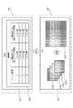
- a sixth aspect of the technique of the present disclosure is the control of the processor to move the blur correction lens to a position where the image shifts at a pitch equal to or higher than the pixel pitch of the image sensor or a pitch lower than the pixel pitch of the image sensor.
- the coordinate plane is defined by a first direction and a second direction intersecting the first direction
- the second drive mechanism is a third actuator and a fourth actuator.
- the third actuator moves the blur correction lens by applying power to the blur correction lens along the first direction
- the fourth actuator moves the blur correction lens in the second direction with respect to the blur correction lens.
- the processor selectively switches the combination of the presence / absence of power of the third actuator and the presence / absence of power of the fourth actuator to the second drive mechanism.
- the coordinate plane is defined by a first direction and a second direction intersecting the first direction
- the second drive mechanism is a third actuator and a fourth actuator.
- the third actuator moves the blur correction lens by applying power to the blur correction lens along the first direction
- the fourth actuator moves the blur correction lens in the second direction with respect to the blur correction lens. It is a lens apparatus according to any one of the first aspect to the seventh aspect, which moves a blur correction lens by applying power along the line.
- a ninth aspect according to the technique of the present disclosure is a holding member that holds a blur correction lens, a first support member that movably supports the holding member along a coordinate plane, and a first support member along the coordinate plane.
- a second support member that is movably supported, the first drive mechanism is provided between the holding member and the first support member, and the second drive mechanism is a first support member and a second support member.
- the lens device according to any one of the first to eighth aspects, which is provided between the first aspect and the eighth aspect.
- a tenth aspect according to the technique of the present disclosure is a holding member that holds a blur correction lens, a first support member that movably supports the holding member along a coordinate plane, and a first support member along the coordinate plane.
- a second support member that is movably supported, the first drive mechanism is provided between the holding member and the first support member, and the second drive mechanism is a first support member and a second support member.
- the lens device according to any one of the first to ninth aspects, which is provided between the first aspect and the ninth aspect.
- the eleventh aspect of the technique of the present disclosure is the lens device according to the tenth aspect, wherein the holding member is rotatably supported by the first support member about a shaft member extending along an optical axis. Is.
- a twelfth aspect according to the technique of the present disclosure is any one of the first to eleventh aspects, wherein the first drive mechanism has a voice coil motor and the second drive mechanism has a piezoelectric element.
- This is a lens device according to the above.
- the thirteenth aspect according to the technique of the present disclosure is the lens device according to the twelfth aspect, wherein the second drive mechanism has an elastic member arranged at a position facing the piezoelectric element.
- the coordinate plane is defined by a first direction and a second direction intersecting the first direction
- the first drive mechanism is a holding member and a first support member. It has a first actuator provided between the two and to generate power in the first direction, and a second actuator provided between the holding member and the first support member to generate power in the second direction.
- the second drive mechanism is provided between the first support member and the second support member, and is provided between the third actuator that generates power in the first direction and between the first support member and the second support member.
- the lens device according to the ninth aspect comprising a fourth actuator that generates power in the second direction.
- the coordinate plane is defined by a first direction and a second direction intersecting the first direction
- the first drive mechanism is a first support member and a second.
- a first actuator provided between the support member and generating power in the first direction
- a second actuator provided between the first support member and the second support member and generating power in the second direction.
- the second drive mechanism is provided between the holding member and the first support member, and is provided between the holding member and the first support member, and the third actuator that generates power in the first direction.
- the lens device according to the tenth aspect, comprising a fourth actuator that generates power in a second direction.
- the coordinate plane is defined by a first direction and a second direction intersecting the first direction
- the first drive mechanism is a first support member and a second.
- a first actuator provided between the support member and generating power in the first direction
- a second actuator provided between the first support member and the second support member and generating power in the second direction.
- the second drive mechanism is provided between the holding member and the first support member, and has a third actuator that generates power in the combined directions of the first direction and the second direction.
- a seventeenth aspect according to the technique of the present disclosure is any one of the first to sixteenth aspects, which is arranged closer to the subject than the image sensor and includes an optical filter that transmits near-infrared light contained in the light. It is a lens device according to one.
- An eighteenth aspect according to the technique of the present disclosure is a blur correction for correcting blur of an image obtained by forming an image of light on a processor, a memory connected to or built in the processor, an image sensor, and an image sensor.
- a lens that includes a lens and forms an image of incident light on an image sensor, and a blur correction lens along a coordinate plane that intersects the optical axis of the lens in a direction that corrects image blur.
- the first drive mechanism for moving the blur correction lens and the second drive mechanism for moving the blur correction lens by applying power to the blur correction lens along the coordinate plane in the direction in which the image is shifted. It is an image pickup apparatus provided with.
- a nineteenth aspect of the technique of the present disclosure is that the processor shifts the image to a position where the image shifts with respect to the second drive mechanism at a pitch equal to or higher than the pixel pitch of the image sensor or a pitch lower than the pixel pitch of the image sensor. It is an image pickup apparatus according to an eighteenth aspect, which controls the movement of a correction lens, causes an image sensor to take an image according to an image shift, and synthesizes images of a plurality of frames obtained by the image pickup.
- a twentieth aspect according to the technique of the present disclosure includes a blur correction lens for correcting blur of an image obtained by forming an image of light on an image sensor, and a lens for forming an image of incident light on the image sensor.
- the image shifts with the first drive mechanism that moves the blur correction lens by applying power to the blur correction lens along the coordinate plane that intersects the optical axis of the lens in the direction in which the blur of the image is corrected.
- a first drive mechanism which is a method of operating a lens device including a second drive mechanism for moving a blur correction lens by applying power to the blur correction lens along a coordinate plane in the direction of movement.
- a 21st aspect according to the technique of the present disclosure includes an image sensor and a blur correction lens that corrects blur of an image obtained by forming an image of light on the image sensor, and images incident light on the image sensor.
- a first drive mechanism that moves the blur correction lens by applying power to the blur correction lens along the coordinate plane that intersects the optical axis of the lens in the direction in which the blur of the image is corrected.
- a method of operating an image pickup device including a second drive mechanism for moving a blur correction lens by applying power to a blur correction lens along a coordinate plane in a direction in which an image is shifted.
- the first drive mechanism is controlled to move the blur correction lens in the direction in which the image blur is corrected, and the second drive mechanism is controlled to move the blur correction lens in the direction in which the image is shifted. It is a method of operating an image pickup apparatus including.
- a 22nd aspect according to the technique of the present disclosure includes a blur correction lens for correcting blur of an image obtained by forming an image of light on an image sensor, and a lens for forming an image of incident light on the image sensor.
- the image shifts with the first drive mechanism that moves the blur correction lens by applying power to the blur correction lens along the coordinate plane that intersects the optical axis of the lens in the direction in which the blur of the image is corrected.
- the first is to a computer applied to a lens device comprising a second drive mechanism for moving the blur correction lens by applying power to the blur correction lens along a coordinate plane in the direction in which it is applied.
- the drive mechanism is controlled to move the blur correction lens in the direction in which the image blur is corrected, and the second drive mechanism is controlled to move the blur correction lens in the direction in which the image is shifted. It is a program for executing processing including that.
- a 23rd aspect according to the technique of the present disclosure includes an image sensor and a blur correction lens that corrects blur of an image obtained by forming an image of light on the image sensor, and images incident light on the image sensor.
- a first drive mechanism that moves the blur correction lens by applying power to the blur correction lens along the coordinate plane that intersects the optical axis of the lens in the direction in which the blur of the image is corrected.
- a computer applied to an imaging device including a second drive mechanism that moves the blur correction lens by applying power to the blur correction lens along the coordinate plane in the direction in which the image is shifted.
- the first drive mechanism is controlled to move the blur correction lens in the direction in which the image blur is corrected
- the second drive mechanism is controlled to move the blur correction lens in the direction in which the image is shifted. It is a program for executing a process including controlling the lens.
- CPU is an abbreviation for "Central Processing Unit”.
- GPU refers to the abbreviation of "Graphics Processing Unit”.
- NVM is an abbreviation for "Non-Volatile Memory”.
- RAM is an abbreviation for "RandomAccessMemory”.
- IC refers to the abbreviation of "Integrated Circuit”.
- ASIC is an abbreviation for "Application Specific Integrated Circuit”.
- PLD is an abbreviation for "Programmable Logic Device”.
- FPGA refers to the abbreviation of "Field-Programmable Gate Array”.
- SoC is an abbreviation for "System-on-a-chip”.
- SSD is an abbreviation for "Solid State Drive”.
- HDD is an abbreviation for "Hard Disk Drive”.
- EEPROM refers to the abbreviation of "Electrically Erasable and Programmable Read Only Memory”.
- SRAM is an abbreviation for “Static Random Access Memory”.
- VCM is an abbreviation for "Voice Coil Motor”.
- I / F refers to the abbreviation of "Interface”.
- UI is an abbreviation for "User Interface”.
- USB is an abbreviation for "Universal Serial Bus”.
- CMOS is an abbreviation for "Complementary Metal Oxide Semiconductor”.
- CCD refers to the abbreviation of "Charge Coupled Device”.
- LAN is an abbreviation for "Local Area Network”.
- WAN is an abbreviation for "Wide Area Network”.
- BPF is an abbreviation for "Band Pass Filter”. Ir refers to the abbreviation of "Infrared Rays”.
- vertical means, in addition to perfect verticality, an error generally allowed in the technical field to which the technique of the present disclosure belongs, to the extent that it does not contradict the purpose of the technique of the present disclosure. Refers to the vertical in the sense including the error of.
- horizontal means, in addition to the perfect horizontal, an error generally allowed in the technical field to which the technique of the present disclosure belongs, to the extent that it does not contradict the purpose of the technique of the present disclosure. Refers to the horizontal in the sense including the error of.
- parallel means, in addition to perfect parallelism, an error generally allowed in the technical field to which the technique of the present disclosure belongs, to the extent that it does not contradict the purpose of the technique of the present disclosure. Refers to parallelism in the sense including the error of.
- orthogonality is an error generally allowed in the technical field to which the technique of the present disclosure belongs, in addition to the perfect orthogonality, and is not contrary to the purpose of the technique of the present disclosure. It refers to the orthogonality in the sense including the error of.
- match is an error generally allowed in the technical field to which the technique of the present disclosure belongs, in addition to the perfect match, to the extent that it does not contradict the purpose of the technique of the present disclosure.
- equal spacing is an error generally allowed in the technical field to which the technique of the present disclosure belongs, in addition to the perfect equal spacing, which is contrary to the purpose of the technique of the present disclosure. It refers to equal intervals in the sense that it includes errors to the extent that it does not occur.
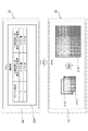
- the surveillance system S includes a surveillance camera 10 and a management device 11.
- the surveillance camera 10 is an example of the "imaging device" according to the technique of the present disclosure.
- the surveillance camera 10 is installed on a pillar or wall inside or outside the room, captures a surveillance target as a subject, and generates a moving image by capturing the image.
- the moving image includes a multi-frame image obtained by imaging.
- the surveillance camera 10 transmits the moving image obtained by imaging to the management device 11 via the communication line 12.
- the management device 11 receives the moving image transmitted by the surveillance camera 10, displays the received moving image on the display 13, or stores the received moving image in the storage device 14.
- the X-axis shown in FIG. 1 corresponds to the pitch axis of the surveillance camera 10
- the Y-axis corresponds to the yaw axis of the surveillance camera 10
- the Z-axis corresponds to the roll axis of the surveillance camera 10.
- the direction along the X-axis is referred to as the X-axis direction
- the direction along the Y-axis is referred to as the Y-axis direction
- the direction along the Z-axis is referred to as the Z-axis direction.
- the X-axis direction, the Y-axis direction, and the Z-axis direction are orthogonal to each other.
- the surveillance camera 10 includes a surveillance camera main body 20 and a lens device 70.
- the surveillance camera main body 20 is an example of the “imaging apparatus main body” according to the technique of the present disclosure.
- the surveillance camera body 20 includes a lens mount 22.
- the lens device 70 is separate from the surveillance camera main body 20, and is detachably attached to the lens mount 22.
- the lens device 70 is provided on the surveillance camera body 20 by being attached to the lens mount 22.
- the surveillance camera body 20 includes an image sensor 24.
- the image sensor 24 is, for example, a CMOS image sensor, which photoelectrically converts the received light and outputs an electric signal corresponding to the received light.
- the CMOS image sensor is merely an example, and the image sensor 24 may be an image sensor whose operation method is different from that of a CMOS image sensor such as a CCD image sensor.
- the image sensor 24 has a light receiving surface 24A.
- the image pickup region light incident on the lens device 70 is imaged on the light receiving surface 24A by the lens device 70.
- An image is obtained by forming an image of the light in the imaging region on the light receiving surface 24A.
- a plurality of photodiodes are arranged in a matrix on the light receiving surface 24A. Each photodiode receives light in the imaging region.
- the image sensor 24 captures an imaging region by receiving light in the imaging region.
- the plurality of photodiodes include a silicon photodiode that is sensitive to visible light and an indium gallium arsenide photodiode that is sensitive to near-infrared light.
- the image sensor 24 takes an image of each of the visible light and the near-infrared light included in the image pickup region light imaged on the light receiving surface 24A.
- the lens device 70 has an optical axis OA.
- the optical axis OA is an axis that passes through the center of the light receiving surface 24A and is perpendicular to the light receiving surface 24A.
- the optical axis OA is parallel to the Z axis.
- the lens device 70 includes an objective lens 72, a zoom lens 74, a blur correction lens 76, an aperture 78, a filter unit 80, and a master lens 82.
- An objective lens 72, a zoom lens 74, a blur correction lens 76, an aperture 78, a filter unit 80, and a master lens 82 are arranged in order from the subject side to the image side along the optical axis OA.
- the optical axis OA is an axis that passes through the center of each lens of the objective lens 72, the zoom lens 74, the blur correction lens 76, and the master lens 82.
- the optical axis OA is also the optical axis of each lens of the objective lens 72, the zoom lens 74, the blur correction lens 76, and the master lens 82, and is an example of the "optical axis of the lens" according to the technique of the present disclosure.
- the image pickup region light is incident on the objective lens 72.
- the objective lens 72 guides the incident image pickup region light to the zoom lens 74.
- the zoom lens 74 comprises a lens group having a plurality of lenses that can move along the optical axis OA, and is used for zooming in the imaging region.
- the blur correction lens 76 is a lens for correcting blur of an image obtained by forming an image pickup region light on the image sensor 24 as described later, and the image is along the light receiving surface 24A of the image sensor 24. It is a lens for shifting.
- the aperture 78 has an opening 78A.
- the imaging region light guided by the zoom lens 74 passes through the aperture 78A.
- the diaphragm 78 is a movable diaphragm whose diameter of the opening 78A can be changed. That is, the amount of light in the imaging region is changed by the aperture 78.
- the filter unit 80 is arranged closer to the subject than the image sensor 24. As an example, the filter unit 80 is arranged between the aperture 78 and the master lens 82. The image pickup region light transmitted through the diaphragm 78 is incident on the filter unit 80. As will be described in detail later, the filter unit 80 has a plurality of optical filters having translucency, and is included in the image pickup region light by switching the optical filter that transmits light among the plurality of optical filters. It selectively transmits light in a plurality of wavelength bands (for example, visible light in different wavelength bands and near-infrared light).
- a plurality of optical filters having translucency
- the image pickup region light transmitted through the filter unit 80 is incident on the master lens 82, and the image pickup region light incident on the master lens 82 is imaged on the light receiving surface 24A.
- the image pickup region light incident on the lens device 70 is guided to the image sensor 24 by the plurality of lenses provided in the lens device 70, and is imaged on the light receiving surface 24A of the image sensor 24.
- the blur correction lens 76 included in the plurality of lenses provided in the lens device 70 is an example of the “blurring correction lens” according to the technique of the present disclosure.
- a plurality of lenses including an objective lens 72, a zoom lens 74, a blur correction lens 76, an aperture 78, a filter unit 80, and a master lens 82 are examples of the “lens” according to the technique of the present disclosure.
- the order of the objective lens 72, the zoom lens 74, the blur correction lens 76, the aperture 78, the filter unit 80, and the master lens 82 may be other than the above.
- each of the objective lens 72, the zoom lens 74, the blur correction lens 76, and the master lens 82 may be a single lens or a lens group having a plurality of lenses.
- the lens device 70 may include an objective lens 72, a zoom lens 74, a blur correction lens 76, and a master lens 82, as well as other lenses.
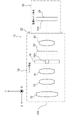
- the filter unit 80 includes a disk 84.
- the disk 84 is provided with a first BPF88A, a second BPF88B, a third BPF88C, and a fourth BPF88D as a plurality of optical filters at equal intervals along the circumferential direction.
- the first BPF88A, the second BPF88B, the third BPF88C, and the fourth BPF88D are referred to as an optical filter unless it is necessary to separately explain them.
- the first BPF88A, the second BPF88B, the third BPF88C, and the fourth BPF88D are referred to as BPF88, unless it is necessary to explain them separately.
- the filter unit 80 selectively inserts and removes a plurality of optical filters in the lens device 70 with respect to the optical path of the imaging region light (hereinafter, simply referred to as “optical path”) in the lens device 70 by a turret method.
- optical path the optical path of the imaging region light
- the disk 84 rotates along the circumferential direction (for example, the direction of the arc dashed arrow shown in FIG. 3)
- the first BPF88A, the second BPF88B, the third BPF88C, and the fourth BPF88D become an optical path (in FIG. 3).
- it is selectively inserted and removed with respect to the optical axis OA).
- the first BPF88A, the second BPF88B, the third BPF88C, and the fourth BPF88D transmit light in different wavelength bands.
- the optical axis OA penetrates the center of the optical path, and the center of the optical filter inserted into the optical path coincides with the center of the light receiving surface 24A.
- the optical axis OA penetrates the center of the first BPF88A, and the center of the first BPF88A coincides with the center of the light receiving surface 24A.
- the first BPF88A, the second BPF88B, and the third BPF88C are optical filters that transmit visible light
- the fourth BPF88D is an optical filter that transmits near infrared light.
- the first BPF88A is an optical filter that transmits only light in the blue wavelength band, that is, visible light in the band of, for example, 400 nm to 490 nm.
- the second BPF88B is an optical filter that transmits only light in the green wavelength band, that is, visible light in the band of, for example, 490 nm to 550 nm.
- the third BPF88C is an optical filter that transmits only light in the red wavelength band, that is, visible light in the band of, for example, 640 nm to 770 nm.
- the fourth BPF88D is, for example, an optical filter that transmits only near-infrared light in the band of 1450 nm to 1650 nm.
- each band mentioned here includes an error that is generally allowed in the technical field to which the technique of the present disclosure belongs and is within a range that does not deviate from the purpose of the technique of the present disclosure.
- each wavelength band mentioned here is merely an example, and may be different wavelength bands.
- the image sensor 24 has a light receiving unit 26 and a color filter unit 28.
- the light receiving unit 26 has a plurality of first light receiving elements 30 and a plurality of second light receiving elements 32.
- An example of the first light receiving element 30 is an indium gallium arsenic photodiode.
- An example of the second light receiving element 32 is a silicon photodiode.
- a color filter unit 28 is arranged on the plurality of first light receiving elements 30 and the plurality of second light receiving elements 32.
- the color filter unit 28 has an Ir filter, an R filter, a G filter, and a B filter.
- the Ir filter is a filter that transmits light of a near infrared (Ir) component.
- the R filter is a filter that transmits light of the red (R) component.
- the G filter is a filter that transmits light of a green (G) component.
- the B filter is a filter that transmits light of the blue (B) component.
- the first light receiving element 30 is a light receiving element having sensitivity to the light of the Ir component.
- the second light receiving element 32 is roughly classified into a light receiving element 32R having sensitivity to light of R component, a light receiving element 32G having sensitivity to light of G component, and a light receiving element 32B having sensitivity to light of B component. ..
- An Ir filter is arranged on the first light receiving element 30.
- An R filter is arranged on the light receiving element 32R.
- a G filter is arranged on the light receiving element 32G.
- a B filter is arranged on the light receiving element 32B.
- a filter for blocking near-infrared light is further arranged in each of the light receiving elements 32R, 36G and 36B.
- the plurality of second light receiving elements 32 receive visible light transmitted through any one of the first BPF88A, the second BPF88B, and the third BPF88C, and the visible light is based on the received visible light.
- the image 60 is generated and output, and the plurality of first light receiving elements 30 receive the near-infrared light transmitted through the fourth BPF88D, and generate the near-infrared light image 62 based on the received near-infrared light. Output.
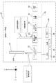
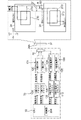
- the surveillance camera main body 20 includes a controller 40 and a UI system device 50.
- the controller 40 controls the operation of the surveillance camera body 20.
- the controller 40 includes a CPU 42, an NVM 44, and a RAM 46.
- the CPU 42, NVM 44, and RAM 46 are connected to the bus 48.
- NVM44 stores various parameters and various programs.
- An example of the NVM44 is an EEPROM (for example, a flash type EEPROM).
- EEPROM is just an example of NVM44.
- the NVM 44 may be any non-volatile storage device such as SSD and / or HDD.
- the RAM 46 temporarily stores various information and is used as a work memory.
- An example of the RAM 46 is a DRAM.
- DRAM is just an example of RAM 46.
- the RAM 46 may be a SRAM and may be any volatile storage device.
- the CPU 42 reads a necessary program from the NVM 44 and executes the read program on the RAM 46.
- the CPU 42 executes various processes according to a program executed on the RAM 46.
- the UI device 50 is also connected to the bus 48. Under the control of the CPU 42, the UI system device 50 receives an instruction given by the user and presents various information obtained by being processed by the surveillance camera 10 to the user.
- the surveillance camera main body 20 includes an image sensor driver 52, a signal processing device 54, a blur amount detection sensor 56, and a communication I / F 58.
- the image sensor driver 52, the signal processing device 54, the blur amount detection sensor 56, and the communication I / F 58 are connected to the bus 48.
- the image sensor 24 is located on the optical axis OA after the master lens 82, that is, on the image side of the master lens 82.
- the image sensor 24 is visible imaged on the light receiving surface 24A by the master lens 82.
- the visible light image 60 shown in FIG. 4 is generated, and the generated visible light image 60 is output to the subsequent stage.
- the visible light image 60 is an image showing an image pickup region by visible light.
- the image sensor 24 images an image pickup region based on the near-infrared light imaged on the light receiving surface 24A by the master lens 82.
- the near-infrared light image 62 shown in FIG. 4 is generated, and the generated near-infrared light image 62 is output to the subsequent stage.
- the near-infrared light image 62 is an image showing an image pickup region by near-infrared light.
- captured images without reference numerals.
- an image sensor driver 52 and a signal processing device 54 are connected to the image sensor 24.
- the image sensor driver 52 outputs a timing control signal to the image sensor 24 under the control of the CPU 42.
- the timing control signal is a signal that controls imaging by the image sensor 24.
- the frame rate of the image taken by the image sensor 24 is defined by the timing control signal.
- the timing control signal includes a vertical synchronization signal and a horizontal synchronization signal.
- the vertical synchronization signal is a signal that defines the timing at which transmission of an analog image for one frame is started.
- the horizontal synchronization signal is a signal that defines the timing at which the output of an analog image for one horizontal line is started.
- the image sensor 24 starts outputting the captured image to the signal processing device 54 in frame units according to the vertical synchronization signal input from the image sensor driver 52. Further, the image sensor 24 starts outputting the captured image to the signal processing device 54 in units of horizontal lines according to the horizontal synchronization signal input from the image sensor driver 52.
- the signal processing device 54 Under the control of the CPU 42, the signal processing device 54 performs signal processing such as demosaic processing, noise removal processing, gradation correction processing, and color correction processing on the captured image input from the image sensor 24.
- the captured image after signal processing is output to the CPU 42 by the signal processing device 54.
- the CPU 42 stores the captured image input from the signal processing device 54 in a predetermined storage area (for example, NVM 44 and / or RAM 46, etc.).
- the blur amount detection sensor 56 detects, for example, the amount of blur of the surveillance camera 10 shown in FIG. 2 (hereinafter, also simply referred to as “shake amount”).
- the blurring of the surveillance camera 10 refers to a phenomenon in which the positional relationship between the optical axis OA and the light receiving surface 24A fluctuates in the surveillance camera 10.
- the image is blurred.
- an image obtained by being imaged by an image sensor and / or an optical image obtained by being imaged on the light receiving surface 24A hereinafter, simply "image” or "subject”). Also called “image”).
- the "image blur” is a phenomenon in which the subject image deviates from the reference position due to the tilt of the optical axis OA due to the vibration phenomenon, that is, the movement of the optical axis OA relative to the subject.
- the vibration phenomenon is a lens device 70 in which vibration is generated from the outside of the surveillance camera 10 (for example, a hand, a wind, and / or a vehicle, etc.) and / or the inside of the surveillance camera 10 (for example, a motor mounted on the surveillance camera 10).
- the optical axis OA is tilted means, for example, with respect to the reference axis (for example, the optical axis OA before the vibration phenomenon occurs (that is, the optical axis OA when the surveillance camera 10 is stationary)). It means that the optical axis OA is tilted.
- the "reference position” refers to, for example, the position of the subject image obtained in a state where vibration is not applied to the lens device 70 (for example, the position of the subject image in the light receiving surface 24A).
- the shake amount detection sensor 56 shown in FIG. 5 is, for example, a gyro sensor.
- the gyro sensor detects the amount of rotational shake around each of the X-axis, Y-axis, and Z-axis.
- the shake amount detection sensor 56 converts the amount of rotational shake around the X-axis and the amount of rotational shake around the Y-axis detected by the gyro sensor into the amount of shake in a two-dimensional plane parallel to the X-axis and the Y-axis. By converting, the amount of blurring of the surveillance camera 10 is detected.
- the meaning of parallelism in the present embodiment includes not only the meaning of perfect parallelism but also the meaning of substantially parallelism including errors allowed in design and manufacturing.
- the gyro sensor is mentioned as an example of the shake amount detection sensor 56, but this is only an example, and the shake amount detection sensor 56 may be an acceleration sensor.
- the accelerometer detects the amount of blurring in a two-dimensional plane parallel to the X-axis and the Y-axis.
- the blur amount detection sensor 56 outputs the detected blur amount to the CPU 42.
- the amount of blur is detected by a physical sensor called the blur amount detection sensor 56
- the technique of the present disclosure is not limited to this.
- the motion vector obtained by comparing the captured images stored in the NVM 44 or the RAM 46 in chronological order may be used as the amount of blur.
- the amount of blur finally used may be derived based on the amount of blur detected by the physical sensor and the motion vector obtained by the image processing.
- the communication I / F 58 is, for example, a network interface, and controls transmission of various information to and from the management device 11 via the network.
- An example of a network is a WAN such as the Internet or a public communication network.
- the communication I / F 58 controls communication between the surveillance camera 10 shown in FIG. 1 and the management device 11.
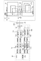
- the lens device 70 includes a controller 90.
- the controller 90 controls the operation of the lens device 70.
- the controller 90 includes a CPU 92, an NVM 94, and a RAM 96.
- the controller 90 is an example of a "computer applied to a lens device"
- the CPU 92 is an example of a “processor” according to the technique of the present disclosure
- the RAM 96 is an example of the "memory” according to the technique of the present disclosure. This is just one example.
- the CPU 92, NVM 94, and RAM 96 are connected to the bus 98.
- the lens device 70 when the lens device 70 is attached to the lens mount 22 of the surveillance camera body 20, a connector (not shown) provided on the surveillance camera body 20 and a connector provided on the lens device 70 are provided. (Not shown) is connected. Then, the CPU 42 of the surveillance camera body 20 shown in FIG. 5 and the CPU 92 of the lens device 70 shown in FIG. 6 are communicably connected via a connection path including the connector of the surveillance camera body 20 and the connector of the lens device 70. Will be done. The CPU 92 of the lens device 70 controls the operation of the lens device 70 according to an instruction given from the CPU 42 of the surveillance camera main body 20.
- NVM94 stores various parameters and various programs.
- An example of the NVM94 is an EEPROM (for example, a flash type EEPROM).
- EEPROM is just an example of NVM94.
- the NVM94 may be any non-volatile storage device such as SSD and / or HDD.
- the RAM 96 temporarily stores various information and is used as a work memory.
- An example of RAM 96 is DRAM.
- DRAM is just an example of RAM 96.
- the RAM 96 may be a SRAM, and may be any volatile storage device.
- the CPU 92 reads a necessary program from the NVM 94 and executes the read program on the RAM 96.
- the CPU 92 executes various processes according to a program executed on the RAM 96.
- the "various programs" referred to here also include a blur correction / shift processing program 100 (see FIG. 9) described later.
- the triaxial directions orthogonal to each other are defined in the X-axis direction, the Y-axis direction, and the Z-axis direction.
- the X-axis direction, the Y-axis direction, and Z of the lens device 70 may deviate from the X-axis direction, the Y-axis direction, and the Z-axis direction of the surveillance camera 10, respectively.
- the X-axis direction, the Y-axis direction, and Z of the lens device 70 It is assumed that the axial direction coincides with the X-axis direction, the Y-axis direction, and the Z-axis direction of the surveillance camera 10, respectively.
- the X-axis direction and the Y-axis direction are directions orthogonal to the optical axis OA of the lens device 70, respectively, and the Z-axis direction is a direction parallel to the optical axis OA.
- the lens device 70 includes a first motor driver 102, an X-axis VCM driver 104, a Y-axis VCM driver 106, an X-axis piezoelectric element driver 108, a Y-axis piezoelectric element driver 110, and a second motor driver. It includes 112, a third motor driver 114, and a fourth motor driver 116. Further, the lens device 70 includes a first motor 118, an X-axis VCM 120, a Y-axis VCM 122, an X-axis piezoelectric element 124, a Y-axis piezoelectric element 126, a second motor 128, a third motor 130, and a fourth motor 132. Further, the lens device 70 includes a first position sensor 134, an X-axis position sensor 136, a Y-axis position sensor 138, a second position sensor 140, a third position sensor 142, and a fourth position sensor 144.
- the first position sensor 134, the X-axis position sensor 136, the Y-axis position sensor 138, the second position sensor 140, the third position sensor 142, and the fourth position sensor 144 are connected to the bus 98.
- each of the first position sensor 134, the X-axis position sensor 136, the Y-axis position sensor 138, the second position sensor 140, the third position sensor 142, and the fourth position sensor 144 is a potentiometer.
- the first position sensor 134 detects the position of the zoom lens 74 in the Z-axis direction.
- the X-axis position sensor 136 detects the position of the blur correction lens 76 in the X-axis direction.
- the Y-axis position sensor 138 detects the position of the blur correction lens 76 in the Y-axis direction.
- the second position sensor 140 detects the aperture of the opening 78A formed in the aperture 78.
- the third position sensor 142 detects the rotational position of the filter unit 80 with respect to the optical axis OA.
- the fourth position sensor 144 detects the position of the master lens 82 in the Z-axis direction.
- the detection result by the first position sensor 134 is output to the CPU 92 by the first position sensor 134.
- the detection result by the X-axis position sensor 136 is output to the CPU 92 by the X-axis position sensor 136.
- the detection result by the Y-axis position sensor 138 is output to the CPU 92 by the Y-axis position sensor 138.
- the detection result by the second position sensor 140 is output to the CPU 92 by the second position sensor 140.
- the detection result by the third position sensor 142 is output to the CPU 92 by the third position sensor 142.
- the detection result by the 4th position sensor 144 is output to the CPU 92 by the 4th position sensor 144.
- the zoom lens 74 is attached to the first slide mechanism (not shown).
- the first slide mechanism is mechanically connected to the drive shaft of the first motor 118, and receives the power of the first motor 118 to move the zoom lens 74 along the Z-axis direction.
- the first motor driver 102 is connected to the first motor 118 and controls the first motor 118 according to an instruction from the CPU 92.
- the CPU 92 controls the position of the zoom lens 74 in the Z-axis direction by controlling the first motor 118 via the first motor driver 102 based on the detection result by the first position sensor 134.
- the blur correction lens 76 is attached to a blur correction / shift drive mechanism 150 (see FIGS. 7 and 8) whose mechanical structure will be described in detail later.
- the blur correction / shift drive mechanism 150 includes an X-axis VCM 120 and a Y-axis VCM 122.
- the X-axis VCM 120 moves the blur correction lens 76 along the X-axis direction by applying power to the blur correction lens 76 along the X-axis direction.
- the Y-axis VCM 122 moves the blur correction lens 76 along the Y-axis direction by applying power to the blur correction lens 76 along the Y-axis direction.
- the X-axis VCM driver 104 is connected to the X-axis VCM 120 and controls the X-axis VCM 120 according to an instruction from the CPU 92.
- the CPU 92 is X via the X-axis VCM driver 104 based on the blur amount detection result by the blur amount detection sensor 56 output from the CPU 42 shown in FIG. 5 and the detection result by the X-axis position sensor 136 shown in FIG.
- the Y-axis VCM driver 106 is connected to the Y-axis VCM 122 and controls the Y-axis VCM 122 according to an instruction from the CPU 92.
- the CPU 92 is Y via the Y-axis VCM driver 106 based on the blur amount detection result by the blur amount detection sensor 56 output from the CPU 42 shown in FIG. 5 and the detection result by the Y-axis position sensor 138 shown in FIG.
- the axis VCM 122 By controlling the axis VCM 122, the position of the blur correction lens 76 in the Y-axis direction is controlled.
- the blur correction / shift drive mechanism 150 includes an X-axis piezoelectric element 124 and a Y-axis piezoelectric element 126.
- the X-axis piezoelectric element 124 moves the blur correction lens 76 along the X-axis direction by applying power to the blur correction lens 76 along the X-axis direction.
- the Y-axis piezoelectric element 126 moves the blur correction lens 76 along the Y-axis direction by applying power to the blur correction lens 76 along the Y-axis direction.
- the X-axis piezoelectric element driver 108 is connected to the X-axis piezoelectric element 124, and controls the X-axis piezoelectric element 124 according to an instruction from the CPU 92.
- the CPU 92 controls the X-axis piezoelectric element 124 via the X-axis piezoelectric element driver 108 based on the image shift command output from the CPU 42 shown in FIG. 5 and the detection result by the X-axis position sensor 136 shown in FIG. By doing so, the position of the blur correction lens 76 in the X-axis direction is controlled.
- the Y-axis piezoelectric element driver 110 is connected to the Y-axis piezoelectric element 126, and controls the Y-axis piezoelectric element 126 according to an instruction from the CPU 92.
- the CPU 92 controls the Y-axis piezoelectric element 126 via the Y-axis piezoelectric element driver 110 based on the image shift command output from the CPU 42 shown in FIG. 5 and the detection result by the Y-axis position sensor 138 shown in FIG. By doing so, the position of the blur correction lens 76 in the Y-axis direction is controlled.
- the diaphragm 78 has a plurality of blades (not shown) capable of opening and closing the opening 78A.
- the plurality of blades are mechanically connected to the drive shaft of the second motor 128, and open and close the opening 78A by receiving the power of the second motor 128.
- the second motor driver 112 is connected to the second motor 128 and controls the second motor 128 according to the instruction from the CPU 92.
- the CPU 92 controls the second motor 128 via the second motor driver 112 shown in FIG. 6 based on the detection result by the second position sensor 140 and the light receiving amount on the light receiving surface 24A shown in FIG. , The opening degree of the opening 78A is adjusted.
- the filter unit 80 is attached to a rotation mechanism (not shown).
- the rotation mechanism is mechanically connected to the drive shaft of the third motor 130, and receives the power of the third motor 130 to rotate the disk 84 (see FIG. 3) in the circumferential direction, thereby causing a plurality of rotation mechanisms. Insert and remove the optical filter into the optical path.
- the third motor driver 114 is connected to the third motor 130 and controls the third motor 130 according to the instruction from the CPU 92.
- the CPU 92 controls the rotation position of the filter unit 80 with respect to the optical axis OA by controlling the third motor 130 via the third motor driver 114 based on the detection result by the third position sensor 142.
- the master lens 82 is attached to a second slide mechanism (not shown).
- the second slide mechanism is mechanically connected to the drive shaft of the fourth motor 132, and receives the power of the fourth motor 132 to move the master lens 82 along the Z-axis direction.
- the fourth motor driver 116 is connected to the fourth motor 132, and controls the fourth motor 132 according to an instruction from the CPU 92.
- the CPU 92 controls the position of the master lens 82 in the Z-axis direction by controlling the fourth motor 132 via the fourth motor driver 116 based on the detection result by the fourth position sensor 144.
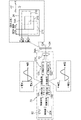
- the shake correction / shift drive mechanism 150 includes a holding member 152, a first support member 154, a second support member 156, an X-axis VCM120, a Y-axis VCM122, and an X-axis piezoelectric element 124. , Y-axis piezoelectric element 126, X-axis leaf spring 158, and Y-axis leaf spring 160.
- the + X-axis direction indicates a direction toward the first side in the X-axis direction
- the -X-axis direction indicates a direction toward the second side opposite to the first side in the X-axis direction.
- the + Y-axis direction indicates a direction toward the first side in the Y-axis direction
- the ⁇ Y-axis direction indicates a direction toward the second side opposite to the first side in the Y-axis direction.
- the + Z-axis direction indicates a direction toward the first side in the Z-axis direction
- the ⁇ Z-axis direction indicates a direction toward the second side opposite to the first side in the Z-axis direction.
- the + X-axis direction and the -X-axis direction are collectively referred to as the X-axis direction.
- the + Y-axis direction and the ⁇ Y-axis direction are not distinguished, the + Y-axis direction and the ⁇ Y-axis direction are collectively referred to as the Y-axis direction.
- the + Z axis direction and the ⁇ Z axis direction are collectively referred to as the Z axis direction.
- the Z-axis direction is parallel to the optical axis OA of the lens device 70.
- the + Z-axis direction corresponds to the subject side
- the ⁇ Z-axis direction corresponds to the image side.
- the XY coordinate planes used in the following description are defined in the X-axis direction and the Y-axis direction.
- the XY coordinate plane is an example of the "coordinate plane intersecting the optical axis of the lens" according to the technique of the present disclosure
- the X-axis direction is an example of the "first direction” according to the technique of the present disclosure
- the Y-axis direction is an example of the "second direction intersecting the first direction” according to the technique of the present disclosure.
- the holding member 152 is roughly formed in a plate shape.
- the holding member 152 is arranged with the Z-axis direction as the plate thickness direction.
- the holding member 152 is formed with a hole 162 penetrating in the Z-axis direction.
- the hole 162 has a circular cross-sectional shape when viewed from the axial direction.
- a blur correction lens 76 is arranged inside the hole 162.
- An annular fixing member 164 is provided on the outer peripheral portion of the blur correction lens 76, and the outer peripheral portion of the blur correction lens 76 is fixed to the inner peripheral surface of the hole 162 via the fixing member 164 or the like.
- the blur correction lens 76 is held by the holding member 152 by fixing the outer peripheral portion to the inner peripheral surface of the hole 162 via the fixing member 164 or the like.
- the shake correction lens 76 is on the optical axis OA. The center is located.
- the first support member 154 is roughly formed in a plate shape.
- the first support member 154 is arranged with the Z-axis direction as the plate thickness direction.
- the first support member 154 is arranged so as to face the holding member 152 in the Z-axis direction.
- the first support member 154 is formed with a hole 166 penetrating in the Z-axis direction.
- the hole 166 has a circular cross-sectional shape when viewed from the axial direction.
- the hole 166 is formed in a size having a diameter equal to or larger than the diameter of the blur correction lens 76.
- the first support member 154 is arranged in the ⁇ Z axis direction with respect to the holding member 152.
- the first support member 154 may be arranged in the + Z axis direction with respect to the holding member 152.
- a sliding member such as a ball between the holding member 152 and the first support member 154, the holding member 152 is placed on the XY coordinate plane by the first support member 154. It is movably supported along.
- the center of the hole 166 is on the optical axis OA. To position.
- the second support member 156 is fixed to the housing 70A of the lens device 70.
- the housing 70A of the lens device 70 includes the objective lens 72, the zoom lens 74, the aperture 78, the filter unit 80, and the master lens 82 (see FIG. 2). ) And the like, and the second support member 156 is fixed to the housing 70A of the lens device 70.
- the second support member 156 is formed in a substantially disk shape having a plate-shaped portion 168 and an annular portion 170 formed along the outer peripheral portion of the plate-shaped portion 168.
- the annular portion 170 extends in the + Z axis direction from the outer peripheral portion of the plate-shaped portion 168.
- the second support member 156 is arranged so that the plate thickness direction of the plate-shaped portion 168 coincides with the Z-axis direction.
- a first support member 154 is arranged inside the annular portion 170 formed on the second support member 156, and the first support member 154 is arranged so as to face the plate-shaped portion 168 in the Z-axis direction.
- a hole 172 penetrating in the Z-axis direction is formed in the plate-shaped portion 168.
- the hole 172 has a circular cross-sectional shape when viewed from the axial direction.
- the hole 172 is formed in a size having a diameter equal to or larger than the diameter of the blur correction lens 76.
- the center of the hole 172 is located on the optical axis OA.
- a sliding member such as a ball is arranged between the first support member 154 and the plate-shaped portion 168, so that the first support member 154 is XY by the second support member 156. It is movably supported along the coordinate plane.
- the X-axis VCM120 and the Y-axis VCM122 form a blur correction drive mechanism 174.
- the X-axis VCM120 is an example of the "voice coil motor” and the “first actuator” according to the technique of the present disclosure
- the Y-axis VCM122 is the “voice coil motor” and the “second actuator” according to the technique of the present disclosure.
- the blur correction drive mechanism 174 is an example of the "first drive mechanism” according to the technique of the present disclosure.
- the shake correction drive mechanism 174 is provided between the holding member 152 and the first support member 154.
- the blur correction drive mechanism 174 applies power to the blur correction lens 76 along the XY coordinate plane in the direction in which the blur of the image is corrected, thereby moving the blur correction lens 76 to the XY coordinate plane. Move along. That is, the X-axis VCM 120 causes the blur correction lens 76 in the X-axis direction by applying power to the blur correction lens 76 along the X-axis direction in the direction in which the blur in the X-axis direction of the image is corrected.
- the Y-axis VCM 122 applies power to the blur correction lens 76 along the Y-axis direction in the direction in which the blur in the Y-axis direction of the image is corrected, thereby causing the blur correction lens 76 to Y. Move along the axial direction.
- the X-axis VCM 120 is arranged in the + X-axis direction with respect to the blur correction lens 76.
- the X-axis VCM 120 may be arranged in the ⁇ X-axis direction with respect to the blur correction lens 76.
- the X-axis VCM 120 is provided between the holding member 152 and the first support member 154 in the Z-axis direction.
- the X-axis VCM 120 is a flat coil type voice coil motor, which has a coil 176 and a pair of magnets 178 and 180.
- the coil 176 is fixed to the holding member 152, and the pair of magnets 178 and 180 are fixed to the first support member 154.
- the coil 176 may be fixed to the first support member 154, and the pair of magnets 178 and 180 may be fixed to the holding member 152.
- the coil 176 is arranged with the Z-axis direction as the axial direction, and the pair of magnets 178 and 180 are arranged side by side in the X-axis direction.
- the north pole of the magnet 178 faces the coil 176, and the south pole of the magnet 180 faces the coil 176.
- the X-axis VCM120 generates power in the X-axis direction.
- the direction of the current flowing through the coil 176 is switched by the X-axis VCM driver 104 (see FIG. 6). By switching the direction of the current flowing through the coil 176, the direction of the force received by the coil 176 from the pair of magnets 178 and 180 is switched.
- the coil 176 receives a force from the pair of magnets 178 and 180 in the + X-axis direction
- power is applied to the holding member 152 and the blur correction lens 76 in the + X-axis direction, and the holding member 152 and the blur correction lens 76 are subjected to power. Move in the + X-axis direction.
- the coil 176 When the coil 176 receives a force in the ⁇ X axis direction from the pair of magnets 178 and 180, power is applied to the holding member 152 and the blur correction lens 76 in the ⁇ X axis direction, and the holding member 152 and the blur correction lens are applied. 76 moves in the ⁇ X axis direction.
- the blur correction lens 76 moves in the X-axis direction, thereby correcting the blur in the X-axis direction of the image.
- the Y-axis VCM 122 is arranged in the ⁇ Y-axis direction with respect to the blur correction lens 76.
- the Y-axis VCM 122 may be arranged in the + Y-axis direction with respect to the blur correction lens 76.
- the Y-axis VCM 122 is provided between the holding member 152 and the first support member 154 in the Z-axis direction.
- the Y-axis VCM 122 is, for example, a flat coil type voice coil motor, which has a coil 182 and a pair of magnets 184 and 186.
- the coil 182 is fixed to the holding member 152, and the pair of magnets 184 and 186 are fixed to the first support member 154.
- the coil 182 may be fixed to the first support member 154, and the pair of magnets 184 and 186 may be fixed to the holding member 152.
- the coil 182 is arranged with the Z-axis direction as the axial direction, and the pair of magnets 184 and 186 are arranged side by side in the Y-axis direction.
- the north pole of the magnet 184 faces the coil 182, and the south pole of the magnet 186 faces the coil 182.
- the Y-axis VCM 122 generates power in the Y-axis direction.
- the direction of the current flowing through the coil 182 is switched by the Y-axis VCM driver 106 (see FIG. 6). By switching the direction of the current flowing through the coil 182, the direction of the force received by the coil 182 from the pair of magnets 184 and 186 is switched.
- the coil 182 receives a force in the + Y-axis direction from the pair of magnets 184 and 186
- power is applied to the holding member 152 and the blur correction lens 76 in the + Y-axis direction, and the holding member 152 and the blur correction lens 76 are subjected to power. Move in the + Y-axis direction.
- the X-axis VCM 120 is a flat coil type voice coil motor in which a coil 176 and a pair of magnets 178 and 180 face each other in the axial direction of the coil 176, whereas the X-axis VCM 120 is in the radial direction of the coil 176.
- a square coil type voice coil motor in which a coil 176 is arranged between a pair of magnets 178 and 180 facing each other may be used.
- the Y-axis VCM 122 is a flat coil type voice coil motor in which a coil 182 and a pair of magnets 184 and 186 face each other in the axial direction of the coil 182, whereas the Y-axis VCM 122 is a radial direction of the coil 182.
- a square coil type voice coil motor in which a coil 182 is arranged between a pair of magnets 184 and 186 facing each other may be used.
- the X-axis piezoelectric element 124, the Y-axis piezoelectric element 126, the X-axis leaf spring 158, and the Y-axis leaf spring 160 form a shift drive mechanism 188.
- the X-axis piezoelectric element 124 is an example of the "actuator” and the “third actuator” according to the technique of the present disclosure
- the Y-axis piezoelectric element 126 is the "actuator” and the "fourth actuator” according to the technique of the present disclosure. This is just an example.
- the X-axis leaf spring 158 is an example of the "first elastic member” according to the technique of the present disclosure
- the Y-axis leaf spring 160 is an example of the "second elastic member” according to the technique of the present disclosure, and is a shift drive.
- the mechanism 188 is an example of the "second drive mechanism” according to the technique of the present disclosure.
- the shift drive mechanism 188 is provided between the first support member 154 and the second support member 156.
- the shift drive mechanism 188 moves the blur correction lens 76 along the XY coordinate plane by applying power to the blur correction lens 76 along the XY coordinate plane in the direction in which the image is shifted.
- the X-axis piezoelectric element 124 applies power to the blur correction lens 76 along the X-axis direction in the direction of shifting the image along the X-axis direction, thereby causing the blur correction lens 76 to move in the X-axis direction.
- the Y-axis piezoelectric element 126 is moved along the Y-axis direction, and the Y-axis piezoelectric element 126 applies power to the blur correction lens 76 along the Y-axis direction in the direction of shifting the image along the Y-axis direction, thereby causing the blur correction lens 76. Is moved along the Y-axis direction.
- the X-axis piezoelectric element 124 is arranged in the ⁇ X-axis direction with respect to the first support member 154.
- the X-axis piezoelectric element 124 is provided between the first support member 154 and the second support member 156 in the X-axis direction.
- an actuator such as a DC motor that generates the same power as the piezoelectric element may be used.
- the X-axis leaf spring 158 is arranged at a position facing the X-axis piezoelectric element 124. That is, the X-axis leaf spring 158 is arranged in the + X-axis direction with respect to the first support member 154.
- the X-axis piezoelectric element 124 is provided between the first support member 154 and the second support member 156 in the X-axis direction.
- the X-axis leaf spring 158 is, for example, a U-shaped or V-shaped leaf spring.
- the X-axis piezoelectric element 124 may be arranged in the + X-axis direction with respect to the first support member 154, and the X-axis leaf spring 158 may be arranged in the ⁇ X-axis direction with respect to the first support member 154. Further, the X-axis leaf spring 158 may be a leaf spring having a shape other than the U-shape or the V-shape. Further, instead of the X-axis leaf spring 158, an elastic member having elasticity such as a coil spring, a torsion spring, rubber, or a sponge may be used.
- the X-axis piezoelectric element 124 generates power in the X-axis direction.
- the X-axis piezoelectric element 124 is arranged in a direction in which power is generated in the + X-axis direction. Whether or not power is supplied to the X-axis piezoelectric element 124 is switched by the X-axis piezoelectric element driver 108 (see FIG. 6).
- the X-axis piezoelectric element driver 108 see FIG. 6
- the X-axis piezoelectric element driver 108 see FIG. 6
- the X-axis piezoelectric element 124 When the X-axis piezoelectric element 124 is activated, power is applied to the holding member 152 and the blur correction lens 76 via the second support member 156 by the X-axis piezoelectric element 124 in the + X-axis direction, and the holding member 152 and the blur correction lens are applied. 76 and the second support member 156 move in the + X-axis direction against the elastic force of the X-axis leaf spring 158. By applying power by the X-axis piezoelectric element 124 in this way, the blur correction lens 76 moves, and the image is shifted in the + X-axis direction.
- the elastic force in the ⁇ X-axis direction due to the X-axis leaf spring 158 is applied to the holding member 152 and the shake correction lens 76 via the second support member 156.
- the holding member 152, the blur correction lens 76, and the second support member 156 move in the ⁇ X-axis direction and return to their original positions.
- the Y-axis piezoelectric element 126 is arranged in the ⁇ Y-axis direction with respect to the first support member 154.
- the Y-axis piezoelectric element 126 is provided between the first support member 154 and the second support member 156 in the Y-axis direction.
- an actuator such as a DC motor that generates the same power as the piezoelectric element may be used.
- the Y-axis leaf spring 160 is arranged at a position facing the Y-axis piezoelectric element 126. That is, the Y-axis leaf spring 160 is arranged in the + Y-axis direction with respect to the first support member 154.
- the Y-axis piezoelectric element 126 is provided between the first support member 154 and the second support member 156 in the Y-axis direction.
- the Y-axis leaf spring 160 is, for example, a U-shaped or V-shaped leaf spring.
- the Y-axis piezoelectric element 126 may be arranged in the + Y-axis direction with respect to the first support member 154, and the Y-axis leaf spring 160 may be arranged in the ⁇ Y-axis direction with respect to the first support member 154. Further, the Y-axis leaf spring 160 may be a leaf spring having a shape other than the U-shape or the V-shape. Further, instead of the Y-axis leaf spring 160, an elastic member having elasticity such as a coil spring, a torsion spring, rubber, or a sponge may be used.
- the Y-axis piezoelectric element 126 generates power in the Y-axis direction.
- the Y-axis piezoelectric element 126 is arranged in a direction in which power is generated in the + Y-axis direction. Whether or not power is supplied to the Y-axis piezoelectric element 126 is switched by the Y-axis piezoelectric element driver 110 (see FIG. 6).
- the Y-axis piezoelectric element driver 110 see FIG. 6
- the Y-axis piezoelectric element driver 110 see FIG. 6
- the Y-axis piezoelectric element 126 When the Y-axis piezoelectric element 126 is activated, power is applied to the holding member 152 and the blur correction lens 76 via the second support member 156 by the Y-axis piezoelectric element 126 in the + Y-axis direction, and the holding member 152 and the blur correction lens are applied. 76 and the second support member 156 move in the + Y-axis direction against the elastic force of the Y-axis leaf spring 160. By applying power by the Y-axis piezoelectric element 126 in this way, the blur correction lens 76 moves, and the image is shifted in the + Y-axis direction.
- the elastic force in the ⁇ Y-axis direction due to the Y-axis leaf spring 160 is applied to the holding member 152 and the shake correction lens 76 via the second support member 156.
- the holding member 152, the blur correction lens 76, and the second support member 156 move in the ⁇ Y axis direction and return to their original positions.
- the blur correction / shift processing is realized by executing the blur correction / shift processing program 100 by the CPU 92 of the lens device 70.
- the blur correction / shift processing program 100 is an example of a "program" according to the technique of the present disclosure.
- the blur correction / shift processing program 100 is stored in the NVM 94, and the CPU 92 reads the blur correction / shift processing program 100 from the NVM 94 and executes it on the RAM 96.
- the CPU 92 performs blur correction / shift processing according to the blur correction / shift processing program 100 executed on the RAM 96.
- the CPU 92 operates as an acquisition unit 200, a calculation unit 202, and a control unit 204 by executing the blur correction / shift processing program 100 on the RAM 96.
- the blur correction / shift process is a process including a blur correction process (see FIG. 24) and a shift process (see FIG. 25).
- the acquisition unit 200 acquires a blur correction command and a blur detection result by the blur detection sensor 56 as information transmitted from the CPU 42 of the surveillance camera main body 20.
- the blur correction command is command information to request blur correction
- the blur detection result by the blur amount detection sensor 56 is information representing the result of detecting the blur amount of the surveillance camera 10.
- the acquisition unit 200 acquires the position detection result by the X-axis position sensor 136 and the position detection result by the Y-axis position sensor 138.
- the position detection result by the X-axis position sensor 136 is information representing the result of detecting the position of the blur correction lens 76 in the X-axis direction
- the position detection result by the Y-axis position sensor 138 is the information indicating the position of the blur correction lens 76 in the Y-axis direction. This is information indicating the result of detecting the position of.
- the calculation unit 202 determines the X-axis direction of the image 210 with respect to the X-axis VCM 120 (see FIG. 11) based on the blur amount detection result by the blur amount detection sensor 56. Calculate the operating direction and operating amount to correct the blurring.
- the blurring of the image 210 in the X-axis direction includes a blurring of the image 210 in the + X-axis direction and a blurring of the image 210 in the ⁇ X-axis direction.
- the calculation unit 202 positions the X-axis VCM 120 in the X-axis direction of the image 210 (displayed by a two-dot chain line) blurred by the blur of the surveillance camera 10 before the blur of the surveillance camera 10 occurs. Calculate the operating direction and operating amount to return to the position in the X-axis direction (indicated by the solid line).
- the operating direction and operating amount for correcting the blurring in the X-axis direction of the image 210 may be predetermined according to the blurring amount detection result by the blurring amount detection sensor 56, and are calculated using various calculation formulas. May be good.
- the calculation unit 202 of the image 210 with respect to the Y-axis VCM 122 (see FIG. 11) based on the blur amount detection result by the blur amount detection sensor 56.
- the operating direction and the operating amount for correcting the blur in the Y-axis direction are calculated.
- the blurring of the image 210 in the Y-axis direction includes a blurring of the image 210 in the + Y-axis direction and a blurring of the image 210 in the ⁇ Y-axis direction.
- the calculation unit 202 positions the position of the image 210 (indicated by the alternate long and short dash line) in the Y-axis direction of the Y-axis VCM 122 due to the blur of the surveillance camera 10 in the image 210 before the blur of the surveillance camera 10 occurs.
- the operating direction and operating amount for correcting the blurring in the X-axis direction of the image 210 may be predetermined according to the blurring amount detection result by the blurring amount detection sensor 56, and are calculated using various calculation formulas. May be good.
- the surveillance camera 10 In order to correct the blurring of the image 210, in addition to matching the position of the image 210 blurred by the blurring of the surveillance camera 10 with the position of the image 210 before the blurring of the surveillance camera 10 occurs, the surveillance camera 10 It also includes bringing the position of the image 210 blurred by the blurring closer to the position of the image 210 before the blurring of the surveillance camera 10.
- FIG. 11 shows an example in which the control unit 204 outputs a control command to the X-axis VCM driver 104 and a control command to the Y-axis VCM driver 106 based on the calculation result of the calculation unit 202.
- the control unit 204 sets the operation direction and the operation amount of the X-axis VCM 120 calculated by the calculation unit 202 as target values, and generates a control command based on the position detection result by the X-axis position sensor 136 (see FIG. 10).
- the control command is output to the X-axis VCM driver 104.
- control unit 204 sets the operation direction and the operation amount of the Y-axis VCM 122 calculated by the calculation unit 202 as target values, and generates a control command based on the position detection result by the Y-axis position sensor 138 (see FIG. 10). ..
- the control command is output to the Y-axis VCM driver 106.
- the X-axis VCM driver 104 generates an operation signal based on the control command generated by the control unit 204.
- the operation signal is, for example, a continuous wave.
- the X-axis VCM 120 operates in an operating direction and an operating amount according to an operating signal.
- the voltage value of the operation signal is proportional to the operation amount of the X-axis VCM120.
- the voltage of the operation signal is + voltage
- the X-axis VCM 120 operates in the direction of moving the image 210 in the + X-axis direction
- the voltage of the operation signal is-voltage
- the X-axis VCM 120 operates in the image 210. Operates in the direction of moving in the -X-axis direction.
- the X-axis VCM 120 operates in the direction of moving the image 210 in the + X-axis direction when the image 210 is shaken in the ⁇ X-axis direction, and when the image 210 is shaken in the + X-axis direction, the image 210 is moved in the ⁇ X-axis direction. It operates in the direction of moving in the X-axis direction.
- the blur correction lens 76 moves in the direction in which the blur in the X-axis direction of the image 210 is corrected, and the blur in the X-axis direction of the image 210 is corrected. In the example shown in FIG.
- the operation signal given to the X-axis VCM 120 is shown as a sine wave, but the operation signal given to the X-axis VCM 120 is a signal generated in response to the blurring of the image 210. , Not limited to sine waves.
- the Y-axis VCM driver 106 generates an operation signal based on the control command generated by the control unit 204.
- the operation signal is, for example, a continuous wave.
- the Y-axis VCM 122 operates in the operating direction and operating amount according to the operating signal.
- the voltage value of the operation signal is proportional to the operation amount of the Y-axis VCM122.
- the voltage of the operation signal is + voltage
- the Y-axis VCM 122 operates in the direction of moving the image 210 in the + Y-axis direction
- the voltage of the operation signal is-voltage
- the Y-axis VCM 122 operates in the image 210. Operates in the direction of moving in the -Y axis direction.
- the Y-axis VCM 122 operates in the direction of moving the image 210 in the + Y-axis direction when the image 210 is shaken in the ⁇ Y-axis direction, and when the image 210 is shaken in the + Y-axis direction, the image 210 is moved in the ⁇ Y-axis direction. It operates in the direction of moving in the Y-axis direction.
- the blur correction lens 76 moves in the direction in which the blur in the Y-axis direction of the image 210 is corrected, and the blur in the Y-axis direction of the image 210 is corrected. In the example shown in FIG.
- the operation signal given to the Y-axis VCM 122 is shown as a sine wave, but the operation signal given to the Y-axis VCM 122 is a signal generated in response to the blurring of the image 210. , Not limited to sine waves.
- the control for the blur correction drive mechanism 174 by the control unit 204 described above is feedback control based on the blur amount detection result (the blur amount of the surveillance camera 10) by the blur amount detection sensor 56.
- the acquisition unit 200 acquires the image shift command and the frame period information as the information transmitted from the CPU 42 of the surveillance camera main body 20. Further, the acquisition unit 200 acquires the position detection result by the X-axis position sensor 136 and the position detection result by the Y-axis position sensor 138.
- the image shift command is command information to request the image shift.
- the image shift commands are an X-axis image shift command indicating the shift and shift amount of the image 210 in the + X-axis direction, a Y-axis image shift command indicating the shift and shift amount of the image 210 in the + Y-axis direction, and a + X-axis direction. And, it is classified into an XY-axis image shift command indicating a shift of the image 210 in the + Y-axis direction and a shift amount.
- the shift amount of the image 210 is defined by, for example, a pitch equal to or higher than the pixel pitch of the image sensor 24 or a pitch lower than the pixel pitch of the image sensor 24.
- the pitch equal to or higher than the pixel pitch of the image sensor 24 is, for example, 1 pitch, 1.5 pitch, 2.5 pitch, 3.5 pitch, or the like.
- the pitch larger than the pixel pitch of the image sensor 24 is defined by (n + d) ⁇ p.
- the pitch less than the pixel pitch of the image sensor 24 is, for example, 0.25 pitch, 0.5 pitch, 0.75 pitch, or the like.
- the pitch less than the pixel pitch of the image sensor 24 is defined by D ⁇ p.
- the frame cycle information is information that defines the frame cycle synchronized with the timing control signal output from the CPU 42 to the image sensor driver 52 (see FIG. 5).
- the frame period is a period in which imaging is performed in frame units.
- the calculation unit 202 is based on the shift amount of the image 210 represented by the X-axis image shift command, the frame cycle represented by the frame cycle information, and the X-axis position sensor 136. Based on the position detection result, the operating amount of the X-axis piezoelectric element 124 for each frame period is calculated. For example, when the shift amount of the image 210 represented by the X-axis image shift command is the same pitch as the pixel pitch of the image sensor 24, the calculation unit 202 shifts the image 210 at the same pitch as the pixel pitch of the image sensor 24. The operating amount of the X-axis piezoelectric element 124 is calculated.
- the calculation unit 202 shifts the image 210 in the + X-axis direction by (n + d) ⁇ p.
- the operating amount of the X-axis piezoelectric element 124 is calculated.
- the calculation unit 202 shifts the image 210 by D ⁇ p in the + X-axis direction.
- the operating amount of the piezoelectric element 124 is calculated.
- the calculation unit 202 determines the shift amount of the image 210 represented by the Y-axis image shift command, the frame cycle represented by the frame cycle information, and the Y-axis position. Based on the position detection result by the sensor 138, the operating amount of the Y-axis piezoelectric element 126 for each frame period is calculated. For example, when the shift amount of the image 210 represented by the Y-axis image shift command is the same pitch as the pixel pitch of the image sensor 24, the calculation unit 202 shifts the image 210 at the same pitch as the pixel pitch of the image sensor 24. The operating amount of the Y-axis piezoelectric element 126 is calculated.
- the calculation unit 202 shifts the image 210 in the + Y-axis direction by (n + d) ⁇ p.
- the operating amount of the Y-axis piezoelectric element 126 is calculated.
- the calculation unit 202 shifts the image 210 by D ⁇ p in the + Y-axis direction.
- the operating amount of the piezoelectric element 124 is calculated.
- the calculation unit 202 operates the X-axis piezoelectric element 124 in the same manner as when the X-axis image shift command is acquired by the acquisition unit 200.
- the amount is calculated, and the operating amount of the Y-axis piezoelectric element 126 is calculated in the same manner as when the Y-axis image shift command is acquired by the acquisition unit 200.
- the control unit 204 generates a control command for each frame cycle according to the operating amount of the X-axis piezoelectric element 124 calculated by the calculation unit 202.
- the control command is output to the X-axis piezoelectric element driver 108.
- the control unit 204 generates a control command according to the operating amount of the Y-axis piezoelectric element 126 calculated by the calculation unit 202 for each frame period.
- the control command is output to the Y-axis piezoelectric element driver 110 in synchronization with the frame period information.
- the X-axis piezoelectric element driver 108 generates an operation signal based on the control command generated by the control unit 204.
- the operation signal is, for example, a pulse wave.
- the voltage value of the operation signal is proportional to the operation amount of the X-axis piezoelectric element 124.
- the period of the operation signal is synchronized with the frame period specified by the frame period information.
- the X-axis piezoelectric element 124 operates with an operating amount corresponding to the operating signal.
- the blur correction lens 76 moves in the direction of shifting the image 210 in the + X-axis direction at each frame cycle, and the image 210 is shifted in the + X-axis direction.
- the Y-axis piezoelectric element driver 110 generates an operation signal based on the control command generated by the control unit 204.
- the operation signal is, for example, a pulse wave.
- the voltage value of the operation signal is proportional to the operation amount of the Y-axis piezoelectric element 126.
- the period of the operation signal is synchronized with the frame period specified by the frame period information.
- the Y-axis piezoelectric element 126 operates with an operating amount corresponding to the operating signal.
- the blur correction lens 76 moves in the direction of shifting the image 210 in the + Y-axis direction every frame cycle, and the image 210 is shifted in the + Y-axis direction.
- the control unit 204 sets the frame periods 1 to 4 for four cycles as one set, and determines whether or not the image is shifted in the + X-axis direction and the image is shifted in the + Y-axis direction.
- the control for selectively switching the combination with the presence / absence may be repeatedly executed.
- the presence or absence of an image shift in the + X-axis direction corresponds to the presence or absence of power of the X-axis piezoelectric element 124 (see FIG. 13)
- the presence or absence of an image shift in the + Y-axis direction corresponds to the presence or absence of a Y-axis piezoelectric element 126 (FIG. 13). (See) corresponds to the presence or absence of power.
- the composite image 214 can be obtained, for example, as follows. That is, when the shift amount of the image is the same pitch as the pixel pitch of the image sensor 24, among the image 212 of the plurality of frames, a plurality of image pixels forming one image and a plurality of image pixels forming another image are formed. By superimposing the image pixels, the composite image 214 can be obtained from the images 212 of a plurality of frames. Further, when the image shift amount is a pitch larger than the pixel pitch of the image sensor 24 (pitch represented by the equation (n + d) ⁇ p), or when the image shift amount is a pitch less than the pixel pitch of the image sensor 24.
- a plurality of image pixels forming another image are assigned between the plurality of image pixels forming one image, so that the image 212 of the plurality of frames can be used.
- a high-resolution image as a composite image 214 can be obtained.
- control unit 204 sets the frame periods 1 to 3 for three cycles as one set, and indicates whether or not the image is shifted in the + X-axis direction and the image in the + Y-axis direction.
- the control for selectively switching the combination with the presence / absence of shift may be repeatedly executed.
- control unit 204 sets the frame periods 1 and 2 for two cycles as one set, and indicates whether or not the image is shifted in the + X-axis direction and the image in the + Y-axis direction.
- the control for selectively switching the combination with the presence / absence of shift may be repeatedly executed.
- the control of the shift drive mechanism 188 by the control unit 204 described above is not based on the blur amount detection result (the blur amount of the surveillance camera 10) by the blur amount detection sensor 56, and is not based on the predetermined shift order (FIGS. 14 to 14). It is a sequence control based on 16).
- the image 210 may be controlled to shift as shown in FIG.
- the blur correction lens 76 moves as follows.
- FIG. 17 shows an example in which the image 210 is shifted in the + X-axis direction when the image 210 is shaken in the ⁇ X-axis direction.
- the shift drive mechanism 188 moves the blur correction lens 76 in the direction in which the blur correction drive mechanism 174 moves the blur correction lens 76 (+ X-axis direction), so that the blur correction lens 76 by the blur correction drive mechanism 174 is used.
- the blur correction lens 76 moves by the movement amount obtained by adding the movement amount of the blur correction lens 76 in the + X axis direction by the shift drive mechanism 188 to the movement amount in the + X axis direction.
- the image 210 is moved by the movement amount A in which the movement amount A2 for shifting the image 210 is added to the movement amount A1 for correcting the blurring of the image 210, and the image 210 is moved to the position specified by the X-axis image shift command. Is shifted.
- FIG. 18 shows an example in which the image 210 is shifted in the + X-axis direction when the image 210 is shaken in the + X-axis direction.
- the shift drive mechanism 188 moves the blur correction lens 76 in the direction opposite to the direction in which the blur correction drive mechanism 174 moves the blur correction lens 76 (-X-axis direction) (+ X-axis direction), thereby causing blurring.
- the blur correction lens 76 moves by the amount of movement obtained by subtracting the amount of movement of the blur correction lens 76 by the shift drive mechanism 188 in the + X-axis direction from the amount of movement of the blur correction lens 76 by the correction drive mechanism 174 in the ⁇ X axis direction. ..
- the image 210 is moved by the movement amount B obtained by subtracting the movement amount B2 that shifts the image 210 from the movement amount B1 that corrects the blurring of the image 210, and the image 210 is moved to the position specified by the X-axis image shift command. Is shifted.
- the above is a specific example of the case where the image 210 is shifted in the + X-axis direction by moving the blur correction lens 76 in the + X-axis direction by the X-axis piezoelectric element 124, but the blur correction lens 76 is performed by the Y-axis piezoelectric element 126.
- a specific example of the case where the image 210 is shifted in the + Y-axis direction by moving in the + Y-axis direction is as follows.
- FIG. 19 shows an example in which the image 210 is shifted in the + Y-axis direction when the image 210 is shaken in the ⁇ Y-axis direction.
- the shift drive mechanism 188 moves the blur correction lens 76 in the direction in which the blur correction drive mechanism 174 moves the blur correction lens 76 (+ Y-axis direction), so that the blur correction lens 76 by the blur correction drive mechanism 174 is used.
- the blur correction lens 76 moves by the movement amount obtained by adding the movement amount of the blur correction lens 76 in the + Y axis direction by the shift drive mechanism 188 to the movement amount in the + Y axis direction.
- the image 210 is moved by the movement amount C in which the movement amount C2 that shifts the image 210 is added to the movement amount C1 that corrects the blurring of the image 210, and the image 210 is moved to the position specified by the Y-axis image shift command. Is shifted.
- FIG. 20 shows an example in which the image 210 is shifted in the + Y-axis direction when the image 210 is shaken in the + Y-axis direction.
- the shift drive mechanism 188 moves the blur correction lens 76 in the direction opposite to the direction in which the blur correction drive mechanism 174 moves the blur correction lens 76 (-Y-axis direction) (+ Y-axis direction), thereby causing blurring.
- the blur correction lens 76 moves by the amount of movement obtained by subtracting the amount of movement of the blur correction lens 76 by the shift drive mechanism 188 in the + Y axis direction from the amount of movement of the blur correction lens 76 by the correction drive mechanism 174 in the ⁇ Y axis direction. ..
- the image 210 is moved by the movement amount D obtained by subtracting the movement amount D2 that shifts the image 210 from the movement amount D1 that corrects the blurring of the image 210, and the image 210 is moved to the position specified by the Y-axis image shift command. Is shifted.
- FIG. 21 the movement of the blur correction lens 76 that moves by the movement amount obtained by superimposing the movement amount of the blur correction lens 76 by the shift drive mechanism 188 on the movement amount of the blur correction lens 76 by the blur correction drive mechanism 174 as described above.
- the upper graph of FIG. 21 shows the movement of the blur correction lens 76 that moves by the movement amount obtained by superimposing the movement amount of the blur correction lens 76 by the shift drive mechanism 188 on the movement amount of the blur correction lens 76 by the blur correction drive mechanism 174.
- the lower graph of FIG. 21 shows the amount of movement of the blur correction lens 76 that moves when power is applied by the shift drive mechanism 188 (the amount of movement of the blur correction lens 76 according to the presence or absence of image shift).
- the vertical axis of each graph represents the moving direction and the amount of movement of the blur correction lens 76, and the horizontal axis of each graph represents time.
- the blur correction drive mechanism 188 moves the blur correction lens 76.
- the moving direction of the blur correction lens 76 by the shift drive mechanism 188 is the same as the moving direction of the blur correction lens 76 by the blur correction drive mechanism 174
- the amount of movement of the blur correction lens 76 by the blur correction drive mechanism 174 is applied.
- the blur correction lens 76 moves by the movement amount to which the movement amount of the blur correction lens 76 by the shift drive mechanism 188 is added.
- the amount of movement of the blur correction lens 76 by the shift drive mechanism 188 is not added to the amount of movement of the blur correction lens 76 by the blur correction drive mechanism 174, and the blur correction lens by the blur correction drive mechanism 174 is not added.
- the blur correction lens 76 moves with the amount of movement of 76.
- the shift drive mechanism 188 moves the blur correction lens 76 in the direction opposite to the direction in which the blur correction lens 76 is moved (that is, when there is an image shift, the shift drive mechanism 188).
- the shift drive mechanism 188 is based on the movement amount of the blur correction lens 76 by the blur correction drive mechanism 174.
- the blur correction lens 76 moves by the movement amount obtained by subtracting the movement amount of the blur correction lens 76.
- the amount of movement of the blur correction lens 76 by the shift drive mechanism 188 is not subtracted from the amount of movement of the blur correction lens 76 by the blur correction drive mechanism 174, and the blur correction lens by the blur correction drive mechanism 174 is not subtracted.
- the blur correction lens 76 moves with the amount of movement of 76.
- the amount of movement of the blur correction lens 76 by the blur correction drive mechanism 174 is larger than the amount of movement of the blur correction lens 76 by the shift drive mechanism 188.
- the half cycle of the motion cycle of the blur correction lens 76 by the blur correction drive mechanism 174 coincides with the frame cycle.
- the movement of the blur correction lens 76 by the blur correction drive mechanism 174 is not limited to this. That is, since the movement of the blur correction lens 76 by the blur correction drive mechanism 174 is defined according to the blur of the image, for example, as shown in FIG. 22, the cycle of the movement of the blur correction lens 76 by the blur correction drive mechanism 174. Of course, may not be synchronized with the frame period.
- the shift drive mechanism 188 moves the blur correction lens 76 in the + X-axis direction and the + Y-axis direction, but the shift drive mechanism 188 moves the blur correction lens 76.
- the movement amount of the blur correction lens 76 by the shift drive mechanism 188 may be superimposed on the movement amount of the blur correction lens 76 by the blur correction drive mechanism 174, as described above.
- the shift drive mechanism 188 moves the blur correction lens 76 only in the + Y-axis direction
- the shift drive mechanism 188 moves the blur correction lens 76 to the amount of movement of the blur correction lens 76 by the blur correction drive mechanism 174, as described above.
- the movement amount of 76 may be superimposed.
- the shift drive mechanism 188 moves the blur correction lens 76 in at least one of the ⁇ X axis direction and the ⁇ Y axis direction
- the blur correction is performed in the same manner as described above.
- the amount of movement of the blur correction lens 76 by the shift drive mechanism 188 may be superimposed on the amount of movement of the blur correction lens 76 by the drive mechanism 174.
- the CPU 92 of the lens device 70 determines whether or not the blur correction command transmitted from the CPU 42 of the surveillance camera body 20 is received by the transmission / reception interface (not shown) of the lens device 70, and if the determination is affirmed, the CPU 92 determines.
- the blur correction process shown in FIG. 24 is executed.
- step ST100 the acquisition unit 200 (see FIG. 10) acquires the blur correction command transmitted from the CPU 42 of the surveillance camera main body 20. Further, in step ST102, the acquisition unit 200 acquires the blur amount detection result transmitted from the CPU 42 of the surveillance camera main body 20. Further, the acquisition unit 200 acquires the position detection result by the X-axis position sensor 136 and the position detection result by the Y-axis position sensor 138.
- the calculation unit 202 calculates the operating direction and the operating amount for correcting the blurring of the image 210 in the X-axis direction for the X-axis VCM 120 based on the blurring amount detection result by the blurring amount detection sensor 56. Similarly, the calculation unit 202 calculates the operating direction and the operating amount for correcting the blur in the Y-axis direction of the image 210 for the Y-axis VCM 122 based on the blur amount detection result by the blur amount detection sensor 56.
- the control unit 204 sets the operating direction and the operating amount of the X-axis VCM120 calculated by the calculation unit 202 as the target values, and the control unit 204 sets the X-axis position sensor 136 (FIG. 10).
- the X-axis VCM120 is controlled based on the position detection result by (see). For example, the control unit 204 operates the X-axis VCM 120 in the direction of moving the image 210 in the + X-axis direction when the image 210 is shaken in the ⁇ X-axis direction, and when the image 210 is shaken in the + X-axis direction.
- the blur correction lens 76 moves in the direction in which the blur in the X-axis direction of the image 210 is corrected, and the blur in the X-axis direction of the image 210 is corrected.
- control unit 204 sets the operation direction and the operation amount of the Y-axis VCM 122 calculated by the calculation unit 202 as target values, and based on the position detection result by the Y-axis position sensor 138 (see FIG. 10), the Y-axis VCM 122.
- the control unit 204 operates the Y-axis VCM 122 in the direction of moving the image 210 in the + Y-axis direction when the image 210 is shaken in the ⁇ Y-axis direction, and when the image 210 is shaken in the + Y-axis direction. Operates the Y-axis VCM 122 in the direction of moving the image 210 in the ⁇ Y-axis direction.
- the blur correction lens 76 moves in the direction in which the blur in the Y-axis direction of the image 210 is corrected, and the blur in the Y-axis direction of the image 210 is corrected.
- the CPU 92 of the lens device 70 determines whether or not the image shift command transmitted from the CPU 42 of the surveillance camera body 20 is received by the transmission / reception interface (not shown) of the lens device 70, and if the determination is affirmed, the CPU 92 determines.
- the shift process shown in FIG. 25 is executed.
- the acquisition unit 200 acquires the image shift command transmitted from the CPU 42 of the surveillance camera main body 20.
- the image shift command includes an X-axis image shift command indicating the image shift and shift amount in the X-axis direction, a Y-axis image shift command indicating the image shift and shift amount in the Y-axis direction, and an X-axis direction and Y. It is classified into the XY axis image shift command indicating the shift of the image in the axial direction and the shift amount.
- the acquisition unit 200 acquires the frame cycle information transmitted from the CPU 42 of the surveillance camera main body 20. Further, the acquisition unit 200 acquires the position detection result by the X-axis position sensor 136 and the position detection result by the Y-axis position sensor 138.
- the calculation unit 202 determines the image shift amount represented by the X-axis image shift command, the frame cycle represented by the frame cycle information, and X. Based on the position detection result by the axis position sensor 136, the operating amount of the X-axis piezoelectric element 124 for each frame period is calculated.
- the calculation unit 202 includes the image shift amount represented by the Y-axis image shift command, the frame cycle represented by the frame cycle information, and the Y-axis position sensor. Based on the position detection result by 138, the operating amount of the Y-axis piezoelectric element 126 for each frame period is calculated.
- the calculation unit 202 operates the X-axis piezoelectric element 124 in the same manner as when the X-axis image shift command is acquired by the acquisition unit 200.
- the amount is calculated, and the operating amount of the Y-axis piezoelectric element 126 is calculated in the same manner as when the Y-axis image shift command is acquired by the acquisition unit 200.
- the control unit 204 (see FIG. 13) is based on the operating amount of the X-axis piezoelectric element 124 calculated by the calculation unit 202 when the X-axis image shift command is acquired by the acquisition unit 200. And controls the X-axis piezoelectric element 124.
- the blur correction lens 76 moves in the direction of shifting the image 210 in the + X-axis direction at each frame cycle, and the image 210 is shifted in the + X-axis direction.
- the control unit 204 sets the Y-axis piezoelectric element 126 based on the operation amount of the Y-axis piezoelectric element 126 calculated by the calculation unit 202. Control. As a result, the blur correction lens 76 moves in the direction of shifting the image 210 in the + Y-axis direction every frame cycle, and the image 210 is shifted in the + Y-axis direction.
- the control unit 204 controls the X-axis piezoelectric element 124 based on the operation amount of the X-axis piezoelectric element 124 calculated by the calculation unit 202. Then, the Y-axis piezoelectric element 126 is controlled based on the operating amount of the Y-axis piezoelectric element 126 calculated by the calculation unit 202. As a result, the blur correction lens 76 moves in the direction of shifting the image 210 in the + X-axis direction and the + Y-axis direction at each frame cycle, and the image 210 is shifted in the + X-axis direction and the + Y-axis direction.
- the above-mentioned blur correction process and shift process are executed independently of each other. Therefore, when the surveillance camera 10 (see FIG. 1 and the like) is shaken and the control for shifting the image 210 is performed as shown in FIG. 13, the shake correction lens 76 moves as follows.
- the image 210 when the image 210 is blurred in the ⁇ X-axis direction and the image 210 is shifted in the + X-axis direction, the image 210 is moved in the + X-axis direction of the blur correction lens 76 by the blur correction drive mechanism 174.
- the blur correction lens 76 moves by the movement amount obtained by adding the movement amount of the blur correction lens 76 by the shift drive mechanism 188 in the + X-axis direction to the movement amount of.
- the image 210 is moved by the movement amount A in which the movement amount A2 for shifting the image 210 is added to the movement amount A1 for correcting the blurring of the image 210, and the image 210 is moved to the position specified by the X-axis image shift command. Is shifted.
- the image 210 when the image 210 is blurred in the + X-axis direction and the image 210 is shifted in the + X-axis direction, the image 210 is moved in the ⁇ X-axis direction of the blur correction lens 76 by the blur correction drive mechanism 174.
- the blur correction lens 76 moves by the movement amount obtained by subtracting the movement amount of the blur correction lens 76 by the shift drive mechanism 188 in the + X-axis direction from the movement amount of.
- the image 210 is moved by the movement amount B obtained by subtracting the movement amount B2 that shifts the image 210 from the movement amount B1 that corrects the blurring of the image 210, and the image 210 is moved to the position specified by the X-axis image shift command. Is shifted.
- the image 210 when the image 210 is shaken in the ⁇ Y axis direction and the image 210 is shifted in the + Y axis direction, it is moved in the + Y axis direction of the blur correction lens 76 by the blur correction drive mechanism 174.
- the blur correction lens 76 moves by the movement amount obtained by adding the movement amount of the blur correction lens 76 by the shift drive mechanism 188 in the + Y-axis direction to the movement amount of.
- the image 210 is moved by the movement amount C in which the movement amount C2 that shifts the image 210 is added to the movement amount C1 that corrects the blurring of the image 210, and the image 210 is moved to the position specified by the Y-axis image shift command. Is shifted.
- the image 210 when the image 210 is blurred in the + Y-axis direction and the image 210 is shifted in the + Y-axis direction, the image 210 is moved in the ⁇ Y-axis direction of the blur correction lens 76 by the blur correction drive mechanism 174.
- the blur correction lens 76 moves by the movement amount obtained by subtracting the movement amount of the blur correction lens 76 by the shift drive mechanism 188 in the + Y-axis direction from the movement amount of.
- the image 210 is moved by the movement amount D obtained by subtracting the movement amount D2 that shifts the image 210 from the movement amount D1 that corrects the blurring of the image 210, and the image 210 is moved to the position specified by the Y-axis image shift command. Is shifted.
- the method of operating the surveillance camera 10 described with reference to FIGS. 24 and 25 described above is an example of the "operation method of the image pickup apparatus" according to the technique of the present disclosure. Further, the method of operating the lens device 70 included in the method of operating the surveillance camera 10 described with reference to FIGS. 24 and 25 described above is an example of the “method of operating the lens device 70” according to the technique of the present disclosure. be.
- the lens device 70 includes a blur correction / shift drive mechanism 150.
- the blur correction / shift drive mechanism 150 includes a blur correction drive mechanism 174 that moves the blur correction lens 76 in the direction in which the image blur is corrected, and a shift drive that moves the blur correction lens 76 in the direction in which the image is shifted. It is equipped with a mechanism 188. Therefore, for example, as compared with the case where the blur correction lens 76 is moved to correct the blur of the image by the blur correction drive mechanism 174, the blur correction lens 76 is moved to shift the image. The shift can be performed accurately.
- the CPU 92 of the lens device 70 controls the blur correction drive mechanism 174 to move the blur correction lens 76 in the direction in which the blur of the image is corrected, and also The shift drive mechanism 188 is controlled to move the blur correction lens 76 in the direction in which the image is shifted. Therefore, it is possible to control the blur correction drive mechanism 174 and the shift drive mechanism 188 by the CPU 92 in the lens device 70.
- the blur correction drive mechanism 188 moves the blur correction lens 76.
- the blur correction lens 76 moves by the movement amount obtained by adding the movement amount of the blur correction lens 76 by the shift drive mechanism 188 to the movement amount of the blur correction lens 76 by the drive mechanism 174. Therefore, the image can be shifted to the position specified by the image shift command.
- the blur correction drive mechanism 174 shifts the shift drive mechanism 188 in the direction opposite to the direction in which the blur correction lens 76 is moved
- the blur correction drive mechanism 174 moves the blur correction lens.
- the blur correction lens 76 moves by the movement amount obtained by subtracting the movement amount of the blur correction lens 76 by the shift drive mechanism 188 from the movement amount of the 76.
- the image can be shifted to the position specified by the image shift command.
- the CPU 92 of the lens device 70 responds to an image taken in frame units by the image sensor 24 (for example, for each image taken in frame units) with respect to the shift drive mechanism 188. Controls the movement of the blur correction lens 76 in the direction in which the lens is shifted. Therefore, the image can be shifted according to the image taken by the image sensor 24 in frame units.
- the CPU 92 of the lens device 70 sets the blur correction lens 76 to a position where the image shifts at a pitch equal to or higher than the pixel pitch of the image sensor 24 or a pitch lower than the pixel pitch of the image sensor 24.
- the shift drive mechanism 188 is controlled to move. Therefore, as shown in FIG. 12, as an example, the composite image 214 can be obtained by synthesizing the obtained images 212 of a plurality of frames.
- the shift drive mechanism 188 has an X-axis piezoelectric element 124 and a Y-axis piezoelectric element 126, and the X-axis piezoelectric element 124 has an X-axis piezoelectric element 124 along the X-axis direction with respect to the blur correction lens 76.
- the blur correction lens 76 is moved by applying power, and the Y-axis piezoelectric element 126 moves the blur correction lens 76 by applying power to the blur correction lens 76 along the Y-axis direction.
- the CPU 92 of the lens device 70 controls the shift drive mechanism 188 to selectively switch the combination of the presence / absence of power of the X-axis piezoelectric element 124 and the presence / absence of power of the Y-axis piezoelectric element 126 (see FIGS. 14 to 16). To do. Therefore, it is possible to obtain images with different shift amounts in the X-axis direction and the Y-axis direction depending on the image pickup in frame units.
- the X-axis piezoelectric element 124 moves the blur correction lens 76 by applying power to the blur correction lens 76 along the X-axis direction, and the Y-axis piezoelectric element 126 By applying power to the blur correction lens 76 along the Y-axis direction, the blur correction lens 76 is moved. Therefore, the blur correction lens 76 can be moved independently in the X-axis direction and the Y-axis direction by the X-axis piezoelectric element 124 and the Y-axis piezoelectric element 126.
- the blur correction / shift drive mechanism 150 movably supports the holding member 152 that holds the blur correction lens 76 and the holding member 152 along the XY coordinate planes. It includes a first support member 154 and a second support member 156 that movably supports the first support member 154 along the XY coordinate plane.
- the shake correction drive mechanism 174 is provided between the holding member 152 and the first support member 154
- the shift drive mechanism 188 is provided between the first support member 154 and the second support member 156. .. Therefore, the movement of the blur correction lens 76 for correcting the blur of the image and the movement of the blur correction lens 76 for shifting the image can be performed independently.
- the blur correction drive mechanism 174 has a voice coil motor, and the shift drive mechanism 188 has a piezoelectric element. Therefore, with a simple configuration, it is possible to move the blur correction lens 76 for correcting the blur of the image and the blur correction lens 76 for shifting the image.
- the shift drive mechanism 188 has an X-axis leaf spring 158 arranged at a position facing the X-axis piezoelectric element 124. Therefore, in the state where the X-axis piezoelectric element 124 is stopped, the shake correction lens 76 can be returned to the original position before being moved in the X-axis direction by the elastic force of the X-axis leaf spring 158.
- the shift drive mechanism 188 has a Y-axis leaf spring 160 arranged at a position facing the Y-axis piezoelectric element 126. Therefore, in the state where the Y-axis piezoelectric element 126 is stopped, the shake correction lens 76 can be returned to the original position before being moved in the Y-axis direction by the elastic force of the Y-axis leaf spring 160.
- the blur correction drive mechanism 174 has an X-axis VCM 120 and a Y-axis VCM 122.
- the X-axis VCM 120 is provided between the holding member 152 and the first support member 154, and generates power in the X-axis direction.
- the Y-axis VCM 122 is provided between the holding member 152 and the first support member 154, and generates power in the Y-axis direction. Therefore, the blur correction lens 76 can be moved independently in the X-axis direction and the Y-axis direction by the X-axis VCM 120 and the Y-axis VCM 122.
- the shift drive mechanism 188 has an X-axis piezoelectric element 124 and a Y-axis piezoelectric element 126.
- the X-axis piezoelectric element 124 is provided between the first support member 154 and the second support member 156, and generates power in the X-axis direction.
- the Y-axis piezoelectric element 126 is provided between the first support member 154 and the second support member 156, and generates power in the Y-axis direction. Therefore, the blur correction lens 76 can be moved independently in the X-axis direction and the Y-axis direction by the X-axis piezoelectric element 124 and the Y-axis piezoelectric element 126.
- the filter unit 80 of the lens device 70 includes a plurality of BPF 88s.
- the filter unit 80 is arranged closer to the subject than the image sensor 24, and the plurality of BPF 88s transmit near-infrared light contained in the light. Therefore, a near-infrared light image can be obtained by forming a near-infrared light image on the image sensor 24.
- the CPU 42 of the surveillance camera main body 20 causes the image sensor 24 to take an image according to the image shift (for example, each time the image shifts), and obtains the image by the image pickup.
- the images 212 of the plurality of frames created are combined. Therefore, the composite image 214 can be obtained.
- the second embodiment will be described.
- the blur correction / shift drive mechanism 250 is used.
- the configuration of the blur correction / shift drive mechanism 250 has been changed as follows with respect to the blur correction / shift drive mechanism 150 (see FIGS. 7 and 8) of the first embodiment.
- the same elements and members as those in the first embodiment are designated by the same reference numerals as those in the first embodiment, and detailed description thereof will be omitted.
- the shake correction / shift drive mechanism 250 includes a holding member 252, a first support member 254, a second support member 256, an X-axis VCM120, a Y-axis VCM122, an X-axis piezoelectric element 124, and a Y-axis piezoelectric element 126. , X-axis leaf spring 158, and Y-axis leaf spring 160.
- the configurations of the X-axis VCM120, the Y-axis VCM122, the X-axis piezoelectric element 124, the Y-axis piezoelectric element 126, the X-axis leaf spring 158, and the Y-axis leaf spring 160 are the same as those in the first embodiment.
- the arrangement of the X-axis piezoelectric element 124, the Y-axis piezoelectric element 126, the X-axis leaf spring 158, and the Y-axis leaf spring 160 is different from the arrangement in the first embodiment.
- the holding member 252 is formed in an annular shape.
- a blur correction lens 76 is provided inside the holding member 252.
- the outer peripheral portion of the blur correction lens 76 is fixed to the inner peripheral portion of the holding member 252.
- the blur correction lens 76 is held by the holding member 252 by fixing the outer peripheral portion to the inner peripheral portion of the holding member 252.
- the first support member 254 is roughly formed in a plate shape.
- the first support member 254 is arranged with the Z-axis direction as the plate thickness direction.
- the first support member 254 is formed with a hole 266 penetrating in the Z-axis direction.
- the hole 266 has a circular cross-sectional shape when viewed from the axial direction, and is formed in a size having a diameter equal to or larger than the diameter of the holding member 252.
- An X-axis piezoelectric element 124, a Y-axis piezoelectric element 126, an X-axis leaf spring 158, and a Y-axis leaf spring 160 are provided between the holding member 252 and the first support member 254.
- the holding member 252 is movably supported by the first support member 254 via the X-axis piezoelectric element 124, the Y-axis piezoelectric element 126, the X-axis leaf spring 158, and the Y-axis leaf spring 160 along the XY coordinate plane.
- the center of the hole 266 is located on the optical axis OA. ..
- the second support member 256 is fixed to the housing 70A of the lens device 70.
- the housing 70A of the lens device 70 includes the objective lens 72, the zoom lens 74, the aperture 78, the filter unit 80, and the master lens 82 (see FIG. 2). ) And the like, and the second support member 256 is fixed to the housing 70A of the lens device 70.
- the second support member 256 is formed in a substantially plate shape as an example.
- the second support member 256 is arranged with the Z-axis direction as the plate thickness direction.
- the second support member 256 is arranged so as to face the first support member 254 in the Z-axis direction.
- the second support member 256 is formed with a hole 272 that penetrates in the Z-axis direction.
- the hole 272 has a circular cross-sectional shape when viewed from the axial direction.
- the hole 272 is formed in a size having a diameter equal to or larger than the diameter of the blur correction lens 76.
- the center of the hole 272 is located on the optical axis OA.
- a sliding member such as a ball is arranged between the first support member 254 and the second support member 256, so that the first support member 254 is X- by the second support member 256. It is movably supported along the Y coordinate plane.
- the X-axis VCM120 and the Y-axis VCM122 form a blur correction drive mechanism 274.
- the blur correction drive mechanism 274 is an example of the "first drive mechanism” according to the technique of the present disclosure.
- the shake correction drive mechanism 274 is provided between the first support member 254 and the second support member 256.
- the blur correction drive mechanism 274 applies power to the blur correction lens 76 along the XY coordinate plane in the direction in which the blur of the image is corrected, thereby moving the blur correction lens 76 to the XY coordinate plane. Move along.
- the X-axis VCM 120 causes the blur correction lens 76 in the X-axis direction by applying power to the blur correction lens 76 along the X-axis direction in the direction in which the blur in the X-axis direction of the image is corrected.
- the Y-axis VCM 122 applies power to the blur correction lens 76 along the Y-axis direction in the direction in which the blur in the Y-axis direction of the image is corrected, thereby causing the blur correction lens 76 to Y. Move along the axial direction.
- the X-axis VCM 120 is arranged in the + X-axis direction with respect to the blur correction lens 76.
- the X-axis VCM 120 may be arranged in the ⁇ X-axis direction with respect to the blur correction lens 76.
- the X-axis VCM 120 is provided between the first support member 254 and the second support member 256 in the Z-axis direction.
- the X-axis VCM 120 is a flat coil type voice coil motor, which has a coil 176 and a pair of magnets 178 and 180.
- the coil 176 is fixed to the first support member 254, and the pair of magnets 178 and 180 are fixed to the second support member 256.
- the coil 176 may be fixed to the second support member 256, and the pair of magnets 178 and 180 may be fixed to the first support member 254.
- the coil 176 is arranged with the Z-axis direction as the axial direction, and the pair of magnets 178 and 180 are arranged side by side in the X-axis direction.
- the north pole of the magnet 178 faces the coil 176
- the south pole of the magnet 180 faces the coil 176.
- the X-axis VCM120 generates power in the X-axis direction.
- the direction of the current flowing through the coil 176 is switched by the X-axis VCM driver 104 (see FIG. 6). By switching the direction of the current flowing through the coil 176, the direction of the force received by the coil 176 from the pair of magnets 178 and 180 is switched.
- the coil 176 receives a force from the pair of magnets 178 and 180 in the + X-axis direction
- power is applied to the first support member 254, the holding member 252, and the blur correction lens 76 in the + X-axis direction, and the first The support member 254, the holding member 252, and the blur correction lens 76 move in the + X-axis direction.
- the coil 176 When the coil 176 receives a force from the pair of magnets 178 and 180 in the -X-axis direction, power is applied to the first support member 254, the holding member 252, and the blur correction lens 76 in the -X-axis direction.
- the first support member 254, the holding member 252, and the blur correction lens 76 move in the ⁇ X axis direction.
- the blur correction lens 76 moves in the X-axis direction, thereby correcting the blur in the X-axis direction of the image.
- the Y-axis VCM 122 is arranged in the ⁇ Y-axis direction with respect to the blur correction lens 76.
- the Y-axis VCM 122 may be arranged in the + Y-axis direction with respect to the blur correction lens 76.
- the Y-axis VCM 122 is provided between the first support member 254 and the second support member 256 in the Z-axis direction.
- the Y-axis VCM 122 is, for example, a flat coil type voice coil motor, which has a coil 182 and a pair of magnets 184 and 186.
- the coil 182 is fixed to the first support member 254, and the pair of magnets 184 and 186 are fixed to the second support member 256.
- the coil 182 may be fixed to the second support member 256, and the pair of magnets 184 and 186 may be fixed to the first support member 254.
- the coil 182 is arranged with the Z-axis direction as the axial direction, and the pair of magnets 184 and 186 are arranged side by side in the Y-axis direction.
- the north pole of the magnet 184 faces the coil 182, and the south pole of the magnet 186 faces the coil 182.
- the Y-axis VCM 122 generates power in the Y-axis direction.
- the direction of the current flowing through the coil 182 is switched by the Y-axis VCM driver 106 (see FIG. 6). By switching the direction of the current flowing through the coil 182, the direction of the force received by the coil 182 from the pair of magnets 184 and 186 is switched.
- the coil 182 receives a force in the + Y-axis direction from the pair of magnets 184 and 186
- power is applied to the first support member 254, the holding member 252, and the blur correction lens 76 in the + Y-axis direction, and the first The support member 254, the holding member 252, and the blur correction lens 76 move in the + Y axis direction.
- the coil 182 When the coil 182 receives a force in the ⁇ Y axis direction from the pair of magnets 184 and 186, power is applied to the first support member 254, the holding member 252, and the blur correction lens 76 in the ⁇ Y axis direction.
- the first support member 254, the holding member 252, and the blur correction lens 76 move in the ⁇ Y axis direction.
- the blur correction lens 76 moves in the Y-axis direction, thereby correcting the blur in the Y-axis direction of the image.
- the X-axis VCM 120 is a flat coil type voice coil motor in which a coil 176 and a pair of magnets 178 and 180 face each other in the axial direction of the coil 176, whereas the X-axis VCM 120 is in the radial direction of the coil 176.
- a square coil type voice coil motor in which a coil 176 is arranged between a pair of magnets 178 and 180 facing each other may be used.
- the Y-axis VCM 122 is a flat coil type voice coil motor in which a coil 182 and a pair of magnets 184 and 186 face each other in the axial direction of the coil 182, whereas the Y-axis VCM 122 is a radial direction of the coil 182.
- a square coil type voice coil motor in which a coil 182 is arranged between a pair of magnets 184 and 186 facing each other may be used.
- the X-axis piezoelectric element 124, the Y-axis piezoelectric element 126, the X-axis leaf spring 158, and the Y-axis leaf spring 160 form a shift drive mechanism 288.
- the shift drive mechanism 288 is an example of the "second drive mechanism" according to the technique of the present disclosure.
- the shift drive mechanism 288 is provided between the holding member 252 and the first support member 254.
- the shift drive mechanism 288 moves the blur correction lens 76 along the XY coordinate plane by applying power to the blur correction lens 76 along the XY coordinate plane in the direction in which the image is shifted.
- the X-axis piezoelectric element 124 applies power to the blur correction lens 76 along the X-axis direction in the direction of shifting the image along the X-axis direction, thereby causing the blur correction lens 76 to move in the X-axis direction.
- the Y-axis piezoelectric element 126 is moved along the Y-axis direction, and the Y-axis piezoelectric element 126 applies power to the blur correction lens 76 along the Y-axis direction in the direction of shifting the image along the Y-axis direction, thereby causing the blur correction lens 76. Is moved along the Y-axis direction.
- the X-axis piezoelectric element 124 is arranged in the ⁇ X-axis direction with respect to the holding member 252.
- the X-axis piezoelectric element 124 is provided between the holding member 252 and the first support member 254 in the X-axis direction.
- an actuator such as a DC motor that generates the same power as the piezoelectric element may be used.
- the X-axis leaf spring 158 is arranged at a position facing the X-axis piezoelectric element 124. That is, the X-axis leaf spring 158 is arranged in the + X-axis direction with respect to the holding member 252.
- the X-axis leaf spring 158 is provided between the holding member 252 and the first support member 254 in the X-axis direction.
- the X-axis leaf spring 158 is, for example, a U-shaped or V-shaped leaf spring.
- the X-axis piezoelectric element 124 may be arranged in the + X-axis direction with respect to the holding member 252, and the X-axis leaf spring 158 may be arranged in the ⁇ X-axis direction with respect to the holding member 252.
- the X-axis leaf spring 158 may be a leaf spring having a shape other than the U-shape or the V-shape. Further, instead of the X-axis leaf spring 158, an elastic member having elasticity such as a coil spring, a torsion spring, rubber, or a sponge may be used.
- the X-axis piezoelectric element 124 generates power in the X-axis direction.
- the X-axis piezoelectric element 124 is arranged in a direction in which power is generated in the + X-axis direction. Whether or not power is supplied to the X-axis piezoelectric element 124 is switched by the X-axis piezoelectric element driver 108 (see FIG. 6).
- the X-axis piezoelectric element driver 108 see FIG. 6
- the X-axis piezoelectric element driver 108 see FIG. 6
- the X-axis piezoelectric element 124 When the X-axis piezoelectric element 124 is activated, power is applied to the holding member 252 and the shake correction lens 76 in the + X-axis direction by the X-axis piezoelectric element 124, and the holding member 252 and the shake correction lens 76 are subjected to the X-axis leaf spring 158. It moves in the + X-axis direction against the elastic force. By applying power by the X-axis piezoelectric element 124 in this way, the blur correction lens 76 moves, and the image is shifted in the + X-axis direction.
- the elastic force in the ⁇ X-axis direction by the X-axis leaf spring 158 acts on the holding member 252 and the shake correction lens 76, and the holding member 252 and the holding member 252 and The blur correction lens 76 moves in the ⁇ X-axis direction and returns to its original position.
- the Y-axis piezoelectric element 126 is arranged in the ⁇ Y-axis direction with respect to the holding member 252.
- the Y-axis piezoelectric element 126 is provided between the holding member 252 and the first support member 254 in the Y-axis direction.
- an actuator such as a DC motor that generates the same power as the piezoelectric element may be used.
- the Y-axis leaf spring 160 is arranged at a position facing the Y-axis piezoelectric element 126. That is, the Y-axis leaf spring 160 is arranged in the + Y-axis direction with respect to the holding member 252.
- the Y-axis leaf spring 160 is provided between the holding member 252 and the first support member 254 in the Y-axis direction.
- the Y-axis leaf spring 160 is, for example, a U-shaped or V-shaped leaf spring.
- the Y-axis piezoelectric element 126 may be arranged in the + Y-axis direction with respect to the holding member 252, and the Y-axis leaf spring 160 may be arranged in the ⁇ Y-axis direction with respect to the holding member 252.
- the Y-axis leaf spring 160 may be a leaf spring having a shape other than the U-shape or the V-shape. Further, instead of the Y-axis leaf spring 160, an elastic member having elasticity such as a coil spring, a torsion spring, rubber, or a sponge may be used.
- the Y-axis piezoelectric element 126 generates power in the Y-axis direction.
- the Y-axis piezoelectric element 126 is arranged in a direction in which power is generated in the + Y-axis direction. Whether or not power is supplied to the Y-axis piezoelectric element 126 is switched by the Y-axis piezoelectric element driver 110 (see FIG. 6).
- the Y-axis piezoelectric element driver 110 see FIG. 6
- the Y-axis piezoelectric element driver 110 see FIG. 6
- the Y-axis piezoelectric element 126 When the Y-axis piezoelectric element 126 is activated, power is applied to the holding member 252 and the shake correction lens 76 in the + Y-axis direction by the Y-axis piezoelectric element 126, and the holding member 252 and the shake correction lens 76 are attached to the Y-axis leaf spring 160. It moves in the + Y-axis direction against the elastic force. By applying power by the Y-axis piezoelectric element 126 in this way, the blur correction lens 76 moves, and the image is shifted in the + Y-axis direction.
- the elastic force in the ⁇ Y-axis direction by the Y-axis leaf spring 160 acts on the holding member 252 and the shake correction lens 76, and the holding member 252 and The blur correction lens 76 moves in the ⁇ Y axis direction and returns to the original position.
- the surveillance camera 10 is the same as the first embodiment except that the blur correction / shift drive mechanism 250 is used instead of the blur correction / shift drive mechanism 150 (see FIGS. 7 and 8) described above. It has the same configuration and operates in the same manner as in the first embodiment.
- the description of the first embodiment described above will be referred to, and the description thereof will be omitted.
- the blur correction / shift drive mechanism 250 includes a blur correction drive mechanism 274 that moves the blur correction lens 76 in the direction in which the image blur is corrected, and a shift drive that moves the blur correction lens 76 in the direction in which the image is shifted. It is equipped with a mechanism 288. Therefore, for example, the image blur correction and the image blur correction and the image are performed as compared with the case where the blur correction lens 76 is moved to shift the image by the blur correction drive mechanism 274 that moves the blur correction lens 76 to correct the image blur. The shift can be performed accurately.
- the shift drive mechanism is adjusted to the amount of movement of the blur correction lens 76 by the blur correction drive mechanism 274 when the blur correction drive mechanism 288 moves the blur correction lens 76.
- the blur correction lens 76 moves by the movement amount to which the movement amount of the blur correction lens 76 by 288 is added. Therefore, the image can be shifted to the position specified by the image shift command.
- the blur correction drive mechanism 274 shifts the shift drive mechanism 288 in the direction opposite to the direction in which the blur correction lens 76 is moved, the movement amount of the blur correction lens 76 by the blur correction drive mechanism 274 is used.
- the blur correction lens 76 moves by the movement amount obtained by subtracting the movement amount of the blur correction lens 76 by the shift drive mechanism 288. Therefore, the image can be shifted to the position specified by the image shift command.
- the X-axis piezoelectric element 124 moves the blur correction lens 76 by applying power to the blur correction lens 76 along the X-axis direction
- the Y-axis piezoelectric element 126 refers to the blur correction lens 76.
- the blur correction lens 76 can be moved independently in the X-axis direction and the Y-axis direction by the X-axis piezoelectric element 124 and the Y-axis piezoelectric element 126.
- the blur correction / shift drive mechanism 250 includes a holding member 252 that holds the blur correction lens 76, a first support member 254 that movably supports the holding member 252 along the XY coordinate plane, and a first support.
- a second support member 256 that movably supports the member 254 along the XY coordinate plane is provided.
- the shake correction drive mechanism 274 is provided between the first support member 254 and the second support member 256, and the shift drive mechanism 288 is provided between the holding member 252 and the first support member 254. .. Therefore, the movement of the blur correction lens 76 for correcting the blur of the image and the movement of the blur correction lens 76 for shifting the image can be performed independently.
- the blur correction drive mechanism 274 has a voice coil motor, and the shift drive mechanism 288 has a piezoelectric element. Therefore, with a simple configuration, it is possible to move the blur correction lens 76 for correcting the blur of the image and the blur correction lens 76 for shifting the image.
- the shift drive mechanism 288 has an X-axis leaf spring 158 arranged at a position facing the X-axis piezoelectric element 124. Therefore, in the state where the X-axis piezoelectric element 124 is stopped, the shake correction lens 76 can be returned to the original position before being moved in the X-axis direction by the elastic force of the X-axis leaf spring 158.
- the shift drive mechanism 288 has a Y-axis leaf spring 160 arranged at a position facing the Y-axis piezoelectric element 126. Therefore, in the state where the Y-axis piezoelectric element 126 is stopped, the shake correction lens 76 can be returned to the original position before being moved in the Y-axis direction by the elastic force of the Y-axis leaf spring 160.
- the blur correction drive mechanism 274 has an X-axis VCM120 and a Y-axis VCM122.
- the X-axis VCM 120 is provided between the first support member 254 and the second support member 256, and generates power in the X-axis direction.
- the Y-axis VCM 122 is provided between the first support member 254 and the second support member 256, and generates power in the Y-axis direction. Therefore, the blur correction lens 76 can be moved independently in the X-axis direction and the Y-axis direction by the X-axis VCM 120 and the Y-axis VCM 122.
- the shift drive mechanism 288 has an X-axis piezoelectric element 124 and a Y-axis piezoelectric element 126.
- the X-axis piezoelectric element 124 is provided between the holding member 252 and the first support member 254, and generates power in the X-axis direction.
- the Y-axis piezoelectric element 126 is provided between the holding member 252 and the first support member 254, and generates power in the Y-axis direction. Therefore, the blur correction lens 76 can be moved independently in the X-axis direction and the Y-axis direction by the X-axis piezoelectric element 124 and the Y-axis piezoelectric element 126.
- the third embodiment will be described.
- the blur correction / shift drive mechanism 350 is used.
- the configuration of the blur correction / shift drive mechanism 350 has been changed as follows with respect to the blur correction / shift drive mechanism 150 (see FIGS. 7 and 8) of the first embodiment.
- the same elements and members as those in the first embodiment are designated by the same reference numerals as those in the first embodiment, and detailed description thereof will be omitted.
- the shake correction / shift drive mechanism 350 includes a holding member 352, a first support member 354, a second support member 356, an X-axis VCM120, a Y-axis VCM122, a piezoelectric element 358, and a leaf spring 360.
- the configurations of the X-axis VCM120 and the Y-axis VCM122 are the same as those in the first embodiment.
- the configuration of the piezoelectric element 358 is the same as the configuration of the X-axis piezoelectric element 124 and the Y-axis piezoelectric element 126 (see FIGS. 7 and 8) in the first embodiment, and the configuration of the leaf spring 360 is the first embodiment.
- the configuration is the same as that of the X-axis leaf spring 158 and the Y-axis leaf spring 160 (see FIGS. 7 and 8) in the embodiment.
- the arrangement of the X-axis VCM120, the Y-axis VCM122, the piezoelectric element 358, and the leaf spring 360 is different from the arrangement in the first embodiment.
- the piezoelectric element 358 is an example of the "third actuator” according to the technique of the present disclosure
- the leaf spring 360 is an example of the "elastic member" according to the technique of the present disclosure.
- the holding member 352 has a main body portion 362 and a protruding portion 364.
- the main body portion 362 is formed in an annular shape, and the protruding portion 364 projects from the main body portion 362 in the radial direction of the main body portion 362.
- a blur correction lens 76 is provided inside the main body portion 362.
- the outer peripheral portion of the blur correction lens 76 is fixed to the inner peripheral portion of the main body portion 362.
- the blur correction lens 76 is held by the holding member 352 by fixing the outer peripheral portion to the inner peripheral portion of the main body portion 362.
- the protruding portion 364 is located in the + X-axis direction and the + Y-axis direction with respect to the main body portion 362.
- the protrusion 364 is arranged between the first support member 354 and the second support member 356 in the Z-axis direction.
- the protrusion 364 is rotatably fixed to the first support member 354 by a shaft member 365 extending along the optical axis OA.
- the holding member 352 is rotatably supported with respect to the first support member 354 about the shaft member 365.
- the first support member 354 is roughly formed in a plate shape.
- the first support member 354 is arranged with the Z-axis direction as the plate thickness direction.
- the first support member 354 is formed with a hole 366 penetrating in the Z-axis direction.
- the hole 366 has a circular cross-sectional shape when viewed from the axial direction, and is formed in a size having a diameter equal to or larger than the diameter of the main body portion 362.
- a piezoelectric element 358 and a leaf spring 360 are provided between the holding member 352 and the first support member 354.
- the holding member 352 is movably supported by the first support member 354 along the XY coordinate plane via the piezoelectric element 358 and the leaf spring 360.
- the center of the hole 366 is located on the optical axis OA.
- the second support member 356 is fixed to the housing 70A of the lens device 70.
- the housing 70A of the lens device 70 includes the objective lens 72, the zoom lens 74, the aperture 78, the filter unit 80, and the master lens 82 (see FIG. 2). ) And the like, and the second support member 356 is fixed to the housing 70A of the lens device 70.
- the second support member 356 is formed in a substantially plate shape as an example.
- the second support member 356 is arranged with the Z-axis direction as the plate thickness direction.
- the second support member 356 is arranged so as to face the first support member 354 in the Z-axis direction.
- the second support member 356 is formed with a hole 372 that penetrates in the Z-axis direction.
- the hole 372 has a circular cross-sectional shape when viewed from the axial direction.
- the hole 372 is formed in a size having a diameter equal to or larger than the diameter of the blur correction lens 76.
- the center of the hole 372 is located on the optical axis OA.
- a sliding member (not shown) such as a ball is arranged between the first support member 354 and the second support member 356, so that the first support member 354 is X- It is movably supported along the Y coordinate plane.
- the X-axis VCM120 and the Y-axis VCM122 form a blur correction drive mechanism 374.
- the blur correction drive mechanism 374 is an example of the "first drive mechanism” according to the technique of the present disclosure.
- the blur correction drive mechanism 374 is provided between the first support member 354 and the second support member 356.
- the blur correction drive mechanism 374 applies power to the blur correction lens 76 along the XY coordinate plane in the direction in which the blur of the image is corrected, thereby moving the blur correction lens 76 to the XY coordinate plane. Move along.
- the X-axis VCM 120 causes the blur correction lens 76 in the X-axis direction by applying power to the blur correction lens 76 along the X-axis direction in the direction in which the blur in the X-axis direction of the image is corrected.
- the Y-axis VCM 122 applies power to the blur correction lens 76 along the Y-axis direction in the direction in which the blur in the Y-axis direction of the image is corrected, thereby causing the blur correction lens 76 to Y. Move along the axial direction.
- the X-axis VCM 120 is arranged in the + X-axis direction with respect to the blur correction lens 76.
- the X-axis VCM 120 may be arranged in the ⁇ X-axis direction with respect to the blur correction lens 76.
- the X-axis VCM 120 is provided between the first support member 354 and the second support member 356 in the Z-axis direction.
- the X-axis VCM 120 is a flat coil type voice coil motor, which has a coil 176 and a pair of magnets 178 and 180.
- the coil 176 is fixed to the first support member 354, and the pair of magnets 178 and 180 are fixed to the second support member 356.
- the coil 176 may be fixed to the second support member 356, and the pair of magnets 178 and 180 may be fixed to the first support member 354.
- the coil 176 is arranged with the Z-axis direction as the axial direction, and the pair of magnets 178 and 180 are arranged side by side in the X-axis direction.
- the north pole of the magnet 178 faces the coil 176
- the south pole of the magnet 180 faces the coil 176.
- the X-axis VCM120 generates power in the X-axis direction.
- the direction of the current flowing through the coil 176 is switched by the X-axis VCM driver 104 (see FIG. 6). By switching the direction of the current flowing through the coil 176, the direction of the force received by the coil 176 from the pair of magnets 178 and 180 is switched.
- the coil 176 receives a force from the pair of magnets 178 and 180 in the + X-axis direction
- power is applied to the first support member 354, the holding member 352, and the blur correction lens 76 in the + X-axis direction, and the first The support member 354, the holding member 352, and the blur correction lens 76 move in the + X axis direction.
- the coil 176 When the coil 176 receives a force from the pair of magnets 178 and 180 in the -X-axis direction, power is applied to the first support member 354, the holding member 352, and the blur correction lens 76 in the -X-axis direction.
- the first support member 354, the holding member 352, and the blur correction lens 76 move in the ⁇ X axis direction.
- the blur correction lens 76 moves in the X-axis direction, thereby correcting the blur in the X-axis direction of the image.
- the Y-axis VCM 122 is arranged in the ⁇ Y-axis direction with respect to the blur correction lens 76.
- the Y-axis VCM 122 may be arranged in the + Y-axis direction with respect to the blur correction lens 76.
- the Y-axis VCM 122 is provided between the first support member 354 and the second support member 356 in the Z-axis direction.
- the Y-axis VCM 122 is, for example, a flat coil type voice coil motor, which has a coil 182 and a pair of magnets 184 and 186.
- the coil 182 is fixed to the first support member 354, and the pair of magnets 184 and 186 are fixed to the second support member 356.
- the coil 182 may be fixed to the second support member 356, and the pair of magnets 184 and 186 may be fixed to the first support member 354.
- the coil 182 is arranged with the Z-axis direction as the axial direction, and the pair of magnets 184 and 186 are arranged side by side in the Y-axis direction.
- the north pole of the magnet 184 faces the coil 182, and the south pole of the magnet 186 faces the coil 182.
- the Y-axis VCM 122 generates power in the Y-axis direction.
- the direction of the current flowing through the coil 182 is switched by the Y-axis VCM driver 106 (see FIG. 6). By switching the direction of the current flowing through the coil 182, the direction of the force received by the coil 182 from the pair of magnets 184 and 186 is switched.
- the coil 182 receives a force in the + Y-axis direction from the pair of magnets 184 and 186
- power is applied to the first support member 354, the holding member 352, and the blur correction lens 76 in the + Y-axis direction, and the first The support member 354, the holding member 352, and the blur correction lens 76 move in the + Y axis direction.
- the coil 182 When the coil 182 receives a force in the ⁇ Y axis direction from the pair of magnets 184 and 186, power is applied to the first support member 354, the holding member 352, and the blur correction lens 76 in the ⁇ Y axis direction.
- the first support member 354, the holding member 352, and the blur correction lens 76 move in the ⁇ Y axis direction.
- the blur correction lens 76 moves in the Y-axis direction, thereby correcting the blur in the Y-axis direction of the image.
- the X-axis VCM 120 is a flat coil type voice coil motor in which a coil 176 and a pair of magnets 178 and 180 face each other in the axial direction of the coil 176, whereas the X-axis VCM 120 is in the radial direction of the coil 176.
- a square coil type voice coil motor in which a coil 176 is arranged between a pair of magnets 178 and 180 facing each other may be used.
- the Y-axis VCM 122 is a flat coil type voice coil motor in which a coil 182 and a pair of magnets 184 and 186 face each other in the axial direction of the coil 182, whereas the Y-axis VCM 122 is a radial direction of the coil 182.
- a square coil type voice coil motor in which a coil 182 is arranged between a pair of magnets 184 and 186 facing each other may be used.
- the piezoelectric element 358 and the leaf spring 360 form a shift drive mechanism 388.
- the shift drive mechanism 388 is an example of the "second drive mechanism” according to the technique of the present disclosure.
- the shift drive mechanism 388 is provided between the holding member 352 and the first support member 354.
- the shift drive mechanism 388 moves the blur correction lens 76 along the XY coordinate plane by applying power to the blur correction lens 76 along the XY coordinate plane in the direction in which the image is shifted. Let me.
- the piezoelectric element 358 is arranged in the + X-axis direction and the ⁇ Y-axis direction with respect to the main body portion 362.
- the piezoelectric element 358 is provided between the holding member 352 and the first support member 354.
- an actuator such as a DC motor that generates the same power as the piezoelectric element may be used.
- the leaf spring 360 is arranged at a position facing the piezoelectric element 358. That is, the leaf spring 360 is arranged in the ⁇ X axis direction and the + Y axis direction with respect to the main body portion 362.
- the leaf spring 360 is provided between the holding member 352 and the first support member 354.
- the leaf spring 360 is, for example, a U-shaped or V-shaped leaf spring.
- the protruding portion 364 is located in the + X-axis direction and the ⁇ Y-axis direction of the main body portion 362, the piezoelectric element 358 is arranged in the ⁇ X-axis direction and the ⁇ Y-axis direction of the main body portion 362, and the leaf spring 360 is located in the main body portion 362.
- the protruding portion 364 is located in the ⁇ X axis direction and the ⁇ Y axis direction of the main body portion 362
- the piezoelectric element 358 is arranged in the ⁇ X axis direction and the + Y axis direction of the main body portion 362
- the leaf spring 360 is located in the main body portion 362. May be arranged in the + X-axis direction and the + Y-axis direction.
- the protruding portion 364 is located in the ⁇ X axis direction and the + Y axis direction of the main body portion 362, the piezoelectric element 358 is arranged in the + X axis direction and the + Y axis direction of the main body portion 362, and the leaf spring 360 is located in the + X axis direction of the main body portion 362. It may be arranged in the axial direction and the ⁇ Y axis direction. Further, the leaf spring 360 may be a leaf spring having a shape other than the U-shape or the V-shape. Further, instead of the leaf spring 360, an elastic member having elasticity such as a coil spring, a torsion spring, rubber, or a sponge may be used.
- the piezoelectric element 358 generates power in the combined direction in the X-axis direction and the Y-axis direction.
- the piezoelectric element 358 is arranged in a direction in which power is generated in the combined directions in the ⁇ X axis direction and the + Y axis direction. Whether or not power is supplied to the piezoelectric element 358 is switched by a piezoelectric element driver (not shown).
- a piezoelectric element driver not shown.
- the piezoelectric element 358 When the piezoelectric element 358 is activated, the piezoelectric element 358 applies power to the holding member 352 and the blur correction lens 76 in the combined directions in the ⁇ X axis direction and the + Y axis direction, and the holding member 352 and the blur correction lens 76 are the shaft members. It rotates around 365 in the combined direction in the ⁇ X axis direction and the + Y axis direction. At this time, the holding member 352 and the blur correction lens 76 rotate and move against the elastic force of the leaf spring 360. When the power is applied by the piezoelectric element 358 in this way, the blur correction lens 76 moves, so that the image is shifted in the ⁇ X axis direction and the + Y axis direction.
- the elastic force of the leaf spring 360 in the + X-axis direction and the ⁇ Y-axis direction in the combined direction acts on the holding member 352 and the shake correction lens 76, and the holding member 352.
- the blur correction lens 76 rotates around the shaft member 365 in the + X-axis direction and the ⁇ Y-axis direction in the combined direction and returns to the original position.
- the surveillance camera 10 is the same as the first embodiment except that the blur correction / shift drive mechanism 350 is used instead of the blur correction / shift drive mechanism 150 (see FIGS. 7 and 8) described above. It has the same configuration and operates in the same manner as in the first embodiment. However, in the third embodiment, the control for switching the presence / absence of image shift is repeatedly executed with the frame cycles for two cycles as one set. For other operations of the surveillance camera 10, the description of the first embodiment described above will be referred to, and the description thereof will be omitted.
- the blur correction / shift drive mechanism 350 includes a blur correction drive mechanism 374 that moves the blur correction lens 76 in the direction in which the image blur is corrected, and a shift drive that moves the blur correction lens 76 in the direction in which the image is shifted. It is equipped with a mechanism 388. Therefore, for example, as compared with the case where the blur correction lens 76 is moved to correct the blur of the image by the blur correction drive mechanism 374, the blur correction lens 76 is moved to shift the image. The shift can be performed accurately.
- the shift drive mechanism is adjusted to the amount of movement of the blur correction lens 76 by the blur correction drive mechanism 374.
- the blur correction lens 76 moves by the movement amount to which the movement amount of the blur correction lens 76 by 388 is added. Therefore, the image can be shifted to the position specified by the image shift command.
- the blur correction drive mechanism 374 shifts the shift correction lens 76 in the direction opposite to the direction in which the blur correction lens 76 is moved, the movement amount of the blur correction lens 76 by the blur correction drive mechanism 374 is used.
- the blur correction lens 76 moves by the movement amount obtained by subtracting the movement amount of the blur correction lens 76 by the shift drive mechanism 388. Therefore, the image can be shifted to the position specified by the image shift command.
- the blur correction / shift drive mechanism 350 includes a holding member 352 that holds the blur correction lens 76, a first support member 354 that movably supports the holding member 352 along the XY coordinate plane, and a first support.
- a second support member 356 that movably supports the member 354 along the XY coordinate plane is provided.
- the shake correction drive mechanism 374 is provided between the first support member 354 and the second support member 356, and the shift drive mechanism 388 is provided between the holding member 352 and the first support member 354. .. Therefore, the movement of the blur correction lens 76 for correcting the blur of the image and the movement of the blur correction lens 76 for shifting the image can be performed independently.
- the holding member 352 is rotatably supported with respect to the first support member 354 about a shaft member 365 extending along the optical axis OA.
- the image can be shifted along the XY coordinate plane orthogonal to the optical axis OA.
- the blur correction drive mechanism 374 has a voice coil motor, and the shift drive mechanism 388 has a piezoelectric element. Therefore, with a simple configuration, it is possible to move the blur correction lens 76 for correcting the blur of the image and the blur correction lens 76 for shifting the image.
- the shift drive mechanism 388 has a leaf spring 360 arranged at a position facing the piezoelectric element 358. Therefore, in the state where the piezoelectric element 358 is stopped, the shake correction lens 76 can be returned to the original position before being moved in the X-axis direction by the elastic force of the leaf spring 360.
- the blur correction drive mechanism 374 has an X-axis VCM120 and a Y-axis VCM122.
- the X-axis VCM 120 is provided between the first support member 354 and the second support member 356, and generates power in the X-axis direction.
- the Y-axis VCM 122 is provided between the first support member 354 and the second support member 356, and generates power in the Y-axis direction. Therefore, the blur correction lens 76 can be moved independently in the X-axis direction and the Y-axis direction by the X-axis VCM 120 and the Y-axis VCM 122.
- the shift drive mechanism 388 has a piezoelectric element 358.
- the piezoelectric element 358 is provided between the holding member 352 and the first support member 354, and generates power in the combined direction in the X-axis direction and the Y-axis direction. Therefore, the piezoelectric element 358 can move the blur correction lens 76 in the X-axis direction and the Y-axis direction in the combined direction.
- the same operation and effect as in the first embodiment can be obtained for the same configuration as in the first embodiment.
- the lens device 70 is provided on the surveillance camera body 20 by mounting the lens device 70 on the surveillance camera body 20 having the image sensor 24.
- the image sensor 24 is provided.
- the lens device 70 may be provided on the surveillance camera main body 20 by mounting the lens device 70 on the surveillance camera main body 20 having the above.
- the lens device 70 is provided with a controller 90 different from the controller 40 of the surveillance camera main body 20, but the lens device 70 may not be provided with the controller 90. Further, the functions of the controller 90 of the lens device 70 may be integrated into the controller 40 of the surveillance camera main body 20, and the lens device 70 may be controlled by the controller 40 of the surveillance camera main body 20. In this case, the controller 90 is an example of "a computer applied to an image pickup device".
- the imaging process may be executed by a computer of an external device that is communicably connected to the surveillance camera 10 via a network such as LAN or WAN.
- the above-mentioned external device and the surveillance camera 10 may execute the imaging process in a distributed manner, or a plurality of devices including the above-mentioned external device and the surveillance camera 10 may execute the imaging process in a distributed manner. You may try to do it.
- the surveillance camera 10 has been described as an example of the image pickup device, but the technique of the present disclosure is not limited to this, and the technique shown in the above embodiment can be applied to various image pickup devices.
- the image pickup device referred to here includes, for example, a digital camera that is interchangeable and does not use a reflex mirror, a digital camera with a fixed lens, a digital camera that uses a reflex mirror, a smart device, a wearable terminal, and a cell observation device. , An ophthalmic observation device, a digital camera built in various electronic devices such as a surgical microscope, and the like.
- the technique shown in the above embodiment may be applied to an image pickup apparatus including an image sensor having sensitivity to light having a wavelength band other than the wavelength band of near infrared light.
- the blur correction / shift processing program 100 is stored in the NVM 94 .
- the blur correction / shift processing program 100 is a portable storage medium such as an SSD or a USB memory.
- the blur correction / shift processing program 100 may be stored in a non-temporary storage medium.
- the blur correction / shift processing program 100 stored in the non-temporary storage medium is installed and used in, for example, a lens device 70 or the like.
- controller 40 is built in the surveillance camera 10
- the technique of the present disclosure is not limited to this, and for example, the controller 40 is provided outside the surveillance camera 10. You may be able to do it.
- the CPU 42 of the surveillance camera main body 20 is a single CPU, but may be a plurality of CPUs. Further, the GPU may be applied instead of the CPU 42. Similarly, the CPU 92 of the lens device 70 is a single CPU, but may be a plurality of CPUs. Further, the GPU may be applied instead of the CPU 92.
- the surveillance camera main body 20 includes a controller 40, but the technique of the present disclosure is not limited to this, and a device including an ASIC, FPGA, and / or PLD is applied instead of the controller 40. You may. Further, instead of the controller 40, a combination of a hardware configuration and a software configuration may be used.
- the lens device 70 includes a controller 90, but the technique of the present disclosure is not limited thereto, and a device including an ASIC, FPGA, and / or PLD is applied instead of the controller 90. May be good. Further, instead of the controller 90, a combination of a hardware configuration and a software configuration may be used.
- the processor includes software, that is, a CPU, which is a general-purpose processor that functions as a hardware resource for executing blur correction / shift processing by executing a program.
- examples of the processor include a dedicated electric circuit, which is a processor having a circuit configuration specially designed for executing a specific process such as FPGA, PLD, or ASIC.
- a memory is built-in or connected to any processor, and each processor executes blur correction / shift processing by using the memory.
- the hardware resource that performs the blur correction / shift processing may be composed of one of these various processors, or a combination of two or more processors of the same type or different types (for example, a combination of a plurality of FPGAs). , Or a combination of CPU and FPGA). Further, the hardware resource for executing the blur correction / shift processing may be one processor.
- one processor is configured by a combination of one or more CPUs and software, and this processor functions as a hardware resource for executing blur correction / shift processing.
- this processor functions as a hardware resource for executing blur correction / shift processing.
- SoC SoC
- a processor that realizes the functions of the entire system including a plurality of hardware resources that execute blur correction / shift processing with one IC chip is used.
- the blur correction / shift processing is realized by using one or more of the above-mentioned various processors as a hardware resource.
- a and / or B is synonymous with "at least one of A and B". That is, “A and / or B” means that it may be only A, it may be only B, or it may be a combination of A and B. Further, in the present specification, when three or more matters are connected and expressed by "and / or", the same concept as “A and / or B" is applied.
Landscapes
- Physics & Mathematics (AREA)
- Engineering & Computer Science (AREA)
- Multimedia (AREA)
- Signal Processing (AREA)
- General Physics & Mathematics (AREA)
- Optics & Photonics (AREA)
- Studio Devices (AREA)
- Adjustment Of Camera Lenses (AREA)
Priority Applications (3)
| Application Number | Priority Date | Filing Date | Title |
|---|---|---|---|
| CN202180086528.3A CN116648665A (zh) | 2020-12-25 | 2021-10-28 | 透镜装置、摄像装置、透镜装置的动作方法、摄像装置的动作方法及程序 |
| JP2022571922A JP7720866B2 (ja) | 2020-12-25 | 2021-10-28 | レンズ装置、撮像装置、レンズ装置の作動方法、撮像装置の作動方法、及びプログラム |
| US18/336,008 US20230333399A1 (en) | 2020-12-25 | 2023-06-15 | Lens device, imaging apparatus, operation method of lens device, operation method of imaging apparatus, and program |
Applications Claiming Priority (2)
| Application Number | Priority Date | Filing Date | Title |
|---|---|---|---|
| JP2020217842 | 2020-12-25 | ||
| JP2020-217842 | 2020-12-25 |
Related Child Applications (1)
| Application Number | Title | Priority Date | Filing Date |
|---|---|---|---|
| US18/336,008 Continuation US20230333399A1 (en) | 2020-12-25 | 2023-06-15 | Lens device, imaging apparatus, operation method of lens device, operation method of imaging apparatus, and program |
Publications (1)
| Publication Number | Publication Date |
|---|---|
| WO2022137800A1 true WO2022137800A1 (ja) | 2022-06-30 |
Family
ID=82159043
Family Applications (1)
| Application Number | Title | Priority Date | Filing Date |
|---|---|---|---|
| PCT/JP2021/039872 Ceased WO2022137800A1 (ja) | 2020-12-25 | 2021-10-28 | レンズ装置、撮像装置、レンズ装置の作動方法、撮像装置の作動方法、及びプログラム |
Country Status (4)
| Country | Link |
|---|---|
| US (1) | US20230333399A1 (https=) |
| JP (1) | JP7720866B2 (https=) |
| CN (1) | CN116648665A (https=) |
| WO (1) | WO2022137800A1 (https=) |
Families Citing this family (1)
| Publication number | Priority date | Publication date | Assignee | Title |
|---|---|---|---|---|
| CN116648666B (zh) * | 2020-12-25 | 2026-04-10 | 富士胶片株式会社 | 透镜装置、摄像装置、透镜装置的动作方法、摄像装置的动作方法及存储介质 |
Citations (5)
| Publication number | Priority date | Publication date | Assignee | Title |
|---|---|---|---|---|
| JP2006171528A (ja) * | 2004-12-17 | 2006-06-29 | Konica Minolta Photo Imaging Inc | 駆動機構、駆動装置、振れ補正ユニット及び撮像装置 |
| JP2006319528A (ja) * | 2005-05-11 | 2006-11-24 | Konica Minolta Photo Imaging Inc | 振れ補正機構付き撮像装置 |
| JP2011082855A (ja) * | 2009-10-08 | 2011-04-21 | Hoya Corp | 撮像装置 |
| JP2014092755A (ja) * | 2012-11-06 | 2014-05-19 | Canon Inc | 像振れ補正装置およびそれを備えた光学機器、撮像装置および像振れ補正装置の制御方法 |
| US20190346740A1 (en) * | 2018-05-09 | 2019-11-14 | Samsung Electronics Co., Ltd. | Camera module having stabilizer providing stabilization function and electronic device including the camera module |
Family Cites Families (4)
| Publication number | Priority date | Publication date | Assignee | Title |
|---|---|---|---|---|
| JP2006126667A (ja) * | 2004-10-29 | 2006-05-18 | Canon Inc | カメラシステム、カメラおよび交換レンズ |
| JP5699806B2 (ja) * | 2011-05-27 | 2015-04-15 | 株式会社ニコン | 撮像装置 |
| JP6230316B2 (ja) * | 2013-07-24 | 2017-11-15 | キヤノン株式会社 | 像振れ補正装置及びその制御方法、並びにプログラム |
| JP6376801B2 (ja) | 2014-03-28 | 2018-08-22 | キヤノン株式会社 | 像ブレ補正装置、レンズ鏡筒、及び光学機器 |
-
2021
- 2021-10-28 CN CN202180086528.3A patent/CN116648665A/zh active Pending
- 2021-10-28 JP JP2022571922A patent/JP7720866B2/ja active Active
- 2021-10-28 WO PCT/JP2021/039872 patent/WO2022137800A1/ja not_active Ceased
-
2023
- 2023-06-15 US US18/336,008 patent/US20230333399A1/en active Pending
Patent Citations (5)
| Publication number | Priority date | Publication date | Assignee | Title |
|---|---|---|---|---|
| JP2006171528A (ja) * | 2004-12-17 | 2006-06-29 | Konica Minolta Photo Imaging Inc | 駆動機構、駆動装置、振れ補正ユニット及び撮像装置 |
| JP2006319528A (ja) * | 2005-05-11 | 2006-11-24 | Konica Minolta Photo Imaging Inc | 振れ補正機構付き撮像装置 |
| JP2011082855A (ja) * | 2009-10-08 | 2011-04-21 | Hoya Corp | 撮像装置 |
| JP2014092755A (ja) * | 2012-11-06 | 2014-05-19 | Canon Inc | 像振れ補正装置およびそれを備えた光学機器、撮像装置および像振れ補正装置の制御方法 |
| US20190346740A1 (en) * | 2018-05-09 | 2019-11-14 | Samsung Electronics Co., Ltd. | Camera module having stabilizer providing stabilization function and electronic device including the camera module |
Also Published As
| Publication number | Publication date |
|---|---|
| US20230333399A1 (en) | 2023-10-19 |
| CN116648665A (zh) | 2023-08-25 |
| JPWO2022137800A1 (https=) | 2022-06-30 |
| JP7720866B2 (ja) | 2025-08-08 |
Similar Documents
| Publication | Publication Date | Title |
|---|---|---|
| JP6128389B2 (ja) | 撮像装置 | |
| JP7314204B2 (ja) | 撮像装置、撮像方法、及びプログラム | |
| US10216002B2 (en) | Anti-shake correction system for curved optical sensor | |
| JP2016152602A (ja) | 撮像装置 | |
| JP2015141390A (ja) | カメラシステム | |
| JP7735460B2 (ja) | 撮像装置、撮像装置の作動方法、及びプログラム | |
| WO2020044803A1 (ja) | 撮像装置、撮像方法、及びプログラム | |
| US20230333399A1 (en) | Lens device, imaging apparatus, operation method of lens device, operation method of imaging apparatus, and program | |
| JP7668820B2 (ja) | レンズ装置、撮像装置、レンズ装置の作動方法、撮像装置の作動方法、及びプログラム | |
| US20250306392A1 (en) | Lens device, imaging apparatus, operation method of lens device, operation method of imaging apparatus, and program | |
| JPWO2022137800A5 (https=) | ||
| JP2005354157A (ja) | 撮像装置 | |
| US20250247620A1 (en) | Shake correction device, operation method for shake correction device, operation program for shake correction device, and imaging apparatus | |
| CN109565543A (zh) | 摄像装置 | |
| JP2025060234A (ja) | 撮像装置、処理方法、及びプログラム | |
| JP6656589B2 (ja) | 撮像装置及び撮像制御プログラム | |
| WO2007023663A1 (ja) | 撮像装置、画像処理プログラム、それが記録された情報記録媒体、画像処理装置、及び画像処理方法 | |
| CN115022540A (zh) | 防抖控制方法、装置及系统、电子设备 | |
| JP2012054902A (ja) | 画像ブレ軽減法 |
Legal Events
| Date | Code | Title | Description |
|---|---|---|---|
| 121 | Ep: the epo has been informed by wipo that ep was designated in this application |
Ref document number: 21909956 Country of ref document: EP Kind code of ref document: A1 |
|
| ENP | Entry into the national phase |
Ref document number: 2022571922 Country of ref document: JP Kind code of ref document: A |
|
| WWE | Wipo information: entry into national phase |
Ref document number: 202180086528.3 Country of ref document: CN |
|
| NENP | Non-entry into the national phase |
Ref country code: DE |
|
| 122 | Ep: pct application non-entry in european phase |
Ref document number: 21909956 Country of ref document: EP Kind code of ref document: A1 |