WO2022137299A1 - 信号検出装置、キャリア位相回復装置、キャリア位相回復方法及びキャリア位相回復プログラム - Google Patents
信号検出装置、キャリア位相回復装置、キャリア位相回復方法及びキャリア位相回復プログラム Download PDFInfo
- Publication number
- WO2022137299A1 WO2022137299A1 PCT/JP2020/047752 JP2020047752W WO2022137299A1 WO 2022137299 A1 WO2022137299 A1 WO 2022137299A1 JP 2020047752 W JP2020047752 W JP 2020047752W WO 2022137299 A1 WO2022137299 A1 WO 2022137299A1
- Authority
- WO
- WIPO (PCT)
- Prior art keywords
- unit
- transmission
- state
- vector
- equation
- Prior art date
- Legal status (The legal status is an assumption and is not a legal conclusion. Google has not performed a legal analysis and makes no representation as to the accuracy of the status listed.)
- Ceased
Links
Images





Classifications
-
- H—ELECTRICITY
- H04—ELECTRIC COMMUNICATION TECHNIQUE
- H04B—TRANSMISSION
- H04B10/00—Transmission systems employing electromagnetic waves other than radio-waves, e.g. infrared, visible or ultraviolet light, or employing corpuscular radiation, e.g. quantum communication
- H04B10/60—Receivers
- H04B10/61—Coherent receivers
- H04B10/616—Details of the electronic signal processing in coherent optical receivers
- H04B10/6165—Estimation of the phase of the received optical signal, phase error estimation or phase error correction
-
- H—ELECTRICITY
- H04—ELECTRIC COMMUNICATION TECHNIQUE
- H04B—TRANSMISSION
- H04B10/00—Transmission systems employing electromagnetic waves other than radio-waves, e.g. infrared, visible or ultraviolet light, or employing corpuscular radiation, e.g. quantum communication
- H04B10/25—Arrangements specific to fibre transmission
- H04B10/2581—Multimode transmission
-
- H—ELECTRICITY
- H04—ELECTRIC COMMUNICATION TECHNIQUE
- H04B—TRANSMISSION
- H04B7/00—Radio transmission systems, i.e. using radiation field
- H04B7/02—Diversity systems; Multi-antenna system, i.e. transmission or reception using multiple antennas
- H04B7/04—Diversity systems; Multi-antenna system, i.e. transmission or reception using multiple antennas using two or more spaced independent antennas
- H04B7/0413—MIMO systems
-
- H—ELECTRICITY
- H04—ELECTRIC COMMUNICATION TECHNIQUE
- H04B—TRANSMISSION
- H04B7/00—Radio transmission systems, i.e. using radiation field
- H04B7/02—Diversity systems; Multi-antenna system, i.e. transmission or reception using multiple antennas
- H04B7/04—Diversity systems; Multi-antenna system, i.e. transmission or reception using multiple antennas using two or more spaced independent antennas
- H04B7/08—Diversity systems; Multi-antenna system, i.e. transmission or reception using multiple antennas using two or more spaced independent antennas at the receiving station
-
- H—ELECTRICITY
- H04—ELECTRIC COMMUNICATION TECHNIQUE
- H04J—MULTIPLEX COMMUNICATION
- H04J14/00—Optical multiplex systems
- H04J14/05—Spatial multiplexing systems
Definitions
- the present invention relates to a signal detection device, a carrier phase retrieval device, a carrier phase retrieval method, and a carrier phase retrieval program.
- the optical fiber that is the basis of the current large-capacity optical network uses single-mode fiber, except for local networks for short distances such as LAN (Local Area Network).
- Single-mode fiber has a single core in the clad that serves as a path for optical signals, and allows only a single mode propagation in wavelength bands such as the C and L bands used in large-capacity optical networks. It is an optical fiber. This has realized a large-capacity optical network that stably transfers information reaching several terabits per second over a long distance.
- Digital coherent transmission technology using digital signal processing technology and coherent transmission / reception technology has been commercialized in optical transmission equipment of 100 gigabits per second.
- Digital coherent transmission technology is a technology that combines a coherent reception method and ultra-high-speed digital signal processing.
- the coherent reception method is a reception method that detects the interference light between the light on the receiving side and the locally oscillated light.
- the ultra-high-speed digital signal processing is a process of removing noise of a phase component caused by frequency and phase fluctuation in a transmitting side light source that generates signal light and a receiving side light source that generates locally oscillating light after digitizing the signal.
- Digital coherent transmission technology has realized a compact, inexpensive, low power consumption optical transceiver module and an optical transceiver using it, without using a complicated phase-locked loop or the like.
- digital coherent transmission technology not only the reception sensitivity during optical transmission that constitutes a large-capacity optical network has been improved, but also the information transmission efficiency has been dramatically improved by putting information on the amplitude, phase, and polarization of the optical carrier wave. It is possible to make it.
- polarization multiplex optical transmission using two modes of orthogonal polarization with respect to a single mode fiber.
- different information can be placed on the polarizations that are orthogonal to each other.
- the polarizations having an orthogonal relationship are mixed in a complicated manner in the optical transmission path, and the orthogonal axis of the polarization mode fluctuates at high speed. Therefore, it is difficult to follow such polarization using an optical device.
- the receiving device corresponding to the polarization diversity structure receives the mixed polarization multiplex optical signal, converts the received polarization multiplex optical signal into a digital signal, and performs a process of separating the received polarization multiplex optical signal by using digital signal processing.
- This process can be modeled as a 2x2 MIMO (Multiple-Input Multiple-Output) system used in wireless communication systems. This makes it possible to extract information for each polarization from the separated signals, and communication between the transceiver is established.
- 2x2 MIMO Multiple-Input Multiple-Output
- mode multiplex optical transmission using a plurality of spatial modes (hereinafter, also referred to as "modes") in a multimode optical fiber.
- mode multiplex optical transmission the core diameter is increased compared to single mode fiber.
- a plurality of modes can be excited even in an existing wavelength band such as the C band, and different information can be loaded in each mode.
- mode-multiplexed optical transmission as in the case of wavelength-division-multiplexed optical transmission, the mode-multiplexed optical signal is complicatedly mixed in the propagation of the multimode optical fiber.
- the receiver corresponding to the mode diversity structure receives the mixed mode-multiplexed optical signal, converts the received mode-multiplexed optical signal into a digital signal, and a MIMO digital signal of a scale according to the number of modes to be excited. Separate using processing.
- the number mode fiber that excites two LP (Linearly Polarized) modes.
- the LP01 mode which is the base mode
- the LP11 mode which is the higher-order mode
- the 2LP mode is used.
- the number mode fiber different information can be loaded in a total of six spatial modes of LP01X, LP01Y, LP11aX, LP11aY, LP11bX, and LP11bY. Therefore, ignoring the non-linear optical effect of the optical fiber, in principle, the number mode fiber for 2LP mode can achieve three times the transmission capacity of the existing single mode fiber.
- a phase noise component and a frequency offset component are added to the received signal because the light source between transmission and reception is generally asynchronous, and it is necessary to remove them.
- the extended Kalman filter type phase amplitude correction method described in Non-Patent Document 1 and the BPS (Blind phase search) method described in Non-Patent Document 2 are known.
- the former extended Kalman filter type phase amplitude correction method is designed for single mode transmission and cannot be applied to spatial division multiplex transmission.
- the latter BPS method can be extended to spatial division multiplex transmission in principle, but since the number of test phase combinations increases exponentially by the number of asynchronous light sources, it is suitable for spatial division multiplex transmission from the viewpoint of implementation. Is not applicable.
- the present invention makes it possible to transmit a plurality of signals using the same transmission medium in a state where the carrier wave generated by the transmitting device and the locally oscillating signal generated by the receiving device are asynchronous.
- the purpose is to provide.
- One aspect of the present invention is to generate a transmission signal by modulating the carrier output of each carrier generation unit based on the transmission data series given to each, and transmit the generated transmission signal to a plurality of signals.
- a transmission device including a plurality of transmission units to be transmitted to the transmission line, and a local oscillation signal output by the local oscillation unit of each of the received reception signals received by receiving the plurality of signals transmitted by the transmission line.
- It is a signal detection device included in the receiving device in a communication system including a receiving device including a receiving unit including a plurality of receiving units for demodulating and generating a received data series, and is used when performing MIMO linear reception for the received data series.
- the interfering component generated because the weight matrix calculation unit for calculating the weight matrix, the plurality of carrier generation units, and the plurality of local oscillation units are asynchronous is used as state information, and the subsequent state information is used as the previous state information.
- the state information Based on a predetermined state equation calculated based on the state information, the state information after the fact calculated by the state equation using the transmission data series as observation information, the received data series, and the weight matrix.
- the ex-post state estimation calculated by applying the Kalman filter algorithm to the ex-post state estimation value of the interfering component with respect to the predetermined observation equation for calculating the observation information in the state indicated by the ex-post state information.
- a signal detection device including a carrier phase recovery unit that calculates an estimated sequence of the transmission data sequence from which the disturbing component has been removed based on the value.
- One aspect of the present invention is a carrier phase retrieval device using the carrier phase retrieval unit included in the above signal detection device as a device.
- One aspect of the present invention is to generate a transmission signal by modulating the carrier output of each carrier generation unit based on the transmission data series given to each, and transmit the generated transmission signal to a plurality of signals.
- a transmission device including a plurality of transmission units to be transmitted to the transmission line, and a local oscillation signal output by the local oscillation unit of each of the received reception signals received by receiving the plurality of signals transmitted by the transmission line.
- It is a carrier phase recovery method performed by the receiving device in a communication system including a receiving device including a receiving unit including a plurality of receiving units for demodulating and generating a received data series, and when performing MIMO linear reception for the received data series.
- the weight matrix to be used is calculated, the disturbing component generated because the plurality of carrier generation units and the plurality of local oscillation units are asynchronous is used as state information, and the subsequent state information is based on the previous state information.
- the transmitted data series as observation information
- the post-state information calculated by the state equation
- the received data series and the calculated weight matrix.
- the Kalman filter algorithm is applied to the predetermined observation equation for calculating the observation information in the state indicated by the state information, and the ex-state estimated value of the interfering component is calculated, and the calculated ex-state estimated value is used. Based on this, it is a carrier phase recovery method for calculating an estimated sequence of the transmission data sequence from which the disturbing component has been removed.
- One aspect of the present invention is a carrier phase retrieval program for making a computer function as the carrier phase retrieval device described above.
- the present invention it is possible to transmit a plurality of signals using the same transmission medium in a state where the carrier wave generated by the transmitting device and the local oscillation signal generated by the receiving device are asynchronous.
- Each of the internal configuration of the carrier phase retrieval unit of the first embodiment and the functional unit included in the carrier phase retrieval unit uses any of the first database unit, the second database unit, and the third database unit included in the storage unit.
- FIG. 1 shows the data structure of the 1st database part, the 2nd database part, and the 3rd database part provided in the storage part of 2nd Embodiment.
- Each of the internal configuration of the carrier phase retrieval unit of the second embodiment and the functional unit included in the carrier phase retrieval unit uses any of the first database unit, the second database unit, and the third database unit included in the storage unit.
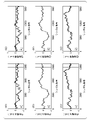
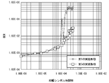
- Each of the internal configuration of the carrier phase retrieval unit of the third embodiment and the functional unit included in the carrier phase retrieval unit uses any of the first database unit, the second database unit, and the third database unit included in the storage unit. It is a block diagram which shows. It is a figure (the 1) which shows the graph of the simulation result. It is a figure (2) which shows the graph of the simulation result.
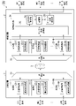
- FIG. 1 is a block diagram showing a configuration of the communication system 100 of the first embodiment.
- the communication system 100 includes a transmission device 1, a reception device 2, and a transmission line 3 connecting between the transmission device 1 and the reception device 2.
- the transmission line 3 is, for example, a multi-mode optical fiber, and transmits optical signals in a plurality of spatial modes.
- the transmission device 1 includes Nt transmission units 11-1 to 11-Nt and an optical coupling unit 10.
- Nt is an integer of 2 or more.
- the transmission unit 11-1 includes a transmission processing unit 12-1 and a carrier wave generation unit 13-1.
- Each of the transmission units 11-2 to 11-Nt includes a transmission processing unit 12-2 to 12-Nt and a carrier wave generation unit 13-2 to 13-Nt corresponding to the branch number of the code.
- Each of the carrier wave generation units 13-1 to 13-Nt generates a carrier wave, that is, a carrier.
- a signal light source is applied as the carrier wave generation units 13-1 to 13-Nt, and each of the carrier wave generation units 13-1 to 13-Nt emits continuous light as a carrier.
- Each of the transmission processing units 12-1 to 12-Nt takes in a data series, which is a series of independent information, as a transmission data series.
- each of the transmission data series taken in by each of the transmission processing units 12-1, 12-2, ..., 12-Nt is referred to as a first data series, a second data series, ..., a Nt data series.
- a vector having Nt transmission data series of the first data series to the Nt data series as a component is called a transmission signal vector x.
- Each of the transmission processing units 12-1 to 12-Nt encodes the first data series to the Nt data series captured by each.
- Each of the transmission processing units 12-1 to 12-Nt is provided with an optical modulator inside.
- Each of the transmission processing units 12-1 to 12-Nt uses an internal optical modulator to use the first data series to the Nt data series of the electric signal encoded by each as a modulation signal, and the corresponding carrier carriers.
- An optical signal is generated from the transmission data series by modulating the continuous light of the carriers emitted by the generation units 13-1 to 13-Nt.
- each of the transmission processing units 12-1 to 12-Nt encodes a first electric input of each of the optical modulators internally provided with each of the transmission processing units 12-1 to 12-Nt.
- An electric signal of the data series to the Nt data series is applied.
- the optical input of each of the light modulators included in each of the transmission processing units 12-1 to 12-Nt is provided with the continuous light of the carrier emitted by the carrier wave generation units 13-1 to 13-Nt corresponding to each. Be done.
- a single continuous light is used as the continuous light given to the optical modulator provided internally by each of the transmission processing units 12-1 to 12-Nt.
- a method of optical branching and optical amplification, a method of performing injection synchronization, or the like is adopted.
- the transmission device 1 of the first embodiment does not require a configuration for performing such a synchronization method, and each of the continuous light of the carriers emitted by the carrier wave generation units 13-1 to 13-Nt is used. , May be asynchronous.
- Each of the transmission processing units 12-1 to 12-Nt of the optical coupling unit 10 combines the generated Nt optical signals and sends them to the transmission line 3.
- the transmission line 3 transmits Nt optical signals to the receiving device 2 as optical signals in each spatial mode.
- the receiving device 2 includes an optical branching unit 20, Nr receiving units 21-1 to 21-Nr, and a signal detecting unit 24.
- Nr is an integer of 2 or more.
- the optical signals of each spatial mode propagating in the transmission line 3 are mixed while propagating in the transmission line 3.
- the optical branching unit 20 branches an optical signal obtained by mixing optical signals of each spatial mode into Nr optical signals.
- the reception unit 21-1 includes a reception processing unit 22-1 and a local oscillation unit 23-1, and similarly, each of the reception units 21-2 to 21-Nr is a reception processing unit 22 corresponding to a branch number of a code. It is provided with -2 to 22-Nr and a local oscillation unit 23-2-23-Nr. Each of the local oscillation units 23-1 to 23-Nr generates and outputs a local oscillation signal used for demodulation.
- the local oscillation light source is applied as the local oscillation units 23-1 to 23-Nr, and each of the local oscillation units 23-1 to 23-Nr is used for coherent detection as the local oscillation signal. It emits continuous light.
- Each of the reception processing units 22-1 to 22-Nr is equipped with a demodulator that performs coherent detection inside.
- Each of the reception processing units 22-1 to 22-Nr gives continuous light emitted by the corresponding local oscillation units 23-1 to 23-Nr to the demodulators provided therein, and gives each of them continuous light.
- the optical signal is demodulated to generate a received data series of the electric signal.
- the number of modes of the optical signal transmitted by the transmission line 3 is "Nm"
- the number Nt of the transmission units 11-1 to 11-Nt and the reception units 21-1 to 21-Nr of the reception device 2 The relationship between the number of units Nr and Nm is Nt ⁇ Nr ⁇ Nm.
- the carrier mode of the independent signal how many modes Nm should be set is predetermined by the user so that Nt ⁇ Nm and Nr ⁇ Nm.
- Nt ⁇ Nm and Nr ⁇ Nm are generally satisfied, the above-mentioned condition Nt ⁇ Nr ⁇ Nm is satisfied.
- Nr Nm in order to perform good MIMO reception.
- the signal detection unit 24 includes a digital signal processing unit 25, a weight matrix calculation unit 26, a storage unit 27, and a carrier phase retrieval unit 28.
- the digital signal processing unit 25 performs the following digital signal processing on the Nr received data series generated by the reception processing units 22-1 to 22-Nr.
- the digital signal processing unit 25 removes distortions and the like generated in each waveform of the Nr received data series by transmission through the transmission line 3 by digital signal processing.
- the digital signal processing unit 25 corrects errors caused in each of the Nr received data series by transmission through the transmission line 3 by digital signal processing.
- Nr reception data series can be separated, and Nt transmission data series can be estimated based on the separated Nr reception data series.
- a vector having Nr received data sequences output by the digital signal processing unit 25 after performing digital signal processing is referred to as a received signal vector y.
- the weight matrix calculation unit 26 is also referred to as an average least squares error (hereinafter referred to as “MMSE” (Minimum Mean Square Error)), which is one of the methods for performing signal separation on the received signal vector y processed by the digital signal processing unit 25.
- MMSE Minimum Mean Square Error
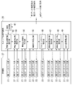
- the storage unit 27 includes a first database unit 31, a second database unit 32, and a third database unit 33.
- the first database unit 31 stores the pre-state estimated value, the post-state estimated value, the pre-error covariance matrix P ⁇ , and the post-error covariance matrix P.
- the pre-state estimated value and the post-state estimated value are vectors, and are expressed as the following equations (1) and (2), respectively.
- the symbol representing the pre-state estimated value of the equation (1) is described as the vector ⁇ ⁇ ⁇
- the symbol representing the post-state estimated value of the equation (2) is described as the vector ⁇ ⁇ .
- the second database unit 32 stores the system noise covariance matrix Q and the observed noise covariance matrix R.
- the third database unit 33 stores the weight matrix calculation unit output data, the pre-output signal, the Kalman gain matrix G, the auxiliary matrix A, the auxiliary matrix B, and the auxiliary matrix C.
- the weight matrix calculation unit output data is data written by the weight matrix calculation unit 26, and includes a weight matrix W and a received signal vector y.
- the pre-output signal is a vector and is expressed as the following equation (3).
- the symbol representing the pre-output signal of the following equation (3 ) is described as a vector ⁇ x-.
- variable indicating the sampling time is k
- the system noise covariance matrix Q and the system noise covariance matrix Q among the vectors and matrices stored in the first database unit 31, the second database unit 32, and the third database unit 33 in the storage unit 27 It is an accurate notation that the vector and the matrix excluding the observed noise covariance matrix R have the variable k indicating the sampling time corresponding to each, but in FIG. 2, the variable k is not attached.
- the variable k is a natural number, but in the following, when a predetermined initial value is shown, "0" may be shown as the value of the variable k.
- the carrier phase recovery unit 28 estimates the disturbing component caused by the phase fluctuation of the carrier wave generating units 13-1 to 13-Nt and the disturbing component caused by the phase fluctuation of the local oscillation units 23-1 to 23-Nr.
- the carrier phase retrieval unit 28 calculates an estimated series of transmission signal vectors x from which the two estimated disturbing components have been removed.
- the carrier phase recovery unit 28 has two interfering components, a phase noise component caused by the phase fluctuation of each light source of the carrier wave generation units 13-1 to 13-Nt, and a local oscillation unit 23-. It is estimated that the phase noise component is caused by the phase fluctuation of each of the light sources of 1 to 23-Nr.
- phase noise components caused by the phase fluctuations of the light sources of the carrier generation units 13-1 to 13-Nt are set to ⁇ 1 t , ⁇ 2 t , ..., ⁇ Nt t , and the local oscillation units 23-1 to 23.
- the phase noise components caused by the phase fluctuation of each of the -Nr light sources be ⁇ 1 r , ⁇ 2 r , ..., ⁇ Nr r .
- Phase noise component vector ⁇ t which is a column vector having ⁇ 1 t , ⁇ 2 t , ..., ⁇ Nt t as components of the phase noise component caused by the phase fluctuation of each light source of the carrier wave generators 13-1 to 13-Nt. Is defined as the following equation (4).
- Phase noise component vector ⁇ r which is a column vector whose components are the phase noise components ⁇ 1 r , ⁇ 2 r , ..., ⁇ Nr r due to the phase fluctuation of each light source of the local oscillation units 23-1 to 23-Nr. Is defined as the following equation (5).
- the vector ⁇ t calculated from the phase noise component vector ⁇ t and the vector ⁇ r calculated from the phase noise component vector ⁇ r are defined as the following equations (6) and (7), respectively.
- the matrix D t in which the components of the vector ⁇ t of the equation (6) are arranged diagonally is defined as the following equation (8), and the matrix Dr r in which the components of the vector ⁇ r of the equation (7) are arranged diagonally. Is defined as the following equation (9).
- the transmission signal vector x is defined as the following equation (10), and the reception signal vector y is defined as the following equation (11).
- Noise added until the received signal vector y is obtained in other words, the transmission line 3 which is a communication path, the transmission processing units 12-1 to 12-Nt of the transmission device 1, and the reception processing unit 22- of the reception device 2.
- the noise vector z that summarizes the noise added by the transmission / reception circuits such as 1 to 22-Nr and the digital signal processing unit 25 of the receiving device 2 is defined as the following equation (12).
- the communication path matrix of the transmission path 3 is defined as the communication path matrix H, which is a matrix having the size of Nr rows and Nt columns. In this case, the relationship shown in the following equation (13) holds.
- the values of the components included in the vector and the matrix shown in the equation (13) are values that change with each sampling time, and it is an accurate notation to add a variable k indicating the sampling time, but here, it is easy to see. For the sake of simplicity, it is shown without k. Even in the description of the following formula, if it is obvious that the variable k indicating the sampling time is added from the contents of the formula, the variable k may be omitted.
- the purpose of MIMO linear reception using the weight matrix W calculated by the weight matrix calculation unit 26 is to multiply the received signal vector y digitally processed by the digital signal processing unit 25 by the weight matrix W to obtain a channel. That is, the coupling between the spatial channels in the transmission line 3 is virtually solved to obtain an estimated sequence of Nt transmission data sequences.
- the purpose of the processing performed by the carrier phase retrieval unit 28 is the phase noise component, which is a column vector of rows in which the phase noise component vector ⁇ t and the phase noise component vector ⁇ r are arranged vertically (Nt + Nr).
- the vector ⁇ is estimated for each sampling time, and the estimated phase noise component vector ⁇ is further removed from the estimated series of Nt transmission data series obtained by MIMO linear reception.
- the carrier phase retrieval unit 28 applies a Kalman filter algorithm to a predefined observation equation and state equation, and performs a process of estimating the phase noise component vector ⁇ for each sampling time based on the observation information obtained for each state. ..
- a Kalman filter algorithm to a predefined observation equation and state equation, and performs a process of estimating the phase noise component vector ⁇ for each sampling time based on the observation information obtained for each state. ..
- the observation equations and the equations of state that need to be defined in advance when using the Kalman filter algorithm will be described.
- ⁇ is the signal-to-noise ratio after propagating in the transmission line 3
- the matrix F is the matrix defined by the following equation (15).
- INT is an identity matrix of N rows and N columns.
- the phase shift caused by the carrier generation units 13-1 to 13-Nt is based on the phase noise component vector ⁇ estimated by the carrier phase recovery unit 28.
- Equation (16) can be said to be an observation equation in which the estimated series of the transmission signal vector x is used as observation information and ⁇ z is used as observation noise.
- the nonlinear function h ( ⁇ ) shown in the following equation (17) is defined.
- the vector v (k) is a vector of (Nt + Nr) rows.
- one specific component among the components of the phase noise component vector ⁇ is set as a steady value, that is, a reference angle.
- the reason why one specific component of the components of the phase noise component vector ⁇ is used as the reference angle is to limit the solution from the plurality of existing least squares solutions to a specific solution.
- the method of selecting one specific component may be arbitrarily determined.
- the phase noise component caused by the phase fluctuation of each of the carrier generation units 13-1 to 13-Nt on the transmitting side is the phase noise that is the reference angle from among ⁇ 1 t , ⁇ 2 t , ..., ⁇ Nt t .
- Select ⁇ 1 t as a component, and set ⁇ 1 t 0 so as not to lose generality.
- the reason why the reference angle is set to "0" is that, for example, when transmitting a signal modulated by a modulation method such as QPSK (Quadra Phase Shift Keying), setting the reference angle to 0 is the minimum square for other unknowns. This is because the solution is also expected to be a meaningful solution in communication.
- the vector v (k) can be expressed as the following equation (20).
- the first component v 1 (k) of the vector v (k) is “0” because it is a reference angle, and the remaining (Nt + Nr-1) v 2
- the components (k) to v Nt + Nr (k) are white noise having an average of 0 and a variance of 2 ⁇ vT.
- ⁇ v is the line width of the carrier wave generation unit 13-1 to 13-Nt and the local oscillation unit 23-1 to 23-Nr
- T is the sampling period.
- the Kalman filter algorithm based on the observation equation shown by equation (18) and the equation of state represented by equation (19) is 1. Preliminary state estimate update, 2. Pre-calculation covariance update, 3. Kalman gain update, 4. Post-state estimated value update, 5. Post-error covariance update, 6. It is an algorithm that repeats a series of operations called signal output value. The operation of "1. Update of the estimated value of the prior state” is expressed by the equation (21).
- the vector ⁇ ⁇ - ( k) is the preliminary state estimated value shown in the equation (1) and is the preliminary state estimated value when the sampling time is (k), and the vector ⁇ ⁇ . (K-1) is the post-state estimated value shown in the equation (2), and the sampling time is the post-state estimated value of (k-1).
- the operation of "2. Pre-error covariance update” is expressed by the following equation (22).
- the matrix P (k) ⁇ is a pre-error covariance matrix when the sampling time is (k), and the matrix P (k-1) has a sampling time (k-1). It is a posterior error covariance matrix in the case of.
- the matrix Q in the equation (22) is a system noise covariance matrix defined by the following equation (23), and E [ ⁇ ] in the following equation (23) is a symbol indicating an expected value operation.
- the matrix G (k) is a Kalman gain matrix.
- the matrix R in the equation (24) is an observed noise covariance matrix defined by the following equation (25), and E [ ⁇ ] in the following equation (25) is a symbol indicating an expected value operation.
- the matrix T in the equation (24) is a matrix defined by the following equation (26).
- the matrix T is a matrix including ⁇ x 1 ⁇ to ⁇ x Nt ⁇ which is a component of the vector ⁇ x ⁇ which is a pre-output signal.
- the matrix T (k) is expressed by omitting the variable k indicating the sampling time from the viewpoint of easy-to-read description of the equation, but the component of the matrix T (k) is. It is a value that changes for each sampling time, and the formal notation considering the sampling time is the following equation (27).
- the vector ⁇ x ⁇ (k) is a pre-output signal as shown in the equation (3) and is a pre-output signal when the sampling time is (k).
- the vector x HD (k) of the equation (28) is a tentative determination value vector obtained by performing a tentative determination according to a predetermined signal modulation method for the vector ⁇ x ⁇ (k) of the pre-output signal.
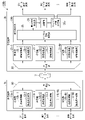
- FIG. 3 shows a functional unit included in the carrier phase retrieval unit 28 that executes the above Kalman filter algorithm, and each functional unit includes a first database unit 31, a second database unit 32, and a third database unit 33 included in the storage unit 27. It is a block diagram which showed which of the above is used.
- the carrier phase recovery unit 28 includes a time update unit 41, a pre-state estimated value update unit 42, a pre-error covariance update unit 43, a pre-output signal calculation unit 44, an auxiliary matrix calculation unit 45, a Kalman gain update unit 46, and a post-state estimation unit. It includes a value update unit 47, a post-error covariance update unit 48, and an output signal calculation unit 49.
- the time update unit 41 generates and outputs a variable k (hereinafter, also referred to as “sampling time k”) indicating the sampling time in the Kalman filter algorithm.
- the pre-state estimated value update unit 42 performs the above-mentioned calculation of “1. Pre-state estimated value update”.
- the prior error covariance update unit 43 performs the calculation of "2. Preliminary miscalculation covariance update” described above.
- the matrix T (k) at the sampling time k used in the calculation is calculated.
- the auxiliary matrix calculation unit 45 uses the three auxiliary matrices A represented by the following equations (31) to (33) used in the above-mentioned "3. Kalman gain update” and “5. Ex-post error covariance update” operations. (K), B (k), C (k) are calculated.
- the Kalman gain update unit 46 performs the calculation of "3. Kalman gain update” described above. However, instead of the equation shown in the equation (24), the following equation (34) is calculated using the auxiliary matrix A (k) calculated by the auxiliary matrix calculation unit 45 and the auxiliary matrix C (k). The Kalman gain matrix G (k) at the sampling time k is calculated.
- the post-state estimated value update unit 47 performs the above-mentioned calculation of "4. Post-state estimated value update”.
- the post-error covariance update unit 48 performs the operation of “5. Post-error covariance update” described above.
- the following equation (35) is calculated using the auxiliary matrix A (k) calculated by the auxiliary matrix calculation unit 45, and the posterior error covariance matrix at the sampling time k is performed. Calculate P (k).
- the output signal calculation unit 49 performs the calculation of "6. Signal output value" described above.
- FIG. 4 is a flowchart showing the flow of processing by the carrier phase retrieval unit 28.
- the weight matrix calculation unit 26 is applied to the case where MIMO linear reception is performed for the captured received signal vector y each time the received signal vector y output by the digital signal processing unit 25 is captured.
- the variable k indicating the sampling time is incremented by 1 in order from 1 to the weight matrix W and the captured received signal vector y, and the processing is performed to write to the third database unit 33 as W (k) and y (k).
- the third database unit 33 stores time-series data such as [W (1), y (1)], [W (2), y (2)], ... As output data of the weight matrix calculation unit. It will be.
- the weight matrix calculation unit 26 stores, for example, a pilot symbol for weight matrix calculation periodically included in the transmission signal vector x and transmitted by the transmission device 1 in an internal storage area, and the transmission device 1 stores the pilot symbol.
- a new weight matrix W is based on the received signal vector output by the digital signal processing unit 25 when the pilot symbol for weight matrix calculation is transmitted and the pilot symbol for weight matrix calculation stored in the internal storage area. Is calculated.
- the vector ⁇ ⁇ (0) is pre-written in the first database unit 31 as the initial value of the post-state estimated value, and the post-error covariance matrix P (0) is pre-written as the initial value of the post-error covariance matrix. It is assumed that it has been written.
- the system noise covariance matrix Q is calculated and written in advance in the second database unit 32 based on the equations (20) and (23), and the observed noise covariance matrix R is described in the equations (14) and (23). It is assumed that it has been calculated and written in advance based on 25).
- ⁇ z (k) and ⁇ z H (k) include the sampling time k as a variable, but as can be seen from the equation (14), ⁇ z changes to the transmission power. If there is no such value, it will be a steady value. Therefore, the change in the observed noise covariance matrix R is a change at an interval sufficiently longer than the interval of the sampling time k, and the observed noise covariance matrix R can be regarded as a steady value.
- the covariance matrix R can be calculated in advance based on the equations (14) and (25).
- the pre-state estimated value update unit 42 When the pre-state estimated value update unit 42 receives the sampling time k from the time update unit 41, the vector ⁇ ⁇ (k-1) which is the post-state estimated value from the first database unit 31 based on the received sampling time k. Is read and the calculation of the equation (21) is performed, that is, the read vector ⁇ ⁇ (k-1) is used as the vector ⁇ ⁇ ⁇ (k) which is the pre-state estimated value.
- the pre-state estimated value update unit 42 writes the vector ⁇ ⁇ ⁇ (k), which is the pre-state estimated value, into the first database unit 31 and updates it.
- the advance state estimation value update unit 42 deletes the vector ⁇ ⁇ - (k - 1).
- Vector ⁇ ⁇ - ( k) is written and updated.
- the advance state estimation value update unit 42 outputs the sampling time k to the advance error covariance update unit 43 (step S2).
- the pre-error covariance update unit 43 When the pre-error covariance update unit 43 receives the sampling time k from the pre-state estimated value update unit 42, the pre-error covariance update unit 43 reads out the system noise covariance matrix Q from the second database unit 32 based on the received sampling time k. The pre-error covariance update unit 43 reads the post-error covariance matrix P (k-1) from the first database unit 31. The pre-error covariance update unit 43 performs the calculation of the equation (22) based on the read system noise covariance matrix Q and the post-error covariance matrix P (k-1), and performs the pre-error covariance matrix P. -Calculate (k).
- the prior error covariance update unit 43 writes the calculated prior error covariance matrix P ⁇ (k) in the first database unit 31 and updates it.
- the pre-error covariance update unit 43 uses the pre - error covariance matrix P- (k-). 1) is deleted and the prior error covariance matrix P- ( k) is written and updated.
- the pre-error covariance update unit 43 outputs the sampling time k to the pre-output signal calculation unit 44 (step S3).
- the pre-output signal calculation unit 44 When the pre-output signal calculation unit 44 receives the sampling time k from the pre-error covariance update unit 43, the pre-state estimated value vector ⁇ ⁇ ⁇ (k) is received from the first database unit 31 based on the received sampling time k. ) Is read.
- the pre-output signal calculation unit 44 reads the weight matrix W (k) and the received signal vector y (k) from the third database unit 33.
- the pre-output signal calculation unit 44 uses the following equation (36) based on the read pre-state estimated value vector ⁇ ⁇ ⁇ (k), the weight matrix W (k), and the received signal vector y (k). Is performed to calculate the vector ⁇ x- ( k) which is a pre-output signal.
- the pre-output signal calculation unit 44 includes a calculated pre-output signal vector ⁇ x- ( k), a pre-state estimated value vector ⁇ ⁇ - ( k), a weight matrix W (k), and a received signal vector. Based on y (k), the matrix T (k) shown in the equations (26) and (27) is calculated. The pre-output signal calculation unit 44 writes the calculated vector ⁇ x ⁇ (k), which is the pre-output signal, to the third database unit 33 and updates it. When the vector ⁇ x- (k - 1) at the sampling time k-1 is written in the third database unit 33, the pre-output signal calculation unit 44 deletes the vector ⁇ x- (k - 1) to form a vector. ⁇ X - Write (k) to update. The pre-output signal calculation unit 44 outputs the calculated matrix T (k) and the sampling time k to the auxiliary matrix calculation unit 45 (step S4).
- the auxiliary matrix calculation unit 45 takes in the matrix T (k) output by the pre-output signal calculation unit 44.
- the auxiliary matrix calculation unit 45 reads the prior error covariance matrix P ⁇ (k) from the first database unit 31 based on the sampling time k received from the pre-output signal calculation unit 44.
- the auxiliary matrix calculation unit 45 reads the observed noise covariance matrix R from the second database unit 32.
- the auxiliary matrix calculation unit 45 is based on the fetched matrix T (k), the read prior error covariance matrix P ⁇ ( k), and the observed noise covariance matrix R, and the equations (31), (32), ( 33) is performed to calculate the auxiliary matrices A (k), B (k), and C (k).
- the auxiliary matrix calculation unit 45 writes and updates the calculated auxiliary matrices A (k), B (k), and C (k) to the third database unit 33.
- the auxiliary matrix calculation unit 45 uses the auxiliary matrix.
- a (k-1), B (k-1), and C (k-1) are deleted, and auxiliary matrices A (k), B (k), and C (k) are written and updated.
- the auxiliary matrix calculation unit 45 outputs the sampling time k to the Kalman gain update unit 46 (step S5).
- the Kalman gain update unit 46 When the Kalman gain update unit 46 receives the sampling time k from the auxiliary matrix calculation unit 45, the Kalman gain update unit 46 reads out the auxiliary matrices A (k) and C (k) from the third database unit 33 based on the received sampling time k. The Kalman gain update unit 46 calculates the Kalman gain matrix G (k) by performing the calculation of the equation (34) based on the read auxiliary matrices A (k) and C (k). The Kalman gain update unit 46 writes the calculated Kalman gain matrix G (k) in the third database unit 33 and updates it.
- the Kalman gain update unit 46 deletes the Kalman gain matrix G (k-1) and makes the Kalman gain.
- the matrix G (k) is written and updated.
- the Kalman gain update unit 46 outputs the sampling time k to the post-state estimated value update unit 47 (step S6).
- the ex post facto state estimated value update unit 47 receives the sampling time k from the Kalman gain update unit 46, the Kalman gain matrix G (k) and the pre-output signal are used from the third database unit 33 based on the received sampling time k.
- the post-state estimated value update unit 47 reads the vector ⁇ ⁇ ⁇ (k), which is the pre-state estimated value, from the first database unit 31.
- the ex post facto state estimation value update unit 47 calculates the tentative determination value vector x HD (k) by performing a tentative determination according to a predetermined signal modulation method for the vector ⁇ x ⁇ (k) which is a pre-output signal. ..
- the post-state estimated value update unit 47 uses the calculated tentative determination value vector x HD (k), the read pre-state estimated value vector ⁇ ⁇ - ( k), the Kalman gain matrix G (k), and the pre-output signal. Based on a certain vector ⁇ x ⁇ (k), the calculation of the equation (28) is performed to calculate the vector ⁇ ⁇ (k) which is the estimated value of the ex post facto state.
- the post-state estimated value update unit 47 writes the calculated vector ⁇ ⁇ (k), which is the post-state estimated value, into the first database unit 31 and updates it.
- the post-state estimated value update unit 47 deletes the vector ⁇ ⁇ (k-1) and the vector ⁇ . Write ⁇ (k) and update.
- the post-state estimated value update unit 47 outputs the sampling time k to the post-error covariance update unit 48 (step S7).
- the Kalman gain matrix G (k) and the auxiliary matrix from the third database unit 33 are based on the received sampling time k.
- the posterior error covariance update unit 48 reads the posterior error covariance matrix P ⁇ (k) from the first database unit 31.
- the post-error covariance update unit 48 performs the calculation of equation (35) based on the read Kalman gain matrix G (k), the auxiliary matrix A (k), and the pre-error covariance matrix P ⁇ (k). This is done to calculate the posterior error covariance matrix P (k).
- the posterior error covariance update unit 48 writes and updates the calculated posterior error covariance matrix P (k) in the first database unit 31.
- the posterior error covariance update unit 48 uses the posterior error covariance matrix P (k-1). Is deleted and the posterior error covariance matrix P (k) is written and updated.
- the post-error covariance update unit 48 outputs the sampling time k to the output signal calculation unit 49 (step S9).
- the output signal calculation unit 49 When the output signal calculation unit 49 receives the sampling time k from the post-error covariance update unit 48, the output signal calculation unit 49 obtains the vector ⁇ ⁇ (k), which is the post-state estimated value, from the first database unit 31 based on the received sampling time k. read out. The output signal calculation unit 49 performs the calculation of the equation (30) based on the vector ⁇ ⁇ (k) which is the read post-state estimated value, and obtains the vector ⁇ x (k) which is the estimated series of the transmission signal vector x. The calculated first data estimation series, the second data estimation series, ..., The Nt data estimation series, which are the components of the calculated vector ⁇ x (k), are output to the outside.
- the output signal calculation unit 49 refers to the third database unit 33, and does the third database unit 33 store the received signal vector y (k + 1) corresponding to the sampling time k + 1 obtained by adding 1 to the current sampling time k? It is determined whether or not (step S10).
- the output signal calculation unit 49 determines that the third database unit 33 stores the received signal vector y (k + 1) corresponding to the sampling time k + 1 (steps S10, Yes)
- the output signal calculation unit 49 sets the sampling time k to the time update unit 41. Output to.
- the time update unit 41 sets the value obtained by adding 1 to the sampling time k as the new sampling time k, and outputs the new sampling time k to the advance state estimation value update unit 42 (step S11). After that, the processing after step S2 is performed.
- step S10, No when the output signal calculation unit 49 determines that the third database unit 33 does not store the received signal vector y (k + 1) corresponding to the sampling time k + 1 (step S10, No), the process ends.
- the transmission line 3 is a multi-mode optical fiber, and a plurality of optical signals are transmitted in a plurality of spatial modes.
- the transmission device 1 includes a plurality of transmission units 11-1 to 11-Nt, and each of the plurality of transmission units 11-1 to 11-Nt has each of the plurality of transmission units 11-1 to 11-Nt based on the transmission data sequence given to each.
- the continuous light of the carrier wave output by the carrier wave generation units 13-1 to 13-Nt is modulated to generate a transmission optical signal, and the generated transmission optical signal is transmitted to the transmission line 3.
- the receiving device 2 includes a plurality of receiving units 21-1 to 21-Nr, and the plurality of receiving units 21-1 to 21-Nr transmit a plurality of optical signals transmitted by the transmission line 3 in a plurality of spatial modes.
- the received optical signal received is demodulated based on the continuous light as the local oscillation signal output by the local oscillation units 23-1 to 23-Nr, respectively, to generate a reception data series.
- the signal detection unit 24 includes a weight matrix calculation unit 26 and a carrier phase retrieval unit 28, and the weight matrix calculation unit 26 calculates a weight matrix W to be used when performing MIMO linear reception with respect to a received data series. do.
- the carrier phase recovery unit 28 is a plurality of carrier wave generation units which are interference components generated because the plurality of carrier wave generation units 13-1 to 13-Nt and the plurality of local oscillation units 23-1 to 23-Nr are asynchronous.
- the phase noise component caused by the phase fluctuation of the light source of each of the 13-1 to 13-Nt and the plurality of local oscillation units 23-1 to 23-Nt is used as the state information, and the post-state information is used as the pre-state information.
- the post-state information calculated by the state equation, the received data series, and the weight matrix as the observation information.
- the Kalman filter algorithm is applied to the predetermined observation equation to calculate the observation information, and the posterior state estimate of the disturbing component is calculated.
- the estimation series of the transmission data series from which the phase noise component caused by the phase fluctuation of the light source of each of the units 13-1 to 13-Nt and the plurality of local oscillation units 23-1 to 23-Nt is removed is calculated.
- the light source of each of the carrier wave generation units 13-1 to 13-Nt of the transmission device 1 and the local oscillation unit 23-1 of the reception device 2 Asynchronous light sources can be applied to the light sources of each of ⁇ 23-Nr. In other words, it becomes possible to transmit a plurality of signals in a plurality of modes of the same transmission medium in a state where the carrier wave generated by the transmitting device 1 and the locally oscillating signal generated by the receiving device 2 are asynchronous.
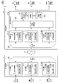
- FIG. 5 is a block diagram showing a configuration of the communication system 100a of the second embodiment.
- the communication system 100a includes a transmission device 1, a reception device 2a, and a transmission line 3 connecting between the transmission device 1 and the reception device 2a.
- the receiving device 2a includes an optical branching unit 20, Nr receiving units 21-1 to 21-Nr, and a signal detecting unit 24a.
- the signal detection unit 24a includes a digital signal processing unit 25, a weight matrix calculation unit 26, a storage unit 27a, and a carrier phase retrieval unit 28a.
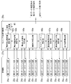
- the storage unit 27a includes a first database unit 31a, a second database unit 32a, and a third database unit 33a.
- the first database unit 31a stores the pre-state estimated value, the post-state estimated value, the pre-error covariance matrix P f ⁇ , and the post-error covariance matrix P f .
- the pre-state estimated value and the post-state estimated value are vectors, and are expressed as the following equations (37) and (38), respectively.
- the symbol representing the pre-state estimated value of the equation (37) is described as the vector ⁇ ⁇ -
- the symbol representing the post-state estimated value of the equation (38 ) is described as the vector ⁇ ⁇ .
- the second database unit 32a stores the system noise covariance matrix Q f and the observed noise covariance matrix R.
- the third database unit 33a stores the weight matrix calculation unit output data, the pre-output signal which is the vector ⁇ x ⁇ , the Kalman gain matrix G f , the auxiliary matrix A, the auxiliary matrix B, and the auxiliary matrix C.
- the weight matrix calculation unit output data is data written by the weight matrix calculation unit 26 as in the first embodiment, and includes the weight matrix W and the received signal vector y. Similar to FIG. 2 of the first embodiment, FIG. 6 also shows the sample without the variable k indicating the sampling time.
- the carrier phase recovery unit 28a estimates the disturbing component caused by the phase fluctuation of the carrier wave generating units 13-1 to 13-Nt and the disturbing component caused by the phase fluctuation of the local oscillation units 23-1 to 23-Nr.
- the carrier phase retrieval unit 28a calculates an estimated sequence of the transmission signal vector x from which the two detected interfering components have been removed.
- the carrier phase recovery unit 28a has two interference components, a phase noise component and a frequency offset component caused by the phase fluctuation of the light sources of the carrier wave generation units 13-1 to 13-Nt. And the interference component called the phase noise component and the frequency offset component caused by the phase fluctuation of each of the light sources of the local oscillation units 23-1 to 23-Nr are estimated.
- the frequency offset components caused by the frequency fluctuations of the light sources of the carrier wave generation units 13-1 to 13-Nt are set to ⁇ 1 t , ⁇ 2 t , ..., ⁇ Nt t , and the local oscillation units 23-1 to 23.
- the frequency offset component which is a column vector having the frequency offset components ⁇ 1 t , ⁇ 2 t , ..., ⁇ Nt t due to the frequency fluctuation of each of the light sources of the carrier wave generation units 13-1 to 13-Nt.
- the vector ⁇ t is defined as the following equation (39).
- Frequency offset component vector ⁇ which is a column vector whose components are frequency offset components, ⁇ 1 r , ⁇ 2 r , ..., ⁇ Nr r , which are caused by frequency fluctuations of each light source of the local oscillation units 23-1 to 23-Nr. r is defined as the following equation (40).
- the vector ⁇ including the phase noise component vectors ⁇ t and ⁇ r to be estimated by the carrier phase retrieval unit 28a and the frequency offset component vectors ⁇ t and ⁇ r is defined by the following equation (41).
- equation of state for the vector ⁇ estimated by the carrier phase retrieval unit 28a can be expressed as the following equation (42).
- the matrix M is expressed as the following equation (43), and the vector ⁇ (k) is expressed as the following equation (44).
- the symbol of the following equation (46) means a matrix in which the (i, i) component of the unit matrix of m rows and n columns is set to 0.
- the vector v (k) shown on the right side of the equation (44) is the vector shown by the equation (20) in the first embodiment.
- the observation equation in the second embodiment is the equation shown in the equation (18) as in the first embodiment, and the observation equation represented by the equation (18) and the equation of state represented by the equation (42).
- the Kalman filter algorithm based on 1a. Pre-state estimated value update, 2a. Pre-miscalculated covariance update, 3a. Kalman gain update, 4a. Post-state estimated value update, 5a. Post-error covariance update, 6a. It is an algorithm that repeats a series of operations called signal output value. The operation of "1a. Update of the estimated value of the prior state" is expressed by the equation (47).
- the vector ⁇ ⁇ ⁇ (k) is the preliminary state estimated value shown in the equation (37) and is the preliminary state estimated value when the sampling time is (k), and the vector ⁇ ⁇ . (K-1) is the ex-post state estimated value shown in the equation (38), and is the ex-post state estimated value when the sampling time is (k-1).
- the operation of "2a. Pre-error covariance update” is expressed by the following equation (48).
- the matrix P (k) ⁇ is a pre-error covariance matrix when the sampling time is (k), and the matrix P (k-1) has a sampling time (k-1).
- the matrix Q f which is the posterior error covariance matrix in the case of, is a system noise covariance matrix defined by the following equation (49), and E [ ⁇ ] in the following equation (49) indicates an expected value operation. It is a symbol.
- the matrix G f (k) is the Kalman gain matrix in the second embodiment
- the matrix R is the observation represented by the equation (25) as in the first embodiment. It is a noise covariance matrix.
- the matrix T f is a matrix defined by the following equation (51).
- the matrix T shown in the formula (51) is the matrix shown in the formula (26) in the first embodiment.
- the matrix T f (k) is expressed by omitting the variable k indicating the sampling time from the viewpoint of easy-to-read description of the equation, but the component of the matrix T f (k). Is a value that changes for each sampling time, and the formal notation in consideration of the sampling time is the following equation (52).
- FIG. 7 shows a functional unit included in the carrier phase retrieval unit 28a that executes the Kalman filter algorithm of the second embodiment described above, and each functional unit includes a first database unit 31a and a second database unit 32a included in the storage unit 27a. It is a block diagram which showed which of 3rd database part 33a is used.
- the carrier phase recovery unit 28a includes a time update unit 41, a pre-state estimated value update unit 42a, a pre-error covariance update unit 43a, a pre-output signal calculation unit 44a, an auxiliary matrix calculation unit 45a, a Kalman gain update unit 46a, and a post-state estimation. It includes a value update unit 47a, a post-error covariance update unit 48a, and an output signal calculation unit 49a.
- the pre-state estimated value update unit 42a performs the above-mentioned calculation of "1a. Pre-state estimated value update”.
- the prior error covariance update unit 43a performs the calculation of "2. Preliminary miscalculation covariance update” described above.
- the pre-output signal calculation unit 44a is of the pre-output signal vector ⁇ x- ( k) at the sampling time k used in the calculation of the above-mentioned "4a.
- Post-state estimated value update and the above-mentioned "3a. Kalman gain update”.
- the matrix T f (k) at the sampling time k used in the calculation is calculated.
- the auxiliary matrix calculation unit 45a has three auxiliary matrices A represented by the following equations (56) to (58) used in the above-mentioned "3a. Kalman gain update” and “5a. Ex-post error covariance update” operations. (K), B (k), C (k) are calculated.
- the Kalman gain update unit 46a performs the above-mentioned "3a. Kalman gain update” calculation. However, instead of the equation shown in the equation (50), the following equation (59) is calculated using the auxiliary matrix A (k) calculated by the auxiliary matrix calculation unit 45a and the auxiliary matrix C (k). The Kalman gain matrix G f (k) is calculated.
- the post-state estimated value update unit 47a performs the above-mentioned calculation of “4a. Post-state estimated value update”.
- the post-error covariance update unit 48a performs the above-mentioned calculation of "5a. Post-error covariance update”.
- the operation of the equation (60) using the auxiliary matrix A (k) calculated by the auxiliary matrix calculation unit 45a is performed to perform the post-error covariance matrix P f (k). Is calculated.
- the output signal calculation unit 49a performs the calculation of the above-mentioned "6a. Signal output value”.
- FIG. 8 is a flowchart showing the flow of processing by the carrier phase retrieval unit 28a.
- the weight matrix calculation unit 26 receives each time the received signal vector y output by the digital signal processing unit 25 is captured, with respect to the captured received signal vector y.
- the variable k indicating the sampling time is incremented by 1 in order from 1 to the weight matrix W applied when performing MIMO linear reception and the captured signal vector y, and the third is W (k) and y (k).
- the third database unit 33a stores time-series data such as [W (1), y (1)], [W (2), y (2)], ... As output data of the weight matrix calculation unit. It will be.
- the weight matrix calculation unit 26 stores, for example, a pilot symbol for weight matrix calculation periodically included in the transmission signal vector x and transmitted by the transmission device 1 in an internal storage area, and the transmission device 1 stores the pilot symbol.
- a new weight matrix W is based on the received signal vector output by the digital signal processing unit 25 when the pilot symbol for weight matrix calculation is transmitted and the pilot symbol for weight matrix calculation stored in the internal storage area. Is calculated.
- the vector ⁇ ⁇ (0) is pre-written in the first database unit 31a as the initial value of the post-state estimated value, and the post-error covariance matrix P f (0) is written as the initial value of the post-error covariance matrix. It is assumed that it has been written in advance.
- the system noise covariance matrix Q f is calculated and written in advance in the second database unit 32a based on the equations (44) and (49), and the observed noise covariance matrix R is described in the equation (14), It is assumed that it has been calculated and written in advance based on (25).
- Each of the pre-state estimated value update unit 42a and the pre-error covariance update unit 43a stores the matrix M represented by the equation (43) in advance in the internal storage area.
- the pre-state estimated value update unit 42a When the pre-state estimated value update unit 42a receives the sampling time k from the time update unit 41, the vector ⁇ ⁇ (k-1) which is the post-state estimated value is received from the first database unit 31a based on the received sampling time k. Is read. The pre-state estimated value update unit 42a performs an operation of the equation (47) based on the vector ⁇ ⁇ (k-1) which is the read post-state estimated value and the matrix M stored in the internal storage area. The vector ⁇ ⁇ - ( k), which is an estimated value of the prior state, is calculated. The pre-state estimated value update unit 42a writes the calculated vector ⁇ ⁇ ⁇ (k), which is the pre-state estimated value, into the first database unit 31a and updates it.
- the advance state estimation value update unit 42a deletes the vector ⁇ ⁇ ⁇ (k-1).
- Vector ⁇ ⁇ - ( k) is written and updated.
- the pre-state estimated value update unit 42a outputs the sampling time k to the pre-error covariance update unit 43a (step Sa2).
- the pre-error covariance update unit 43a When the pre-error covariance update unit 43a receives the sampling time k from the pre-state estimated value update unit 42a, the system noise covariance matrix Q f is read from the second database unit 32a based on the received sampling time k.
- the pre-error covariance update unit 43a reads the post-error covariance matrix P f (k-1) from the first database unit 31a.
- the pre-error covariance update unit 43a is based on the read system noise covariance matrix Q f , the post-error covariance matrix P f (k-1), and the matrix M stored in the internal storage area. 48) is performed to calculate the pre-error covariance matrix P f ⁇ (k).
- the prior error covariance update unit 43a writes the calculated prior error covariance matrix P f ⁇ (k) to the first database unit 31a and updates it.
- the pre-error covariance update unit 43a uses the pre-error covariance matrix P f-( k - 1). Delete k-1) and write and update the prior error covariance matrix P f- (k ) .
- the pre-error covariance update unit 43a outputs the sampling time k to the pre-output signal calculation unit 44a (step Sa3).
- the pre-output signal calculation unit 44a When the pre-output signal calculation unit 44a receives the sampling time k from the pre-error covariance update unit 43a, the pre-state estimated value vector ⁇ ⁇ ⁇ (k) is obtained from the first database unit 31a based on the received sampling time k. ) Is read.
- the pre-output signal calculation unit 44a reads the weight matrix W (k) and the received signal vector y (k) from the third database unit 33a.
- the pre-output signal calculation unit 44a includes a vector ⁇ ⁇ - ( k) included in the read pre - state estimated value vector ⁇ ⁇ - (k), a weight matrix W (k), and a received signal vector y (k). Based on the above, the calculation of the equation (36) is performed to calculate the vector ⁇ x ⁇ (k) which is a pre-output signal.
- the pre-output signal calculation unit 44a includes a calculated pre-output signal vector ⁇ x- ( k), a pre-state estimated value vector ⁇ ⁇ - ( k), a weight matrix W (k), and a received signal vector. Based on y (k), the matrix T (k) shown in the equations (26) and (27) is calculated. The pre-output signal calculation unit 44a calculates the matrix T f (k) shown in the equations (51) and (52) based on the calculated matrix T (k). The pre-output signal calculation unit 44a writes the calculated vector ⁇ x ⁇ (k), which is the pre-output signal, to the third database unit 33a and updates it.
- the pre-output signal calculation unit 44a deletes the vector ⁇ x- (k - 1) to form a vector.
- ⁇ X - Write (k) to update.
- the pre-output signal calculation unit 44a outputs the calculated matrix T f (k) and the sampling time k to the auxiliary matrix calculation unit 45a (step Sa4).
- the auxiliary matrix calculation unit 45a takes in the matrix T f (k) output by the pre-output signal calculation unit 44a.
- the auxiliary matrix calculation unit 45a reads out the pre-error covariance matrix P f ⁇ (k) from the first database unit 31a based on the sampling time k received from the pre-output signal calculation unit 44a.
- the auxiliary matrix calculation unit 45a reads the observed noise covariance matrix R from the second database unit 32a.
- the auxiliary matrix calculation unit 45 uses equations (56), (57), based on the fetched matrix T (k), the read prior error covariance matrix P f ⁇ (k), and the observed noise covariance matrix R.
- the operation of (58) is performed to calculate the auxiliary matrices A (k), B (k), and C (k).
- the auxiliary matrix calculation unit 45a writes the calculated auxiliary matrices A (k), B (k), and C (k) to the third database unit 33a and updates them.
- the auxiliary matrix calculation unit 45a uses the auxiliary matrix.
- a (k-1), B (k-1), and C (k-1) are deleted, and auxiliary matrices A (k), B (k), and C (k) are written and updated.
- the auxiliary matrix calculation unit 45a outputs the sampling time k to the Kalman gain update unit 46a (step Sa5).
- the Kalman gain update unit 46a When the Kalman gain update unit 46a receives the sampling time k from the auxiliary matrix calculation unit 45a, the Kalman gain update unit 46a reads out the auxiliary matrices A (k) and C (k) from the third database unit 33a based on the received sampling time k. The Kalman gain update unit 46a calculates the Kalman gain matrix G f (k) by performing the calculation of the equation (59) based on the read auxiliary matrices A (k) and C (k). The Kalman gain update unit 46a writes the calculated Kalman gain matrix G f (k) to the third database unit 33a and updates it.
- the Kalman gain update unit 46a deletes the Kalman gain matrix G f (k-1).
- the Kalman gain matrix G f (k) is written and updated.
- the Kalman gain update unit 46a outputs the sampling time k to the post-state estimated value update unit 47a (step Sa6).
- the ex post facto state estimated value update unit 47a receives the sampling time k from the Kalman gain update unit 46a, the Kalman gain matrix G f (k) and the pre-output signal from the third database unit 33a are based on the received sampling time k.
- the vector ⁇ x- ( k) is read out.
- the post-state estimated value update unit 47a reads the vector ⁇ ⁇ - ( k), which is the pre-state estimated value, from the first database unit 31a.
- the ex post facto state estimation value update unit 47a calculates the tentative determination value vector x HD (k) by performing a tentative determination according to a predetermined signal modulation method for the vector ⁇ x ⁇ (k) which is a pre-output signal. ..
- the post-state estimated value update unit 47a includes the calculated tentative determination value vector x HD (k), the read pre-state estimated value vector ⁇ ⁇ - ( k), the Kalman gain matrix G f (k), and the pre-output signal. Based on the vector ⁇ x ⁇ (k), which is, the calculation of the equation (53) is performed to calculate the vector ⁇ ⁇ (k) which is the estimated value of the ex post facto state.
- the post-state estimated value update unit 47a writes the calculated vector ⁇ ⁇ (k), which is the post-state estimated value, into the first database unit 31a and updates it.
- the post-state estimated value update unit 47a deletes the vector ⁇ ⁇ (k-1) and the vector ⁇ . Write ⁇ (k) and update.
- the post-state estimated value update unit 47a outputs the sampling time k to the post-error covariance update unit 48a (step Sa7).
- the Kalman gain matrix G f (k) and the auxiliary are received from the third database unit 33a based on the received sampling time k.
- the posterior error covariance update unit 48a reads the posterior error covariance matrix P f ⁇ (k) from the first database unit 31a.
- the posterior error covariance update unit 48a is based on the read Kalman gain matrix G f (k), the auxiliary matrix A (k), and the pre-error covariance matrix P f ⁇ (k). An operation is performed to calculate the posterior error covariance matrix P f (k).
- the posterior error covariance update unit 48 writes and updates the calculated posterior error covariance matrix P f (k) in the first database unit 31a.
- the posterior error covariance update unit 48a uses the posterior error covariance matrix P f (k-). Delete 1) and write and update the posterior error covariance matrix P f (k).
- the post-error covariance update unit 48a outputs the sampling time k to the output signal calculation unit 49 (step Sa9).
- the output signal calculation unit 49a When the output signal calculation unit 49a receives the sampling time k from the post-error covariance update unit 48a, the output signal calculation unit 49a obtains the vector ⁇ ⁇ (k) which is the post-state estimated value from the first database unit 31a based on the received sampling time k. read out.
- the output signal calculation unit 49a performs the calculation of the equation (55) based on the vector ⁇ ⁇ (k) which is the read posterior state estimation value, and obtains the vector ⁇ x (k) which is the estimation series of the transmission signal vector x.
- the Nt data estimation series which are the components of the calculated vector ⁇ x (k), are output to the outside.
- the output signal calculation unit 49a refers to the third database unit 33a, and does the third database unit 33a store the received signal vector y (k + 1) corresponding to the sampling time k + 1 obtained by adding 1 to the current sampling time k? It is determined whether or not (step Sa10).
- the output signal calculation unit 49a determines that the third database unit 33 stores the received signal vector y (k + 1) corresponding to the sampling time k + 1 (steps Sa10, Yes)
- the output signal calculation unit 49a sets the sampling time k to the time update unit 41. Output to.
- the time update unit 41 sets the value obtained by adding 1 to the sampling time k as the new sampling time k, and outputs the new sampling time k to the advance state estimation value update unit 42a (step Sa11). After that, the processing after step Sa2 is performed.
- the plurality of carrier wave generating units 13-1 to 13-Nt and the plurality of local oscillation units 23-1 to 23-Nt which are the disturbing components of the first embodiment.
- the phase noise component caused by the phase fluctuation of the light source possessed by each of the above the light sources possessed by each of the plurality of carrier wave generators 13-1 to 13-Nt and the plurality of local oscillators 23-1 to 23-Nt.
- the frequency offset component due to the frequency fluctuation of is included.
- the plurality of carrier wave generation units 13 together with the phase noise component caused by the phase fluctuation of the light source of each of the plurality of carrier wave generation units 13-1 to 13-Nt and the plurality of local oscillation units 23-1 to 23-Nt. It is possible to remove the frequency offset component caused by the frequency fluctuation of the light source of each of the -1 to 13-Nt and the plurality of local oscillation units 23-1 to 23-Nt.
- the light source of each of the carrier wave generation units 13-1 to 13-Nt of the transmission device 1 and the local oscillation unit 23-1 of the reception device 2 It becomes possible to apply an asynchronous light source to the light source of each of ⁇ 23-Nr. In other words, it becomes possible to transmit a plurality of signals in a plurality of modes of the same transmission medium in a state where the carrier wave generated by the transmitting device 1 and the locally oscillating signal generated by the receiving device 2a are asynchronous.
- the frequency caused by the frequency fluctuation of the light source possessed by each of the plurality of carrier wave generation units 13-1 to 13-Nt and the plurality of local oscillation units 23-1 to 23-Nt Since the offset component is removed, it is possible to estimate the estimation series of the transmission signal vector with higher accuracy than that of the first communication system 100.
- the received signal vector y is a vector having Nr received data sequences output by the digital signal processing unit 25 after performing digital signal processing.
- the weight matrix calculation unit 26 may directly capture the Nr reception data series output by the reception processing units 22-1 to 22-Nr without the digital signal processing unit 25. In this case, the Nr reception data series output by the reception processing units 22-1 to 22-Nr becomes the reception signal vector y.
- the Kalman gain update units 46 and 46a have a predetermined signal modulation method with respect to the prior signal estimation value vector ⁇ x ⁇ (k) in the equations (28) and (53). Therefore, the tentative determination value vector x HD (k) obtained by performing the tentative determination according to the above was used. Therefore, depending on the accuracy of the advance signal estimation value vector ⁇ x ⁇ (k), the tentative determination value vector x HD (k) may include an error, which deteriorates the carrier phase retrieval performance.
- the third embodiment includes a configuration in which a predetermined pilot symbol is used instead of the provisional determination value vector x HD (k) so as not to deteriorate the performance of carrier phase retrieval.
- FIG. 9 is a block diagram showing the configuration of the communication system 100b according to the third embodiment.
- the communication system 100b includes a transmission device 1b, a transmission line 3, and a reception device 2b.
- the transmission device 1b includes transmission units 11b-1 to 11b-Nt and an optical coupling unit 10.
- the transmission unit 11b-1 includes a transmission processing unit 12b-1 and a carrier wave generation unit 13-1, and similarly, each of the transmission units 11b-2 to 11b-Nt is a transmission processing unit 12b corresponding to a branch number of a code.
- -2 to 12b-Nt and carrier wave generation units 13-2 to 13-Nt are provided.
- the transmission processing units 12b-1 to 12b-Nt are generated from the first data series to the Nt data series to be taken in by each of the transmission processing units 12-1 to 12-Nt in addition to the configuration provided in the transmission processing units 12-1 to 12-Nt of the first embodiment.
- a predetermined pilot symbol such as the beginning of a signal frame is periodically inserted.
- the receiving device 2b includes an optical branching unit 20, receiving units 21-1 to 21-Nr, and a signal detecting unit 24b.
- the signal detection unit 24b includes a digital signal processing unit 25, a weight matrix calculation unit 26, a storage unit 27, and a carrier phase retrieval unit 28b.
- the carrier phase retrieval unit 28b is provided with the Kalman gain update unit 46b in place of the Kalman gain update unit 46 included in the carrier phase retrieval unit 28 of the first embodiment. It has the same configuration as the carrier phase retrieval unit 28 of the above.
- the carrier phase retrieval unit 28b stores in advance a predetermined pilot symbol to be inserted by the transmission device 1b and a period in which the pilot symbol is inserted in the internal storage area.
- the pilot symbol is a vector including Nt data series as in the transmission signal vector x.
- the Kalman gain update unit 46b is a sampling time k in which a part of the calculation of the equation (28), that is, a pilot symbol periodically inserted by the transmission processing units 12b-1 to 12b-Nt is included in the received signal vector y (k).
- the calculation of the equation (28) performed at the timing of the calculation is performed using the pilot symbol stored in advance in the internal storage area instead of the provisional determination value vector x HD (k).
- a part of the provisional determination value vector x HD (k) is replaced with a pilot symbol known in the transmitting device 1b and the receiving device 2b, so that the operation is performed. Even when the accuracy of the estimated value vector ⁇ x ⁇ (k) is low, it is possible to prevent the carrier phase retrieval performance from being deteriorated.
- the configuration using the pilot symbol is added to the first embodiment, but the configuration using the pilot symbol is also used for the communication system 100a of the second embodiment.
- the pilot symbol can be applied instead of a part of the tentative determination value vector x HD (k) in the operation of the equation (53), and the vector ⁇ which is the preliminary signal estimation value can be applied. Even when the accuracy of x ⁇ (k) is low, it is possible to prevent the carrier phase retrieval performance from being deteriorated.
- the transmission processing units 12b-1 to 12b-Nt periodically insert a predetermined pilot symbol such as the beginning of a signal frame.
- the pilot symbol may be inserted periodically every several hundred symbols, or the cycle for inserting the pilot symbol may be adaptively and variably changed according to the communication situation.
- a means for notifying the Kalman gain updating unit 46b of the carrier phase retrieval unit 28b of the receiving device 2b of the timing at which the pilot symbol is inserted is required.
- the weight matrix calculation unit 26 may use the pilot symbol for weight matrix calculation used for calculating the weight matrix W.
- the receiving device 2b stores in advance instead of the vector x HD (k).
- the vector ⁇ ⁇ (k) which is the estimated value of the ex post facto state, can be calculated by using the pilot symbol. Therefore, even when the accuracy of the vector ⁇ x- ( k), which is an estimated value of the advance signal, is low, it is possible to prevent the performance of carrier phase retrieval from being deteriorated, and the first and second embodiments can be made. Compared with the configuration of, it is possible to calculate the estimated sequence of the transmission data sequence from which the disturbing component is removed more accurately.
- the transmission processing units 12-1 and 12-2 of the transmission units 11-1 and 11-2 of the transmission device 1 are the bit strings of the first data series and the second data series, which are two independent transmission data series to be captured by each.
- the bit string is modulated as a 16QAM (Quadrature Amplitude Modulation) signal having a signal modulation rate of 10 GBaud to generate an optical signal.
- the optical coupling unit 10 combines the two optical signals generated by the transmission processing units 12-1 and 12-2 and sends them to the transmission line 3. In the transmission line 3, the optical signals corresponding to the two independent transmission data sequences are mixed with equal power.
- each of the graphs (A1), (B1), and (C1) in the left column shows the phases actually generated in the carrier wave generation unit 13-2, the local oscillation unit 23-1, and the local oscillation unit 23-2. It shows the amount of noise.
- the carrier phase retrieval unit 28 has the carrier wave generation unit 13-2, the local oscillation unit 23-1, and the local oscillation unit 23-2. It is the amount of phase noise estimated for each.
- the carrier phase recovery unit 28 has a carrier wave generation unit 13-2, a local oscillation unit 23-1, and a symbol caused by the local oscillation unit 23-2. That is, it can be seen that the phase noise amount for each sampling time is estimated accurately.
- FIG. 12 shows the carrier wave generation units 13-1, 13-2 and the local oscillation in the communication system 100 of the first embodiment and the communication system 100b of the third embodiment under the conditions of the above simulation. It is a graph which shows the result when the phase noise is estimated by changing the line width of each light source of a part 23-1, 23-2.
- the vertical axis is BER (Bit Error Rate)
- the horizontal axis is the line width symbol time product.
- the line width symbol time product corresponds to, for example, when the value of the line width symbol time product is 10 -4 , the line width of the light source is 1 MHz.
- the transmission processing units 12b-1 and 12b-2 insert the pilot symbol once in 10 symbols.
- the carrier phase retrieval unit 28 of the communication system 100 of the first embodiment can accurately estimate the phase noise up to a line width symbol time product of about 10 -4 .
- the carrier phase retrieval unit 28b of the communication system 100b of the third embodiment is the carrier of the first embodiment even if the line width symbol time product becomes larger than 10 -4 due to the insertion of the pilot symbol. It can be seen that the phase noise can be estimated with a BER lower than that of the phase retrieval unit 28.
- the weight matrix calculation unit 26 calculates a new weight matrix W by using, for example, a pilot symbol for calculating the weight matrix.
- the output signal calculation unit 49 of the carrier phase retrieval unit 28 transfers the vector ⁇ x (k) calculated based on the equation (30) to the weight matrix calculation unit 26.
- the weight matrix calculation unit 26 may calculate a new weight matrix W based on the fed-back vector ⁇ x (k).
- the output signal calculation unit 49a of the carrier phase retrieval unit 28a feeds back the vector ⁇ x (k) calculated based on the equation (55) to the weight matrix calculation unit 26, and the weight matrix.
- the calculation unit 26 may calculate a new weight matrix W based on the fed-back vector ⁇ x (k).
- the communication systems 100, 100a, 100b of the first to third embodiments described above are intended for a spatial multiplex optical transmission system, but the configuration shown in the first to third embodiments is a spatial multiplex optical transmission system. Not limited to, but applied to the removal of interfering components superimposed on a plurality of signals when performing MIMO type signal processing in all communication systems such as wireless communication systems, satellite communication systems, magnetic recording media, and chip-to-chip communication. It is possible.
- the transmission line 3 corresponds to the space in which the wireless radio wave propagates.
- the carrier wave generation units 13-1 to 13-Nt generate a carrier wave of an electric signal that becomes a carrier wave of a radio wave, and the transmission processing units 12-1 to 12-Nt and 12b-1 to 12b-Nt are electric.
- the carrier wave of the signal will be used to modulate the transmitted data sequence.
- the transmission devices 1 and 1b are not provided with the optical coupling unit 10, and transmission is performed by a plurality of transmission antennas connected to each of the transmission processing units 12-1 to 12-Nt and 12b-1 to 12b-Nt. Become.
- the local oscillation units 23-1 to 23-Nr generate a local oscillation wave of the electric signal used for demodulation.
- the receiving devices 2, 2a, and 2b do not have an optical branching unit 20, and receive a radio signal using a plurality of receiving antennas connected to each of the receiving processing units 22-1 to 22-Nr, and receive the received radio signal. It will be demodulated by the locally oscillated wave of the electric signal.
- the signal detection units 24, 24a, 24b according to the first to third embodiments described above are configured as a signal detection device which is a single device, and the configured signal detection device is provided in the receiving devices 2, 2a, 2b.
- the carrier phase retrieval units 28, 28a, 28b in the first to third embodiments are configured as a carrier phase retrieval device which is a single device, and the configured carrier phase retrieval device is configured as a signal detection unit 24, 24a, 24b may be provided.
- the signal detection device When the signal detection units 24, 24a, 24b are configured as a signal detection device that is a single device, the signal detection device may be realized by a computer and a program.
- the carrier phase retrieval units 28, 28a, 28b in the first to third embodiments are configured as a carrier phase retrieval device which is a single device, the carrier phase retrieval device may be realized by a computer and a program.
- these programs may be recorded on a computer-readable recording medium, and the programs recorded on the recording medium may be read by a computer and executed. Further, these programs may be provided through a network such as the Internet.
- the term "computer” as used herein includes hardware such as an OS and peripheral devices.
- the "computer-readable recording medium” refers to a portable medium such as a flexible disk, a magneto-optical disk, a ROM, or a CD-ROM, and a storage device such as a hard disk built in a computer system.
- a “computer-readable recording medium” is a communication line for transmitting a program via a network such as the Internet or a communication line such as a telephone line, and dynamically holds the program for a short period of time. It may also include a program that holds a program for a certain period of time, such as a volatile memory inside a computer system that is a server or a client in that case.
- the above program may be for realizing a part of the above-mentioned functions, and may be further realized for realizing the above-mentioned functions in combination with a program already recorded in the computer system. It may be realized by using a programmable logic device such as FPGA (Field Programmable Gate Array).
- FPGA Field Programmable Gate Array
- 100 100 ... Communication system, 1 ... Transmission device, 2 ... Reception device, 3 ... Transmission path, 10 ... Optical coupling unit, 11-1 to 11-Nt ... Transmission unit, 12-1 to 12-Nt ... Transmission processing unit, 13 -1 to 13-Nt ... Carrier generation unit, 20 ... Optical branching unit, 21-1 to 21-Nr ... Receiving unit, 22-1 to 22-1Nr ... Reception processing unit, 23-1 to 23-Nr ... Local oscillation Unit, 24 ... Signal detection unit, 25 ... Digital signal processing unit, 26 ... Weight matrix calculation unit, 27 ... Storage unit 27, 28 ... Carrier phase recovery unit
Landscapes
- Engineering & Computer Science (AREA)
- Computer Networks & Wireless Communication (AREA)
- Signal Processing (AREA)
- Physics & Mathematics (AREA)
- Electromagnetism (AREA)
- Optical Communication System (AREA)
- Radio Transmission System (AREA)
Abstract
Description
以下、本発明の第1の実施形態について図面を参照して説明する。図1は、第1の実施形態の通信システム100の構成を示すブロック図である。通信システム100は、送信装置1、受信装置2及び送信装置1と受信装置2の間を接続する伝送路3を備える。伝送路3は、例えば、マルチモードの光ファイバであり、複数の空間モードの光信号を伝送する。


























次に、図3、図4を参照しつつ、キャリア位相回復部28による処理について説明する。図4は、キャリア位相回復部28による処理の流れを示すフローチャートである。

以下、本発明の第2の実施形態について図面を参照して説明する。図5は、第2の実施形態の通信システム100aの構成を示すブロック図である。第2の実施形態において、第1の実施形態と同一の構成については、同一の符号を付し、以下、異なる構成について説明する。通信システム100aは、送信装置1、受信装置2a及び送信装置1と受信装置2aの間を接続する伝送路3を備える。























次に、図7、図8を参照しつつ、キャリア位相回復部28aによる処理について説明する。図8は、キャリア位相回復部28aによる処理の流れを示すフローチャートである。
第1及び第2の実施形態では、カルマンゲイン更新部46、46aは、式(28)及び式(53)において、事前信号推定値ベクトル^x-(k)に対して所定の信号変調方式にしたがった仮判定を行うことにより得られる仮判定値ベクトルxHD(k)を用いていた。そのため、事前信号推定値ベクトル^x-(k)の精度によっては、仮判定値ベクトルxHD(k)は誤りを含むことがあり、キャリア位相回復の性能を劣化させることになる。第3の実施形態では、仮判定値ベクトルxHD(k)に替えて予め定められるパイロットシンボルを用いて、キャリア位相回復の性能を劣化させないようにする構成を備える。
図11は、2つの独立した送信データ系列の送信に対して、Nt=Nr=2である第1の実施形態の通信システム100を適用してモード多重伝送のシミュレーションを行った結果を示すグラフである。送信装置1の送信部11-1,11-2の送信処理部12-1,12-2は、各々が取り込む2つの独立した送信データ系列である第1データ系列のビット列及び第2データ系列のビット列を、信号変調速度10GBaudの16QAM(Quadrature Amplitude Modulation)信号として変調して光信号を生成する。光結合部10は、送信処理部12-1,12-2が生成した2つの光信号を結合して、伝送路3に送出する。伝送路3において、2つの独立した送信データ系列に対応する光信号が等しいパワーで混合する。
Claims (8)
- 各々に与えられる送信データ系列に基づいて、各々が有する搬送波生成部が出力する搬送波を変調して送信信号を生成し、生成した前記送信信号を、複数の信号を伝送する伝送路に送出する複数の送信部を備える送信装置と、前記伝送路が伝送する複数の信号を受信し、受信した受信信号を、各々が有する局部発振部が出力する局部発振信号に基づいて復調して受信データ系列を生成する複数の受信部を備える受信装置とを備える通信システムにおける前記受信装置が備える信号検出装置であって、
前記受信データ系列に対してMIMO線形受信を行う際に用いる重み行列を算出する重み行列算出部と、
複数の前記搬送波生成部と、複数の前記局部発振部とが非同期であるために生じる妨害成分を状態情報とし、事後の前記状態情報を、事前の前記状態情報に基づいて算出する予め定められる状態方程式と、前記送信データ系列を観測情報とし、前記状態方程式により算出する事後の前記状態情報と、前記受信データ系列と、前記重み行列とに基づいて、事後の前記状態情報が示す状態における前記観測情報を算出する予め定められる観測方程式とに対して、カルマンフィルタアルゴリズムを適用して前記妨害成分の事後状態推定値を算出し、算出した前記事後状態推定値に基づいて、前記妨害成分を除去した前記送信データ系列の推定系列を算出するキャリア位相回復部と、
を備える信号検出装置。 - 前記妨害成分は、
複数の前記搬送波生成部の位相揺らぎに起因する第1の位相雑音成分及び複数の前記局部発振部の位相揺らぎに起因する第2の位相雑音成分を含む成分である、
請求項1に記載の信号検出装置。 - 前記妨害成分は、
前記第1の位相雑音成分及び前記第2の位相雑音成分に加えて、複数の前記搬送波生成部の周波数揺らぎに起因する第1の周波数オフセット成分及び複数の前記局部発振部の周波数揺らぎに起因する第2の周波数オフセット成分を含む成分である、
請求項2に記載の信号検出装置。 - 前記キャリア位相回復部は、
前記妨害成分の事後状態推定値を算出する際、前記観測方程式に基づいて算出する前記観測情報と、当該観測情報を仮判定して得られる前記送信データ系列の仮判定値とに基づいて算出する前記事後状態推定値を算出するか、または、前記送信装置がパイロットシンボルとして送信する前記送信データ系列と、前記観測方程式に基づいて算出する前記観測情報とに基づいて前記事後状態推定値を算出する、
請求項1から3のいずれか一項に記載の信号検出装置。 - 前記伝送路は、複数のモードにより前記複数の信号を伝送するマルチモード光ファイバを含む光伝送路であり、
前記搬送波生成部は、前記搬送波である連続光を出射する信号光光源であり、
前記局部発振部は、前記局部発振信号である連続光を出射する局部発振光光源であり、
前記受信部が行う復調は、前記局部発振光光源が出射する連続光に基づくコヒーレント検波である、
請求項1から4のいずれか一項に記載の信号検出装置。 - 請求項1から5のいずれ一項に記載の信号検出装置が備えるキャリア位相回復部を装置としたキャリア位相回復装置。
- 各々に与えられる送信データ系列に基づいて、各々が有する搬送波生成部が出力する搬送波を変調して送信信号を生成し、生成した前記送信信号を、複数の信号を伝送する伝送路に送出する複数の送信部を備える送信装置と、前記伝送路が伝送する複数の信号を受信し、受信した受信信号を、各々が有する局部発振部が出力する局部発振信号に基づいて復調して受信データ系列を生成する複数の受信部を備える受信装置とを備える通信システムにおける前記受信装置が行うキャリア位相回復方法であって、
前記受信データ系列に対してMIMO線形受信を行う際に用いる重み行列を算出し、
複数の前記搬送波生成部と、複数の前記局部発振部とが非同期であるために生じる妨害成分を状態情報とし、事後の前記状態情報を、事前の前記状態情報に基づいて算出する予め定められる状態方程式と、前記送信データ系列を観測情報とし、前記状態方程式により算出する事後の前記状態情報と、前記受信データ系列と、算出した前記重み行列とに基づいて、事後の前記状態情報が示す状態における前記観測情報を算出する予め定められる観測方程式とに対して、カルマンフィルタアルゴリズムを適用して前記妨害成分の事後状態推定値を算出し、
算出した前記事後状態推定値に基づいて、前記妨害成分を除去した前記送信データ系列の推定系列を算出する、
キャリア位相回復方法。 - コンピュータを、請求項6に記載のキャリア位相回復装置として機能させるためのキャリア位相回復プログラム。
Priority Applications (3)
| Application Number | Priority Date | Filing Date | Title |
|---|---|---|---|
| PCT/JP2020/047752 WO2022137299A1 (ja) | 2020-12-21 | 2020-12-21 | 信号検出装置、キャリア位相回復装置、キャリア位相回復方法及びキャリア位相回復プログラム |
| JP2022570785A JP7568951B2 (ja) | 2020-12-21 | 2020-12-21 | 信号検出装置、キャリア位相回復装置、キャリア位相回復方法及びキャリア位相回復プログラム |
| US18/038,664 US12395248B2 (en) | 2020-12-21 | 2020-12-21 | Signal detector, carrier phase retrieval apparatus, carrier phase retrieval method and carrier phase retrieval program |
Applications Claiming Priority (1)
| Application Number | Priority Date | Filing Date | Title |
|---|---|---|---|
| PCT/JP2020/047752 WO2022137299A1 (ja) | 2020-12-21 | 2020-12-21 | 信号検出装置、キャリア位相回復装置、キャリア位相回復方法及びキャリア位相回復プログラム |
Publications (1)
| Publication Number | Publication Date |
|---|---|
| WO2022137299A1 true WO2022137299A1 (ja) | 2022-06-30 |
Family
ID=82158646
Family Applications (1)
| Application Number | Title | Priority Date | Filing Date |
|---|---|---|---|
| PCT/JP2020/047752 Ceased WO2022137299A1 (ja) | 2020-12-21 | 2020-12-21 | 信号検出装置、キャリア位相回復装置、キャリア位相回復方法及びキャリア位相回復プログラム |
Country Status (3)
| Country | Link |
|---|---|
| US (1) | US12395248B2 (ja) |
| JP (1) | JP7568951B2 (ja) |
| WO (1) | WO2022137299A1 (ja) |
Cited By (1)
| Publication number | Priority date | Publication date | Assignee | Title |
|---|---|---|---|---|
| WO2024257279A1 (ja) * | 2023-06-14 | 2024-12-19 | 日本電信電話株式会社 | 信号処理装置、信号処理方法及び通信システム |
Families Citing this family (1)
| Publication number | Priority date | Publication date | Assignee | Title |
|---|---|---|---|---|
| CN118714477B (zh) * | 2024-08-27 | 2024-11-15 | 青岛高科通信股份有限公司 | 一种电能表远程抗干扰抄表方法、介质及电子装置 |
Citations (3)
| Publication number | Priority date | Publication date | Assignee | Title |
|---|---|---|---|---|
| WO2015052895A1 (ja) * | 2013-10-11 | 2015-04-16 | 日本電気株式会社 | 光受信装置、光伝送システムおよび光受信方法 |
| CN109639606A (zh) * | 2019-01-22 | 2019-04-16 | 广东工业大学 | 单载波空间复用mimo的本振相位噪声估计方法、装置 |
| JP2020141294A (ja) * | 2019-02-28 | 2020-09-03 | 日本電信電話株式会社 | 信号処理方法、信号処理装置及び通信システム |
Family Cites Families (4)
| Publication number | Priority date | Publication date | Assignee | Title |
|---|---|---|---|---|
| US9031419B2 (en) * | 2011-09-28 | 2015-05-12 | At&T Intellectual Property I, L.P. | Optical networks using multi-spatial mode media |
| US20130230311A1 (en) * | 2012-03-02 | 2013-09-05 | Neng Bai | Systems and methods for compensating for interference in multimode optical fiber |
| WO2014038095A1 (en) * | 2012-09-06 | 2014-03-13 | Nec Corporation | System and method for transmitting optical signal over multiple channels |
| US11956035B2 (en) * | 2014-10-13 | 2024-04-09 | Nxgen Partners Ip, Llc | System and method for combining MIMO and mode-division multiplexing |
-
2020
- 2020-12-21 WO PCT/JP2020/047752 patent/WO2022137299A1/ja not_active Ceased
- 2020-12-21 JP JP2022570785A patent/JP7568951B2/ja active Active
- 2020-12-21 US US18/038,664 patent/US12395248B2/en active Active
Patent Citations (3)
| Publication number | Priority date | Publication date | Assignee | Title |
|---|---|---|---|---|
| WO2015052895A1 (ja) * | 2013-10-11 | 2015-04-16 | 日本電気株式会社 | 光受信装置、光伝送システムおよび光受信方法 |
| CN109639606A (zh) * | 2019-01-22 | 2019-04-16 | 广东工业大学 | 单载波空间复用mimo的本振相位噪声估计方法、装置 |
| JP2020141294A (ja) * | 2019-02-28 | 2020-09-03 | 日本電信電話株式会社 | 信号処理方法、信号処理装置及び通信システム |
Non-Patent Citations (1)
| Title |
|---|
| REGGIANI LUCA, DOSSI LAURA, BARLETTA LUCA, SPALVIERI ARNALDO: "Extended Kalman Filter for MIMO Phase Noise Channels With Independent Oscillators", IEEE COMMUNICATIONS LETTERS., IEEE SERVICE CENTER, PISCATAWAY, NJ., US, vol. 22, no. 6, 1 June 2018 (2018-06-01), US , pages 1200 - 1203, XP055952698, ISSN: 1089-7798, DOI: 10.1109/LCOMM.2018.2791590 * |
Cited By (1)
| Publication number | Priority date | Publication date | Assignee | Title |
|---|---|---|---|---|
| WO2024257279A1 (ja) * | 2023-06-14 | 2024-12-19 | 日本電信電話株式会社 | 信号処理装置、信号処理方法及び通信システム |
Also Published As
| Publication number | Publication date |
|---|---|
| US20230421267A1 (en) | 2023-12-28 |
| JP7568951B2 (ja) | 2024-10-17 |
| US12395248B2 (en) | 2025-08-19 |
| JPWO2022137299A1 (ja) | 2022-06-30 |
Similar Documents
| Publication | Publication Date | Title |
|---|---|---|
| JP5000727B2 (ja) | コヒーレント光受信器における適応偏光追跡および等化 | |
| US9515742B2 (en) | System and methods for adaptive equalization for optical modulation formats | |
| CN102870353B (zh) | 导频符号辅助载波相位估计 | |
| EP3553973B1 (en) | Optical transmission characteristic estimation method, optical transmission characteristic compensation method, optical transmission characteristic estimation system and optical transmission characteristic compensation system | |
| US8260154B2 (en) | Digital equalization apparatus and method for coherent optical receiver | |
| JP6104948B2 (ja) | 直交振幅変調システムにおけるブラインド等化およびキャリア位相復元のためのシステムおよび方法 | |
| CN103354982A (zh) | 光接收器、偏振分离设备和偏振分离方法 | |
| US20220149974A1 (en) | Signal processing method, signal processing apparatus and communication system | |
| WO2016051410A1 (en) | All-optical silicon-photonic constellation conversion of amplitude-phase modulation formats | |
| JP6985597B2 (ja) | 光受信装置及び周波数オフセット推定方法 | |
| US20110255858A1 (en) | Polarization Demultiplexing Using Independent Component Analysis | |
| EP3367594B1 (en) | Coherent light-receiving device | |
| JP7568951B2 (ja) | 信号検出装置、キャリア位相回復装置、キャリア位相回復方法及びキャリア位相回復プログラム | |
| JP2019514280A (ja) | 光通信チャネルを介して送信されたシンボルを復号する方法、非一時的コンピューター可読記憶媒体及びシステム | |
| JP6711103B2 (ja) | 光トランスポートネットワークにおけるスペクトル反転を用いる非線形ペナルティ推定 | |
| CN113595641B (zh) | 一种基于ma-dbp算法的光纤非线性均衡方法 | |
| JP6319309B2 (ja) | 光受信装置、光伝送システム、光受信方法および光伝送方法 | |
| JP6441751B2 (ja) | クロストーク補償装置及びクロストーク除去方法 | |
| Malekmohammadi et al. | Analysis of return-to-zero-on-off-keying over absolute polar duty cycle division multiplexing in dispersive transmission medium | |
| van Uden | MIMO digital signal processing for optical spatial division multiplexed transmission systems | |
| JP7799220B2 (ja) | 符号誤り率推定装置及び符号誤り率推定方法 | |
| RU2713211C9 (ru) | Устройство и способ приема оптического сигнала | |
| You et al. | Flexible decision-aided maximum likelihood phase estimation in coherent optical phase-shift-keying systems | |
| JP6023671B2 (ja) | クロストーク補償装置、及び、クロストーク補償方法 | |
| Moreira et al. | FPGA implementation of a coherent optical receiver front-end: High-level design and test methodology |
Legal Events
| Date | Code | Title | Description |
|---|---|---|---|
| 121 | Ep: the epo has been informed by wipo that ep was designated in this application |
Ref document number: 20966797 Country of ref document: EP Kind code of ref document: A1 |
|
| ENP | Entry into the national phase |
Ref document number: 2022570785 Country of ref document: JP Kind code of ref document: A |
|
| WWE | Wipo information: entry into national phase |
Ref document number: 18038664 Country of ref document: US |
|
| NENP | Non-entry into the national phase |
Ref country code: DE |
|
| 122 | Ep: pct application non-entry in european phase |
Ref document number: 20966797 Country of ref document: EP Kind code of ref document: A1 |
|
| WWG | Wipo information: grant in national office |
Ref document number: 18038664 Country of ref document: US |