WO2022130891A1 - 情報処理装置、情報処理方法及び記録媒体 - Google Patents
情報処理装置、情報処理方法及び記録媒体 Download PDFInfo
- Publication number
- WO2022130891A1 WO2022130891A1 PCT/JP2021/042441 JP2021042441W WO2022130891A1 WO 2022130891 A1 WO2022130891 A1 WO 2022130891A1 JP 2021042441 W JP2021042441 W JP 2021042441W WO 2022130891 A1 WO2022130891 A1 WO 2022130891A1
- Authority
- WO
- WIPO (PCT)
- Prior art keywords
- fingerprint
- feature point
- work
- common area
- amount
- Prior art date
Links
- 230000010365 information processing Effects 0.000 title claims abstract description 30
- 238000003672 processing method Methods 0.000 title claims description 6
- 238000012937 correction Methods 0.000 claims abstract description 31
- 238000000605 extraction Methods 0.000 claims abstract description 21
- 239000000284 extract Substances 0.000 claims abstract description 10
- 238000012545 processing Methods 0.000 claims description 17
- 210000003811 finger Anatomy 0.000 description 62
- 238000000034 method Methods 0.000 description 17
- 238000010586 diagram Methods 0.000 description 13
- 238000004364 calculation method Methods 0.000 description 12
- 230000006870 function Effects 0.000 description 11
- 210000003813 thumb Anatomy 0.000 description 7
- 238000001514 detection method Methods 0.000 description 6
- 210000004932 little finger Anatomy 0.000 description 5
- 238000004422 calculation algorithm Methods 0.000 description 4
- 238000004891 communication Methods 0.000 description 4
- 239000003086 colorant Substances 0.000 description 2
- 230000003287 optical effect Effects 0.000 description 2
- 238000007781 pre-processing Methods 0.000 description 2
- 239000010749 BS 2869 Class C1 Substances 0.000 description 1
- 239000010750 BS 2869 Class C2 Substances 0.000 description 1
- 238000006243 chemical reaction Methods 0.000 description 1
- 238000012217 deletion Methods 0.000 description 1
- 230000037430 deletion Effects 0.000 description 1
- 238000009499 grossing Methods 0.000 description 1
- 210000004247 hand Anatomy 0.000 description 1
- 239000004973 liquid crystal related substance Substances 0.000 description 1
- 238000012986 modification Methods 0.000 description 1
- 230000004048 modification Effects 0.000 description 1
- 239000007787 solid Substances 0.000 description 1
- 238000007619 statistical method Methods 0.000 description 1
- 238000012795 verification Methods 0.000 description 1
Images


Classifications
-
- G—PHYSICS
- G06—COMPUTING; CALCULATING OR COUNTING
- G06V—IMAGE OR VIDEO RECOGNITION OR UNDERSTANDING
- G06V40/00—Recognition of biometric, human-related or animal-related patterns in image or video data
- G06V40/10—Human or animal bodies, e.g. vehicle occupants or pedestrians; Body parts, e.g. hands
- G06V40/12—Fingerprints or palmprints
- G06V40/1365—Matching; Classification
- G06V40/1376—Matching features related to ridge properties or fingerprint texture
-
- G—PHYSICS
- G06—COMPUTING; CALCULATING OR COUNTING
- G06V—IMAGE OR VIDEO RECOGNITION OR UNDERSTANDING
- G06V40/00—Recognition of biometric, human-related or animal-related patterns in image or video data
- G06V40/10—Human or animal bodies, e.g. vehicle occupants or pedestrians; Body parts, e.g. hands
- G06V40/12—Fingerprints or palmprints
- G06V40/1347—Preprocessing; Feature extraction
-
- G—PHYSICS
- G06—COMPUTING; CALCULATING OR COUNTING
- G06T—IMAGE DATA PROCESSING OR GENERATION, IN GENERAL
- G06T7/00—Image analysis
-
- G—PHYSICS
- G06—COMPUTING; CALCULATING OR COUNTING
- G06V—IMAGE OR VIDEO RECOGNITION OR UNDERSTANDING
- G06V40/00—Recognition of biometric, human-related or animal-related patterns in image or video data
- G06V40/10—Human or animal bodies, e.g. vehicle occupants or pedestrians; Body parts, e.g. hands
- G06V40/12—Fingerprints or palmprints
- G06V40/1347—Preprocessing; Feature extraction
- G06V40/1359—Extracting features related to ridge properties; Determining the fingerprint type, e.g. whorl or loop
-
- G—PHYSICS
- G06—COMPUTING; CALCULATING OR COUNTING
- G06V—IMAGE OR VIDEO RECOGNITION OR UNDERSTANDING
- G06V40/00—Recognition of biometric, human-related or animal-related patterns in image or video data
- G06V40/10—Human or animal bodies, e.g. vehicle occupants or pedestrians; Body parts, e.g. hands
- G06V40/12—Fingerprints or palmprints
- G06V40/1365—Matching; Classification
Definitions
- This disclosure relates to information processing equipment, information processing methods and recording media.
- Patent Document 1 discloses a fingerprint image processing device that collates a rotating fingerprint cut out from a 10-finger fingerprint card with a flat fingerprint and outputs the collation result. According to this device, when registering a fingerprint image in a database, it is possible to correct an error in the imprinting position and an error in specifying a finger type, so that the accuracy of fingerprint collation can be improved.
- the imprinted area may be unclear as a whole, or a part of the imprinted area may be missing.
- the user manually performs correction work such as deletion of feature points, replenishment of core wires, and movement of the rotating fingerprint of the same finger based on a flat fingerprint whose fingerprint condition is relatively good. ing.
- the amount of work in the correction work as described above varies greatly depending on the state of the fingerprint recorded on the 10-finger fingerprint card selected by the user. In particular, it has been difficult to estimate the amount of work in a region of the rotating fingerprint that is not common to the flat fingerprint.
- an acquisition unit that acquires a rotating fingerprint and a planar fingerprint relating to the same finger, and an extracting unit that extracts a first feature point from the rotating fingerprint and a second feature point from the planar fingerprint, respectively.
- the rotating fingerprint is based on the ratio of the first feature point having no correspondence with the second feature point among the first feature points included in the common area of the rotating fingerprint and the plane fingerprint.
- an information processing apparatus including an estimation unit for estimating a first work amount of correction work performed by a user for a non-common area excluding the common area.
- the rotating fingerprint is based on the ratio of the first feature point having no correspondence with the second feature point among the first feature points included in the common area of the rotating fingerprint and the plane fingerprint.
- the information processing method is provided, which comprises a step of estimating a first work amount of correction work performed by a user for a non-common area excluding the common area.
- a computer obtains a rotating fingerprint and a planar fingerprint relating to the same finger, and extracts a first feature point from the rotating fingerprint and a second feature point from the planar fingerprint, respectively. Based on the ratio of the step and the first feature point having no correspondence with the second feature point among the first feature points included in the common area of the rotating fingerprint and the plane fingerprint.
- a recording medium in which a program for executing a step of estimating a first amount of correction work performed by a user on a non-common area excluding the common area of the rotating fingerprint is recorded.
- the fingerprint registration device 10 according to the present embodiment will be described with reference to FIGS. 1 to 8D.
- the fingerprint registration device 10 of the present embodiment supports a user who registers and corrects a fingerprint image as a pre-processing for collation from a fingerprint image collected in advance for fingerprint collation. By collating the feature points among a plurality of fingerprint images, it becomes possible to perform fingerprint collation for determining whether or not the fingerprint images to be collated belong to the same person.
- FIG. 1 is a block diagram showing a hardware configuration example of the fingerprint registration device 10.
- the fingerprint registration device 10 may be, for example, a computer such as a desktop PC (Personal Computer), a notebook PC, or a tablet PC.
- the fingerprint registration device 10 is a computer that performs calculation, control, and storage, and includes a processor 151, a RAM (RandomAccessMemory) 152, a ROM (ReadOnlyMemory) 153, a storage 154, a communication I / F (Interface) 155, and a display device 156. And an input device 157. Each device is connected to each other via a bus, wiring, a drive device, and the like.
- the processor 151 has a function of performing a predetermined operation according to a program stored in the ROM 153, the storage 154, etc., and controlling each part of the fingerprint registration device 10. Further, as the processor 151, a CPU (Central Processing Unit), a GPU (Graphics Processing Unit), an FPGA (Field Programmable Gate Array), or the like is used.
- a CPU Central Processing Unit
- GPU Graphics Processing Unit
- FPGA Field Programmable Gate Array
- the RAM 152 is composed of a volatile storage medium and provides a temporary memory area necessary for the operation of the processor 151.
- the ROM 153 is composed of a non-volatile storage medium and stores necessary information such as a program used for the operation of the fingerprint registration device 10.
- the storage 154 is composed of a non-volatile storage medium, and stores a database, a program for operating the fingerprint registration device 10, and the like.
- the storage 154 is composed of, for example, an HDD (Hard Disk Drive) or an SSD (Solid State Drive).
- Communication I / F155 is a communication interface based on standards such as Ethernet (registered trademark), Wi-Fi (registered trademark), and 4G, and is a module for communicating with other devices.
- the display device 156 is a liquid crystal display for displaying moving images, still images, characters, etc., an OLED (Organic Light Emitting Diode) display, etc., and is used for presenting information to the user.
- OLED Organic Light Emitting Diode
- the input device 157 is a keyboard, a pointing device, a button, or the like, and accepts operations by the user.
- the display device 156 and the input device 157 may be integrally formed as a touch panel.
- the hardware configuration shown in FIG. 1 is an example, and devices other than these may be added or some devices may not be provided. Further, some devices may be replaced with other devices having similar functions. Further, some functions of the present embodiment may be provided by other devices via a network, or the functions of the present embodiment may be distributed and realized by a plurality of devices. As described above, the hardware configuration shown in FIG. 1 can be changed as appropriate.
- FIG. 2 is a functional block diagram of the fingerprint registration device 10 according to the present embodiment.
- the fingerprint registration device 10 includes a fingerprint image acquisition unit 101, an extraction unit 102, a work amount estimation unit 103, a display control unit 104, an input reception unit 105, a search unit 106, a data processing unit 107, and a storage unit 108.
- the processor 151 loads the program stored in the ROM 153, the storage 154, etc. into the RAM 152 and executes it. As a result, the processor 151 realizes the functions of the fingerprint image acquisition unit 101, the extraction unit 102, the work amount estimation unit 103, the display control unit 104, the search unit 106, and the data processing unit 107. The processing performed in each of these parts will be described later.
- the processor 151 realizes the function of the input receiving unit 105 by controlling the input device 157.
- the processor 151 realizes the function of the storage unit 108 by controlling the storage 154.
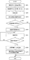
- FIG. 3 is a flowchart showing an outline of the work amount estimation process executed by the fingerprint registration device 10 according to the present embodiment. This process is executed, for example, when a new 10-finger fingerprint card image is input to the fingerprint registration device 10.
- step S101 the fingerprint image acquisition unit 101 acquires a 10-finger fingerprint card image of the person to be registered via the input device 157 or a network (not shown).
- FIG. 4 is a diagram showing an example of a 10-finger fingerprint card according to the present embodiment.
- the 10 fingers are the 10 fingers of both hands.
- the five fingers of one hand are called the thumb, index finger, middle finger, ring finger and little finger, respectively.
- the thumb, index finger, middle finger, ring finger and little finger are the thumb, index finger, middle finger, ring finger and little finger, respectively.
- the 10-finger fingerprint card contains a total of 14 types of fingerprint images, including 10 types of rolled fingerprints (RolledPrint) and 4 types of flat fingerprints (SlapPrint).
- the fingerprint image in the broken line portion RP is a rotating fingerprint.
- the fingerprint image in the broken line portion SP is a flat fingerprint.
- the fingerprint image shown in FIG. 4 can be, for example, an image of a pattern transferred to paper by applying ink or the like to a finger and pressing the finger on paper.
- the fingerprint image is stored in a storage unit or the like in a state of being digitized in a predetermined file format.
- the digitized fingerprint image can be, for example, a grayscale image.
- the fingerprint image may be an image collected by an optical fingerprint reading device or an image of a fingerprint left on an object, and the collection method is not particularly limited.
- 10 types of rotating fingerprint image frames and 4 types of flat fingerprint image frames are pre-printed.
- the rotating fingerprint image frame and the flat fingerprint image frame are used to extract the imprinted fingerprint area of each finger from the 10-finger fingerprint card.
- step S102 the fingerprint image acquisition unit 101 cuts out the rotation fingerprint image and the plane fingerprint image of the same finger from the rotation fingerprint image and the plane fingerprint image for 10 fingers recorded in the 10-finger fingerprint card image.
- step S103 the extraction unit 102 automatically extracts feature points and core wires from the rotating fingerprint image and the flat fingerprint image, respectively.
- the extraction unit 102 recognizes the black portion (the portion having low brightness) of the fingerprint image as shown in FIG. 4, and extracts the core wire by generating image data in which the core wire is drawn so as to trace the black portion.
- the extracted core wire may be, for example, a line having a width of one pixel.
- the algorithm used for extracting the core wire by the extraction unit 102 is not one, but may be various.
- the difference between the plurality of algorithms may be, for example, the difference in the parameters of image processing such as smoothing of the fingerprint image, contour enhancement, and noise removal performed as preprocessing at the time of extracting the core wire.
- the extraction unit 102 extracts the feature points of each core wire.
- feature points There are two types of feature points: a branch point where the core wire branches and an end point of the core wire.
- the extraction unit 102 extracts feature points and core wires from the rotating fingerprint and the plane fingerprint using the same algorithm.
- step S104 the extraction unit 102 collates the feature points extracted from the rotating fingerprint image and the plane fingerprint image, respectively.
- first feature points the feature points extracted from the rotating fingerprint
- second feature points the feature points extracted from the plane fingerprint
- FIG. 5A is an enlarged view showing an example of a rotating fingerprint image according to the present embodiment.
- two end points P11 and P12 are extracted with respect to the core wire.
- a branch point P13 and an end point P14 are extracted with respect to the core wire.
- three first feature points of a branch point P15, a branch point (confluence point) P16, and an end point P17 are extracted with respect to the core wire.
- FIG. 5B is an enlarged view showing an example of a flat fingerprint image according to the present embodiment.
- FIG. 5B shows a planar fingerprint with respect to the same finger common area as in FIG. 5A.
- the region R21 of FIG. 5B corresponds to the region R11 of FIG. 5A.
- the second feature point is not extracted in the region R21.
- the region R22 corresponds to the region R12 of FIG. 5A. Similar to the region R12, the branch point P23 and the end point P24 are extracted as the second feature points in the region R22. That is, the branch point P13 (first feature point) and the branch point P23 (second feature point) have a corresponding relationship. Similarly, the end point P14 (first feature point) and the end point P24 (second feature point) have a corresponding relationship.
- the area R23 corresponds to the area R13 of FIG. 5A. Unlike the region R13, only the end point P27 is extracted from the core wire in the region R23. That is, the end point P17 (first feature point) and the end point P27 (second feature point) have a corresponding relationship. However, the second feature point having a corresponding relationship with the first feature point of the branch point P15 or the confluence point P16 in FIG. 5A does not exist in the region R23. Further, the end point P18 (first feature point) and the end point P28 (second feature point) have a corresponding relationship.
- the feature points that do not have a correspondence with the second feature point of the flat fingerprint can be the target of the correction work of the user.
- the end points P11 and the end points P12 are deleted by replenishing the core wire connecting the end points P11 and the end points P12 with the plane fingerprint as a reference.
- the extraction unit 102 acquires the pair information and the movement amount of the first feature point and the second feature point.
- the pair information is information indicating that the first feature point and the second feature point have a corresponding relationship.
- the amount of movement is the amount of positional deviation between the first feature point and the second feature point that are in a corresponding relationship, and the imprinting of the rotating fingerprint and the flat fingerprint with reference to the positions of the first feature point and the second feature point in the image. It is used when overlapping areas.
- the extraction unit 102 identifies a common area and a non-common area in the two types of imprinted fingerprints.
- the common area is an imprint area that is common between the rotated fingerprint image and the flat fingerprint image.
- the non-common area is an imprint area excluding the common area from the imprint area included in the rotated fingerprint image.
- step S107 the extraction unit 102 specifies the number of unit blocks of the edit target area in the common area and the non-common area.
- step S108 the extraction unit 102 classifies the first feature points in the rotated fingerprint image into three patterns based on the region where the first feature points exist and the pair information.
- the extraction unit 102 classifies the first feature points as follows.
- a first feature point that exists in a common area with a flat fingerprint and has a corresponding relationship with a second feature point hereinafter referred to as "pairing feature point”
- B The first feature point that exists in the common area with the plane fingerprint and does not have a correspondence with the second feature point (hereinafter referred to as "non-pairing feature point”).
- C First feature point existing in the non-common area
- FIG. 6 is a diagram showing an example of feature points extracted from a rotating fingerprint image and a flat fingerprint image.
- the region A1 surrounded by the broken line is the imprinted region of the plane fingerprint.
- the region A2 surrounded by the alternate long and short dash line is the imprinted region of the rotating fingerprint.
- the area A1 is also a common area of the rotating fingerprint and the flat fingerprint.
- the region A3 excluding the common region (region A1) from the region A2 is a non-common region.
- the areas D1, D2 and D3 are unknown zones in which the first feature points are not extracted, that is, edit target areas.
- the circles in FIG. 6 indicate the first feature points which are the end points of the core wires.
- the square mark indicates a first feature point which is a branch point of the core wire.
- the direction of the line protruding like a whiskers from each of the first feature points represents the direction of the core wire.
- the first feature point represented by the white-painted circle mark or the square mark represents the pairing feature point having a corresponding relationship with the second feature point of the plane fingerprint.
- the first feature point represented by the black circle or square mark represents a non-pairing feature point that does not correspond to the second feature point of the flat fingerprint.
- feature points P1 and P2 are pairing feature points.
- Feature points P3, P4, P5, P6 are non-pairing feature points.
- step S109 the work amount estimation unit 103 calculates the estimated work amount in finger units, for example, based on the following calculation formula (1).
- W (B + C ⁇ B / (A + B)) ⁇ a + x ⁇ b ⁇ ⁇ ⁇ (1)
- W is the estimated amount of work.
- A is the total number of pairing feature points existing in the common area.
- B is the total number of non-pairing feature points existing in the common area.
- C is the total number of first feature points existing in the non-common region.
- x is the total number of edit target areas in which the first feature point is not extracted in the common area and the non-common area (that is, the entire imprinted area of the rotating fingerprint). The total number of edit target zones is counted with an image area of a predetermined size as one block.
- a and b are constants and can be set to desired values.
- the value of B / (A + B) has a correspondence relationship with the second feature point among the first feature points included in the common area of the rotating fingerprint and the plane fingerprint.
- the ratio occupied by the first feature point (non-pairing feature point) that does not exist is shown.
- the product of the ratio and the total number of first feature points existing in the non-common area estimates the detection accuracy of the first feature point in the non-common area based on the quality of the rotated fingerprint in the common area. Means that. Therefore, the larger the number of non-pairing, the larger the multiplication value. That is, since the detection accuracy of the first feature point is low, the amount of correction work in the non-common area increases. On the contrary, if the number of pairings is large, the multiplication value becomes small. That is, since the detection accuracy of the first feature point is high, the amount of correction work in the non-common area is reduced.
- step S110 the work amount estimation unit 103 determines whether or not the calculation for all fingers has been completed.
- step S110: YES the process proceeds to step S111.
- step S110 NO
- the process returns to step S102.
- the work amount estimation unit 103 calculates the estimated work amount for each card. For example, the work amount estimation unit 103 calculates the average value of the estimated work amount for 10 fingers for the common area and the non-common area in the common area and the non-common area based on the above calculation formula (1), and estimates the work amount in the card unit. Calculated as (total work amount).
- the work amount estimation unit 103 may calculate the estimated work amount by using the integrated value instead of the average value.
- step S112 the data processing unit 107 registers the estimated work amount in the database (for example, the storage unit 108) and ends the processing.
- the data processing unit 107 may register the estimated work amount in the database after normalizing it.
- the detection accuracy of the first feature point in the non-common area can be estimated based on the quality of the rotating fingerprint in the common area.
- the amount of work in the non-common area which occupies most of the total amount of work, can be easily estimated.
- the work amount estimation unit 103 is the total number (non-pairing number) of the first feature points having no correspondence with the second feature points in the common area. Estimate the amount of work based on.
- the first feature point that does not have a correspondence with the second feature point can be the target of the correction work.
- the work amount estimation unit 103 can calculate a more accurate estimated work amount by also considering the number of non-pairing.
- the second term of the calculation formula (1) is a part for estimating the amount of work in the correction work of the user for the editing target area. As the number of blocks in the editing target area increases, the amount of correction work increases. On the contrary, when the number of blocks in the editing target area is small, the amount of correction work is reduced.
- the amount of work in the common area and the non-common area can be easily estimated according to the size of the editing target area.
- FIG. 7 is a flowchart showing an outline of the search process executed by the fingerprint registration device 10 according to the present embodiment. This process is executed, for example, when a user performing a fingerprint registration operation selects a 10-finger fingerprint card to be worked.
- step S201 the display control unit 104 displays the search condition input screen on the display device 156.
- the user can refer to the search condition input screen and input the search condition using the input device 157.
- step S202 the input receiving unit 105 accepts the input of the search condition by the user.
- search conditions for example, it is preferable to be able to input a period, a user ID, a range of estimated work amount, whether or not a card is registered, and the like.
- step S203 when the search unit 106 executes the search process, the search unit 106 outputs the search result to the display control unit 104.
- step S204 the display control unit 104 displays the search result display screen created based on the search results on the display device 156.
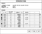
- FIG. 8A is a diagram showing an example of a search result display screen according to the present embodiment.
- the search condition specified by the user is displayed in the upper column of the screen.
- search conditions the creation date of the 10-finger fingerprint card (“November 01, 2020 to November 30, 2020”), the range of estimated work amount values (“40 or more”), and the DB registration status (“40 or more”). "Not specified") is described.
- the search results executed based on the search conditions are displayed in a list.
- the list includes card ID, estimated work amount, estimated work time, actual work time, DB registration status, and registrant ID as data items.
- the DB registration status indicates whether or not the 10-finger fingerprint card image is registered.
- the check box is displayed in a non-selectable state.
- the estimated work amount is normalized in the numerical range of 0 to 100.
- the user can select a card while comparing and examining the index value.
- the estimated work time obtained by converting the estimated work amount based on a predetermined conversion table is displayed.
- the user can intuitively grasp the working time, and it becomes easy to select a card.
- the data items on the search result display screen shown in FIG. 8A are only examples.
- data items may be displayed as shown in FIGS. 8B to 8D.
- the search result shown in FIG. 8B corresponds to the one obtained by excluding the two columns of the data items of the estimated work time and the actual work time from FIG. 8A.
- the search result shown in FIG. 8C corresponds to FIG. 8A excluding the two columns of the data items of the estimated work amount and the actual work time.
- the search result shown in FIG. 8D corresponds to the one obtained by removing one column of the data items of the actual working time from FIG. 8A.
- step S205 the input receiving unit 105 determines whether or not the work target has been specified on the search result display screen by the user operation.
- the process proceeds to step S206.
- step S205 NO
- the process ends.
- step S206 the display control unit 104 displays a registration work screen related to the designated 10-finger fingerprint card image.
- step S207 the user corrects the feature points and core wires in the rotated fingerprint image based on the plane fingerprint image of the same finger, and performs the registration work.
- step S208 the input receiving unit 105 determines whether or not the user has completed the registration work.
- step S208: YES the process proceeds to step S209.
- step S208 NO
- the process returns to step S207.
- step S209 the data processing unit 107 registers the fingerprint image corrected by the user and the work record data in the storage unit 108.
- step S210 the data processing unit 107 updates the correspondence between the estimated work amount and the estimated work time registered in the storage unit 108 based on the work record data, and ends the process.
- the fingerprint registration device 10 As described above, according to the fingerprint registration device 10 according to the present embodiment, the first feature point of the rotating fingerprint extracted from the 10-finger fingerprint card image input to the device is collated with the second feature point of the flat fingerprint. Based on the result, the work amount of the correction work of the user before the registration of the 10-finger fingerprint card image can be estimated, and the estimated work amount can be presented to the user. As a result, when the user manually corrects the 10-finger fingerprint card image, the user can grasp the amount of work before starting the work. That is, according to the present embodiment, there is provided a fingerprint registration device 10 that assists the user in correcting and registering a 10-finger fingerprint card image.
- the correspondence relationship between the estimated work amount and the estimated work time can be sequentially updated based on the actual work time (actual data). By accumulating actual data, it becomes possible to convert the estimated amount of work into time with high accuracy.
- the fingerprint registration device 10 described in the above-described embodiment can also be configured as in the following second to sixth embodiments.
- the code common to the code assigned in the figure of the first embodiment indicates the same object. The description of the parts common to the first embodiment will be omitted, and the different parts will be described in detail.
- the fingerprint registration device 10 according to the first embodiment described above has a configuration for displaying information that matches the search conditions when the user specifies the search conditions on the screen.
- the fingerprint registration device 10 according to the present embodiment is different from the first embodiment in that the user does not need to specify the search condition and perform the search process.
- the fingerprint registration device 10 is not registered for fingerprint verification from a database such as a storage unit 108 when a user requests registration work for a 10-finger fingerprint card image. Acquires the information of the finger fingerprint card and displays it in a list.
- FIG. 9 is a diagram showing an example of the estimation work information list screen according to the present embodiment.
- the estimated work information may be an estimated work amount normalized by a value of 0 to 100, or may be an estimated work time corresponding to the estimated work amount, as in the first embodiment.
- the user since the user does not have to specify the search condition, the user can work with a 10-finger fingerprint card and an estimation with fewer operations than in the case of the first embodiment. Can grasp work information.
- the fingerprint registration device 10 according to the first embodiment described above has a configuration in which the estimated work amount calculated for each finger is averaged and displayed as the total work amount for 10 fingers.
- the fingerprint registration device 10 according to the present embodiment is different from the first embodiment in that the estimated work amount calculated for each finger is displayed on the screen.
- FIG. 10 is a diagram showing an example of an estimated work amount list screen according to the present embodiment.
- the estimated work amount calculated for each of the left and right fingers is displayed for each card ID of the 10-finger fingerprint card.
- the estimated work amount of the little finger, ring finger, middle finger, index finger and thumb of the left hand is “3", "4", "2", “6", respectively. It is "7”. That is, in the left hand, the estimated work amount of the thumb is the largest value, and the estimated work amount of the middle finger is the smallest value.
- the estimated work amount of the thumb, index finger, middle finger, ring finger and little finger of the right hand is “10”, “1", “3”, “2" and "4", respectively. That is, in the right hand, the estimated work amount of the thumb is the largest value, and the estimated work amount of the index finger is the smallest value.
- the data items of the average value of the estimated work amount for each finger and the integrated value of the estimated work amount for each finger may be included in the list as the total work amount and displayed.
- the fingerprint registration device 10 since the user can grasp the estimated work amount calculated for each finger, it is possible to more easily select the card to be worked on from a large number of 10-finger fingerprint cards.
- the fingerprint registration device 10 is first in that the column of the rotating fingerprint included in the 10-finger fingerprint card image is color-coded and displayed so as to correspond to the range of the estimated work amount calculated for each finger. It is different from the embodiment.
- FIG. 11 is a diagram showing an example of an estimated work amount display screen according to the present embodiment.
- the range of estimated work amount calculated for each finger is divided into three classes C1, C2, and C3.
- Class C1 indicates that the estimated work amount is 0 to 33.
- Class C2 indicates that the estimated workload is 34-66.
- Class C3 indicates that the estimated workload is 67-100.
- the display colors of classes C1, C2, and C3 may be set to blue, yellow, and red, respectively.
- the type of display color and the number of display colors can be set arbitrarily.
- the user can intuitively grasp the estimated work amount calculated for each finger by the display color.
- the fingerprint registration device 10 according to the present embodiment is different from the first embodiment in that the estimated work amount calculated for each finger is superimposed and displayed in the column of the rotating fingerprint included in the 10-finger fingerprint card image. It's different.
- FIG. 12 is a diagram showing an example of an estimated work amount display screen according to the present embodiment. Here, it is shown that the estimated work amount calculated for each finger is superimposed and displayed in the column of the rotating fingerprint of 10 fingers.
- the user can grasp the value of the estimated work amount calculated for each finger together with the rotating fingerprint image. This allows the user to easily determine which finger has more or less work.
- FIG. 13 is a functional block diagram of the information processing apparatus 100 according to the present embodiment.
- the information processing apparatus 100 includes an acquisition unit 100A, an extraction unit 100B, and an estimation unit 100C.
- the acquisition unit 100A acquires a rotation fingerprint and a plane fingerprint related to the same finger.
- the extraction unit 100B extracts the first feature point from the rotating fingerprint and the second feature point from the plane fingerprint.
- the estimation unit 100C is based on the ratio of the first feature points that do not have a correspondence with the second feature point among the first feature points included in the common area of the rotary fingerprint and the flat fingerprint. The first amount of correction work performed by the user for the non-common area excluding the common area is estimated.
- an information processing device 100 that allows the user to easily grasp the amount of work during the fingerprint registration work.
- a processing method in which a program for operating the configuration of the embodiment is recorded in a storage medium so as to realize the functions of the above-described embodiment, the program recorded in the storage medium is read out as a code, and the program is executed in a computer is also described in each embodiment. Included in the category. That is, a computer-readable storage medium is also included in the scope of each embodiment. Further, not only the storage medium in which the above-mentioned program is recorded but also the program itself is included in each embodiment. Further, the one or more components included in the above-described embodiment may be a circuit such as an ASIC or FPGA configured to realize the function of each component.
- the storage medium for example, a floppy (registered trademark) disk, a hard disk, an optical disk, a magneto-optical disk, a CD (Compact Disk) -ROM, a magnetic tape, a non-volatile memory card, or a ROM can be used.
- the program recorded on the storage medium is not limited to the one that executes the processing by itself, but the one that operates on the OS (Operating System) and executes the processing in cooperation with other software and the function of the expansion board. Is also included in the category of each embodiment.
- SaaS Software as a Service
- An acquisition unit that acquires a rotating fingerprint and a flat fingerprint related to the same finger
- An extraction unit that extracts the first feature point from the rotating fingerprint and the second feature point from the plane fingerprint, respectively.
- the rotating fingerprint is based on the ratio of the first feature point having no correspondence with the second feature point among the first feature points included in the common area of the rotating fingerprint and the plane fingerprint.
- an estimation unit that estimates the first amount of correction work performed by the user for the non-common area excluding the common area, and Information processing device equipped with.
- the estimation unit estimates the third work amount of the correction work related to the common area based on the total number of the first feature points that do not have a correspondence relationship with the second feature point in the common area.
- the information processing device according to Appendix 2.
- the acquisition unit acquires the rotation fingerprint and the plane fingerprint from the fingerprint image group of 10 fingers related to the same person.
- the estimation unit estimates the total work amount in the correction work for the 10 fingers based on the first work amount, the second work amount, and the third work amount calculated for each finger.
- the estimation unit estimates the first work amount based on the product value of the total number of the first feature points included in the non-common region and the ratio.
- the information processing apparatus according to any one of Supplementary note 1 to 3.
- Appendix 6 A display control unit that displays an index value obtained by normalizing the total amount of work on the screen.
- Appendix 7 A display control unit that displays the estimated work time corresponding to the total work amount on the screen.
- Appendix 8 A processing unit that updates the estimated work time based on the actual data of the correction work corresponding to the total work amount.
- Fingerprint registration device 100 Information processing device 101 ... Fingerprint image acquisition unit 102 ... Extraction unit 103 ... Work amount estimation unit 104 ... Display control unit 105 ... Input reception unit 106 ... Search unit 107 ... Data processing unit 108 ... Storage unit 151 ... Processor 152 ... RAM 153 ... ROM 154 ... Storage 155 ... Communication I / F 156 ... Display device 157 ... Input device
Landscapes
- Engineering & Computer Science (AREA)
- Physics & Mathematics (AREA)
- General Physics & Mathematics (AREA)
- Theoretical Computer Science (AREA)
- Human Computer Interaction (AREA)
- Multimedia (AREA)
- Computer Vision & Pattern Recognition (AREA)
- Collating Specific Patterns (AREA)
Abstract
Description
しかしながら、上述のような補正作業における作業量は、ユーザが選択した10指指紋カードに記録されている指紋の状態によって大きく変動する。特に、回転指紋のうち、平面指紋と共通していない領域の作業量を推定することは困難であった。
本実施形態に係る指紋登録装置10について、図1乃至図8Dを参照しつつ説明する。本実施形態の指紋登録装置10は、指紋照合用に予め採取された指紋画像から照合の前処理として、指紋画像の登録及び補正作業を行うユーザの支援を行う。複数の指紋画像の間での特徴点を照合することにより、照合対象の指紋画像が同一人物のものであるか否かを判別する指紋照合を実行することが可能になる。
(A)平面指紋との共通領域内に存在し、かつ、第2特徴点との対応関係を有する第1特徴点(以下、「ペアリング特徴点」という。)
(B)平面指紋との共通領域内に存在し、かつ、第2特徴点との対応関係を有していない第1特徴点(以下、「非ペアリング特徴点」という。)
(C)非共通領域内に存在する第1特徴点
W=(B+C・B/(A+B))・a+x・b ・・・(1)
図7は、本実施形態に係る指紋登録装置10において実行される検索処理の概略を示すフローチャートである。この処理は、例えば指紋登録作業を行うユーザが作業対象の10指指紋カードを選択する場合に実行される。
上述した第1実施形態に係る指紋登録装置10は、ユーザが画面上で検索条件を指定した場合に、検索条件に合致する情報を表示する構成を備えていた。これに対し、本実施形態に係る指紋登録装置10は、ユーザによる検索条件の指定及び検索処理を必要としない点で第1実施形態とは異なっている。
上述した第1実施形態に係る指紋登録装置10は、指単位で算出された推定作業量を平均化し、10指分の全体作業量として表示する構成を備えていた。これに対し、本実施形態に係る指紋登録装置10は、指単位で算出された推定作業量を画面に表示する点で第1実施形態とは異なっている。
本実施形態に係る指紋登録装置10は、指単位で算出された推定作業量の範囲に対応するように、10指指紋カード画像に含まれる回転指紋の欄を色分けして表示する点で第1実施形態とは異なっている。
本実施形態に係る指紋登録装置10は、指単位で算出された推定作業量を、10指指紋カード画像に含まれる回転指紋の欄の中に重畳して表示する点で第1実施形態とは異なっている。
図13は、本実施形態に係る情報処理装置100の機能ブロック図である。情報処理装置100は、取得部100A、抽出部100B及び推定部100Cを備える。取得部100Aは、同じ指に係る回転指紋及び平面指紋を取得する。抽出部100Bは、回転指紋から第1特徴点、平面指紋から第2特徴点をそれぞれ抽出する。推定部100Cは、回転指紋と平面指紋との共通領域に含まれる第1特徴点のうち第2特徴点との対応関係を有していない第1特徴点が占める割合に基づいて、回転指紋のうち共通領域を除いた非共通領域に対してユーザが行う補正作業の第1作業量を推定する。
この開示は、上述の実施形態に限定されることなく、この開示の趣旨を逸脱しない範囲において適宜変更可能である。
同じ指に係る回転指紋及び平面指紋を取得する取得部と、
前記回転指紋から第1特徴点、前記平面指紋から第2特徴点をそれぞれ抽出する抽出部と、
前記回転指紋と前記平面指紋との共通領域に含まれる前記第1特徴点のうち前記第2特徴点との対応関係を有していない前記第1特徴点が占める割合に基づいて、前記回転指紋のうち前記共通領域を除いた非共通領域に対してユーザが行う補正作業の第1作業量を推定する推定部と、
を備える情報処理装置。
前記推定部は、前記第1特徴点及び前記第2特徴点の位置を基準として前記回転指紋及び前記平面指紋を重畳した場合において、前記回転指紋の中で前記第1特徴点が抽出されていない領域の大きさに基づいて前記領域に係る補正作業の第2作業量を推定する、
付記1に記載の情報処理装置。
前記推定部は、前記共通領域において前記第2特徴点との対応関係を有していない前記第1特徴点の総数に基づいて前記共通領域に係る補正作業の第3作業量を推定する、
付記2に記載の情報処理装置。
前記取得部は、同一人物に係る10指の指紋画像群から前記回転指紋及び前記平面指紋を取得し、
前記推定部は、各指について算出された前記第1作業量、前記第2作業量及び前記第3作業量に基づいて前記10指についての補正作業における全体作業量を推定する、
付記3に記載された情報処理装置。
前記推定部は、前記非共通領域に含まれる前記第1特徴点の総数と前記割合との乗算値に基づいて前記第1作業量を推定する、
付記1乃至3のいずれかに記載の情報処理装置。
前記全体作業量を正規化した指標値を画面に表示させる表示制御部、
を更に備える付記4に記載された情報処理装置。
前記全体作業量に対応する推定作業時間を画面に表示させる表示制御部、
を更に備える付記4に記載された情報処理装置。
前記全体作業量に対応する前記補正作業の実績データに基づいて前記推定作業時間を更新する処理部、
を更に備える付記7に記載の情報処理装置。
同じ指に係る回転指紋及び平面指紋を取得するステップと、
前記回転指紋から第1特徴点、前記平面指紋から第2特徴点をそれぞれ抽出するステップと、
前記回転指紋と前記平面指紋との共通領域に含まれる前記第1特徴点のうち前記第2特徴点との対応関係を有していない前記第1特徴点が占める割合に基づいて、前記回転指紋のうち前記共通領域を除いた非共通領域に対してユーザが行う補正作業の第1作業量を推定するステップと、
を備える情報処理方法。
コンピュータに、
同じ指に係る回転指紋及び平面指紋を取得するステップと、
前記回転指紋から第1特徴点、前記平面指紋から第2特徴点をそれぞれ抽出するステップと、
前記回転指紋と前記平面指紋との共通領域に含まれる前記第1特徴点のうち前記第2特徴点との対応関係を有していない前記第1特徴点が占める割合に基づいて、前記回転指紋のうち前記共通領域を除いた非共通領域に対してユーザが行う補正作業の第1作業量を推定するステップと、
を実行させるためのプログラムが記録された記録媒体。
100・・・情報処理装置
101・・・指紋画像取得部
102・・・抽出部
103・・・作業量推定部
104・・・表示制御部
105・・・入力受付部
106・・・検索部
107・・・データ処理部
108・・・記憶部
151・・・プロセッサ
152・・・RAM
153・・・ROM
154・・・ストレージ
155・・・通信I/F
156・・・表示装置
157・・・入力装置
Claims (10)
- 同じ指に係る回転指紋及び平面指紋を取得する取得部と、
前記回転指紋から第1特徴点、前記平面指紋から第2特徴点をそれぞれ抽出する抽出部と、
前記回転指紋と前記平面指紋との共通領域に含まれる前記第1特徴点のうち前記第2特徴点との対応関係を有していない前記第1特徴点が占める割合に基づいて、前記回転指紋のうち前記共通領域を除いた非共通領域に対してユーザが行う補正作業の第1作業量を推定する推定部と、
を備える情報処理装置。 - 前記推定部は、前記第1特徴点及び前記第2特徴点の位置を基準として前記回転指紋及び前記平面指紋を重畳した場合において、前記回転指紋の中で前記第1特徴点が抽出されていない領域の大きさに基づいて前記領域に係る補正作業の第2作業量を推定する、
請求項1に記載の情報処理装置。 - 前記推定部は、前記共通領域において前記第2特徴点との対応関係を有していない前記第1特徴点の総数に基づいて前記共通領域に係る補正作業の第3作業量を推定する、
請求項2に記載の情報処理装置。 - 前記取得部は、同一人物に係る10指の指紋画像群から前記回転指紋及び前記平面指紋を取得し、
前記推定部は、各指について算出された前記第1作業量、前記第2作業量及び前記第3作業量に基づいて前記10指についての補正作業における全体作業量を推定する、
請求項3に記載された情報処理装置。 - 前記推定部は、前記非共通領域に含まれる前記第1特徴点の総数と前記割合との乗算値に基づいて前記第1作業量を推定する、
請求項1乃至3のいずれか1項に記載の情報処理装置。 - 前記全体作業量を正規化した指標値を画面に表示させる表示制御部、
を更に備える請求項4に記載された情報処理装置。 - 前記全体作業量に対応する推定作業時間を画面に表示させる表示制御部、
を更に備える請求項4に記載された情報処理装置。 - 前記全体作業量に対応する前記補正作業の実績データに基づいて前記推定作業時間を更新する処理部、
を更に備える請求項7に記載の情報処理装置。 - 同じ指に係る回転指紋及び平面指紋を取得するステップと、
前記回転指紋から第1特徴点、前記平面指紋から第2特徴点をそれぞれ抽出するステップと、
前記回転指紋と前記平面指紋との共通領域に含まれる前記第1特徴点のうち前記第2特徴点との対応関係を有していない前記第1特徴点が占める割合に基づいて、前記回転指紋のうち前記共通領域を除いた非共通領域に対してユーザが行う補正作業の第1作業量を推定するステップと、
を備える情報処理方法。 - コンピュータに、
同じ指に係る回転指紋及び平面指紋を取得するステップと、
前記回転指紋から第1特徴点、前記平面指紋から第2特徴点をそれぞれ抽出するステップと、
前記回転指紋と前記平面指紋との共通領域に含まれる前記第1特徴点のうち前記第2特徴点との対応関係を有していない前記第1特徴点が占める割合に基づいて、前記回転指紋のうち前記共通領域を除いた非共通領域に対してユーザが行う補正作業の第1作業量を推定するステップと、
を実行させるためのプログラムが記録された記録媒体。
Priority Applications (2)
| Application Number | Priority Date | Filing Date | Title |
|---|---|---|---|
| JP2022569800A JP7441409B2 (ja) | 2020-12-14 | 2021-11-18 | 情報処理装置、情報処理方法及びプログラム |
| US18/265,289 US20240037983A1 (en) | 2020-12-14 | 2021-11-18 | Information processing device, information processing method, and storage medium |
Applications Claiming Priority (2)
| Application Number | Priority Date | Filing Date | Title |
|---|---|---|---|
| JP2020206529 | 2020-12-14 | ||
| JP2020-206529 | 2020-12-14 |
Publications (1)
| Publication Number | Publication Date |
|---|---|
| WO2022130891A1 true WO2022130891A1 (ja) | 2022-06-23 |
Family
ID=82058735
Family Applications (1)
| Application Number | Title | Priority Date | Filing Date |
|---|---|---|---|
| PCT/JP2021/042441 WO2022130891A1 (ja) | 2020-12-14 | 2021-11-18 | 情報処理装置、情報処理方法及び記録媒体 |
Country Status (3)
| Country | Link |
|---|---|
| US (1) | US20240037983A1 (ja) |
| JP (1) | JP7441409B2 (ja) |
| WO (1) | WO2022130891A1 (ja) |
Citations (4)
| Publication number | Priority date | Publication date | Assignee | Title |
|---|---|---|---|---|
| JP2007048116A (ja) * | 2005-08-11 | 2007-02-22 | Casio Comput Co Ltd | 画像読取装置及びその画像読取方法 |
| JP2012073704A (ja) * | 2010-09-28 | 2012-04-12 | Nec Engineering Ltd | 画像読取装置 |
| JP2019191913A (ja) * | 2018-04-25 | 2019-10-31 | 日本電気株式会社 | 情報処理システム、情報処理方法及びプログラム |
| JP2019207702A (ja) * | 2011-04-20 | 2019-12-05 | 日本電気株式会社 | 10指指紋カード入力装置、10指指紋カード入力方法、及び記憶媒体 |
-
2021
- 2021-11-18 JP JP2022569800A patent/JP7441409B2/ja active Active
- 2021-11-18 US US18/265,289 patent/US20240037983A1/en active Pending
- 2021-11-18 WO PCT/JP2021/042441 patent/WO2022130891A1/ja active Application Filing
Patent Citations (4)
| Publication number | Priority date | Publication date | Assignee | Title |
|---|---|---|---|---|
| JP2007048116A (ja) * | 2005-08-11 | 2007-02-22 | Casio Comput Co Ltd | 画像読取装置及びその画像読取方法 |
| JP2012073704A (ja) * | 2010-09-28 | 2012-04-12 | Nec Engineering Ltd | 画像読取装置 |
| JP2019207702A (ja) * | 2011-04-20 | 2019-12-05 | 日本電気株式会社 | 10指指紋カード入力装置、10指指紋カード入力方法、及び記憶媒体 |
| JP2019191913A (ja) * | 2018-04-25 | 2019-10-31 | 日本電気株式会社 | 情報処理システム、情報処理方法及びプログラム |
Also Published As
| Publication number | Publication date |
|---|---|
| US20240037983A1 (en) | 2024-02-01 |
| JP7441409B2 (ja) | 2024-03-01 |
| JPWO2022130891A1 (ja) | 2022-06-23 |
Similar Documents
| Publication | Publication Date | Title |
|---|---|---|
| JP5098504B2 (ja) | 文字認識プログラム、文字認識装置および文字認識方法 | |
| CN107203742B (zh) | 一种基于显著特征点提取的手势识别方法及装置 | |
| JPH05242165A (ja) | 画像データベースシステム | |
| JP3809305B2 (ja) | 画像検索装置及び画像検索方法及びコンピュータ読み取り可能な記憶媒体 | |
| CN105069431A (zh) | 人脸的定位方法和装置 | |
| JP7073886B2 (ja) | 情報処理システム、情報処理方法及びプログラム | |
| CN113449725A (zh) | 对象分类方法、装置、设备及存储介质 | |
| CN103886319A (zh) | 一种基于机器视觉的举牌智能识别方法 | |
| WO2022130891A1 (ja) | 情報処理装置、情報処理方法及び記録媒体 | |
| EP0665506B1 (en) | Method and apparatus for handwritten character recognition | |
| US11527102B2 (en) | Systems and methods of automated biometric identification reporting | |
| CN114255219B (zh) | 征象识别方法、装置、电子设备和存储介质 | |
| CN109190489A (zh) | 一种基于修复自动编码器残差的异常人脸检测方法 | |
| CN114972540A (zh) | 目标定位方法、装置、电子设备及存储介质 | |
| CN111382703B (zh) | 一种基于二次筛选与分数融合的指静脉识别方法 | |
| CN114820870A (zh) | 核电流程图辅助绘制方法、装置、计算机设备和存储介质 | |
| CN114677552A (zh) | 用于深度学习的指纹细节数据库标注方法和系统 | |
| JP3879810B2 (ja) | 読取支援装置 | |
| JPH0836510A (ja) | ユーザインタフェース評価装置 | |
| CN117392693B (zh) | 病理图像去笔迹的方法及设备 | |
| JP7381997B2 (ja) | 情報処理システム、情報処理方法及びプログラム | |
| WO2024024175A1 (ja) | 判定評価装置、方法、およびプログラム | |
| JP7336268B2 (ja) | 情報処理装置、情報処理方法及びプログラム | |
| CN111126121B (zh) | 人脸识别模型的调整方法、装置、设备及存储介质 | |
| CN114648765A (zh) | 基于卷积神经网络的顶面箱号识别方法、系统、存储介质及计算机设备 |
Legal Events
| Date | Code | Title | Description |
|---|---|---|---|
| 121 | Ep: the epo has been informed by wipo that ep was designated in this application |
Ref document number: 21906254 Country of ref document: EP Kind code of ref document: A1 |
|
| ENP | Entry into the national phase |
Ref document number: 2022569800 Country of ref document: JP Kind code of ref document: A |
|
| WWE | Wipo information: entry into national phase |
Ref document number: 18265289 Country of ref document: US |
|
| NENP | Non-entry into the national phase |
Ref country code: DE |
|
| 122 | Ep: pct application non-entry in european phase |
Ref document number: 21906254 Country of ref document: EP Kind code of ref document: A1 |