WO2022130866A1 - 配光制御システム及びセンシングシステム - Google Patents
配光制御システム及びセンシングシステム Download PDFInfo
- Publication number
- WO2022130866A1 WO2022130866A1 PCT/JP2021/041841 JP2021041841W WO2022130866A1 WO 2022130866 A1 WO2022130866 A1 WO 2022130866A1 JP 2021041841 W JP2021041841 W JP 2021041841W WO 2022130866 A1 WO2022130866 A1 WO 2022130866A1
- Authority
- WO
- WIPO (PCT)
- Prior art keywords
- light distribution
- distribution control
- vehicle
- information
- illuminance
- Prior art date
- Legal status (The legal status is an assumption and is not a legal conclusion. Google has not performed a legal analysis and makes no representation as to the accuracy of the status listed.)
- Ceased
Links
Images



Classifications
-
- B—PERFORMING OPERATIONS; TRANSPORTING
- B60—VEHICLES IN GENERAL
- B60Q—ARRANGEMENT OF SIGNALLING OR LIGHTING DEVICES, THE MOUNTING OR SUPPORTING THEREOF OR CIRCUITS THEREFOR, FOR VEHICLES IN GENERAL
- B60Q1/00—Arrangement of optical signalling or lighting devices, the mounting or supporting thereof or circuits therefor
- B60Q1/02—Arrangement of optical signalling or lighting devices, the mounting or supporting thereof or circuits therefor the devices being primarily intended to illuminate the way ahead or to illuminate other areas of way or environments
- B60Q1/04—Arrangement of optical signalling or lighting devices, the mounting or supporting thereof or circuits therefor the devices being primarily intended to illuminate the way ahead or to illuminate other areas of way or environments the devices being headlights
- B60Q1/14—Arrangement of optical signalling or lighting devices, the mounting or supporting thereof or circuits therefor the devices being primarily intended to illuminate the way ahead or to illuminate other areas of way or environments the devices being headlights having dimming means
- B60Q1/1415—Dimming circuits
- B60Q1/1423—Automatic dimming circuits, i.e. switching between high beam and low beam due to change of ambient light or light level in road traffic
- B60Q1/143—Automatic dimming circuits, i.e. switching between high beam and low beam due to change of ambient light or light level in road traffic combined with another condition, e.g. using vehicle recognition from camera images or activation of wipers
-
- B—PERFORMING OPERATIONS; TRANSPORTING
- B60—VEHICLES IN GENERAL
- B60Q—ARRANGEMENT OF SIGNALLING OR LIGHTING DEVICES, THE MOUNTING OR SUPPORTING THEREOF OR CIRCUITS THEREFOR, FOR VEHICLES IN GENERAL
- B60Q9/00—Arrangement or adaptation of signal devices not provided for in one of main groups B60Q1/00 - B60Q7/00, e.g. haptic signalling
-
- B—PERFORMING OPERATIONS; TRANSPORTING
- B60—VEHICLES IN GENERAL
- B60Q—ARRANGEMENT OF SIGNALLING OR LIGHTING DEVICES, THE MOUNTING OR SUPPORTING THEREOF OR CIRCUITS THEREFOR, FOR VEHICLES IN GENERAL
- B60Q2300/00—Indexing codes for automatically adjustable headlamps or automatically dimmable headlamps
- B60Q2300/30—Indexing codes relating to the vehicle environment
- B60Q2300/31—Atmospheric conditions
- B60Q2300/314—Ambient light
-
- B—PERFORMING OPERATIONS; TRANSPORTING
- B60—VEHICLES IN GENERAL
- B60Q—ARRANGEMENT OF SIGNALLING OR LIGHTING DEVICES, THE MOUNTING OR SUPPORTING THEREOF OR CIRCUITS THEREFOR, FOR VEHICLES IN GENERAL
- B60Q2300/00—Indexing codes for automatically adjustable headlamps or automatically dimmable headlamps
- B60Q2300/30—Indexing codes relating to the vehicle environment
- B60Q2300/32—Road surface or travel path
-
- B—PERFORMING OPERATIONS; TRANSPORTING
- B60—VEHICLES IN GENERAL
- B60Q—ARRANGEMENT OF SIGNALLING OR LIGHTING DEVICES, THE MOUNTING OR SUPPORTING THEREOF OR CIRCUITS THEREFOR, FOR VEHICLES IN GENERAL
- B60Q2300/00—Indexing codes for automatically adjustable headlamps or automatically dimmable headlamps
- B60Q2300/40—Indexing codes relating to other road users or special conditions
- B60Q2300/41—Indexing codes relating to other road users or special conditions preceding vehicle
-
- B—PERFORMING OPERATIONS; TRANSPORTING
- B60—VEHICLES IN GENERAL
- B60Q—ARRANGEMENT OF SIGNALLING OR LIGHTING DEVICES, THE MOUNTING OR SUPPORTING THEREOF OR CIRCUITS THEREFOR, FOR VEHICLES IN GENERAL
- B60Q2300/00—Indexing codes for automatically adjustable headlamps or automatically dimmable headlamps
- B60Q2300/40—Indexing codes relating to other road users or special conditions
- B60Q2300/42—Indexing codes relating to other road users or special conditions oncoming vehicle
-
- B—PERFORMING OPERATIONS; TRANSPORTING
- B60—VEHICLES IN GENERAL
- B60Q—ARRANGEMENT OF SIGNALLING OR LIGHTING DEVICES, THE MOUNTING OR SUPPORTING THEREOF OR CIRCUITS THEREFOR, FOR VEHICLES IN GENERAL
- B60Q2300/00—Indexing codes for automatically adjustable headlamps or automatically dimmable headlamps
- B60Q2300/40—Indexing codes relating to other road users or special conditions
- B60Q2300/45—Special conditions, e.g. pedestrians, road signs or potential dangers
Definitions
- the present invention relates to a light distribution control system that controls the light distribution of the headlights of the vehicle, including a sensing system that recognizes the outside world of the vehicle, and the sensing system thereof.
- the pedestrian In order for the driver of a car to recognize a pedestrian, it is necessary for the pedestrian to be illuminated by the light of a street light or headlight, and the light of the headlight is especially important on a road with few street lights.
- ADB Adaptive Driving Beam
- the image captured by the camera is divided into multiple blocks, and the change in brightness is estimated for each block. Then, there is a method of determining the light distribution control condition from the estimated change in brightness and performing the light distribution control.
- the brightness of the upper limit of the illuminating illumination that becomes acceptable glare based on the relative distance between the own vehicle and the object.
- the driver performs light distribution control in a control mode specified in a pre-designated area to drive the driver on a busy road or a dark road. There is a method to control according to the wishes of the hand.
- Headlights are important for drivers to recognize pedestrians at night, but on dark roads where high beams are needed, if the driver forgets to switch to high beams, or if the driver forgets to switch to high beams, or if the driver has AHB or ADB. Even if the light control function is installed, it may be forgotten to enable the light distribution control function.
- Patent Document 1 if the driver specifies in advance an area for which light distribution control is desired, appropriate light distribution control can be performed, but it is not effective on a road or the like for the first time.
- the present invention has been made in view of the above circumstances, and an object thereof is to improve the recognition performance of an object such as a pedestrian by performing appropriate light distribution control even on a road passing for the first time. It is an object of the present invention to provide a light distribution control system that can be used, and a sensing system that can be suitably used for the light distribution control system.
- the light distribution control system of the present invention includes a sensing system that recognizes the outside world of the vehicle, and is a light distribution control system that controls the light distribution of the headlights of the vehicle, and is a light distribution control system around the vehicle.
- An illuminance acquisition unit that acquires illuminance information
- an object recognition unit that recognizes the distance from the vehicle to an object on the traveling path of the vehicle
- a position information acquisition unit that acquires the position information of the vehicle, and the vehicle.
- the writing device for writing the light distribution control area information for determining the area where the light distribution control is required based on the illuminance and the distance, or the illuminance and the distance, together with the position information of the Based on the read device that reads the light distribution control area information corresponding to the position information of the vehicle and the read light distribution control area information, the light distribution control of the headlight is performed, or via a notification device. It is characterized by comprising a light distribution control unit for notifying the driver of the vehicle of the recommendation of switching the high beam of the headlight.
- the light distribution control system of the present invention is a light distribution control system that controls the light distribution of the headlights of the vehicle, and has an illuminance acquisition unit that acquires information on the illuminance around the vehicle and position information of the vehicle.
- a reading device that reads out the light distribution control area information corresponding to the position information of the vehicle from the position information acquisition unit for acquiring the light distribution and the database device in which the light distribution control area information for determining the area requiring light distribution control is written.
- the light distribution control of the headlight is performed based on the read light distribution control area information, or the driver of the vehicle is notified of the recommendation of switching the high beam of the headlight via the notification device. It is characterized by including a light distribution control unit.
- the sensing system of the present invention is a sensing system that recognizes the outside world of a vehicle in order to control the light distribution of the headlight of the vehicle, and has an illuminance acquisition unit that acquires information on the illuminance around the vehicle.
- the object recognition unit that recognizes the distance from the vehicle to the object on the traveling path of the vehicle, the position information acquisition unit that acquires the position information of the vehicle, the position information of the vehicle, and the illuminance and the distance.
- it is characterized by comprising a writing device for writing the light distribution control area information in which the area for which light distribution control is required is determined based on the illuminance and the distance to the database device.
- the present invention in high beam switching, by accumulating data after determining whether the high beam is an area necessary for danger prevention (an area where there is a risk of collision with an object and light distribution control is necessary). It is possible to store useful information on the server.
- the information on the area necessary for high beam to prevent danger is acquired from the server, and if the area is on the course, the driver is notified of the recommendation to switch the high beam, and the light distribution can be controlled. It is possible to alert the driver even if the vehicle is not equipped with various headlights.
- FIG. 2 is a schematic flow chart of data at the time of data transmission in FIG.
- FIG. 6 is a schematic flow chart of data in an embodiment different from FIG. 6 in FIG.
- FIG. 2 is a schematic flow chart of data at the time of data reception in FIG.
- Example 1 A light distribution control system including the sensing system according to the first embodiment of the present invention will be described with reference to FIGS. 1 to 10.
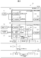
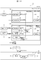
- FIG. 1 is a schematic configuration diagram of the entire system of the control system 1 including the light distribution control system including the sensing system according to the first embodiment and the database device.
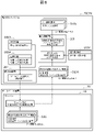
- FIG. 2 shows a detailed configuration diagram of the entire system of the control system 1 according to the first embodiment.
- the control system 1 of the present embodiment shown in FIGS. 1 and 2 includes a sensing system that recognizes the outside world of the vehicle, and is divided into a light distribution control system 10 that controls the light distribution of the headlights of the vehicle and a database device 30.
- the light distribution control system 10 including this sensing system and the database device 30 can communicate with each other via the network 20.
- the light distribution control system 10 of this embodiment is provided in the vehicle 1A, and the external sensor 11 for acquiring information (sensor information) in front of or around the vehicle 1A and the obstacle 5 (obstacle 5) from the information acquired by the external sensor 11.
- a recognition processing device 100 that recognizes objects that can be obstacles, including moving objects such as pedestrians, bicycles, and cars, and light spots (including vehicle headlights, tail lamps, street lights 6, etc.), and a vehicle 1A.
- the illuminance sensor 12 that acquires the illuminance information around the vehicle, the position information sensor 13 that acquires the position information of the vehicle 1A, and the light distribution control information are created to control the headlight 14 of the vehicle 1A, or the vehicle 1A.
- a light distribution processing device 200 for notifying the driver of the recommendation of switching the headlight 14 to the high beam by the notification device 15 is provided.
- the light distribution processing device 200 is provided with a communication unit 206 that communicates with the database device 30 via the network 20.
- the database device 30 of this embodiment is installed outside the vehicle 1A, and communicates with the light distribution control system 10 (communication unit 206 of the light distribution processing device 200) via the network 20 with the communication unit 31.
- a server 32 for writing or writing data transmitted / received by the communication unit 31 is provided (particularly, see FIG. 2).
- the outside world sensor 11 is a sensor that is installed in front of the vehicle 1A or the like and acquires information (sensor information) in front of or around the vehicle 1A.
- the outside world sensor 11 acquires three-dimensional information of a stereo camera, a monocular camera, a millimeter-wave radar that can acquire the distance and angle of an object, and an object that can capture images in front of and around the vehicle 1A.
- the illuminance sensor 12 is a sensor capable of acquiring illuminance information around the vehicle 1A mounted on the dashboard of the vehicle 1A, a front window, or the like.
- the position information sensor 13 is a GPS receiver that receives position information from a vehicle 1A or a GPS (Global Positioning System) satellite installed in a navigation system installed in the vehicle 1A, or an external sensor such as a stereo camera or LiDAR.
- a method of acquiring position information by executing an algorithm for estimating a position on 3D map data stored in the storage device 202 of the light distribution processing device 200 from the 3D information around the vehicle 1A that can be acquired in 11. It may be the one that uses.
- the headlight 14 is installed in front of the vehicle 1A, and is a headlight capable of switching between a high beam and a low beam based on the output result of the light distribution processing device 200, and an actuator (for example) that changes the optical axis of a plurality of headlights.
- An actuator for example
- Multiple motors) and a shade mechanism for blocking a part of the light of each headlight are provided, and a headlight that can change the irradiation direction and irradiation range of the headlight can be used.
- the notification device 15 is installed in the vehicle 1A and notifies the driver of the recommendation of switching the high beam of the headlight 14 based on the output result of the light distribution processing device 200.
- the recommendation of high beam switching may be notified to the instrument panel by characters, symbols, images, animations, etc., or by voice.
- the recognition processing device 100 and the light distribution processing device 200 are computers, respectively, and as shown in FIG. 2, for example, an input unit, central processing units 101 and 201 (CPU or MPU) which are processors, and a storage device 102. It has a read-only memory (ROM) and a random access memory (RAM), which are 202, and an output unit, respectively. Of these, the input unit converts various information input to the recognition processing device 100 and the light distribution processing device 200 so that the CPU can calculate.
- CPU central processing units 101 and 201
- RAM random access memory
- the ROM is a recording medium in which a control program for executing arithmetic processing described later and various information necessary for executing the arithmetic processing are stored, and the CPU has an input unit and a ROM according to the control program stored in the ROM. , Performs predetermined arithmetic processing on the signal taken from the RAM. From the output unit, commands for controlling the output target, information used by the output target, and the like are output.
- the storage devices 102 and 202 are not limited to the above-mentioned semiconductor memories such as ROM and RAM, and can be replaced with magnetic storage devices such as hard disk drives, for example.
- the central processing unit 101 of the recognition processing device 100 includes an obstacle recognition unit (object recognition unit) 103 and a light spot identification unit 104 as arithmetic processing blocks.
- the obstacle recognition unit 103 of the recognition processing device 100 recognizes an obstacle 5 (FIG. 1) in front of or around the vehicle 1A from the information acquired by the outside world sensor 11.
- an obstacle 5 FOG. 1
- a method of recognizing an obstacle in front of or around the vehicle 1A as a three-dimensional object by using three-dimensional information acquired by a stereo camera, LiDAR, or the like is used.
- Boost learn features such as edges and colors from images that are recognized or non-recognized in advance, and learn discriminators such as SVM (Support Vector Machine) and Ada Boost. It is performed and the features such as edges and colors are calculated from the images taken when using it, and it is identified by a trained classifier, or CNN (Convolutional Neural Network) etc. from the images to be recognized or not recognized in advance.
- a method of recognizing a recognition target is used by learning a network for identification and identifying it with the learned network when using it.
- the obstacle recognition unit 103 calculates and recognizes the recognized distance 4 (FIG. 1) to the obstacle, and the recognition information is sent to the light distribution control unit 205 of the light distribution processing device 200.
- the light spot identification unit 104 of the recognition processing device 100 recognizes the light spots in front of or around the vehicle 1A from the information acquired by the outside world sensor 11. For example, a pixel whose brightness is equal to or higher than a certain value is detected from an image taken by a stereo camera or a monocular camera, and adjacent regions are integrated to obtain a light spot region. Further, using the luminance information of the light spot, the relative distance from the vehicle 1A, the information of the relative position from the vehicle 1A, etc., the light spot of the headlight or the tail lamp of the vehicle or other light spots (for example, the street light 6 (for example, street light 6) By identifying whether it is FIG. 1)), the type of light spot is identified.
- vehicle headlights and tail lamps can be used. It is also possible to use a method of identifying whether the light spot is a light spot or another light spot.
- the light spot identification information (type of light spot) of the light spot identification unit 104 is sent to the light distribution control unit 205 of the light distribution processing device 200.
- the central processing unit 201 of the light distribution processing device 200 includes an illuminance acquisition unit 203, a position information acquisition unit 204, and a light distribution control unit 205 as arithmetic processing blocks.
- the illuminance acquisition unit 203 of the light distribution processing device 200 acquires illuminance information around the vehicle 1A from the illuminance sensor 12 mounted on the vehicle 1A.
- the acquired illuminance information is sent to the light distribution control unit 205.
- the position information acquisition unit 204 of the light distribution processing device 200 acquires the position information of the vehicle 1A from the position information sensor 13. The acquired position information is sent to the light distribution control unit 205.
- the area where the light distribution control of the headlight 14 is necessary for danger prevention (the area 7 where there is a risk of collision with an obstacle and the light distribution control is necessary (FIG. 1)). Whether or not it is classified for each scene from the information on the distance to the obstacle recognized by the obstacle recognition unit 103 of the recognition processing device 100 and the illuminance information around the vehicle 1A acquired by the illuminance acquisition unit 203. Then, together with the position information acquired by the position information acquisition unit 204, the area information (area information for determining an area where there is a risk of collision with an obstacle and light distribution control is required) is obtained from the communication unit 206 via the network 20.
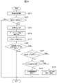
- FIG. 3 shows a flowchart (in other words, a flowchart at the time of data storage in the light distribution control unit 205) for determining whether or not the light distribution control of the headlight 14 is an area necessary for risk prevention in the light distribution control system 10. It was shown to.
- the recognition processing device 100 and the light distribution processing device 200 of the light distribution control system 10 repeatedly execute the flowchart of FIG. 3 in a predetermined control cycle.
- step S101 the recognition processing device 100 and the light distribution processing device 200 acquire sensor information from the outside world sensor 11, the illuminance sensor 12, and the position information sensor 13.
- step S102 day / night determination is performed from the sensor information acquired from the sensor (for example, using information such as illuminance and image brightness), and the processing after step S104 is executed only when it is determined to be night in step S103. ..
- step S104 the obstacle recognition unit 103 of the recognition processing device 100 recognizes an obstacle in front of or around the vehicle 1A (specifically, an obstacle on the traveling path of the vehicle 1A), and in step S105, recognition is performed in step S104.
- step S107 The processing after step S107 is executed only when it is determined in step S106 that there is a risk of collision with an obstacle. As a result, it is possible to determine in the subsequent steps whether or not the high beam is an area necessary for danger prevention only in the area where there is a risk of collision with an obstacle, and upload the information to the server 32 of the database device 30.
- the illuminance acquisition unit 203 of the light distribution processing device 200 acquires illuminance information around the vehicle 1A from the illuminance sensor 12.
- step S107 when the illuminance acquired in step S107 is less than the threshold value in step S108, and the distance to the obstacle identified in step S104 in step S109 (at the recognition start distance). Therefore, when the distance from the vehicle to the obstacle at the time when the obstacle recognition unit 103 first recognizes the obstacle) is less than the threshold value, it is determined in step S110 that the scene (area) requires a high beam for danger prevention. ..
- step S111 it is determined that the area has a risk of collision, and it is recommended to travel with a high beam while traveling because the surrounding area is bright or an obstacle can be recognized even in a distant place.
- the illuminance acquired by the illuminance acquisition unit 203 and the distance from the vehicle to the obstacle at the time when the obstacle recognition unit 103 first recognizes the obstacle are used. . It is determined whether or not to write the light distribution control area information for determining the area where the light distribution control is required to the database device 30.
- FIG. 6 shows data when the light distribution control unit 205 of the light distribution processing device 200 determines whether the light distribution control of the headlight 14 is an area necessary for risk prevention and transmits data to the server 32 of the database device 30.
- the flow chart of is described.
- the light distribution control unit 205 needs to control the light distribution of the headlight 14 to prevent danger.
- the result of determining whether or not the area is a certain area is stored in the determination result of D205.
- the position information D204 acquired by the position information acquisition unit 204 is stored in the position information of the D205, transmitted to the database device 30 via the network 20, and stored as data D32 in the server 32 of the database device 30.
- the determination as to whether or not the light distribution control of the headlight 14 performed by the light distribution control system 10 is a scene necessary for danger prevention may be performed outside the vehicle 1A other than the light distribution control system 10.
- it may be carried out on the server 32 of the database device 30.
- the area where there is a risk of collision with the obstacle is determined from the position information, the information of the distance to the obstacle, and the information of the illuminance on the vehicle 1A side, and the area information where there is a risk of collision with the obstacle.
- the position information, the distance information to the obstacle, and the illuminance information are written to the server 32 of the database device 30, and the position written on the server 32 side of the database device 30.
- There is also a method of determining and storing an area where there is a risk of collision with an obstacle from information, information on the distance to an obstacle, and information on illuminance.
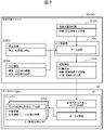
- FIG. 7 shows a data flow diagram when the server 32 of the database device 30 determines whether or not the light distribution control of the headlight 14 is a scene necessary for danger prevention.
- the location information D204 is defined as the transmission information D205, and is transmitted to the database device 30 via the network 20 to determine whether the light distribution control of the headlight 14 is an area necessary for danger prevention in the server 32 of the database device 30. And accumulate data as D32.
- the server 32 of the database device 30 provided outside the vehicle 1A determines the area requiring light distribution control based on the information on the distance to the obstacle and the information on the illuminance written together with the position information. It functions as an arithmetic unit that creates light distribution control area information.
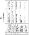
- the information of the light spot recognized by the light spot identification unit 104 in addition to the information of the illuminance measured in step S107, for example, there are many vehicles and many street lights 6 (FIG. 1), probably because it is a bright scene. It is also possible to determine whether the scene is bright, and the scenes can be further classified as shown in Tables Nos. 4 and 5 of the conditions and control contents for each scene in FIG.
- the illuminance threshold 3 [lx] is the standard for residential areas on roads with low traffic, and 5 [lx] is the standard for roads with heavy traffic, according to the standard for road lighting for pedestrians (JIS Z9111-1988).
- the illuminance 5 [lx] can be used as the illuminance threshold in step S108 of FIG.
- the headlight (low beam) has the ability to check traffic obstacles at a distance of 40 [m], and the low beam illuminates obstacles at a distance of up to 40 [m]. Can be done. Therefore, when the distance at which the obstacle is started to be recognized (recognition start distance) is 40 [m] or less, the high beam is required to recognize the obstacle from a distance. Therefore, for example, 40 [m] is used as the threshold value of the distance in step S109 in FIG. However, the threshold value of the distance can be changed depending on the performance of the low beam of the headlight, and may be a threshold value other than 40 [m].
- the information actually determined in steps S110 and S111 and stored in the server 32 of the database device 30 is acquired from the database device 30 by the light distribution control system 10 via the network 20, and the light distribution control system 10
- the flow used for the light distribution control of the headlight 14 in the light distribution control unit 205 of the light distribution processing device 200 will be described.
- the information stored in the server 32 of the database device 30 via the network 20 in the light distribution control system 10 provided in the vehicle 1A is transferred to the network 20 in the light distribution control system 10 provided in the vehicle 1A.
- a vehicle that acquires data from the database device 30 via the database device 30, that is, a vehicle that stores data in the database device 30 and a vehicle that acquires data from the database device 30 are described as the same vehicle, but a vehicle that stores data in the database device 30. It goes without saying that the vehicle may be different from the vehicle that acquires data from the database device 30.
- the light distribution control unit 205 of the light distribution processing device 200 of the light distribution control system 10 For example, the control as shown in FIG. 5 is performed.
- step S110 of FIG. 3 since the illuminance is less than the threshold value and the recognition start distance of the obstacle is less than the threshold value, the low beam of the headlight 14 may collide with an obstacle such as a pedestrian, and the high beam is reached. It can be judged that switching is a necessary scene for risk prevention. Therefore, the control is equipped with headlights that can automatically enable the light distribution control function, notify (alarm) the driver of the recommendation to switch to high beam, and change the irradiation direction and range of the headlights. If this is the case, the light distribution control that emphasizes the vicinity is performed by controlling the direction of the headlights that emphasizes the vicinity and widens horizontally (Table No. 1 in FIG. 5).
- step S111 of FIG. 3 since the illuminance is equal to or greater than the threshold value and the obstacle recognition start distance is equal to or greater than the threshold value, there is a risk of collision with an obstacle such as a pedestrian, but the scene in which the obstacle is easily recognized. Therefore, by notifying (alarming) the driver of the recommendation to switch to the high beam, the driver is notified that there is an area on the road where there is a risk of collision with an obstacle, and the driver is alerted (Fig. 5). Table No. 2).
- the position information acquired by the position information acquisition unit 204 is transmitted from the communication unit 206 to the database device 30 via the network 20, and the database device 30 is used. Based on the location information (described later), the area information stored in the server 32 where there is a risk of collision with an obstacle is read from. Area information at risk of collision with an obstacle transmitted from the communication unit 31 via the network 20 is received by the communication unit 206 of the light distribution processing device 200, and the light distribution control information is transmitted by the light distribution control unit 205. It is created and the light distribution of the headlight 14 of the vehicle 1A is controlled, or the notification device 15 notifies the driver of the vehicle 1A of the recommendation of high beam switching.
- the light distribution control unit 205 and the communication unit 206 of the light distribution processing device 200 determine from the database device 32 (the server 32 of the server 32) the area where the light distribution control corresponding to the position information of the vehicle 1A is required ( It functions as a read device that reads (acquires) the light distribution control area information that has been classified).
- the light distribution control system 10 acquires area information at risk of collision with an obstacle from the database device 30, controls the headlight 14, or notifies the driver of the recommendation of high beam switching by the notification device 15. (In other words, the flowchart at the time of data acquisition in the light distribution control unit 205) is shown.
- the light distribution processing device 200 of the light distribution control system 10 repeatedly executes the flowchart of FIG. 4 in a predetermined control cycle.
- step S201 the illuminance acquisition unit 203 acquires the illuminance information from the illuminance sensor 12.
- step S202 when the illuminance acquired in step S201 is less than the threshold value, the processes after step S203 are performed.
- step S203 the position information acquisition unit 204 acquires position information from the position information sensor 13.
- step S204 the location information acquired in step S203 is transmitted from the communication unit 206 to the database device 30 via the network 20, and is stored in the server 32 from the database device 30 based on the location information (described later). Read out area information where there is a risk of collision with an obstacle.
- Step S205 Area information at risk of collision with an obstacle transmitted from the communication unit 31 via the network 20 is received by the communication unit 206 of the light distribution processing device 200, and is received by the light distribution control unit 205 with the received obstacle. Get information on areas where there is a risk of collision.
- step S205 for example, the travel path information of the own vehicle is acquired by estimating the travel path information of the own vehicle from the position information or acquiring the route information of the own vehicle from the navigation system.
- step S206 it is determined whether or not the area information at risk of collision with the obstacle acquired in step S204 exists on the traveling path of the own vehicle acquired in step S205, and the obstacle is found on the traveling path of the own vehicle. Only when there is area information in which there is a risk of collision, the processing after step S207 is performed.
- the distance from the vehicle to the obstacle at the time when the obstacle recognition unit 103 first recognizes the obstacle is used. Therefore, it may be determined whether or not to read the light distribution control area information for which the area for which light distribution control is required is determined from the database device 30.
- step S207 when the high beam of the headlight 14 is a scene necessary for danger prevention, the processing after step S208 is performed as the area information in which there is a risk of collision with the obstacle acquired in step S204.
- step S208 when the vehicle is equipped with a light distribution control function such as AHB or ADB, the processes after step S209 are performed.
- step S209 the light distribution control function such as AHB or ADB is enabled.
- step S210 in the case of a scene other than the scene where the high beam of the headlight 14 is necessary for danger prevention in step S207 and the vehicle in which the light distribution control function is not installed in step S208, the notification device 15 informs the driver of the vehicle. Notify the recommendation of high beam switching of the headlight 14.
- FIG. 8 shows a flow chart of data from the database device 30 until the light distribution control unit 205 of the light distribution processing device 200 acquires the data and implements the light distribution control.
- the illuminance information D203 acquired by the illuminance acquisition unit 203 is less than the threshold value
- the position information D204 acquired by the position information acquisition unit 204 is used and information (with an obstacle) is transmitted from the database device 30.
- Acquire area information that determines the area where there is a risk of collision and light distribution control is required.
- the database device 30 acquires area information around the position information D204 around the position information D204 from the communication unit 31 via the network 20 via the network 20 after acquiring area information in the range of a certain threshold value as shown by reference numeral 9 in FIGS. Data is transmitted to the light distribution processing device 200.
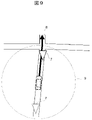
- the own vehicle In the light distribution control unit 205 of the light distribution processing device 200, as shown in FIG. 9, based on the area information D205 at risk of collision received by the communication unit 206 and the travel path information D207 of the own vehicle, the own vehicle When there is an area (information) 7 on the course 8 where there is a risk of collision, the light distribution control function is enabled and the notification of high beam switching recommendation is implemented.
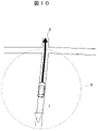
- the light distribution control function As shown in FIG. 10, if there is no area (information) 7 at risk of collision on the traveling path 8 of the own vehicle, the light distribution control function is not enabled and the notification of high beam switching recommendation is not performed. You can also do it. Further, at this time, the light spot identification information D 104 acquired by the light spot identification unit 104 can also be used.
- the light distribution control area information for determining the area requiring light distribution control corresponding to the position information of the vehicle 1A is read from the database device 32 (server 32), and the vehicle 1A progresses. After determining whether or not it exists on the road, control corresponding to the light distribution control area information that determines the area for which light distribution control is required is performed.
- the light distribution control system 10 of the first embodiment is a light distribution control system that includes a sensing system that recognizes the outside world of the vehicle and controls the light distribution of the headlights of the vehicle.
- the illuminance acquisition unit 203 that acquires information on the illuminance around the vehicle, the obstacle recognition unit (object recognition unit) 103 that recognizes the distance from the vehicle to the object on the traveling path of the vehicle, and the position information of the vehicle.
- a database of light distribution control area information for determining an area requiring light distribution control based on the illuminance and the distance, or the illuminance and the distance, together with the position information acquisition unit 204 for acquiring the light distribution and the position information of the vehicle.
- the head is based on a writing device for writing to the device 30, a reading device for reading the light distribution control area information corresponding to the position information of the vehicle from the database device 30, and the read light distribution control area information. It is provided with a light distribution control unit 205 that controls the light distribution of the light or notifies the driver of the vehicle of the recommendation of switching the high beam of the headlight via the notification device.
- the information on the distance from the vehicle to the obstacle and the information on the area where there is a risk of collision with the obstacle determined whether or not the high beam is necessary for danger prevention from the information on the illuminance around the vehicle are written in the database device 30.
- the user side reads out the area information that corresponds to the position information of the vehicle and has a risk of collision with obstacles, and based on the area information that has a risk of collision with obstacles, the high beam is necessary for danger prevention.
- the high beam is accumulated by determining whether the high beam is an area necessary for danger prevention (an area where there is a risk of collision with an object and light distribution control is necessary). It is possible to store useful information in the server when switching.
- the information on the area necessary for high beam to prevent danger is acquired from the server, and if the area is on the course, the driver is notified of the recommendation to switch the high beam, and the light distribution can be controlled. It is possible to alert the driver even if the vehicle is not equipped with various headlights.
- the light distribution control system 10 of the first embodiment has an arithmetic unit outside the vehicle that creates the light distribution control area information based on the illuminance and the distance written together with the position information of the vehicle.
- the area where there is a risk of collision with the obstacle is determined from the position information, the information of the distance to the obstacle, and the information of the illuminance on the vehicle side, and the area information where there is a risk of collision with the obstacle.
- the position information, the distance information to the obstacle, and the illuminance information are written to the database device 30, and the position information written on the database device 30 side and the distance to the obstacle.
- the illuminance acquired by the illuminance acquisition unit 203 and the vehicle at the time when the obstacle recognition unit (object recognition unit) 103 recognizes the object for the first time Information to be written when writing from the vehicle to the database device 30 by using a write-necessity-determining means for determining whether or not to write the light distribution control area information to the database device 30 based on the distance to the object. You can choose between.
- the light distribution control system 10 of the first embodiment has the illuminance acquired by the illuminance acquisition unit 203 and the vehicle at the time when the obstacle recognition unit (object recognition unit) 103 recognizes the object for the first time.
- the reading is performed. It can be read to the vehicle only when it is necessary to judge whether it is necessary.
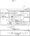
- FIG. 11 is a detailed configuration diagram of the entire system of the control system 2 including the light distribution control system and the database device according to the second embodiment.
- the light distribution control system 40 of the control system 2 is a portion corresponding to the outside world sensor 11 and the recognition processing device 100 of FIG. 2 (that is, a sensing system that recognizes the outside world of a vehicle). ) Is not provided.
- the light distribution processing device 200 of the light distribution control system 40 shown in FIG. 11 repeatedly executes the flowchart shown in FIG. 4 at a predetermined control cycle.
- step S201 the illuminance acquisition unit 203 acquires the illuminance information from the illuminance sensor 12.
- step S202 when the illuminance acquired in step S201 is less than the threshold value, the processes after step S203 are performed.
- step S203 the position information acquisition unit 204 acquires position information from the position information sensor 13.
- step S204 the location information acquired in step S203 is transmitted from the communication unit 206 to the database device 30 via the network 20, and the obstacle stored in the server 32 from the database device 30 based on the location information. Read out the area information where there is a risk of collision.
- Step S205 Area information at risk of collision with an obstacle transmitted from the communication unit 31 via the network 20 is received by the communication unit 206 of the light distribution processing device 200, and is received by the light distribution control unit 205 with the received obstacle. Get information on areas where there is a risk of collision.
- step S205 for example, the travel path information of the own vehicle is acquired by estimating the travel path information of the own vehicle from the position information or acquiring the route information of the own vehicle from the navigation system.
- step S206 it is determined whether or not the area information at risk of collision with the obstacle acquired in step S204 exists on the traveling path of the own vehicle acquired in step S205, and the obstacle is found on the traveling path of the own vehicle.
- the processing after step S207 is performed only when the area information at which there is a risk of collision exists.
- the distance from the vehicle to the obstacle at the time when the obstacle recognition unit 103 first recognizes the obstacle is used. Therefore, it may be determined whether or not to read the light distribution control area information for which the area for which light distribution control is required is determined from the database device 30.
- step S207 when the high beam of the headlight 14 is a scene necessary for danger prevention, the processing after step S208 is performed as the area information in which there is a risk of collision with the obstacle acquired in step S204.
- step S208 when the vehicle is equipped with a light distribution control function such as AHB or ADB, the processes after step S209 are performed.
- step S209 the light distribution control function such as AHB or ADB is enabled.
- step S210 in the case of a scene other than the scene where the high beam of the headlight 14 is necessary for danger prevention in step S207 and the vehicle in which the light distribution control function is not installed in step S208, the notification device 15 informs the driver of the vehicle. Notify the recommendation of high beam switching of the headlight 14.
- the light distribution control area information for determining the area requiring light distribution control corresponding to the position information of the vehicle 1A is read from the database device 32 (server 32), and the vehicle 1A progresses. After determining whether or not it exists on the road, control corresponding to the light distribution control area information that determines the area for which light distribution control is required is performed.
- the light distribution control system 40 of the second embodiment is a light distribution control system that controls the light distribution of the headlights of the vehicle, and is an illuminance acquisition that acquires information on the illuminance around the vehicle.
- the position information acquisition unit 204 for acquiring the position information of the vehicle, and the database device 30 in which the light distribution control area information for determining the area requiring the light distribution control is written.
- the light distribution control of the headlight is performed, or the driver of the vehicle is notified via the notification device.
- a light distribution control unit 205 for notifying the recommendation of switching the high beam of the headlight is provided.
- the information of the area necessary for the high beam to prevent danger is acquired from the server based on the position information, and when the area is on the traveling path, the driver is notified of the recommendation of switching the high beam. Therefore, it is possible to alert the driver even if the vehicle is not equipped with a headlight that can control the light distribution.
- FIG. 12 is a detailed configuration diagram of the entire system of the control system 3 including the sensing system and the database device according to the third embodiment.
- the sensing system 50 of the control system 3 recognizes the outside world of the vehicle in order to control the light distribution of the headlights of the vehicle, and the headlight 14 for controlling the light distribution of the first embodiment and the notification. It does not have the device 15. Further, the information integration processing device 300 is provided in place of the light distribution processing device 200, and the information integration processing unit 301 is provided in place of the light distribution control unit 205. The information integration processing device 300 and the information integration processing unit 301 are the same as the light distribution processing device 200 and the light distribution control unit 205 shown in the first embodiment, except that the light distribution control of the headlight 14 is not performed, respectively.
- the recognition processing device 100 and the information integration processing device 300 of the sensing system 50 shown in FIG. 12 repeatedly execute the flowchart shown in FIG. 3 at a predetermined control cycle.
- step S101 the recognition processing device 100 and the information integrated processing device 300 acquire sensor information from the outside world sensor 11, the illuminance sensor 12, and the position information sensor 13.
- step S102 day / night determination is performed from the sensor information acquired from the sensor (for example, using information such as illuminance and image brightness), and the processing after step S104 is executed only when it is determined to be night in step S103. ..
- step S104 the obstacle recognition unit 103 of the recognition processing device 100 recognizes an obstacle in front of or around the vehicle 1A (specifically, an obstacle on the traveling path of the vehicle 1A), and in step S105, recognition is performed in step S104.
- step S107 The processing after step S107 is executed only when it is determined in step S106 that there is a risk of collision with an obstacle. As a result, it is possible to determine in the subsequent steps whether or not the high beam is necessary for danger prevention only in the area where there is a risk of collision with an obstacle, and upload the information to the server 32 of the database device 30.
- the illuminance acquisition unit 203 of the information integration processing device 300 acquires the illuminance information around the vehicle 1A from the illuminance sensor 12.
- step S107 when the illuminance acquired in step S107 is less than the threshold value in step S108, and the distance to the obstacle identified in step S104 in step S109 (recognition start distance). If the distance from the vehicle to the obstacle at the time when the obstacle recognition unit 103 first recognizes the obstacle) is less than the threshold value, it is determined in step S110 that the scene (area) requires a high beam for danger prevention. ..
- step S111 it is determined that the area has a risk of collision, and it is recommended to travel with a high beam while traveling because the surrounding area is bright or an obstacle can be recognized even in a distant place.
- the database device 30 by transmitting the created area information (experience information) that may collide with the obstacle from the communication unit 206 to the database device 30 via the network 20, the area information that has the risk of colliding with the obstacle (experience information). (Experience information) is stored in the database device 30 and shared with other vehicles.
- the sensing system 50 of the third embodiment is a sensing system that recognizes the outside world of the vehicle in order to control the light distribution of the headlight of the vehicle, and is information on the illuminance around the vehicle.
- the illuminance acquisition unit 203 for acquiring the light intensity acquisition unit 203, the obstacle recognition unit (object recognition unit) 103 for recognizing the distance from the vehicle to the object on the traveling path of the vehicle, and the position information acquisition unit for acquiring the position information of the vehicle.
- a writing device that writes to the database device 30 the light distribution control area information that determines the area that requires light distribution control based on the illuminance and the distance, or the illuminance and the distance, together with the position information of the vehicle and the unit 204. And prepare.
- the high beam is accumulated by determining whether the high beam is an area necessary for danger prevention (an area where there is a risk of collision with an obstacle and light distribution control is necessary). It is possible to store useful information in the server when switching.
- the present invention is not limited to the above-described embodiment, but includes various modifications.
- the above-described embodiment has been described in detail in order to explain the present invention in an easy-to-understand manner, and is not necessarily limited to the one including all the described configurations.
- each of the above configurations, functions, processing units, processing means, etc. may be realized by hardware by designing a part or all of them by, for example, an integrated circuit. Further, each of the above configurations, functions, and the like may be realized by software by the processor interpreting and executing a program that realizes each function. Information such as programs, tables, and files that realize each function can be stored in a memory, a hard disk, a storage device such as an SSD (Solid State Drive), or a recording medium such as an IC card, an SD card, or a DVD.
- SSD Solid State Drive
- control lines and information lines indicate those that are considered necessary for explanation, and do not necessarily indicate all control lines and information lines in the product. In practice, it can be considered that almost all configurations are interconnected.
- Light distribution control system including sensing system and control system of database device 2 Control system of light distribution control system and database device 3 Control system of sensing system and database device 4 Distance from vehicle to obstacle 5 Obstacle (pedestrian, etc.) Objects that can be obstacles, including moving objects) 6 Street light 7 Area where there is a risk of collision with obstacles 8 Path 9 Range to acquire information from the server 10
- Light distribution control system 11 External sensor 12 Illumination sensor 13 Position information sensor 14 Headlight 15 Notification device 20 Network 30 Database device 31 Communication unit 32 Server 40
- Light distribution control system 50 Sensing system 100 Recognition processing device 101 Central processing device 102 Storage device 103 Obstacle recognition unit (object recognition unit) 104 Light spot identification unit 200 Light distribution processing unit 201 Central processing unit 202 Storage device 203 Illuminance acquisition unit 204 Position information acquisition unit 205 Light distribution control unit 206 Communication unit 300 Information integration processing device 301 Information integration processing unit
Landscapes
- Engineering & Computer Science (AREA)
- Mechanical Engineering (AREA)
- Human Computer Interaction (AREA)
- Lighting Device Outwards From Vehicle And Optical Signal (AREA)
- Traffic Control Systems (AREA)
- Navigation (AREA)
Abstract
Description
図1~図10を参照して、本発明の実施例1に係るセンシングシステムを含む配光制御システムを説明する。
図1は、本実施例1に係るセンシングシステムを含む配光制御システム及びデータベース装置で構成される制御システム1のシステム全体の概略構成図である。図2に、本実施例1に係る制御システム1のシステム全体の詳細な構成図を示す。
次に、配光制御システム10の各構成要素について説明する。
外界センサ11は、車両1Aの前方などに設置され、車両1Aの前方または周囲の情報(センサ情報)を取得するセンサである。外界センサ11は、車両1Aの前方や周囲の画像を撮像することのできるステレオカメラ、単眼カメラ、物体の距離や角度を取得することのできるミリ波レーダーや物体の3次元情報を取得することのできるLiDAR(Light Detection And Ranging)などを利用することができる。
照度センサ12は、車両1Aのダッシュボード上やフロントウィンドウなどに取り付けられた車両1Aの周囲の照度情報を取得することのできるセンサである。
位置情報センサ13は、車両1Aや、車両1Aに設置されたナビゲーションシステムに設置されているGPS(全地球測位システム)衛星より位置情報を受信するGPS受信機や、ステレオカメラやLiDARなどの外界センサ11で取得できる車両1Aの周囲の3次元情報より、配光処理装置200の記憶装置202に記憶された3次元地図データ上での位置を推定するアルゴリズムを実行することで位置情報を取得する方法を利用するものでもよい。
ヘッドライト14は、車両1Aの前方に設置され、配光処理装置200の出力結果に基づいて、ハイビームとロービームを切り替えることのできるヘッドライトや、複数のヘッドライトの光軸を変化させるアクチュエータ(例えば複数のモータ)や、各ヘッドライトの光の一部を遮蔽するためのシェード機構が設けられ、ヘッドライトの照射向きや照射範囲を変更することのできるヘッドライトが利用できる。
通知装置15は、車両1Aに設置され、配光処理装置200の出力結果に基づいて、ドライバーへヘッドライト14のハイビーム切り替えの推奨を通知する。例えば、メーターパネルへハイビーム切り替えの推奨を文字や記号、画像やアニメーションなどで通知したり、音声により通知したりしても良い。
認識処理装置100と配光処理装置200は、それぞれコンピュータであり、図2に示すように、例えば、入力部と、プロセッサである中央処理装置101、201(CPU又はMPU)と、記憶装置102、202であるリードオンリーメモリ(ROM)及びランダムアクセスメモリ(RAM)と、出力部とをそれぞれ有している。このうち入力部は、認識処理装置100及び配光処理装置200に入力される各種情報を、CPUが演算可能なように変換する。ROMは、適宜後述する演算処理を実行する制御プログラムと、当該演算処理の実行に必要な各種情報等が記憶された記録媒体であり、CPUは、ROMに記憶された制御プログラムに従って入力部及びROM、RAMから取り入れた信号に対して所定の演算処理を行う。出力部からは、出力対象を制御するための指令や出力対象が利用する情報等が出力される。なお、記憶装置102、202は上記のROM及びRAMという半導体メモリに限られず、例えばハードディスクドライブ等の磁気記憶装置に代替可能である。
認識処理装置100の中央処理装置101は、演算処理ブロックとして、障害物認識部(対象物認識部)103と光点識別部104を備える。
認識処理装置100の障害物認識部103では、外界センサ11で取得した情報より、車両1Aの前方または周囲の障害物5(図1)を認識する。例えば、ステレオカメラやLiDARなどで取得した3次元情報を利用し、車両1Aの前方または周囲の障害物を立体物として認識する方法を用いる。
認識処理装置100の光点識別部104では、外界センサ11で取得した情報より、車両1Aの前方または周囲の光点を認識する。例えば、ステレオカメラや単眼カメラで撮影した画像より、画像の輝度が一定値以上の画素を検出し、隣接する領域を統合することで、光点領域とする。さらに、光点の輝度情報や車両1Aからの相対距離、車両1Aからの相対位置の情報などを利用して、車両のヘッドライトやテールランプの光点か、それ以外の光点(例えば街灯6(図1))かを識別することで、光点の種類を識別する。または、ステレオカメラやLiDARなどで取得した3次元情報、ミリ波レーダーで取得した物体情報と、ステレオカメラや単眼カメラを併用し、立体物情報より車両判定を行うことで、車両のヘッドライトやテールランプの光点か、それ以外の光点かを識別する方法を利用することもできる。
一方、配光処理装置200の中央処理装置201は、演算処理ブロックとして、照度取得部203と位置情報取得部204と配光制御部205を備える。
配光処理装置200の照度取得部203では、車両1Aに搭載された照度センサ12より車両1Aの周辺の照度情報を取得する。取得した照度情報は配光制御部205に送られる。
また、配光処理装置200の位置情報取得部204では、位置情報センサ13より車両1Aの位置情報を取得する。取得した位置情報は配光制御部205に送られる。
配光処理装置200の配光制御部205では、ヘッドライト14の配光制御が危険防止に必要なエリア(障害物と衝突の危険があり、配光制御が必要なエリア7(図1))かどうか、認識処理装置100の障害物認識部103で認識した障害物までの距離の情報と、照度取得部203で取得した車両1Aの周辺の照度情報より、シーン毎に分類する。そして、位置情報取得部204で取得した位置情報と合わせてエリア情報(障害物と衝突の危険があり、配光制御が必要なエリアを判断したエリア情報)として通信部206よりネットワーク20を介してデータベース装置30へデータの送信を行う。すなわち、ここでは、配光処理装置200の配光制御部205及び通信部206は、車両1Aの位置情報とともに(関連付けて)、車両1Aの周辺の照度情報と障害物までの距離の情報に基づいて配光制御が必要なエリアを判断(分類)した配光制御エリア情報を、データベース装置30(のサーバー32)に書き込む(蓄積する)書き込み装置として機能する。ここで、配光制御システム10において、ヘッドライト14の配光制御が危険防止に必要なエリアかどうかを判定するフローチャート(換言すれば、配光制御部205におけるデータ蓄積時のフローチャート)を図3に示した。
配光制御システム10の認識処理装置100及び配光処理装置200は、図3のフローチャートを所定の制御周期で繰り返し実行している。
次に、実際にステップS110とステップS111で判定し、データベース装置30のサーバー32に蓄積した情報を、配光制御システム10でネットワーク20を介してデータベース装置30から取得し、配光制御システム10の配光処理装置200の配光制御部205でヘッドライト14の配光制御に利用するフローを説明する。なお、図示例では、車両1Aに備えられた配光制御システム10でネットワーク20を介してデータベース装置30のサーバー32に蓄積した情報を、車両1Aに備えられた配光制御システム10でネットワーク20を介してデータベース装置30から取得する、すなわちデータベース装置30にデータを蓄積する車両と、データベース装置30からデータを取得する車両とが同じ車両として記載しているが、データベース装置30にデータを蓄積する車両と、データベース装置30からデータを取得する車両とが異なる車両でもよいことは当然である。
以上で説明したように、本実施例1の配光制御システム10は、車両の外界認識を行うセンシングシステムを含み、車両のヘッドライトの配光を制御する配光制御システムであって、前記車両の周囲の照度の情報を取得する照度取得部203と、前記車両から前記車両の進行路上の対象物までの距離を認識する障害物認識部(対象物認識部)103と、前記車両の位置情報を取得する位置情報取得部204と、前記車両の位置情報とともに、前記照度と前記距離、または前記照度と前記距離に基づいて配光制御が必要なエリアを判断した配光制御エリア情報を、データベース装置30に書き込む書き込み装置と、前記データベース装置30から、前記車両の位置情報に対応する前記配光制御エリア情報を読み出す読み出し装置と、前記読み出された前記配光制御エリア情報に基づき、前記ヘッドライトの配光制御を行う、または、通知装置を介して前記車両の運転手に前記ヘッドライトのハイビーム切り替えの推奨を通知する配光制御部205と、を備える。
次に、図11を参照して、本発明の実施例2に係る配光制御システムを説明する。
以上で説明したように、本実施例2の配光制御システム40は、車両のヘッドライトの配光を制御する配光制御システムであって、前記車両の周囲の照度の情報を取得する照度取得部203と、前記車両の位置情報を取得する位置情報取得部204と、配光制御が必要なエリアを判断した配光制御エリア情報が書き込まれたデータベース装置30から、前記車両の位置情報に対応する前記配光制御エリア情報を読み出す読み出し装置と、前記読み出された前記配光制御エリア情報に基づき、前記ヘッドライトの配光制御を行う、または、通知装置を介して前記車両の運転手に前記ヘッドライトのハイビーム切り替えの推奨を通知する配光制御部205と、を備える。
次に、図12を参照して、本発明の実施例3に係る配光制御システムに好適に利用可能なセンシングシステムを説明する。
以上で説明したように、本実施例3のセンシングシステム50は、車両のヘッドライトの配光を制御するために、車両の外界認識を行うセンシングシステムであって、前記車両の周囲の照度の情報を取得する照度取得部203と、前記車両から前記車両の進行路上の対象物までの距離を認識する障害物認識部(対象物認識部)103と、前記車両の位置情報を取得する位置情報取得部204と、前記車両の位置情報とともに、前記照度と前記距離、または前記照度と前記距離に基づいて配光制御が必要なエリアを判断した配光制御エリア情報を、データベース装置30に書き込む書き込み装置と、を備える。
2 配光制御システム及びデータベース装置の制御システム
3 センシングシステム及びデータベース装置の制御システム
4 車両から障害物までの距離
5 障害物(歩行者等の移動体を含む、障害となり得る対象物)
6 街灯
7 障害物との衝突の危険のあるエリア
8 進行路
9 サーバーから情報を取得する範囲
10 配光制御システム
11 外界センサ
12 照度センサ
13 位置情報センサ
14 ヘッドライト
15 通知装置
20 ネットワーク
30 データベース装置
31 通信部
32 サーバー
40 配光制御システム
50 センシングシステム
100 認識処理装置
101 中央処理装置
102 記憶装置
103 障害物認識部(対象物認識部)
104 光点識別部
200 配光処理装置
201 中央処理装置
202 記憶装置
203 照度取得部
204 位置情報取得部
205 配光制御部
206 通信部
300 情報統合処理装置
301 情報統合処理部
Claims (9)
- 車両の外界認識を行うセンシングシステムを含み、車両のヘッドライトの配光を制御する配光制御システムであって、
前記車両の周囲の照度の情報を取得する照度取得部と、
前記車両から前記車両の進行路上の対象物までの距離を認識する対象物認識部と、
前記車両の位置情報を取得する位置情報取得部と、
前記車両の位置情報とともに、前記照度と前記距離、または前記照度と前記距離に基づいて配光制御が必要なエリアを判断した配光制御エリア情報を、データベース装置に書き込む書き込み装置と、
前記データベース装置から、前記車両の位置情報に対応する前記配光制御エリア情報を読み出す読み出し装置と、
前記読み出された前記配光制御エリア情報に基づき、前記ヘッドライトの配光制御を行う、または、通知装置を介して前記車両の運転手に前記ヘッドライトのハイビーム切り替えの推奨を通知する配光制御部と、を備えることを特徴とする配光制御システム。 - 請求項1に記載の配光制御システムにおいて、
前記車両外に、前記車両の位置情報とともに書き込まれた前記照度と前記距離に基づいて前記配光制御エリア情報を作成する演算装置を有することを特徴とする配光制御システム。 - 請求項1に記載の配光制御システムにおいて、
前記書き込み装置は、前記照度取得部で取得した照度と、前記対象物認識部が前記対象物をはじめて認識した時点における前記車両から前記対象物までの距離とに基づいて、前記配光制御エリア情報を前記データベース装置に書き込むか否かを判断することを特徴とする配光制御システム。 - 請求項1に記載の配光制御システムにおいて、
前記読み出し装置は、前記照度取得部で取得した照度と、前記対象物認識部が前記対象物をはじめて認識した時点における前記車両から前記対象物までの距離とに基づいて、前記データベース装置から前記配光制御エリア情報を読み出すか否かを判断することを特徴とする配光制御システム。 - 請求項1に記載の配光制御システムにおいて、
前記書き込み装置は、前記照度が第1閾値未満、かつ、前記距離が第2閾値未満の場合、前記対象物との衝突の危険防止にハイビームが必要なエリアと判定し、前記照度が第1閾値以上、または、前記距離が第2閾値以上の場合、ハイビームで走行することを推奨する前記対象物との衝突の危険のあるエリアと判定し、前記データベース装置に書き込むことを特徴とする配光制御システム。 - 請求項1に記載の配光制御システムにおいて、
前記読み出し装置は、前記車両の位置情報周辺の一定の閾値の範囲の前記配光制御エリア情報を読み出すことを特徴とする配光制御システム。 - 請求項1に記載の配光制御システムにおいて、
前記配光制御部は、前記読み出された前記配光制御エリア情報が前記車両の進行路上に存在する場合のみ、前記ヘッドライトの配光制御を行う、または、通知装置を介して前記車両の運転手に前記ヘッドライトのハイビーム切り替えの推奨を通知することを特徴とする配光制御システム。 - 車両のヘッドライトの配光を制御する配光制御システムであって、
前記車両の周囲の照度の情報を取得する照度取得部と、
前記車両の位置情報を取得する位置情報取得部と、
配光制御が必要なエリアを判断した配光制御エリア情報が書き込まれたデータベース装置から、前記車両の位置情報に対応する前記配光制御エリア情報を読み出す読み出し装置と、
前記読み出された前記配光制御エリア情報に基づき、前記ヘッドライトの配光制御を行う、または、通知装置を介して前記車両の運転手に前記ヘッドライトのハイビーム切り替えの推奨を通知する配光制御部と、を備えることを特徴とする配光制御システム。 - 車両のヘッドライトの配光を制御するために、車両の外界認識を行うセンシングシステムであって、
前記車両の周囲の照度の情報を取得する照度取得部と、
前記車両から前記車両の進行路上の対象物までの距離を認識する対象物認識部と、
前記車両の位置情報を取得する位置情報取得部と、
前記車両の位置情報とともに、前記照度と前記距離、または前記照度と前記距離に基づいて配光制御が必要なエリアを判断した配光制御エリア情報を、データベース装置に書き込む書き込み装置と、を備えることを特徴とするセンシングシステム。
Priority Applications (2)
| Application Number | Priority Date | Filing Date | Title |
|---|---|---|---|
| DE112021005254.3T DE112021005254B4 (de) | 2020-12-15 | 2021-11-15 | Lichtverteilungssteuerungssystem und -erfassungssystem |
| JP2022569787A JP7461512B2 (ja) | 2020-12-15 | 2021-11-15 | 配光制御システム及びセンシングシステム |
Applications Claiming Priority (2)
| Application Number | Priority Date | Filing Date | Title |
|---|---|---|---|
| JP2020-207195 | 2020-12-15 | ||
| JP2020207195 | 2020-12-15 |
Publications (1)
| Publication Number | Publication Date |
|---|---|
| WO2022130866A1 true WO2022130866A1 (ja) | 2022-06-23 |
Family
ID=82059057
Family Applications (1)
| Application Number | Title | Priority Date | Filing Date |
|---|---|---|---|
| PCT/JP2021/041841 Ceased WO2022130866A1 (ja) | 2020-12-15 | 2021-11-15 | 配光制御システム及びセンシングシステム |
Country Status (3)
| Country | Link |
|---|---|
| JP (1) | JP7461512B2 (ja) |
| DE (1) | DE112021005254B4 (ja) |
| WO (1) | WO2022130866A1 (ja) |
Cited By (1)
| Publication number | Priority date | Publication date | Assignee | Title |
|---|---|---|---|---|
| JP2025127074A (ja) * | 2024-02-20 | 2025-09-01 | トヨタ自動車株式会社 | 車両用配光制御装置 |
Families Citing this family (1)
| Publication number | Priority date | Publication date | Assignee | Title |
|---|---|---|---|---|
| DE102024003413B3 (de) | 2024-10-17 | 2026-02-12 | Mercedes-Benz Group AG | Lichtverteileinrichtung, Fahrzeug mit Lichtverteileinrichtung und Verfahren zum Betrieb einer Lichtverteileinrichtung |
Citations (3)
| Publication number | Priority date | Publication date | Assignee | Title |
|---|---|---|---|---|
| JP2019104351A (ja) * | 2017-12-12 | 2019-06-27 | トヨタ自動車株式会社 | 車両システム、車両、及び情報処理装置 |
| JP2019520262A (ja) * | 2016-06-24 | 2019-07-18 | ジェンテックス コーポレイション | 適応ハイビーム制御を用いた撮像システム |
| WO2019244340A1 (ja) * | 2018-06-22 | 2019-12-26 | 三菱電機株式会社 | ヘッドライト制御装置及びヘッドライト制御方法 |
Family Cites Families (3)
| Publication number | Priority date | Publication date | Assignee | Title |
|---|---|---|---|---|
| JP4526700B2 (ja) * | 2000-12-27 | 2010-08-18 | 株式会社エクォス・リサーチ | 配光制御装置 |
| JP6485435B2 (ja) * | 2016-12-07 | 2019-03-20 | トヨタ自動車株式会社 | 制御用データ生成装置および車両用制御装置 |
| WO2020045318A1 (ja) * | 2018-08-31 | 2020-03-05 | 株式会社デンソー | 車両側装置、サーバ、方法および記憶媒体 |
-
2021
- 2021-11-15 WO PCT/JP2021/041841 patent/WO2022130866A1/ja not_active Ceased
- 2021-11-15 JP JP2022569787A patent/JP7461512B2/ja active Active
- 2021-11-15 DE DE112021005254.3T patent/DE112021005254B4/de active Active
Patent Citations (3)
| Publication number | Priority date | Publication date | Assignee | Title |
|---|---|---|---|---|
| JP2019520262A (ja) * | 2016-06-24 | 2019-07-18 | ジェンテックス コーポレイション | 適応ハイビーム制御を用いた撮像システム |
| JP2019104351A (ja) * | 2017-12-12 | 2019-06-27 | トヨタ自動車株式会社 | 車両システム、車両、及び情報処理装置 |
| WO2019244340A1 (ja) * | 2018-06-22 | 2019-12-26 | 三菱電機株式会社 | ヘッドライト制御装置及びヘッドライト制御方法 |
Cited By (1)
| Publication number | Priority date | Publication date | Assignee | Title |
|---|---|---|---|---|
| JP2025127074A (ja) * | 2024-02-20 | 2025-09-01 | トヨタ自動車株式会社 | 車両用配光制御装置 |
Also Published As
| Publication number | Publication date |
|---|---|
| JPWO2022130866A1 (ja) | 2022-06-23 |
| DE112021005254T5 (de) | 2023-09-07 |
| DE112021005254B4 (de) | 2026-01-29 |
| JP7461512B2 (ja) | 2024-04-03 |
Similar Documents
| Publication | Publication Date | Title |
|---|---|---|
| JP5409929B2 (ja) | 車両用ヘッドライト装置の制御方法およびヘッドライト装置 | |
| JP4253271B2 (ja) | 画像処理システム及び車両制御システム | |
| US9481292B2 (en) | Method and control unit for influencing a lighting scene ahead of a vehicle | |
| JP5207146B2 (ja) | 遠距離灯の自動制御方法 | |
| JP4253275B2 (ja) | 車両制御システム | |
| CN104185588B (zh) | 用于确定道路宽度的车载成像系统及方法 | |
| CN103097196B (zh) | 用于在不清晰的弯道中调整车辆的照明的装置和方法 | |
| US9527429B2 (en) | Method and device for controlling a light emission of at least one headlight of a vehicle | |
| JP5980899B2 (ja) | 車両用の照明システムのヘッドライトレンジを距離に応じて調整するための方法、制御装置、およびコンピュータ読み取り可能な記録媒体 | |
| EP3475121B1 (en) | Imaging system with adaptive high beam control | |
| JP5313638B2 (ja) | 車両用前照灯装置 | |
| JP2014515893A (ja) | 車両のカメラによって撮影した画像を評価するための方法および画像評価装置 | |
| US9616805B2 (en) | Method and device for controlling a headlamp of a vehicle | |
| JP7081444B2 (ja) | 車両制御システム | |
| JP5361901B2 (ja) | 前照灯制御装置 | |
| JP7461512B2 (ja) | 配光制御システム及びセンシングシステム | |
| US20240190331A1 (en) | Methods and apparatuses for adaptive high beam control for a vehicle | |
| Sevekar et al. | Nighttime vehicle detection for intelligent headlight control: A review | |
| CN115402189A (zh) | 车辆控制方法、装置及车辆 | |
| WO2025022743A1 (ja) | 配光制御装置及び配光制御方法 | |
| JP7378673B2 (ja) | 前照灯制御装置、前照灯制御システム、及び前照灯制御方法 | |
| JP5643877B2 (ja) | 車両用前照灯装置 | |
| CN111241972A (zh) | 一种车辆控制方法、装置、车辆及计算机可读存储介质 | |
| JP7599624B1 (ja) | 配光制御装置及び配光制御方法 | |
| EP4738291A1 (en) | Methods and systems for object detection |
Legal Events
| Date | Code | Title | Description |
|---|---|---|---|
| 121 | Ep: the epo has been informed by wipo that ep was designated in this application |
Ref document number: 21906230 Country of ref document: EP Kind code of ref document: A1 |
|
| ENP | Entry into the national phase |
Ref document number: 2022569787 Country of ref document: JP Kind code of ref document: A |
|
| WWE | Wipo information: entry into national phase |
Ref document number: 112021005254 Country of ref document: DE |
|
| 122 | Ep: pct application non-entry in european phase |
Ref document number: 21906230 Country of ref document: EP Kind code of ref document: A1 |
|
| WWG | Wipo information: grant in national office |
Ref document number: 112021005254 Country of ref document: DE |