WO2022130824A1 - 電池システム - Google Patents
電池システム Download PDFInfo
- Publication number
- WO2022130824A1 WO2022130824A1 PCT/JP2021/040814 JP2021040814W WO2022130824A1 WO 2022130824 A1 WO2022130824 A1 WO 2022130824A1 JP 2021040814 W JP2021040814 W JP 2021040814W WO 2022130824 A1 WO2022130824 A1 WO 2022130824A1
- Authority
- WO
- WIPO (PCT)
- Prior art keywords
- battery
- storage battery
- discharge
- time
- charging
- Prior art date
- Legal status (The legal status is an assumption and is not a legal conclusion. Google has not performed a legal analysis and makes no representation as to the accuracy of the status listed.)
- Ceased
Links
Images


Classifications
-
- H—ELECTRICITY
- H02—GENERATION; CONVERSION OR DISTRIBUTION OF ELECTRIC POWER
- H02J—ELECTRIC POWER NETWORKS; CIRCUIT ARRANGEMENTS OR SYSTEMS FOR SUPPLYING OR DISTRIBUTING ELECTRIC POWER; SYSTEMS FOR STORING ELECTRIC ENERGY
- H02J7/00—Circuit arrangements for charging or discharging batteries or for supplying loads from batteries
- H02J7/875—Charging or discharging for charge maintenance, battery initiation or rejuvenation
-
- H—ELECTRICITY
- H01—ELECTRIC ELEMENTS
- H01M—PROCESSES OR MEANS, e.g. BATTERIES, FOR THE DIRECT CONVERSION OF CHEMICAL ENERGY INTO ELECTRICAL ENERGY
- H01M10/00—Secondary cells; Manufacture thereof
- H01M10/06—Lead-acid accumulators
-
- H—ELECTRICITY
- H01—ELECTRIC ELEMENTS
- H01M—PROCESSES OR MEANS, e.g. BATTERIES, FOR THE DIRECT CONVERSION OF CHEMICAL ENERGY INTO ELECTRICAL ENERGY
- H01M10/00—Secondary cells; Manufacture thereof
- H01M10/42—Methods or arrangements for servicing or maintenance of secondary cells or secondary half-cells
- H01M10/44—Methods for charging or discharging
-
- H—ELECTRICITY
- H01—ELECTRIC ELEMENTS
- H01M—PROCESSES OR MEANS, e.g. BATTERIES, FOR THE DIRECT CONVERSION OF CHEMICAL ENERGY INTO ELECTRICAL ENERGY
- H01M10/00—Secondary cells; Manufacture thereof
- H01M10/42—Methods or arrangements for servicing or maintenance of secondary cells or secondary half-cells
- H01M10/48—Accumulators combined with arrangements for measuring, testing or indicating the condition of cells, e.g. the level or density of the electrolyte
-
- H—ELECTRICITY
- H02—GENERATION; CONVERSION OR DISTRIBUTION OF ELECTRIC POWER
- H02J—ELECTRIC POWER NETWORKS; CIRCUIT ARRANGEMENTS OR SYSTEMS FOR SUPPLYING OR DISTRIBUTING ELECTRIC POWER; SYSTEMS FOR STORING ELECTRIC ENERGY
- H02J7/00—Circuit arrangements for charging or discharging batteries or for supplying loads from batteries
- H02J7/34—Parallel operation in networks using both storage and other DC sources, e.g. providing buffering
- H02J7/342—The other DC source being a battery actively interacting with the first one, i.e. battery to battery charging
-
- H—ELECTRICITY
- H02—GENERATION; CONVERSION OR DISTRIBUTION OF ELECTRIC POWER
- H02J—ELECTRIC POWER NETWORKS; CIRCUIT ARRANGEMENTS OR SYSTEMS FOR SUPPLYING OR DISTRIBUTING ELECTRIC POWER; SYSTEMS FOR STORING ELECTRIC ENERGY
- H02J7/00—Circuit arrangements for charging or discharging batteries or for supplying loads from batteries
- H02J7/90—Regulation of charging or discharging current or voltage
- H02J7/933—Regulation of charging or discharging current or voltage the cycle being controlled or terminated in response to electric parameters
-
- Y—GENERAL TAGGING OF NEW TECHNOLOGICAL DEVELOPMENTS; GENERAL TAGGING OF CROSS-SECTIONAL TECHNOLOGIES SPANNING OVER SEVERAL SECTIONS OF THE IPC; TECHNICAL SUBJECTS COVERED BY FORMER USPC CROSS-REFERENCE ART COLLECTIONS [XRACs] AND DIGESTS
- Y02—TECHNOLOGIES OR APPLICATIONS FOR MITIGATION OR ADAPTATION AGAINST CLIMATE CHANGE
- Y02E—REDUCTION OF GREENHOUSE GAS [GHG] EMISSIONS, RELATED TO ENERGY GENERATION, TRANSMISSION OR DISTRIBUTION
- Y02E60/00—Enabling technologies; Technologies with a potential or indirect contribution to GHG emissions mitigation
- Y02E60/10—Energy storage using batteries
Definitions
- This invention relates to a battery system.
- the present invention relates to a battery system that controls charging / discharging of a secondary battery such as a lead storage battery.
- the storage battery used in the cycle-use power storage system is generally used by continuously discharging for a long time when the load is operating and charging when the load is not used such as at night. Since the electric power discharged from the storage battery largely depends on the load and it is difficult to control the discharge, much research has not been done so far, and research on the charging method has been continuously proposed.
- the battery system further includes an auxiliary battery
- the controller is characterized in that the auxiliary battery is used as a power source to control the charging operation of the storage battery.
- a pause period is provided after the charging, and the discharge operation for supplying power to the load is controlled again.
- the charging current value in the short charging operation period of the storage battery is characterized in that it is at least twice the discharge current value for supplying electric power to the load.
- the storage battery is characterized by being a lead storage battery.
- controller is characterized in that the frequency of performing the short-time charging operation is adjusted based on the integrated discharge current value of the storage battery.
- the battery system according to the present invention prevents deterioration of the electrode material by periodically performing a short-time charging operation during the discharging operation of the storage battery, that is, focusing on the power supply period to the load. It is a thing.
- the overall configuration of the battery system according to the present invention is shown.
- the timing chart of charge / discharge of the battery system which concerns on this invention is shown.
- the mechanism of the battery system according to the present invention is shown.
- An explanatory diagram of the operation of the battery system according to the present invention is shown.
- Other embodiments of the battery system according to the present invention are shown.
- Other embodiments of the battery system according to the present invention are shown.
- the timing chart of charge / discharge of the battery system which concerns on this invention is shown.
- the experimental result of the battery system which concerns on this invention is shown.
- the image diagram which shows the operation of the controller of the battery system which concerns on this invention is shown.
- FIG. 1 shows the overall configuration of the battery system according to the present invention.
- the main battery device 10 includes a storage battery 11 that serves as a main power source, and a storage battery adjusting circuit 12 that adjusts the charge and discharge of the storage battery 11.
- the auxiliary battery device 20 includes an auxiliary battery 21 and an auxiliary battery adjusting circuit 22 for adjusting the discharge of the auxiliary battery 21.
- the charging / discharging timing of the storage battery adjusting circuit 12 and the auxiliary battery adjusting circuit 22 is controlled by the controller 30.
- the electric power supplied from the main battery device 10 and the auxiliary battery device 20 is adjusted so that it can be used in household electric devices or the like by converting direct current into alternating current by a power conditioner (commonly known as PCS) 40.
- the output of the PCS is connected to a load 50 of a household electric appliance or the like.
- PCS power conditioner
- FIG. 2 shows a time chart of charging / discharging of the storage battery 11.
- the horizontal axis represents time and the vertical axis represents the current value. Below the zero line on the vertical axis, the discharge current value I1 is represented, and above the zero line, the charging current value I2 is represented.
- the storage battery 11 discharges, that is, supplies electric power to the load.
- the storage battery 11 elapses a constant reference time t1 set in the controller 30, not a time determined by the load, the storage battery 11 is forcibly stopped discharging according to a signal from the controller 30. For example, in the case of lighting, even at the timing when lighting is required, the discharge from the storage battery is forcibly stopped and the charging operation is switched to.
- the conventional storage battery continues to discharge to the load and turns off the load (lighting) at the timing when lighting is required, unless there is a reason such as exhaustion of the stored amount. It is different from the fact that the secondary battery was charged at the timing.
- t1 is 38 minutes
- t2 is 2 minutes
- t3 is 10 minutes.
- the storage battery 11 is charged from the auxiliary battery 21 built in the auxiliary battery device 20 by the discharge power. Further, the auxiliary battery device 20 is appropriately supplied so that the power supply to the load 50 is not stopped. That is, the auxiliary battery 21 is not only a power supply source for the main storage battery 11 but also a power supply source for the load 50.
- the auxiliary battery 21 may be a storage battery, but it does not necessarily have to be a storage battery and may be a primary battery.
- the storage battery adjustment circuit 12 and the auxiliary battery adjustment circuit 22 include a semiconductor relay element, and charging / discharging is controlled by turning on / off by a signal from the controller 30.
- the battery system according to the present invention achieves a long life of the storage battery by providing a short forced charging time at a fixed cycle during the discharge period of the storage battery.
- FIG. 3 shows the electrode existing in the electrolyte and the state of lead sulfate deposited on the electrode.
- lead sulfate is deposited on the electrodes, but the state is not always uniform and unevenness (positional non-uniformity) occurs.
- uneven precipitation of lead sulfate can be eliminated by temporarily and forcibly stopping the discharge operation as in the present invention and performing charging for a short time (for example, 2 minutes). ..
- the normal charging here is preferably so-called multi-stage charging in which the amount of charge is changed stepwise.
- the charge time t2 of the storage battery 11 is 10% or less of the discharge time t1. This is because, as described above, the purpose of charging here is not to replenish the amount of stored electricity. Further, it is desirable that the current value I2 during the charging period is at least twice the current value I1 during the discharging period.
- the rest period t3 is provided in order to prevent the diffusion of ions in the electrolytic solution of the storage battery 11. This is especially effective when the storage battery is new.
- the rest period t3 is not indispensable, and may be provided not every cycle but every specific cycle.
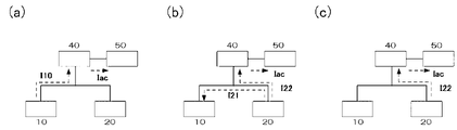
- FIG. 4 more specifically describes the charging / discharging operation of the battery system shown in FIG. (A) represents an operating state at time t1, (b) represents an operating state at time t2, and (c) represents an operating state at time t3.
- (A) corresponds to the time t1 in FIG. 2 and shows the discharge state of the main battery device 10.
- the discharge current I10 from the main battery device 10 flows through the power conditioner 40, and the alternating current Iac from the power conditioner 40 flows through the load 50.
- (B) corresponds to the time t2 in FIG. 2 and shows the charge state of the main battery device 10.
- the discharge current I21 from the auxiliary battery device 20 flows to the main battery device 10
- the discharge current I22 from the auxiliary battery device 20 flows to the power conditioner 40
- the alternating current Iac from the power conditioner 40 flows to the load 50.
- (C) shows the hibernation state of the main battery device 10 in the time corresponding to the time t3 in FIG. Although the discharge from the main battery device 10 is stopped, the power supply to the load 50 is continued by the continuous discharge current I22 from the auxiliary battery device 20.
- the charging period t2 and the rest period t3 it may not be necessary to supply power to the load.
- a large number of battery systems shown in FIG. 1 are used side by side, there is no problem in use by setting the timings of the charging period t2 and the rest period t3 at different times.
- the remaining 99 lights are used. This is because the lighting function in the environment can be maintained by turning on the lighting.
- FIG. 5 shows another embodiment of the battery system of the present invention.
- the auxiliary battery in FIG. 1 is a storage battery, and the storage batteries are forcibly charged with each other.
- the battery system as a whole is composed of the first battery device 10A and the second battery device 10B, and the first battery device 10A is composed of the first storage battery 11A and the adjustment circuit 12A for the first storage battery, and the second battery device. 10B is composed of a second storage battery 11B and an adjustment circuit 12B for the second storage battery.
- the first battery device 10A and the second battery device 10B basically alternate the functions of the main storage battery and the auxiliary battery, and the first battery device 10A becomes the main storage battery.
- the second battery device 10B functions as an auxiliary battery, and when the second battery device 10B serves as the main storage battery, the first battery device 10A functions as an auxiliary battery.
- the first battery device 10A is the main
- the second storage battery 11B becomes the power supply source during the forced short charging period (t2 shown in FIG. 2) of the first storage battery 11A. Is repeated for a certain number of cycles (for example, 100 times).
- the second storage battery 11B becomes the main and the first storage battery 11A assists and takes turns. In this way, both storage batteries repeat the main and auxiliary functions in a fixed cycle, enabling stable use for a longer period of time.
- FIG. 6 shows another embodiment of the battery system according to the present invention.
- four battery devices 10 (10A, 10B, 10C, 10D) are arranged in parallel for one load.
- Each battery device 10 has a built-in storage battery and an adjustment circuit for the storage battery.
- another battery device for example, the second battery device 10B becomes a power supply source for the first battery device 10A.
- the other battery devices 10C and 10D are supplied with power for the load.
- the second battery device 10B comes to perform a forced short charging period, and another battery device, for example, the third battery device 10C becomes a power supply source for the second battery device 10B, and other than that.
- the battery devices 10A and 10D serve as power supply for the load. In this way, by setting the plurality of battery devices so that the forced short charging periods do not overlap each other, all the battery devices can be operated efficiently. Such embodiments are useful in applications that require a large number of storage batteries, such as electric vehicles.
- FIG. 7 shows a mode in which the charge / discharge relationship is further different in the battery system of the embodiment shown in FIG.
- the horizontal axis represents time, and the vertical axis represents the amount of current in each battery system.
- Time T0 is the initial state, and each battery device is neither charging nor discharging.
- each battery device starts discharging all at once.
- the current level (vertical axis) 0 of each battery device is the zero level
- the lower part represents the discharged state
- the upper part represents the charged state.
- the first battery device is in a short-term charging operation state, and the discharge currents of the other battery devices, that is, the second battery device, the third battery device, and the fourth battery device are increased.
- the first battery device has stopped discharging, and other battery devices make up for it.
- the discharge level of the other battery device also returns from the time T1 to the level of the time T2.
- the same operation is repeated while changing the short-term charging operation in the order of the second battery device ⁇ the third battery device ⁇ the fourth battery device.
- This embodiment is different from that shown in FIG. 6 in that when one battery device is in the state of charge, all other battery systems increase the discharge.
- FIG. 8 is an explanatory diagram of an experiment for showing the effect of the present invention
- FIG. 8A shows an example in which the charging / discharging method of the present invention and the conventional charging / discharging method are simultaneously performed using two battery systems.
- (B) show an example in which the charging / discharging method of the present invention was performed using one battery system, a conventional charging / discharging method up to the middle, and then using the same storage battery.
- the vertical axis represents the capacity (%) at full charge of the battery
- the horizontal axis represents the number of experimental cycles
- the black circles represent the method of the present invention
- the black squares represent the conventional method.
- the capacity of the battery is 100% in both the method of the present invention and the conventional method (black circles are difficult to grasp because they overlap in the figure). Can be said to be a new storage battery.
- a discharge of 24 amperes and a charge for 4 hours were set as one set over 1.7 hours, and this was repeated 18 times to make one cycle. That is, the remaining battery capacity (full capacity) after the end of one cycle is 93% (plot with the number of cycles 1 in the figure), while the invention method has 38 minutes of discharge and 2 minutes of forced charge as one set. This was repeated 3 times to make one cycle.
- the remaining battery capacity (full capacity) by the method of the present invention after the end of one cycle is 92% (plot with the number of cycles 1 in the figure).
- the conventional method ( ⁇ ) has decreased from the remaining capacity of 91% in 2 cycles ⁇ the remaining capacity of 90% in 3 cycles ⁇ the remaining capacity of 88% in 4 cycles.
- the remaining capacity is 95% in 2 cycles ⁇ the remaining capacity is 96% in 3 cycles ⁇ the remaining capacity is 96% in 4 cycles ⁇ the remaining capacity is 97% in 5 cycles ⁇ the remaining capacity is 97 in 6 cycles. It can be seen that the remaining capacity increases from 100% in% ⁇ 7 cycles to 101% in 8 cycles. This remaining capacity is the amount of electricity stored when the battery is fully charged, and it is shown that the conventional method has a reduced storage capacity, whereas the invention method has recovered to almost the initial value.
- the battery capacity is 100% in the initial state (number of cycles 0).
- the same conventional method as in (a) above that is, discharging 24 amps over 1.7 hours and charging for 4 hours is set as one set, and this is repeated 18 times to make one cycle, and after 6 cycles.
- the method of the present invention that is, a 38-minute discharge and a 2-minute forced charge were set as one set, and the experiment was repeated three times as one cycle.
- the remaining capacity is 92% in 1 cycle ⁇ the remaining capacity is 90% in 2 cycles ⁇ the remaining capacity is 90% in 3 cycles ⁇ the remaining capacity is 94% in 4 cycles ⁇ the remaining capacity is 5 cycles. It can be seen that the capacity is 91%, which is a decrease from the initial capacity.
- the remaining capacity is 95% in 6 cycles ⁇ the remaining capacity is 96% in 7 cycles ⁇ the remaining capacity is 96% in 8 cycles ⁇ the remaining capacity is 97% in 9 cycles ⁇ the remaining capacity is 10 cycles. It can be seen that the remaining capacity increases from 97% in the capacity ⁇ 100% in the remaining capacity in 11 cycles ⁇ 101% in the number of 12 cycles. As a result, it is shown that by adopting the invention method, the storage capacity lowered by the conventional method is restored to almost the initial value.
- the controller can adjust the current value of the pause period, the short charging operation period, or the charging operation period based on the usage time of the storage battery or the integrated value of the discharge current.
- FIG. 9 is an image diagram for explaining such control.
- the vertical mass is the capacity at full charge and represents the ratio when the initial value is 100%, and the horizontal mass represents the integrated value of the discharge current.
- numerical values are stored in each cell in the form of (a, b, c), where a is the short-time charging time t2 (see FIG. 2 and the same applies hereinafter), and b is the time of the rest period following the short-time charging.
- t3 and c represent the current value I2 for short-time charging, respectively, and the controller stores a table in which such numerical values are set in advance.
- the controller changes the short-time charge time t2 to a2 and pauses following the short-time charge.
- the time t3 of the period is b1, and the current value of the short-time charge is c1.
- the controller changes the short-time charge time t2 to a2 and pauses following the short-time charge.
- the time t3 of the period and the current value of the short-time charge are also changed to b2 and c2, respectively.
- the controller measures the fully charged capacity of the storage battery when the integrated value of the discharge current reaches a predetermined value, and accordingly, the short-time charge time and the short-time charge-following pause period.
- the current value of time and short-time charge is corrected.
- the full charge of the storage battery reaches a predetermined value, for example, 60%, the storage battery can be displayed as a warning as its life.
- the controller can also adjust the frequency of short-time charging operation based on the integrated value of the discharge current of the storage battery.
- the controller stores a table corresponding to the integrated value of the discharge current value. In other words, this is the time of t1 shown in FIG. 2. For example, when the integrated value of the discharge current is 0 Ah, it is 120 minutes, when it is 2500 Ah, it is 60 minutes, and when it is 5000 Ah, it is 40 minutes. ⁇ It turns out that.
- these parameters can be adjusted irregularly, for example, by performing a deterioration diagnosis of the storage battery once a month or a week.
- the discharge is forcibly stopped, the charging operation is performed for a short time, and the charging operation is repeated periodically. It is possible to extend the life of the storage battery.
Landscapes
- Engineering & Computer Science (AREA)
- Manufacturing & Machinery (AREA)
- Chemical & Material Sciences (AREA)
- Chemical Kinetics & Catalysis (AREA)
- Electrochemistry (AREA)
- General Chemical & Material Sciences (AREA)
- Power Engineering (AREA)
- Charge And Discharge Circuits For Batteries Or The Like (AREA)
- Secondary Cells (AREA)
Priority Applications (2)
| Application Number | Priority Date | Filing Date | Title |
|---|---|---|---|
| CN202180084252.5A CN116583982A (zh) | 2020-12-18 | 2021-11-05 | 电池系统 |
| KR1020237020166A KR20230107852A (ko) | 2020-12-18 | 2021-11-05 | 전지 시스템 |
Applications Claiming Priority (2)
| Application Number | Priority Date | Filing Date | Title |
|---|---|---|---|
| JP2020209900A JP2022096755A (ja) | 2020-12-18 | 2020-12-18 | 電池システム |
| JP2020-209900 | 2020-12-18 |
Publications (1)
| Publication Number | Publication Date |
|---|---|
| WO2022130824A1 true WO2022130824A1 (ja) | 2022-06-23 |
Family
ID=82059692
Family Applications (1)
| Application Number | Title | Priority Date | Filing Date |
|---|---|---|---|
| PCT/JP2021/040814 Ceased WO2022130824A1 (ja) | 2020-12-18 | 2021-11-05 | 電池システム |
Country Status (4)
| Country | Link |
|---|---|
| JP (1) | JP2022096755A (https=) |
| KR (1) | KR20230107852A (https=) |
| CN (1) | CN116583982A (https=) |
| WO (1) | WO2022130824A1 (https=) |
Families Citing this family (1)
| Publication number | Priority date | Publication date | Assignee | Title |
|---|---|---|---|---|
| CN119366038A (zh) | 2022-12-28 | 2025-01-24 | 株式会社Lg新能源 | 电池组和包括该电池组的车辆 |
Citations (4)
| Publication number | Priority date | Publication date | Assignee | Title |
|---|---|---|---|---|
| JP2000323188A (ja) * | 1999-05-15 | 2000-11-24 | Jec Service Kk | 鉛電池の活性化法 |
| JP2006352970A (ja) * | 2005-06-14 | 2006-12-28 | Nissan Motor Co Ltd | 電源デバイスの制御装置 |
| JP2014158414A (ja) * | 2013-01-21 | 2014-08-28 | Semiconductor Energy Lab Co Ltd | 蓄電体を有する車両 |
| WO2017094668A1 (ja) * | 2015-12-04 | 2017-06-08 | 株式会社オートネットワーク技術研究所 | 車載用電源装置および車載用電源システム |
Family Cites Families (2)
| Publication number | Priority date | Publication date | Assignee | Title |
|---|---|---|---|---|
| JPS6043734U (ja) | 1983-09-02 | 1985-03-27 | 株式会社 大金製作所 | クラツチデイスク |
| JP3391227B2 (ja) | 1997-09-09 | 2003-03-31 | 松下電器産業株式会社 | 鉛蓄電池の充電方法 |
-
2020
- 2020-12-18 JP JP2020209900A patent/JP2022096755A/ja active Pending
-
2021
- 2021-11-05 CN CN202180084252.5A patent/CN116583982A/zh not_active Withdrawn
- 2021-11-05 KR KR1020237020166A patent/KR20230107852A/ko active Pending
- 2021-11-05 WO PCT/JP2021/040814 patent/WO2022130824A1/ja not_active Ceased
Patent Citations (4)
| Publication number | Priority date | Publication date | Assignee | Title |
|---|---|---|---|---|
| JP2000323188A (ja) * | 1999-05-15 | 2000-11-24 | Jec Service Kk | 鉛電池の活性化法 |
| JP2006352970A (ja) * | 2005-06-14 | 2006-12-28 | Nissan Motor Co Ltd | 電源デバイスの制御装置 |
| JP2014158414A (ja) * | 2013-01-21 | 2014-08-28 | Semiconductor Energy Lab Co Ltd | 蓄電体を有する車両 |
| WO2017094668A1 (ja) * | 2015-12-04 | 2017-06-08 | 株式会社オートネットワーク技術研究所 | 車載用電源装置および車載用電源システム |
Also Published As
| Publication number | Publication date |
|---|---|
| JP2022096755A (ja) | 2022-06-30 |
| KR20230107852A (ko) | 2023-07-18 |
| CN116583982A (zh) | 2023-08-11 |
Similar Documents
| Publication | Publication Date | Title |
|---|---|---|
| JP5322395B2 (ja) | 組電池の充電方法 | |
| US7928698B2 (en) | Battery charging apparatus and method | |
| JP4019734B2 (ja) | 二次電池の運用方法及び二次電池装置 | |
| JP4768088B2 (ja) | 電源システムおよび蓄電池の充電制御方法 | |
| JP5478870B2 (ja) | 蓄電システム及び電力貯蔵システム | |
| EP0348983A2 (en) | Method of charging and discharging battery and power source apparatus adopting the same | |
| EP3566281A1 (en) | System and method for battery pack | |
| US9472976B2 (en) | Storage battery device and charging control method | |
| EA026817B1 (ru) | Генератор биполярных импульсов перенапряжения для аккумулятора и соответствующий способ | |
| US9413037B2 (en) | Cell capacity adjusting device | |
| US11710978B2 (en) | Battery charger and method for charging a battery | |
| US12614915B2 (en) | Energy storage apparatus and charge/discharge control method | |
| WO2021241136A1 (ja) | バックアップ電源装置 | |
| WO2022130824A1 (ja) | 電池システム | |
| JP2010160955A (ja) | 組電池の充電方法 | |
| KR102595567B1 (ko) | 배터리 관리 장치 및 방법 | |
| KR102270913B1 (ko) | 전력저장시스템의 제어 장치와 방법 | |
| JP4933465B2 (ja) | 直流電源システムおよびその充電制御方法 | |
| JP2006325331A (ja) | 二次電池用放電回路並びにそれを具備した二次電池パック及び電子機器 | |
| JP2004304931A (ja) | 蓄電装置の充電方法および充電装置 | |
| JP2009232669A (ja) | バッテリバックアップ装置 | |
| JPH10304590A (ja) | 密閉形鉛蓄電池の充電方法 | |
| JP4758788B2 (ja) | 電源装置 | |
| US5731684A (en) | Method and apparatus for regenerating primary cells | |
| JP2022018347A (ja) | Led照明装置及びその制御方法、並びに植物工場 |
Legal Events
| Date | Code | Title | Description |
|---|---|---|---|
| 121 | Ep: the epo has been informed by wipo that ep was designated in this application |
Ref document number: 21906188 Country of ref document: EP Kind code of ref document: A1 |
|
| WWE | Wipo information: entry into national phase |
Ref document number: 202180084252.5 Country of ref document: CN |
|
| ENP | Entry into the national phase |
Ref document number: 20237020166 Country of ref document: KR Kind code of ref document: A |
|
| NENP | Non-entry into the national phase |
Ref country code: DE |
|
| 122 | Ep: pct application non-entry in european phase |
Ref document number: 21906188 Country of ref document: EP Kind code of ref document: A1 |