WO2022130470A1 - Total heat exchange element and total heat exchange ventilation device - Google Patents
Total heat exchange element and total heat exchange ventilation device Download PDFInfo
- Publication number
- WO2022130470A1 WO2022130470A1 PCT/JP2020/046584 JP2020046584W WO2022130470A1 WO 2022130470 A1 WO2022130470 A1 WO 2022130470A1 JP 2020046584 W JP2020046584 W JP 2020046584W WO 2022130470 A1 WO2022130470 A1 WO 2022130470A1
- Authority
- WO
- WIPO (PCT)
- Prior art keywords
- heat exchange
- total heat
- air
- exchange element
- flow
- Prior art date
Links
- 238000009423 ventilation Methods 0.000 title description 28
- 238000005192 partition Methods 0.000 claims abstract description 90
- 239000000463 material Substances 0.000 claims abstract description 60
- 239000004745 nonwoven fabric Substances 0.000 claims description 54
- 230000035699 permeability Effects 0.000 claims description 31
- XLYOFNOQVPJJNP-UHFFFAOYSA-N water Chemical compound O XLYOFNOQVPJJNP-UHFFFAOYSA-N 0.000 claims description 9
- 230000004888 barrier function Effects 0.000 claims description 5
- 239000000835 fiber Substances 0.000 claims description 5
- 239000012528 membrane Substances 0.000 claims description 4
- 239000004696 Poly ether ether ketone Substances 0.000 claims description 3
- 229920002530 polyetherether ketone Polymers 0.000 claims description 3
- AGBXYHCHUYARJY-UHFFFAOYSA-N 2-phenylethenesulfonic acid Chemical compound OS(=O)(=O)C=CC1=CC=CC=C1 AGBXYHCHUYARJY-UHFFFAOYSA-N 0.000 claims description 2
- 239000002202 Polyethylene glycol Substances 0.000 claims description 2
- 229920001223 polyethylene glycol Polymers 0.000 claims description 2
- 229920002635 polyurethane Polymers 0.000 claims description 2
- 239000004814 polyurethane Substances 0.000 claims description 2
- 238000001179 sorption measurement Methods 0.000 claims 2
- 239000000470 constituent Substances 0.000 claims 1
- 239000011347 resin Substances 0.000 description 48
- 229920005989 resin Polymers 0.000 description 48
- 239000000853 adhesive Substances 0.000 description 21
- 230000001070 adhesive effect Effects 0.000 description 21
- 238000000034 method Methods 0.000 description 13
- 238000004519 manufacturing process Methods 0.000 description 9
- 238000010521 absorption reaction Methods 0.000 description 7
- 238000007791 dehumidification Methods 0.000 description 6
- 238000004378 air conditioning Methods 0.000 description 5
- 238000001816 cooling Methods 0.000 description 5
- 230000000694 effects Effects 0.000 description 5
- 239000007789 gas Substances 0.000 description 5
- 238000010438 heat treatment Methods 0.000 description 5
- 238000012545 processing Methods 0.000 description 5
- 230000036961 partial effect Effects 0.000 description 4
- -1 polypropylene Polymers 0.000 description 4
- 239000004743 Polypropylene Substances 0.000 description 3
- 238000010586 diagram Methods 0.000 description 3
- 229920001155 polypropylene Polymers 0.000 description 3
- IJGRMHOSHXDMSA-UHFFFAOYSA-N Atomic nitrogen Chemical compound N#N IJGRMHOSHXDMSA-UHFFFAOYSA-N 0.000 description 2
- 239000002131 composite material Substances 0.000 description 2
- 230000002209 hydrophobic effect Effects 0.000 description 2
- 238000009434 installation Methods 0.000 description 2
- 238000005304 joining Methods 0.000 description 2
- 239000000123 paper Substances 0.000 description 2
- 239000012466 permeate Substances 0.000 description 2
- 229920000728 polyester Polymers 0.000 description 2
- 230000002829 reductive effect Effects 0.000 description 2
- 239000008400 supply water Substances 0.000 description 2
- 238000012546 transfer Methods 0.000 description 2
- 239000003463 adsorbent Substances 0.000 description 1
- QVGXLLKOCUKJST-UHFFFAOYSA-N atomic oxygen Chemical compound [O] QVGXLLKOCUKJST-UHFFFAOYSA-N 0.000 description 1
- 239000000805 composite resin Substances 0.000 description 1
- 230000008094 contradictory effect Effects 0.000 description 1
- 238000005520 cutting process Methods 0.000 description 1
- 230000007547 defect Effects 0.000 description 1
- 238000009792 diffusion process Methods 0.000 description 1
- 238000007429 general method Methods 0.000 description 1
- 239000003230 hygroscopic agent Substances 0.000 description 1
- 230000001771 impaired effect Effects 0.000 description 1
- 230000002401 inhibitory effect Effects 0.000 description 1
- 230000005764 inhibitory process Effects 0.000 description 1
- 238000005259 measurement Methods 0.000 description 1
- 229910052757 nitrogen Inorganic materials 0.000 description 1
- 239000001301 oxygen Substances 0.000 description 1
- 229910052760 oxygen Inorganic materials 0.000 description 1
- 238000011084 recovery Methods 0.000 description 1
- 239000003507 refrigerant Substances 0.000 description 1
- 230000003068 static effect Effects 0.000 description 1
- 238000003466 welding Methods 0.000 description 1
Images


Classifications
-
- F—MECHANICAL ENGINEERING; LIGHTING; HEATING; WEAPONS; BLASTING
- F24—HEATING; RANGES; VENTILATING
- F24F—AIR-CONDITIONING; AIR-HUMIDIFICATION; VENTILATION; USE OF AIR CURRENTS FOR SCREENING
- F24F7/00—Ventilation
- F24F7/04—Ventilation with ducting systems, e.g. by double walls; with natural circulation
- F24F7/06—Ventilation with ducting systems, e.g. by double walls; with natural circulation with forced air circulation, e.g. by fan positioning of a ventilator in or against a conduit
- F24F7/08—Ventilation with ducting systems, e.g. by double walls; with natural circulation with forced air circulation, e.g. by fan positioning of a ventilator in or against a conduit with separate ducts for supplied and exhausted air with provisions for reversal of the input and output systems
-
- F—MECHANICAL ENGINEERING; LIGHTING; HEATING; WEAPONS; BLASTING
- F28—HEAT EXCHANGE IN GENERAL
- F28F—DETAILS OF HEAT-EXCHANGE AND HEAT-TRANSFER APPARATUS, OF GENERAL APPLICATION
- F28F3/00—Plate-like or laminated elements; Assemblies of plate-like or laminated elements
- F28F3/08—Elements constructed for building-up into stacks, e.g. capable of being taken apart for cleaning
Definitions
- the present disclosure relates to a total heat exchange element and a total heat exchange ventilator capable of exchanging temperature and humidity, that is, total heat between the supply air flow and the exhaust flow.
- the indoor air quality can be systematically secured by ventilation, but considering the cooling and heating efficiency of the air conditioning in the room, the ventilation load, which is the air conditioning load by ventilation, can be suppressed. Ensuring indoor air quality is a contradictory issue.
- a ventilation method that achieves both of these, there is a method of exchanging heat between the supply air flow and the exhaust flow, but in order to further reduce the ventilation load, the temperature, that is, sensible heat, is used between the supply air flow and the exhaust flow.
- total heat exchange which also exchanges humidity, that is, sensible heat, is effective.
- One of the total heat exchange elements which is an element for performing total heat exchange, is a static total heat exchange element in which the supply air passage and the exhaust air passage are formed as independent air passages with a partition plate in between. be.
- the air supply air passage and the exhaust air passage are each composed of a substantially corrugated spacing plate formed by corrugated processing, and the air supply airflow flowing through the air supply air passage and the exhaust flow flowing through the exhaust air passage are described. Total heat exchange takes place between them. Therefore, it is known that the ventilation load can be suppressed and the cooling and heating energy of the indoor air conditioner can be saved by ventilating the indoor air with the total heat exchange ventilation device equipped with the total heat exchange element. There is.
- the humidity recovery direction has been determined by the air conditions including the indoor and outdoor temperatures and humidity. That is, it was not possible to intentionally select the direction of collecting humidity from indoors to outdoors or from outdoors to indoors.
- Patent Document 1 an indoor heat exchanger for air conditioning and a humidifying element are arranged in front of the air supply port of the total heat exchange ventilation device, and in winter, heating with a refrigerant and humidification operation are performed by a humidifying element, and in summer.
- the present disclosure is made in view of the above and is a total heat exchange capable of humidifying or dehumidifying a room depending on the indoor and outdoor air environment without using electric power for humidification and dehumidification.
- the purpose is to obtain an element.
- the total heat exchange element of the present disclosure includes a partition member and a space-holding member for holding a space between the partition members, and the partition member and the space-holding member.
- the partition member is a first surface material which is a material of the surface exposed to the first flow path and a second surface which is a material of the surface exposed to the second flow path and is composed of a material different from the first surface material. With the material.
- the total heat exchange element according to the present disclosure has an effect that the room can be humidified or dehumidified according to the indoor and outdoor air environment without using electric power for humidification and dehumidification.
- Partial vertical cross-sectional view schematically showing an example of the flow path cross section of the exhaust air passage of the total heat exchange element according to the first embodiment.
- Sectional drawing which shows typically an example of the partition member which concerns on Embodiment 1.
- the figure which shows typically the moisture permeability performance of the partition member which concerns on Embodiment 1.
- Top view schematically showing an example of the configuration of the partition member according to the first embodiment on the non-woven fabric layer side.
- Sectional drawing which schematically shows an example of the procedure of the manufacturing method of the total heat exchange element which concerns on Embodiment 1.
- Sectional drawing which shows typically an example of the procedure of the manufacturing method of the total heat exchange element which concerns on Embodiment 1.
- Sectional drawing which schematically shows an example of the procedure of the manufacturing method of the total heat exchange element which concerns on Embodiment 1.
- the figure which shows an example of the schematic structure of the total heat exchange ventilation apparatus which concerns on Embodiment 1.
- Partial vertical cross-sectional view schematically showing another example of the flow path cross section of the exhaust air passage of the total heat exchange element according to the first embodiment.
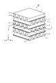
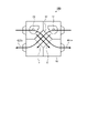
- FIG. 1 is a perspective view schematically showing an example of a schematic configuration of the total heat exchange element according to the first embodiment.
- the extending direction of the first flow path 4 described later is the X direction
- the extending direction of the second flow path 5 orthogonal to the first flow path 4 is the Y direction
- the orthogonal direction is the Z direction.
- the total heat exchange element 10 includes a flat plate-shaped partition member 1, an interval holding member 2, and an adhesive portion 3.
- the partition members 1 are laminated in the Z direction at predetermined intervals.
- the space holding member 2 is a corrugated member that holds the space between the partition members 1 adjacent to each other in the Z direction.
- the corrugated shape refers to a corrugated shape composed of peaks and valleys. In the space holding members 2 adjacent to each other in the Z direction, the extending directions of the peaks and valleys are orthogonal to each other in the plane of the partition member 1, that is, in the XY plane. That is, in the example of FIG.
- the adhesive portion 3 is a portion that joins the mountain portion and the valley portion of the interval holding member 2 and the partition member 1.
- the adhesive portion 3 is a portion where the mountain portion and the valley portion of the interval holding member 2 and the partition member 1 are joined by a joining member such as an adhesive.
- the partition member 1 and the spacing member 2 form a flow path through which air flows in the X and Y directions.
- a first flow path 4 extending in the X direction is formed by the interval holding member 2 in which the extending direction of the mountain portion and the valley portion is the X direction and the partition member 1 joined in the Z direction of the interval holding member 2. Will be done.
- a second flow path 5 extending in the Y direction is formed by the interval holding member 2 in which the extending direction of the mountain portion and the valley portion is the Y direction and the partition member 1 joined in the Z direction of the interval holding member 2. Will be done.
- the first flow path 4 is arranged in layers every other step in the Z direction
- the second flow path 5 is arranged in layers every other step in the Z direction.
- Latent heat and sensible heat are generated between the first air flow 6 which is the flow of air flowing through the first flow path 4 and the second air flow 7 which is the flow of air flowing through the second flow path 5 using the partition member 1 as a medium. Will be exchanged.
- the total heat exchange element 10 has the partition member 1 and the interval holding member 2 for holding the interval between the partition members 1, and the partition member 1 and the interval holding member 2 are alternately laminated and partitioned.
- Temperature and humidity, that is, total heat are transferred between the air flow, which is the flow of air flowing through the first flow path 4 and the second flow path 5, which are composed of the partition member 1 and the spacing member 2 with the member 1 sandwiched between them. It is a device to be replaced.
- the first airflow 6 is a supply airflow that is the flow of air from the outside to the room in the air conditioner including the total heat exchange element 10
- the second airflow 7 is the air flow from the room to the outside in the air conditioner.
- the case of an exhaust flow, which is an air flow, is taken as an example. Further, in this case, the first flow path 4 becomes the supply air passage 4a, and the second flow path 5 becomes the exhaust air passage 5a.
- the space holding member 2 has a corrugated shape, but the space holding member 2 may be any as long as it can hold the space between the partition members 1 at a predetermined space.
- the space holding member 2 may be any as long as it can hold the space between the partition members 1 at a predetermined space.
- a sheet bent into a rectangular wavy shape or a triangular wavy shape, a plurality of plate pieces, or the like may be used.
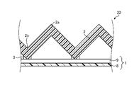
- FIG. 2 is a partial vertical cross-sectional view schematically showing an example of a flow path cross section of an exhaust air passage of the total heat exchange element according to the first embodiment.
- FIG. 2 is a diagram showing the interval holding member 2 and the partition members 1 above and below the interval holding member 2 extracted from the flow path cross section of the exhaust air passage 5a which is the second flow path 5.
- the partition member 1 is a composite membrane including the moisture permeable resin layer 8.
- the moisture permeable resin layer 8 may contain a moisture adsorbent in the air such as a hygroscopic agent.
- the partition member 1 has a moisture-permeable resin layer 8 and a nonwoven fabric layer 9 which is a base material layer.
- the moisture-permeable resin layer 8 and the non-woven fabric layer 9 are in the form of a sheet and are laminated with each other.
- the moisture permeable resin layer 8 is joined to the nonwoven fabric layer 9 with an adhesive or the like.
- the space holding member 2 is a material constituting a normal total heat exchange element such as specially processed paper.
- the total heat exchange element 10 has a form in which the surface of the moisture permeable resin layer 8 of the partition member 1 is exposed to the exhaust air passage 5a, from the exhaust air passage 5a to the supply air passage 4a.
- Moisture permeability that is, humidity exchange can be greatly taken. Further, the humidity exchange from the supply air passage 4a to the exhaust air passage 5a becomes relatively small. As a result, the operation of humidifying from the exhaust air passage 5a to the supply air passage 4a is realized.
- the partition member 1 is exposed to the first surface material which is the material of the surface exposed to the air supply air passage 4a and the exhaust air passage 5a. It can be said that it has a second surface material which is a material of the surface to be exposed and is composed of a material different from the first surface material. At this time, the moisture permeability of the first surface material and the moisture permeability of the second surface material are different from each other.
- the first surface material is a porous membrane material
- the second surface material is a gas barrier membrane having a moisture permeability that allows water vapor to pass through but does not allow oxygen and nitrogen, which are the main components of air, to pass through.
- the first surface material is the non-woven fabric layer 9, and the second surface material is the moisture-permeable resin layer 8.
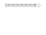
- FIG. 3 is a cross-sectional view schematically showing an example of the partition member according to the first embodiment.
- the partition member 1 is a composite film in which a moisture-permeable resin layer 8 and a non-woven fabric layer 9 which is a base material layer are bonded together.
- the moisture permeable resin layer 8 has a hygroscopic ability to adsorb water vapor in the air, that is, humidity.
- Moisture absorption capacity is defined by the unit area and the amount of moisture absorption per unit time. The amount of moisture absorbed is proportional to the contact area between the moisture permeable resin layer 8 and air.
- the amount of moisture absorbed on the moisture permeable resin layer 8 side of the partition member 1 becomes large.
- the non-woven fabric layer 9 side since the non-woven fabric layer 9 is adhered to the moisture-permeable resin layer 8, the exposed area of the moisture-permeable resin layer 8, that is, the contact area with air is larger than that on the moisture-permeable resin layer 8 side. The amount is reduced, and the moisture absorption area of the nonwoven fabric layer 9 is further hindered by the fixing portion 20 described later. Therefore, the amount of moisture absorbed by the nonwoven fabric layer 9 of the partition member 1 is relatively small.
- the moisture permeability that is, the moisture permeability coefficient P is proportional to the moisture absorption performance S.
- the moisture absorption performance S corresponds to the moisture absorption capacity and is proportional to the contact area between the moisture permeable resin layer 8 and the air, that is, the exposed area of the moisture permeable resin layer 8. That is, the moisture permeability coefficient P is proportional to the exposed area of the moisture permeable resin layer 8.
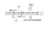
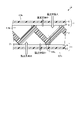
- FIG. 4 is a diagram schematically showing the moisture permeability of the partition member according to the first embodiment. As shown in FIG. 4, the contact area of the moisture permeable resin layer 8 arranged on the exhaust air passage 5a side with air is relative to the contact area of the non-woven fabric layer 9 arranged on the air supply air passage 4a side with air.
- the moisture permeability of the partition member 1 in which the moisture permeable resin layer 8 and the nonwoven fabric layer 9 are joined can greatly increase the moisture permeability from the moisture permeable resin layer 8 side to the nonwoven fabric layer 9 side, and conversely.
- the moisture permeability from the non-woven fabric layer 9 side to the moisture permeable resin layer 8 side can be made relatively small.
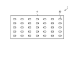
- the non-woven fabric layer 9 has a fixing portion 20 that binds the non-woven fabric fibers to each other by heat welding or an adhesive so as to be united so that the non-woven fabric fibers do not disperse.
- FIG. 5 is a top view schematically showing an example of the configuration of the partition member according to the first embodiment on the non-woven fabric layer side. As shown in FIG. 5, the non-woven fabric layer 9 is provided with a plurality of fixing portions 20.
- the area ratio of the fixing portion 20 to the whole of the non-woven fabric layer 9 contributes to the inhibition of the moisture permeable area.
- the area ratio of the fixing portion 20 to the entire non-woven fabric layer 9 is referred to as the area ratio of the fixing portion 20.
- the difference in moisture permeability between the surface on the moisture permeable resin layer 8 side and the surface on the nonwoven fabric layer 9 side in the partition member 1 It is possible to create. This is because a larger difference in moisture permeability can be created between the surface of the partition member 1 on the moisture permeable resin layer 8 side and the surface on the nonwoven fabric layer 9 side. Further, from the viewpoint of inhibiting the moisture permeation area on the non-woven fabric layer 9 side of the partition member 1, it is desirable that the non-woven fabric material is a hydrophobic resin such as polyester or polypropylene.
- the adhesive area of the nonwoven fabric layer 9 with the moisture permeable resin layer 8 is relatively small. Therefore, the effect of reducing the moisture-permeable area of the moisture-permeable resin layer 8 by the adhesive portion 3 between the nonwoven fabric layer 9 and the moisture-permeable resin layer 8 is smaller than that of the above-mentioned fixing portion 20.
- the adhesive area between the nonwoven fabric layer 9 and the moisture-permeable resin layer 8 it is possible to create a difference in moisture permeability between the surface on the moisture-permeable resin layer 8 side and the surface on the nonwoven fabric layer 9 side. be.
- the moisture-permeable resin layer 8 and the non-woven fabric layer 9 constituting the partition member 1 will be described.
- the moisture permeable resin layer 8 should be made as thin as possible and have as few defects as possible such as pinholes in order to have gas barrier properties. desirable.
- the film thickness of the moisture permeable resin layer 8 is in the range of 5 ⁇ m or more and 30 ⁇ m or less. This is because if the film thickness of the moisture permeable resin layer 8 is less than 5 ⁇ m, the desired gas barrier property may not be obtained, and if the film thickness of the moisture permeable resin layer 8 is thicker than 30 ⁇ m, the desired moisture permeability can be obtained.
- the material of the moisture permeable resin layer 8 is preferably a material that can maintain hydrophilicity, and is any one of hydrophilic polyurethane, polyethylene glycol, styrene sulfonic acid, and sulfonated polyetheretherketone (PEEK). Is desirable.
- the base material layer is a non-woven fabric layer 9 made of a hydrophobic non-woven fabric as described above. If the film thickness of the nonwoven fabric layer 9 is too thin, the mechanical strength at the time of processing cannot be secured, and if it is too thick, the moisture permeability performance of the partition member 1 is impaired. Therefore, the film thickness of the nonwoven fabric layer 9 is in the range of 20 ⁇ m or more and 200 ⁇ m or less. Further, the basis weight of the nonwoven fabric layer 9, that is, the weight of the fiber per unit area [g / m 2 ], has a small difference in in-plane roughness and density from the viewpoint of stability during manufacturing of the partition member 1, that is, the basis weight is as large as possible.
- the basis weight of the non-woven fabric is preferably in the range of 8 g / m 2 or more and 50 g / m 2 or less.
- the gas shielding property of the partition member 1 according to the first embodiment is 5000 seconds / 100 cc or more, preferably 10000 seconds / 100 cc or more in the air permeability resistance measurement by the Gale method or the Oken method as the total heat exchange element 10. be.
- the gas shielding property is in this range, the air is isolated between the air supply air passage 4a and the exhaust air passage 5a, that is, between the air supply and exhaust air, and the ventilation performance can be ensured.
- the heat transfer resistance in the air boundary layer is the main factor in heat exchange between air supply and exhaust, so that the heat transfer property of the material of the partition member 1 is hardly affected.
- the partition member 1 has a two-layer structure of a moisture-permeable resin composite film of the moisture-permeable resin layer 8 and the nonwoven fabric layer 9, but the effect of the first embodiment is exhibited.
- the partition member 1 is not particularly limited to being composed of two resin layers. That is, the partition member 1 may be composed of three or more resin layers.
- the first surface material exposed to the air supply air passage 4a and the second surface member exposed to the exhaust air passage 5a may be made of different materials, more specifically, materials having different moisture permeability.
- FIG. 6 are sectional views schematically showing an example of a procedure of a method for manufacturing a total heat exchange element according to the first embodiment.
- two types of single-sided corrugates are produced. One is, as shown in FIG. 6, a first single surface in which one corrugated spacing member 2 is joined to the moisture permeable resin layer 8 side of one partition member 1 by an adhesive portion 3. Corrugated 21. The other is, as shown in FIG.
- a second single-sided corrugate in which one corrugated spacing member 2 is joined to the non-woven fabric layer 9 side of one partition member 1 by an adhesive portion 3. 22.
- the first single-sided corrugated 21 is a member for forming the exhaust air passage 5a
- the second single-sided corrugated 22 is a member for forming the air supply air passage 4a.
- the method for manufacturing a single-sided corrugated board including the first single-sided corrugated board 21 and the second single-sided corrugated board is a step of making a general corrugated cardboard, and a specially processed paper to be a gap holding member 2 is molded into a corrugated shape and the molded gap holding is performed.
- the member 2 is joined to the partition member 1 by the adhesive portion 3.
- the extending direction of the ridges 2a and the valleys 2b of the spacing member 2 of the first single-sided corrugated 21 and the ridges 2a and the valleys of the spacing member 2 of the second single-sided corrugated 22 is laminated on the first single-sided corrugated plate 21 so as to be orthogonal to the extending direction of the portion 2b, and both are joined by the adhesive portion 3. Then, the first single-sided corrugated 21 and the second single-sided corrugated 22 are similarly laminated so that the first single-sided corrugated 21 and the second single-sided corrugated 22 alternate in the stacking order.
- the extending direction of the mountain portion 2a and the valley portion 2b of the first single-sided corrugated 21 is the X direction
- the extending direction of the mountain portion 2a and the valley portion 2b of the second single-sided corrugated 22 is the Y direction.
- the first single-sided corrugated 21 and the second single-sided corrugated 22 are laminated.
- the partition member 1 is joined to the mountain portion 2a of the uppermost space holding member 2 by the adhesive portion 3.
- the total heat exchange element 10 is obtained by cutting to a predetermined size.
- the total heat exchange element 10 in which the moisture permeable resin layer 8 is arranged on the exhaust air passage 5a side of the partition member 1 and the non-woven fabric layer 9 is arranged on the air supply air passage 4a side is manufactured.
- a method using an adhesive or a thermal bonding method using no adhesive is used for joining by the adhesive portion 3 between the partition member 1 and the space holding member 2.
- the softening temperature is 130 ° C. or higher, for example, when the nonwoven fabric layer 9 is made of a nonwoven fabric mainly made of polyester, it is preferable to use an adhesive from the viewpoint of the mechanical strength of the total heat exchange element 10.
- the non-woven fabric layer 9 is composed of a non-woven fabric mainly composed of a polypropylene component having a softening temperature of less than 130 ° C., for example, a polypropylene component having a low softening temperature, it is better to bond by heat bonding to realize a bonding with excellent water resistance. It is possible.
- the total heat exchange element 10 for dehumidifying the exhaust flow flowing through the exhaust air passage 5a shown in FIGS. 1 and 2 and humidifying the supply airflow flowing through the supply air passage 4a can be obtained.
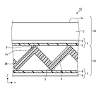
- FIG. 9 is a diagram showing an example of a schematic configuration of the total heat exchange ventilation device according to the first embodiment.
- the total heat exchange ventilation device 100 includes a housing 40, a total heat exchange element 10 according to the first embodiment housed inside the housing 40, a supply air blower 46, and an exhaust blower 47. Inside the housing 40, an air supply flow path 44 for supplying outdoor air to the room and an exhaust flow path 45 for exhausting the indoor air to the outside are provided. At this time, the total heat exchange is such that the supply air passage 4a of the total heat exchange element 10 becomes a part of the supply air flow path 44, and the exhaust air passage 5a becomes a part of the exhaust flow path 45.
- the element 10 is arranged in the housing 40.
- the supply air blower 46 is provided in the supply air flow path 44, and generates an air flow from the outside to the inside of the supply air flow path 44.
- the exhaust blower 47 is provided in the exhaust flow path 45, and generates an air flow from the room to the outside in the exhaust flow path 45.
- the air supply blower 46 and the exhaust blower 47 operate.
- cold and dry outdoor air is passed through the air supply flow path 44 including the air supply air passage 4a as an air supply airflow
- warm and humid indoor air is exhausted as an exhaust flow. It is passed through the exhaust flow path 45 including the air passage 5a.
- the total heat exchange element 10 of the total heat exchange ventilation device 100 two types of airflow, a supply airflow and an exhaust flow, flow across the partition member 1.
- the total heat exchange ventilation device 100 when the total heat exchange ventilation device 100 is operated, the cold and humid outdoor air becomes the air supply air passage 4a.
- the air in the room which is warm and drier than the outdoor air, is passed through the air supply flow path 44 including the exhaust air passage 5a as an exhaust flow.
- the total heat exchange element 10 of the total heat exchange ventilation device 100 two types of airflow, a supply airflow and an exhaust flow, flow across the partition member 1. Heat is transferred between the two types of airflow through the partition member 1, and water vapor permeates through the partition member 1, so that heat exchange of sensible heat and latent heat is performed between the supply airflow and the exhaust flow.
- the surface of the moisture-permeable resin layer 8 on the exhaust air passage 5a side is in contact with air as shown in FIG. 2, and therefore absorbs a large amount of moisture.
- the surface of the moisture permeable resin layer 8 on the air supply air passage 4a side is in contact with air via the non-woven fabric layer 9, and is equal to the area of the fixed portion 20 of the non-woven fabric layer 9.
- the hygroscopic effect on the partition member 1 is reduced.
- the surface near the air on the air supply air passage 4a side that is, the non-woven fabric surface side
- the surface near the air on the exhaust air passage 5a side that is, the surface where the moisture permeable resin layer 8 is exposed, is in a low temperature and high humidity state. Therefore, the sensible heat is exchanged from the air on the supply air passage 4a side to the air on the exhaust air passage 5a side, and the latent heat, that is, the humidity is exchanged from the air on the exhaust air passage 5a side to the air on the supply air passage 4a side. Will be done.
- the total heat exchange ventilation device 100 by ventilating with the total heat exchange ventilation device 100, the loss of cooling / heating efficiency of the indoor air conditioner is suppressed, and the outdoor and indoor air is performed while humidifying the indoor air regardless of the indoor / outdoor air conditions. Can be ventilated. Further, the electric power for exchanging the sensible heat and the latent heat between the supply air passage 4a and the exhaust air passage 5a is not consumed.
- FIG. 10 is a partial vertical cross-sectional view schematically showing another example of the flow path cross section of the exhaust air passage of the total heat exchange element according to the first embodiment.
- the first airflow 6 is an exhaust flow that is the flow of air from the room to the outside of the air conditioner including the total heat exchange element 10
- the second airflow 7 is from the outside to the room of the air conditioner. This is the case when the air supply is the flow of air. That is, the first flow path 4 becomes the exhaust air passage 4b, and the second flow path 5 becomes the supply air air passage 5b.
- the total heat exchange element 10 has a form in which the surface of the non-woven fabric layer 9 of the partition member 1 is exposed to the exhaust air passage 4b which is the first flow path 4, and the second flow.
- Moisture permeability from the supply air passage 5b, which is the passage 5, to the exhaust air passage 4b that is, humidity exchange can be greatly taken. Further, the humidity exchange from the exhaust air passage 4b to the supply air air passage 5b becomes relatively small. As a result, the operation of humidifying the air supply air passage 5b to the exhaust air passage 4b, that is, dehumidifying the air supply airflow flowing through the air supply air passage 5b is realized.
- the room can be dehumidified, contrary to the above example.
- the total heat exchange element 10 arranged in the total heat exchange ventilation device 100 of FIG. 9 has the supply air passage 4a of FIG. 2 becoming the exhaust air passage 4b of FIG. 10 and the exhaust air passage 5a of FIG. It may be replaced and installed so that the air supply air passage 5b in FIG. 10 becomes. That is, the total heat exchange element 10 may be installed in the housing 40 of the total heat exchange ventilation device 100 so that the first flow path 4 becomes the exhaust air passage 4b and the second flow path 5 becomes the supply air air passage 5b. ..
- the total heat exchange element 10 may be rotated by 90 ° in the plane shown in FIG. 9 and installed in the housing 40 of the total heat exchange ventilation device 100. This gives the total heat exchange ventilator 100 capable of ventilating while dehumidifying without using additional power for dehumidification.
- the partition member 1 and the interval holding member 2 for holding the interval between the partition members 1 are provided, and the partition member 1 and the interval holding member 2 are alternately laminated to sandwich the partition member 1.
- a first surface material which is a material of the surface exposed to the first flow path 4 and a second surface which is a material of the surface exposed to the second flow path 5 and is composed of a material different from the first surface material. Made to have the material.
- the moisture permeability of the first surface material and the moisture permeability of the second surface material are different from each other, and therefore, without using electric power for humidification and dehumidification, depending on the indoor and outdoor air environment. It has the effect of being able to humidify or dehumidify the room.
- the total heat exchange ventilator 100 is provided with a humidifying element, and the air supply can be humidified without supplying electric power to the humidifying element. Since it is not necessary to provide a humidifying element, the size of the equipment is suppressed, the installation space is not squeezed, and the living space is not narrowed. In addition, when humidifying, there is no need to supply water, and no separate water charge for humidification is required.
- the function of the partition member 1 described above makes it possible to dehumidify the air supply airflow during the ventilation operation in the normal total heat exchange ventilation device 100 without consuming electric power for dehumidification.
- the total heat exchange element 10 according to the first embodiment is useful for total heat exchange between two types of airflows, and in particular, selectively humidifies or dehumidifies between the supply airflow and the exhaust flow. Can be done.
- the configuration shown in the above embodiment is an example, and can be combined with another known technique, or a part of the configuration may be omitted or changed without departing from the gist. It is possible.
Abstract
A total heat exchange element (10) that has partition members (1) and gap maintaining members (2) that maintain gaps between the partition members (1). The partition members (1) and the gap maintaining members (2) are alternately layered, and temperature and humidity are exchanged between airflows that flow through first channels (4) and second channels (5) that are formed by the partition members (1) and the gap maintaining members (2) so as to sandwich the partition members (1). The partition members (1) include: a first surface material that is the material at surfaces exposed to the first channels (4); and a second surface material that is the material at surfaces exposed to the second channels (5) and is different from the first surface material.
Description
本開示は、給気流と排気流との間で温度と湿度、すなわち全熱を交換することが可能な全熱交換素子および全熱交換換気装置に関する。
The present disclosure relates to a total heat exchange element and a total heat exchange ventilator capable of exchanging temperature and humidity, that is, total heat between the supply air flow and the exhaust flow.
人が活動する室内空間において、その室内の空気質は換気によって計画的に確保することが可能であるが、室内の空調の冷暖房効率を考慮すると、換気による空調負荷である換気負荷の抑制と、室内空気質の確保と、は相反する課題となる。これらを両立する換気方法として、給気流と排気流との間で熱交換を行わせる手法があるが、換気負荷をより削減するためには、給気流と排気流との間で温度すなわち顕熱とともに、湿度すなわち潜熱の交換も同時に行う全熱交換が有効である。
In an indoor space where people are active, the indoor air quality can be systematically secured by ventilation, but considering the cooling and heating efficiency of the air conditioning in the room, the ventilation load, which is the air conditioning load by ventilation, can be suppressed. Ensuring indoor air quality is a contradictory issue. As a ventilation method that achieves both of these, there is a method of exchanging heat between the supply air flow and the exhaust flow, but in order to further reduce the ventilation load, the temperature, that is, sensible heat, is used between the supply air flow and the exhaust flow. At the same time, total heat exchange, which also exchanges humidity, that is, sensible heat, is effective.
全熱交換を行うための素子である全熱交換素子の一つに、給気風路と排気風路とが、仕切板を挟んで互いに独立した風路として形成される静止型全熱交換素子がある。その中でも給気風路と排気風路とはそれぞれコルゲート加工によって形成された略波型状の間隔板によって構成されたものでは、給気風路を流れる給気流と、排気風路を流れる排気流と、の間で全熱交換が行われる。このため、全熱交換素子を備える全熱交換換気装置で室内空気の換気を行うことによって、換気負荷の抑制が可能であり、室内の空調の冷暖房エネルギの節約が可能であることが知られている。
One of the total heat exchange elements, which is an element for performing total heat exchange, is a static total heat exchange element in which the supply air passage and the exhaust air passage are formed as independent air passages with a partition plate in between. be. Among them, the air supply air passage and the exhaust air passage are each composed of a substantially corrugated spacing plate formed by corrugated processing, and the air supply airflow flowing through the air supply air passage and the exhaust flow flowing through the exhaust air passage are described. Total heat exchange takes place between them. Therefore, it is known that the ventilation load can be suppressed and the cooling and heating energy of the indoor air conditioner can be saved by ventilating the indoor air with the total heat exchange ventilation device equipped with the total heat exchange element. There is.
このような全熱交換換気装置では、室内および室外の温度および湿度を含む空気条件で、湿度の回収方向が決定されてしまっていた。つまり、室内から室外、または室外から室内への湿度の回収方向を意図的に選択することはできなかった。特許文献1には、全熱交換換気装置の給気口前段に空調用の室内熱交換器と加湿エレメントとを配置し、冬場には冷媒による暖房および加湿エレメントによる加湿運転を行い、また、夏場には冷房運転が可能な外気処理空気調和機が提案されている。
In such a total heat exchange ventilation device, the humidity recovery direction has been determined by the air conditions including the indoor and outdoor temperatures and humidity. That is, it was not possible to intentionally select the direction of collecting humidity from indoors to outdoors or from outdoors to indoors. In Patent Document 1, an indoor heat exchanger for air conditioning and a humidifying element are arranged in front of the air supply port of the total heat exchange ventilation device, and in winter, heating with a refrigerant and humidification operation are performed by a humidifying element, and in summer. Has proposed an outside air processing air conditioner capable of cooling operation.
しかしながら、上記従来の外気処理空気調和機では、室内温湿度を快適に整えられるものの、例えば夏場の空気条件では、空調と除湿のための消費電力が大きいという問題があった。また、冬場の空気条件では、加湿を行うために加湿エレメントを別途設ける必要があり、給水の手間がかかり、加湿のための水道料金が別途必要になるという問題があった。また、加湿エレメントを設ける必要があるため、機器が大型化し設置スペースを圧迫し、居住スペースが狭くなるという問題もあった。
However, although the above-mentioned conventional outside air processing air conditioner can comfortably adjust the indoor temperature and humidity, there is a problem that the power consumption for air conditioning and dehumidification is large under the air condition in summer, for example. Further, under the air condition in winter, it is necessary to separately provide a humidifying element for humidification, which causes a problem that it takes time and effort to supply water and a water charge for humidification is required separately. In addition, since it is necessary to provide a humidifying element, there is also a problem that the equipment becomes large and the installation space is squeezed, and the living space becomes narrow.
本開示は、上記に鑑みてなされたものであって、加湿および除湿のための電力を使用することなく、室内および室外の空気環境に応じて、室内を加湿または除湿することができる全熱交換素子を得ることを目的とする。
The present disclosure is made in view of the above and is a total heat exchange capable of humidifying or dehumidifying a room depending on the indoor and outdoor air environment without using electric power for humidification and dehumidification. The purpose is to obtain an element.
上述した課題を解決し、目的を達成するために、本開示の全熱交換素子は、仕切部材と、仕切部材の間隔を保持する間隔保持部材と、を有し、仕切部材と間隔保持部材とを交互に積層し、仕切部材を挟んで、仕切部材と間隔保持部材とによって構成される第1流路および第2流路を流れる空気流の間で温度および湿度を交換する。仕切部材は、第1流路に露出する面の素材である第1表面素材と、第2流路に露出する面の素材であり、第1表面素材とは異なる材料で構成される第2表面素材と、を有する。
In order to solve the above-mentioned problems and achieve the object, the total heat exchange element of the present disclosure includes a partition member and a space-holding member for holding a space between the partition members, and the partition member and the space-holding member. Are alternately laminated, and the temperature and humidity are exchanged between the air flow flowing through the first flow path and the second flow path composed of the partition member and the interval holding member with the partition member sandwiched between them. The partition member is a first surface material which is a material of the surface exposed to the first flow path and a second surface which is a material of the surface exposed to the second flow path and is composed of a material different from the first surface material. With the material.
本開示にかかる全熱交換素子は、加湿および除湿のための電力を使用することなく、室内および室外の空気環境に応じて、室内を加湿または除湿することができるという効果を奏する。
The total heat exchange element according to the present disclosure has an effect that the room can be humidified or dehumidified according to the indoor and outdoor air environment without using electric power for humidification and dehumidification.
以下に、本開示の実施の形態にかかる全熱交換素子および全熱交換換気装置を図面に基づいて詳細に説明する。
Hereinafter, the total heat exchange element and the total heat exchange ventilation device according to the embodiment of the present disclosure will be described in detail with reference to the drawings.
実施の形態1.
図1は、実施の形態1に係る全熱交換素子の概略構成の一例を模式的に示す斜視図である。ここでは、後述する第1流路4の延在方向をX方向とし、第1流路4に直交する第2流路5の延在方向をY方向とし、X方向およびY方向の2方向に直交する方向をZ方向とする。Embodiment 1.
FIG. 1 is a perspective view schematically showing an example of a schematic configuration of the total heat exchange element according to the first embodiment. Here, the extending direction of thefirst flow path 4 described later is the X direction, the extending direction of the second flow path 5 orthogonal to the first flow path 4 is the Y direction, and there are two directions, the X direction and the Y direction. The orthogonal direction is the Z direction.
図1は、実施の形態1に係る全熱交換素子の概略構成の一例を模式的に示す斜視図である。ここでは、後述する第1流路4の延在方向をX方向とし、第1流路4に直交する第2流路5の延在方向をY方向とし、X方向およびY方向の2方向に直交する方向をZ方向とする。
FIG. 1 is a perspective view schematically showing an example of a schematic configuration of the total heat exchange element according to the first embodiment. Here, the extending direction of the
全熱交換素子10は、平板状の仕切部材1と、間隔保持部材2と、接着部3と、を備える。仕切部材1は、予め定められた間隔をおいてZ方向に積層される。間隔保持部材2は、Z方向に隣接する仕切部材1同士の間隔を保持するコルゲート状の部材である。コルゲート状とは、山部と谷部とで構成される波型の形状をいうものとする。Z方向に隣接する間隔保持部材2同士では、山部および谷部の延在方向が、仕切部材1の面内すなわちXY面内において互いに直交している。つまり、図1の例では、山部および谷部の延在方向がX方向である間隔保持部材2と、山部および谷部の延在方向がY方向である間隔保持部材2と、がZ方向に交互に積層されている。接着部3は、間隔保持部材2の山部および谷部と、仕切部材1と、を接合する部分である。一例では、接着部3は、間隔保持部材2の山部および谷部と、仕切部材1と、を接着剤などの接合部材で接合した部分である。
The total heat exchange element 10 includes a flat plate-shaped partition member 1, an interval holding member 2, and an adhesive portion 3. The partition members 1 are laminated in the Z direction at predetermined intervals. The space holding member 2 is a corrugated member that holds the space between the partition members 1 adjacent to each other in the Z direction. The corrugated shape refers to a corrugated shape composed of peaks and valleys. In the space holding members 2 adjacent to each other in the Z direction, the extending directions of the peaks and valleys are orthogonal to each other in the plane of the partition member 1, that is, in the XY plane. That is, in the example of FIG. 1, the interval holding member 2 in which the extending direction of the mountain portion and the valley portion is the X direction and the interval holding member 2 in which the extending direction of the mountain portion and the valley portion is the Y direction are Z. They are stacked alternately in the direction. The adhesive portion 3 is a portion that joins the mountain portion and the valley portion of the interval holding member 2 and the partition member 1. In one example, the adhesive portion 3 is a portion where the mountain portion and the valley portion of the interval holding member 2 and the partition member 1 are joined by a joining member such as an adhesive.
このような構造の全熱交換素子10では、仕切部材1と間隔保持部材2とによって、X方向およびY方向の空気が流れる流路が形成される。山部および谷部の延在方向がX方向である間隔保持部材2と、間隔保持部材2のZ方向に接合される仕切部材1と、によってX方向に延在する第1流路4が形成される。山部および谷部の延在方向がY方向である間隔保持部材2と、間隔保持部材2のZ方向に接合される仕切部材1と、によってY方向に延在する第2流路5が形成される。第1流路4は、Z方向に1段おきに層状に配置され、第2流路5は、Z方向に1段おきに層状に配置される。仕切部材1と間隔保持部材2とを積層する際に、間隔保持部材2の山部および谷部の延在方向を一段おきに交差させることによって、第1流路4と第2流路5とは、互いに独立しながら、XY面内において互いに交差する。
In the total heat exchange element 10 having such a structure, the partition member 1 and the spacing member 2 form a flow path through which air flows in the X and Y directions. A first flow path 4 extending in the X direction is formed by the interval holding member 2 in which the extending direction of the mountain portion and the valley portion is the X direction and the partition member 1 joined in the Z direction of the interval holding member 2. Will be done. A second flow path 5 extending in the Y direction is formed by the interval holding member 2 in which the extending direction of the mountain portion and the valley portion is the Y direction and the partition member 1 joined in the Z direction of the interval holding member 2. Will be done. The first flow path 4 is arranged in layers every other step in the Z direction, and the second flow path 5 is arranged in layers every other step in the Z direction. When the partition member 1 and the spacing member 2 are laminated, the extending directions of the peaks and valleys of the spacing member 2 are crossed at every other step to form the first flow path 4 and the second flow path 5. Cross each other in the XY plane, independent of each other.
第1流路4を流れる空気の流れである第1気流6と、第2流路5を流れる空気の流れである第2気流7との間で、仕切部材1を媒体として潜熱および顕熱が交換される。このように、全熱交換素子10は、仕切部材1と、仕切部材1の間隔を保持する間隔保持部材2と、を有し、仕切部材1と間隔保持部材2とを交互に積層し、仕切部材1を挟んで、仕切部材1と間隔保持部材2とによって構成される第1流路4および第2流路5を流れる空気の流れである空気流の間で温度および湿度、すなわち全熱を交換する装置である。
Latent heat and sensible heat are generated between the first air flow 6 which is the flow of air flowing through the first flow path 4 and the second air flow 7 which is the flow of air flowing through the second flow path 5 using the partition member 1 as a medium. Will be exchanged. As described above, the total heat exchange element 10 has the partition member 1 and the interval holding member 2 for holding the interval between the partition members 1, and the partition member 1 and the interval holding member 2 are alternately laminated and partitioned. Temperature and humidity, that is, total heat, are transferred between the air flow, which is the flow of air flowing through the first flow path 4 and the second flow path 5, which are composed of the partition member 1 and the spacing member 2 with the member 1 sandwiched between them. It is a device to be replaced.
以下では、第1気流6は、全熱交換素子10を備える空気調和機における室外から室内への空気の流れである給気流であり、第2気流7は、空気調和機における室内から室外への空気の流れである排気流である場合を例に挙げる。また、この場合には、第1流路4は、給気風路4aとなり、第2流路5は、排気風路5aとなる。
In the following, the first airflow 6 is a supply airflow that is the flow of air from the outside to the room in the air conditioner including the total heat exchange element 10, and the second airflow 7 is the air flow from the room to the outside in the air conditioner. The case of an exhaust flow, which is an air flow, is taken as an example. Further, in this case, the first flow path 4 becomes the supply air passage 4a, and the second flow path 5 becomes the exhaust air passage 5a.
実施の形態1では、間隔保持部材2をコルゲート状としたが、間隔保持部材2は、仕切部材1同士の間隔を予め定められた間隔に保持できるものであればよい。例えば、矩形波状または三角波状に折り曲げたシート、複数枚の板片等であってもよい。
In the first embodiment, the space holding member 2 has a corrugated shape, but the space holding member 2 may be any as long as it can hold the space between the partition members 1 at a predetermined space. For example, a sheet bent into a rectangular wavy shape or a triangular wavy shape, a plurality of plate pieces, or the like may be used.
図2は、実施の形態1に係る全熱交換素子の排気風路の流路断面の一例を模式的に示す一部縦断面図である。図2では、第2流路5である排気風路5aの流路断面において、間隔保持部材2と、間隔保持部材2の上下にある仕切部材1と、を抜き出して示した図である。
FIG. 2 is a partial vertical cross-sectional view schematically showing an example of a flow path cross section of an exhaust air passage of the total heat exchange element according to the first embodiment. FIG. 2 is a diagram showing the interval holding member 2 and the partition members 1 above and below the interval holding member 2 extracted from the flow path cross section of the exhaust air passage 5a which is the second flow path 5.
仕切部材1は、透湿樹脂層8を含む複合膜である。透湿樹脂層8は、吸湿剤などの空気中の水分吸着剤を含んでいてもよい。この例では、仕切部材1は、透湿樹脂層8と、基材層である不織布層9と、を有する。透湿樹脂層8および不織布層9は、シート状であり、互いに積層される。透湿樹脂層8は、不織布層9と接着剤などによって接合される。間隔保持部材2は、特殊加工紙など、通常の全熱交換素子を構成する素材である。そして、接着部3によって、間隔保持部材2と、仕切部材1の透湿樹脂層8と、が接合されている。実施の形態1に係る全熱交換素子10は、排気風路5aに対し、仕切部材1の透湿樹脂層8の面が露出している形態であり、排気風路5aから給気風路4aへの透湿性、すなわち湿度交換を大きく取ることができる。また、給気風路4aから排気風路5aへの湿度交換は相対的に小さくなる。この結果、排気風路5aから給気風路4aへの加湿の動作が実現される。
The partition member 1 is a composite membrane including the moisture permeable resin layer 8. The moisture permeable resin layer 8 may contain a moisture adsorbent in the air such as a hygroscopic agent. In this example, the partition member 1 has a moisture-permeable resin layer 8 and a nonwoven fabric layer 9 which is a base material layer. The moisture-permeable resin layer 8 and the non-woven fabric layer 9 are in the form of a sheet and are laminated with each other. The moisture permeable resin layer 8 is joined to the nonwoven fabric layer 9 with an adhesive or the like. The space holding member 2 is a material constituting a normal total heat exchange element such as specially processed paper. Then, the space-holding member 2 and the moisture-permeable resin layer 8 of the partition member 1 are bonded by the adhesive portion 3. The total heat exchange element 10 according to the first embodiment has a form in which the surface of the moisture permeable resin layer 8 of the partition member 1 is exposed to the exhaust air passage 5a, from the exhaust air passage 5a to the supply air passage 4a. Moisture permeability, that is, humidity exchange can be greatly taken. Further, the humidity exchange from the supply air passage 4a to the exhaust air passage 5a becomes relatively small. As a result, the operation of humidifying from the exhaust air passage 5a to the supply air passage 4a is realized.
図2に示されるように、実施の形態1に係る全熱交換素子10では、仕切部材1は、給気風路4aに露出する面の素材である第1表面素材と、排気風路5aに露出する面の素材であり、第1表面素材とは異なる材料で構成される第2表面素材と、を有するといえる。このとき、第1表面素材の透湿性能と、第2表面素材の透湿性能と、が互いに異なるものである。一例では、第1表面素材は、多孔性の膜材料であり、第2表面素材は、水蒸気は通すが、空気の主成分である酸素および窒素を通しにくい透湿性を有するガスバリア膜である。図2の例では、第1表面素材は、不織布層9であり、第2表面素材は、透湿樹脂層8である。
As shown in FIG. 2, in the total heat exchange element 10 according to the first embodiment, the partition member 1 is exposed to the first surface material which is the material of the surface exposed to the air supply air passage 4a and the exhaust air passage 5a. It can be said that it has a second surface material which is a material of the surface to be exposed and is composed of a material different from the first surface material. At this time, the moisture permeability of the first surface material and the moisture permeability of the second surface material are different from each other. In one example, the first surface material is a porous membrane material, and the second surface material is a gas barrier membrane having a moisture permeability that allows water vapor to pass through but does not allow oxygen and nitrogen, which are the main components of air, to pass through. In the example of FIG. 2, the first surface material is the non-woven fabric layer 9, and the second surface material is the moisture-permeable resin layer 8.
つぎに、実施の形態1による全熱交換素子10の仕切部材1の構成を用いて、湿度交換に差異ができることを詳細に説明する。図3は、実施の形態1に係る仕切部材の一例を模式的に示す断面図である。仕切部材1は、透湿樹脂層8と、基材層である不織布層9と、を貼り合わせた形態の複合膜である。透湿樹脂層8は、空気中の水蒸気、すなわち湿度を吸着する吸湿能力がある。吸湿能力は、単位面積および単位時間当たりの吸湿量で定義される。吸湿量は、透湿樹脂層8と空気との接触面積に比例する。このため、仕切部材1を一定の湿度環境下に置いた場合、仕切部材1の透湿樹脂層8側の吸湿量は大きくなる。一方、不織布層9側では、不織布層9が透湿樹脂層8に接着されているため、透湿樹脂層8の露出面積、すなわち空気との接触面積が透湿樹脂層8側に比して減少し、さらに不織布層9の吸湿面積が後述する固着部20によっても阻害される。このため、仕切部材1の不織布層9の吸湿量は相対的に小さくなる。
Next, it will be described in detail that the humidity exchange can be different by using the configuration of the partition member 1 of the total heat exchange element 10 according to the first embodiment. FIG. 3 is a cross-sectional view schematically showing an example of the partition member according to the first embodiment. The partition member 1 is a composite film in which a moisture-permeable resin layer 8 and a non-woven fabric layer 9 which is a base material layer are bonded together. The moisture permeable resin layer 8 has a hygroscopic ability to adsorb water vapor in the air, that is, humidity. Moisture absorption capacity is defined by the unit area and the amount of moisture absorption per unit time. The amount of moisture absorbed is proportional to the contact area between the moisture permeable resin layer 8 and air. Therefore, when the partition member 1 is placed in a constant humidity environment, the amount of moisture absorbed on the moisture permeable resin layer 8 side of the partition member 1 becomes large. On the other hand, on the non-woven fabric layer 9 side, since the non-woven fabric layer 9 is adhered to the moisture-permeable resin layer 8, the exposed area of the moisture-permeable resin layer 8, that is, the contact area with air is larger than that on the moisture-permeable resin layer 8 side. The amount is reduced, and the moisture absorption area of the nonwoven fabric layer 9 is further hindered by the fixing portion 20 described later. Therefore, the amount of moisture absorbed by the nonwoven fabric layer 9 of the partition member 1 is relatively small.
単位厚さ当たりの透湿性能を示す透湿係数Pは、吸湿性能をSとすると、透湿樹脂層8の材料内部の水蒸気拡散係数Dを用いて、次式(1)のように表すことができる。
P=S×D ・・・(1) The moisture permeability coefficient P indicating the moisture permeability per unit thickness is expressed as the following equation (1) by using the water vapor diffusion coefficient D inside the material of the moisturepermeability resin layer 8 when the moisture absorption performance is S. Can be done.
P = S × D ・ ・ ・ (1)
P=S×D ・・・(1) The moisture permeability coefficient P indicating the moisture permeability per unit thickness is expressed as the following equation (1) by using the water vapor diffusion coefficient D inside the material of the moisture
P = S × D ・ ・ ・ (1)
(1)式より、透湿性能、すなわち透湿係数Pは、吸湿性能Sに比例する。吸湿性能Sは吸湿能力に対応し、上記したように透湿樹脂層8と空気との接触面積、すなわち透湿樹脂層8の露出面積に比例する。つまり、透湿係数Pは、透湿樹脂層8の露出面積に比例することになる。図4は、実施の形態1に係る仕切部材の透湿性能を模式的に示す図である。図4に示されるように、排気風路5a側に配置される透湿樹脂層8の空気との接触面積は、給気風路4a側に配置される不織布層9の空気との接触面積に比して大きくなる。このため、透湿樹脂層8と不織布層9とを接合した仕切部材1の透湿性能は、透湿樹脂層8側から不織布層9側への透湿性能を大きくとることができ、反対に不織布層9側から透湿樹脂層8側への透湿性能を相対的に小さくとることが可能になる。
From the equation (1), the moisture permeability, that is, the moisture permeability coefficient P is proportional to the moisture absorption performance S. The moisture absorption performance S corresponds to the moisture absorption capacity and is proportional to the contact area between the moisture permeable resin layer 8 and the air, that is, the exposed area of the moisture permeable resin layer 8. That is, the moisture permeability coefficient P is proportional to the exposed area of the moisture permeable resin layer 8. FIG. 4 is a diagram schematically showing the moisture permeability of the partition member according to the first embodiment. As shown in FIG. 4, the contact area of the moisture permeable resin layer 8 arranged on the exhaust air passage 5a side with air is relative to the contact area of the non-woven fabric layer 9 arranged on the air supply air passage 4a side with air. And get bigger. Therefore, the moisture permeability of the partition member 1 in which the moisture permeable resin layer 8 and the nonwoven fabric layer 9 are joined can greatly increase the moisture permeability from the moisture permeable resin layer 8 side to the nonwoven fabric layer 9 side, and conversely. The moisture permeability from the non-woven fabric layer 9 side to the moisture permeable resin layer 8 side can be made relatively small.
不織布層9は、不織布の繊維が離散しないようひとまとまりとするために、不織布の繊維同士を熱溶着または接着剤により結束する固着部20を有する。図5は、実施の形態1に係る仕切部材の不織布層側の構成の一例を模式的に示す上面図である。図5に示されるように、不織布層9には、複数の固着部20が設けられている。固着部20の不織布層9の全体に対する割合である面積割合が透湿面積の阻害に寄与する。以下では、固着部20の不織布層9の全体に対する面積割合は、固着部20の面積割合と称される。固着部20の面積割合が、10%以上50%以下である不織布を採用することで、仕切部材1における透湿樹脂層8側の面と不織布層9側の面との間で透湿性能差を作り出すことが可能である。これによって、仕切部材1における透湿樹脂層8側の面と不織布層9側の面との間でより大きな透湿性能差を作り出すことができるからである。また、仕切部材1の不織布層9側の透湿面積阻害の観点から、不織布の素材は、ポリエステル、ポリプロピレンなどの疎水性樹脂であることが望ましい。
The non-woven fabric layer 9 has a fixing portion 20 that binds the non-woven fabric fibers to each other by heat welding or an adhesive so as to be united so that the non-woven fabric fibers do not disperse. FIG. 5 is a top view schematically showing an example of the configuration of the partition member according to the first embodiment on the non-woven fabric layer side. As shown in FIG. 5, the non-woven fabric layer 9 is provided with a plurality of fixing portions 20. The area ratio of the fixing portion 20 to the whole of the non-woven fabric layer 9 contributes to the inhibition of the moisture permeable area. Hereinafter, the area ratio of the fixing portion 20 to the entire non-woven fabric layer 9 is referred to as the area ratio of the fixing portion 20. By adopting a nonwoven fabric in which the area ratio of the fixing portion 20 is 10% or more and 50% or less, the difference in moisture permeability between the surface on the moisture permeable resin layer 8 side and the surface on the nonwoven fabric layer 9 side in the partition member 1 It is possible to create. This is because a larger difference in moisture permeability can be created between the surface of the partition member 1 on the moisture permeable resin layer 8 side and the surface on the nonwoven fabric layer 9 side. Further, from the viewpoint of inhibiting the moisture permeation area on the non-woven fabric layer 9 side of the partition member 1, it is desirable that the non-woven fabric material is a hydrophobic resin such as polyester or polypropylene.
また、通常、不織布層9に採用される不織布の繊維部分の面積は小さいため、不織布層9の透湿樹脂層8との接着面積は比較的小さくなる。このため、不織布層9と透湿樹脂層8との接着部3による透湿樹脂層8の透湿面積を減少させる影響は、上述の固着部20と比較すれば小さい。しかし、不織布層9と透湿樹脂層8との接着面積を大きくすることで、透湿樹脂層8側の面と不織布層9側の面との間で透湿性能差を作り出すことが可能である。
Further, since the area of the fiber portion of the nonwoven fabric used for the nonwoven fabric layer 9 is usually small, the adhesive area of the nonwoven fabric layer 9 with the moisture permeable resin layer 8 is relatively small. Therefore, the effect of reducing the moisture-permeable area of the moisture-permeable resin layer 8 by the adhesive portion 3 between the nonwoven fabric layer 9 and the moisture-permeable resin layer 8 is smaller than that of the above-mentioned fixing portion 20. However, by increasing the adhesive area between the nonwoven fabric layer 9 and the moisture-permeable resin layer 8, it is possible to create a difference in moisture permeability between the surface on the moisture-permeable resin layer 8 side and the surface on the nonwoven fabric layer 9 side. be.
ここで、仕切部材1を構成する透湿樹脂層8および不織布層9について説明する。仕切部材1の透湿性の向上および透湿性能の方向性の作出のために、透湿樹脂層8は、極力薄膜化しつつ、ガスバリア性を持たせるためにピンホール等の欠陥が極力少ないことが望ましい。透湿樹脂層8の膜厚は、5μm以上30μm以下の範囲である。これは、透湿樹脂層8の膜厚が5μm未満では、所望のガスバリア性を得られない可能性があり、透湿樹脂層8の膜厚が30μmよりも厚いと、所望の透湿性が得られない可能性があり、また透湿性能の方向性を作出することができない可能性があるからである。透湿樹脂層8の素材は、親水性を保持できる素材であることが望ましく、親水性ポリウレタン、ポリエチレングリコール、スチレンスルホン酸、スルホン化ポリエーテルエーテルケトン(PEEK)のうちのいずれかの材料であることが望ましい。
Here, the moisture-permeable resin layer 8 and the non-woven fabric layer 9 constituting the partition member 1 will be described. In order to improve the moisture permeability of the partition member 1 and create the direction of the moisture permeability, the moisture permeable resin layer 8 should be made as thin as possible and have as few defects as possible such as pinholes in order to have gas barrier properties. desirable. The film thickness of the moisture permeable resin layer 8 is in the range of 5 μm or more and 30 μm or less. This is because if the film thickness of the moisture permeable resin layer 8 is less than 5 μm, the desired gas barrier property may not be obtained, and if the film thickness of the moisture permeable resin layer 8 is thicker than 30 μm, the desired moisture permeability can be obtained. This is because it may not be possible and it may not be possible to create a direction for moisture permeability. The material of the moisture permeable resin layer 8 is preferably a material that can maintain hydrophilicity, and is any one of hydrophilic polyurethane, polyethylene glycol, styrene sulfonic acid, and sulfonated polyetheretherketone (PEEK). Is desirable.
基材層は、一例では上記したように疎水性の不織布からなる不織布層9である。不織布層9の膜厚は、薄すぎると加工時の機械強度を確保できず、また厚すぎると仕切部材1としての透湿性能を阻害する。このため、不織布層9の膜厚は、20μm以上200μm以下の範囲である。また、不織布層9の目付量、すなわち単位面積当たりの繊維の重量[g/m2]は仕切部材1の製造時の安定性の観点では面内の粗密差が小さい、すなわち目付量は極力多いほうがよく、また、コルゲート加工後の輸送効率の観点では、コルゲートの変形、一例ではロール化、はしやすいほうがよいため、目付量は極力少なく、疎であることが望ましい。このため、不織布の目付量は8g/m2以上50g/m2以下の範囲であるとよい。
As an example, the base material layer is a non-woven fabric layer 9 made of a hydrophobic non-woven fabric as described above. If the film thickness of the nonwoven fabric layer 9 is too thin, the mechanical strength at the time of processing cannot be secured, and if it is too thick, the moisture permeability performance of the partition member 1 is impaired. Therefore, the film thickness of the nonwoven fabric layer 9 is in the range of 20 μm or more and 200 μm or less. Further, the basis weight of the nonwoven fabric layer 9, that is, the weight of the fiber per unit area [g / m 2 ], has a small difference in in-plane roughness and density from the viewpoint of stability during manufacturing of the partition member 1, that is, the basis weight is as large as possible. It is better, and from the viewpoint of transport efficiency after corrugated processing, it is better that the corrugated is deformed, rolled in one example, and easily peeled off. Therefore, it is desirable that the basis weight is as small as possible and sparse. Therefore, the basis weight of the non-woven fabric is preferably in the range of 8 g / m 2 or more and 50 g / m 2 or less.
実施の形態1に係る仕切部材1の気体遮蔽性は、全熱交換素子10としてのガーレ法または王研式による透気抵抗度測定において、5000秒/100cc以上、好ましくは10000秒/100cc以上である。気体遮蔽性がこの範囲にある場合には、給気風路4aおよび排気風路5a間、すなわち給排気間の空気の隔絶が行われ、換気性能を確保することができる。
The gas shielding property of the partition member 1 according to the first embodiment is 5000 seconds / 100 cc or more, preferably 10000 seconds / 100 cc or more in the air permeability resistance measurement by the Gale method or the Oken method as the total heat exchange element 10. be. When the gas shielding property is in this range, the air is isolated between the air supply air passage 4a and the exhaust air passage 5a, that is, between the air supply and exhaust air, and the ventilation performance can be ensured.
なお、仕切部材1では、給排気間の熱交換において、空気の境界層における伝熱抵抗が主要因になるため、仕切部材1の素材の伝熱性にほとんど依存しない。また、実施の形態1では、仕切部材1が、透湿樹脂層8と不織布層9との透湿樹脂複合膜の2層構造である場合を示しているが、実施の形態1の効果を奏する限り、仕切部材1が2層の樹脂層で構成されることに特に限定されない。すなわち、仕切部材1が3層以上の樹脂層で構成されてもよい。ただし、給気風路4aに露出する第1表面素材と、排気風路5aに露出する第2表面部材とが異なる材料、より具体的には透湿性の異なる材料によって構成されていればよい。
In the partition member 1, the heat transfer resistance in the air boundary layer is the main factor in heat exchange between air supply and exhaust, so that the heat transfer property of the material of the partition member 1 is hardly affected. Further, in the first embodiment, the partition member 1 has a two-layer structure of a moisture-permeable resin composite film of the moisture-permeable resin layer 8 and the nonwoven fabric layer 9, but the effect of the first embodiment is exhibited. The partition member 1 is not particularly limited to being composed of two resin layers. That is, the partition member 1 may be composed of three or more resin layers. However, the first surface material exposed to the air supply air passage 4a and the second surface member exposed to the exhaust air passage 5a may be made of different materials, more specifically, materials having different moisture permeability.
つぎに、実施の形態1に係る全熱交換素子10の製造方法を説明する。一般的な全熱交換素子の製造方法は、片面コルゲートを作製し、この片面コルゲートを直交積層する製造方法が広く用いられる。図6から図8は、実施の形態1に係る全熱交換素子の製造方法の手順の一例を模式的に示す断面図である。実施の形態1では、2種類の片面コルゲートを作製する。1つは、図6に示されるように、1枚の仕切部材1の透湿樹脂層8側に、波型に成型された1枚の間隔保持部材2を接着部3で接合した第1片面コルゲート21である。もう1つは、図7に示されるように、1枚の仕切部材1の不織布層9側に、波型に成型された1枚の間隔保持部材2を接着部3で接合した第2片面コルゲート22である。ここでは、第1片面コルゲート21は、排気風路5aを構成するための部材であり、第2片面コルゲート22は、給気風路4aを構成するための部材である。第1片面コルゲート21および第2片面コルゲート22を含む片面コルゲートの製造方法は、一般的なダンボールを作る工程であり、間隔保持部材2となる特殊加工紙を波形形状に成型し、成型した間隔保持部材2と仕切部材1と接着部3によって接合する。
Next, a method of manufacturing the total heat exchange element 10 according to the first embodiment will be described. As a general method for manufacturing a total heat exchange element, a manufacturing method in which a single-sided corrugated material is manufactured and the single-sided corrugated parts are orthogonally laminated is widely used. 6 to 8 are sectional views schematically showing an example of a procedure of a method for manufacturing a total heat exchange element according to the first embodiment. In the first embodiment, two types of single-sided corrugates are produced. One is, as shown in FIG. 6, a first single surface in which one corrugated spacing member 2 is joined to the moisture permeable resin layer 8 side of one partition member 1 by an adhesive portion 3. Corrugated 21. The other is, as shown in FIG. 7, a second single-sided corrugate in which one corrugated spacing member 2 is joined to the non-woven fabric layer 9 side of one partition member 1 by an adhesive portion 3. 22. Here, the first single-sided corrugated 21 is a member for forming the exhaust air passage 5a, and the second single-sided corrugated 22 is a member for forming the air supply air passage 4a. The method for manufacturing a single-sided corrugated board including the first single-sided corrugated board 21 and the second single-sided corrugated board is a step of making a general corrugated cardboard, and a specially processed paper to be a gap holding member 2 is molded into a corrugated shape and the molded gap holding is performed. The member 2 is joined to the partition member 1 by the adhesive portion 3.
ついで、図8に示されるように、第1片面コルゲート21の間隔保持部材2の山部2aおよび谷部2bの延在方向と、第2片面コルゲート22の間隔保持部材2の山部2aおよび谷部2bの延在方向と、が直交するように、第1片面コルゲート21上に第2片面コルゲート22を積層し、両者を接着部3で接合する。そして、積層の順番が第1片面コルゲート21および第2片面コルゲート22が交互となるように、同様に第1片面コルゲート21および第2片面コルゲート22が積層される。ここでは、第1片面コルゲート21の山部2aおよび谷部2bの延在方向がX方向となり、第2片面コルゲート22の山部2aおよび谷部2bの延在方向がY方向となるように、第1片面コルゲート21および第2片面コルゲート22が積層される。第1片面コルゲート21および第2片面コルゲート22が予め定められた層数積層された後、最上部の間隔保持部材2の山部2aに仕切部材1を接着部3で接合する。その後、予め定められた寸法に切断することで全熱交換素子10が得られる。これによって、仕切部材1の排気風路5a側には透湿樹脂層8が配置され、給気風路4a側には不織布層9が配置された全熱交換素子10が作製される。
Then, as shown in FIG. 8, the extending direction of the ridges 2a and the valleys 2b of the spacing member 2 of the first single-sided corrugated 21 and the ridges 2a and the valleys of the spacing member 2 of the second single-sided corrugated 22. The second single-sided corrugated 22 is laminated on the first single-sided corrugated plate 21 so as to be orthogonal to the extending direction of the portion 2b, and both are joined by the adhesive portion 3. Then, the first single-sided corrugated 21 and the second single-sided corrugated 22 are similarly laminated so that the first single-sided corrugated 21 and the second single-sided corrugated 22 alternate in the stacking order. Here, the extending direction of the mountain portion 2a and the valley portion 2b of the first single-sided corrugated 21 is the X direction, and the extending direction of the mountain portion 2a and the valley portion 2b of the second single-sided corrugated 22 is the Y direction. The first single-sided corrugated 21 and the second single-sided corrugated 22 are laminated. After the first single-sided corrugated 21 and the second single-sided corrugated 22 are laminated by a predetermined number of layers, the partition member 1 is joined to the mountain portion 2a of the uppermost space holding member 2 by the adhesive portion 3. Then, the total heat exchange element 10 is obtained by cutting to a predetermined size. As a result, the total heat exchange element 10 in which the moisture permeable resin layer 8 is arranged on the exhaust air passage 5a side of the partition member 1 and the non-woven fabric layer 9 is arranged on the air supply air passage 4a side is manufactured.
仕切部材1と間隔保持部材2との間の接着部3による接合には、接着剤を用いる方法または接着剤を使用しない熱接着方法が用いられる。軟化温度が130℃以上である、例えばポリエステルが主となる不織布で不織布層9が構成される場合には、接着剤を使用する方が全熱交換素子10の機械強度の観点から望ましい。軟化温度が130℃未満である、例えば軟化温度が低いポリプロピレン成分が主となる不織布で不織布層9が構成される場合には、熱接着による接合を取る方が、耐水性に優れた接合を実現可能である。ただし、軟化温度に寄らず接着剤を使用することで片面コルゲートおよび片面コルゲートの直交積層のいずれにおいても全熱交換素子10の機械強度を保つことは可能である。以上のようにして、図1および図2に示される排気風路5aを流れる排気流を除湿し、給気風路4aを流れる給気流を加湿する全熱交換素子10が得られる。
For joining by the adhesive portion 3 between the partition member 1 and the space holding member 2, a method using an adhesive or a thermal bonding method using no adhesive is used. When the softening temperature is 130 ° C. or higher, for example, when the nonwoven fabric layer 9 is made of a nonwoven fabric mainly made of polyester, it is preferable to use an adhesive from the viewpoint of the mechanical strength of the total heat exchange element 10. When the non-woven fabric layer 9 is composed of a non-woven fabric mainly composed of a polypropylene component having a softening temperature of less than 130 ° C., for example, a polypropylene component having a low softening temperature, it is better to bond by heat bonding to realize a bonding with excellent water resistance. It is possible. However, it is possible to maintain the mechanical strength of the total heat exchange element 10 in both the one-sided corrugated and the orthogonally laminated single-sided corrugated by using the adhesive regardless of the softening temperature. As described above, the total heat exchange element 10 for dehumidifying the exhaust flow flowing through the exhaust air passage 5a shown in FIGS. 1 and 2 and humidifying the supply airflow flowing through the supply air passage 4a can be obtained.
次に、実施の形態1に係る全熱交換素子10を備える全熱交換換気装置について説明する。図9は、実施の形態1に係る全熱交換換気装置の概略構成の一例を示す図である。全熱交換換気装置100は、筐体40と、筐体40の内部に収容される実施の形態1に係る全熱交換素子10と、給気送風機46と、排気送風機47と、を備える。筐体40の内部には、室外の空気を室内に給気する給気流路44と、室内の空気を室外に排気する排気流路45と、が設けられる。このとき、全熱交換素子10の給気風路4aは、給気流路44の一部となるように、そして、排気風路5aは、排気流路45の一部となるように、全熱交換素子10が筐体40内に配置される。給気送風機46は、給気流路44に設けられ、給気流路44に室外から室内に向けた空気の流れを発生させる。排気送風機47は、排気流路45に設けられ、排気流路45に室内から室外に向けた空気の流れを発生させる。
Next, a total heat exchange ventilation device including the total heat exchange element 10 according to the first embodiment will be described. FIG. 9 is a diagram showing an example of a schematic configuration of the total heat exchange ventilation device according to the first embodiment. The total heat exchange ventilation device 100 includes a housing 40, a total heat exchange element 10 according to the first embodiment housed inside the housing 40, a supply air blower 46, and an exhaust blower 47. Inside the housing 40, an air supply flow path 44 for supplying outdoor air to the room and an exhaust flow path 45 for exhausting the indoor air to the outside are provided. At this time, the total heat exchange is such that the supply air passage 4a of the total heat exchange element 10 becomes a part of the supply air flow path 44, and the exhaust air passage 5a becomes a part of the exhaust flow path 45. The element 10 is arranged in the housing 40. The supply air blower 46 is provided in the supply air flow path 44, and generates an air flow from the outside to the inside of the supply air flow path 44. The exhaust blower 47 is provided in the exhaust flow path 45, and generates an air flow from the room to the outside in the exhaust flow path 45.
全熱交換換気装置100が運転されると、給気送風機46と排気送風機47とが作動する。これにより、例えば、冬季を仮定すると、冷たくて乾燥した室外の空気が給気流として、給気風路4aを含む給気流路44に通され、暖かくて湿気の高い室内の空気が排気流として、排気風路5aを含む排気流路45に通される。全熱交換換気装置100の全熱交換素子10では、給気流および排気流の2種の気流が仕切部材1を隔てて流れる。このとき、仕切部材1を介して2種の気流の間で熱が伝わり、排気風路5aから給気風路4aに向けて仕切部材1を水蒸気が透過することで、給気流と排気流との間で顕熱および潜熱の熱交換が行われる。これによって、給気流は暖められるとともに加湿されて室内に供給され、排気流は冷やされるとともに減湿されて室外へ排出される。したがって、全熱交換換気装置100で換気を行うことで、室内の空調の冷暖房効率の損失を抑えて、室外と室内の空気を換気することができる。
When the total heat exchange ventilator 100 is operated, the air supply blower 46 and the exhaust blower 47 operate. As a result, for example, assuming winter, cold and dry outdoor air is passed through the air supply flow path 44 including the air supply air passage 4a as an air supply airflow, and warm and humid indoor air is exhausted as an exhaust flow. It is passed through the exhaust flow path 45 including the air passage 5a. In the total heat exchange element 10 of the total heat exchange ventilation device 100, two types of airflow, a supply airflow and an exhaust flow, flow across the partition member 1. At this time, heat is transferred between the two types of airflow through the partition member 1, and water vapor permeates the partition member 1 from the exhaust air passage 5a toward the air supply air passage 4a, so that the air supply airflow and the exhaust flow are separated from each other. Sensible heat and latent heat exchange are performed between them. As a result, the air supply is warmed and humidified and supplied to the room, and the exhaust flow is cooled and dehumidified and discharged to the outside. Therefore, by ventilating with the total heat exchange ventilation device 100, it is possible to suppress the loss of the cooling / heating efficiency of the indoor air conditioning and to ventilate the outdoor and indoor air.
一方で、冬季において雨のような外気が高湿度空気となる条件を仮定した場合、全熱交換換気装置100が運転されると、冷たくて湿気の多い室外の空気が給気流として給気風路4aを含む給気流路44に通され、暖かくて室外よりは乾燥した室内の空気が排気流として排気風路5aを含む排気流路45に通される。全熱交換換気装置100の全熱交換素子10では、給気流および排気流の2種の気流が仕切部材1を隔てて流れる。仕切部材1を介して2種の気流の間で熱が伝わり、仕切部材1を水蒸気が透過することで、給気流と排気流との間で顕熱および潜熱の熱交換が行われる。このとき、仕切部材1の透湿樹脂層8に着目すると、透湿樹脂層8の排気風路5a側の面では、図2で示したように空気と接しているため、多量に吸湿する。反対に、透湿樹脂層8の給気風路4a側の面では、図2で示したように、不織布層9を介して空気と接しており、また不織布層9の固着部20の面積の分だけ仕切部材1への吸湿効果が低下する。
On the other hand, assuming the condition that the outside air such as rain becomes high humidity air in winter, when the total heat exchange ventilation device 100 is operated, the cold and humid outdoor air becomes the air supply air passage 4a. The air in the room, which is warm and drier than the outdoor air, is passed through the air supply flow path 44 including the exhaust air passage 5a as an exhaust flow. In the total heat exchange element 10 of the total heat exchange ventilation device 100, two types of airflow, a supply airflow and an exhaust flow, flow across the partition member 1. Heat is transferred between the two types of airflow through the partition member 1, and water vapor permeates through the partition member 1, so that heat exchange of sensible heat and latent heat is performed between the supply airflow and the exhaust flow. At this time, paying attention to the moisture-permeable resin layer 8 of the partition member 1, the surface of the moisture-permeable resin layer 8 on the exhaust air passage 5a side is in contact with air as shown in FIG. 2, and therefore absorbs a large amount of moisture. On the contrary, as shown in FIG. 2, the surface of the moisture permeable resin layer 8 on the air supply air passage 4a side is in contact with air via the non-woven fabric layer 9, and is equal to the area of the fixed portion 20 of the non-woven fabric layer 9. However, the hygroscopic effect on the partition member 1 is reduced.
このようにして、仕切部材1の透湿樹脂層8の内部において、給気風路4a側の空気の近傍面、すなわち不織布面側では高温、低湿度状態となる。また、排気風路5a側の空気の近傍面、すなわち透湿樹脂層8が露わになった面では低温、高湿度状態となる。このため、顕熱は、給気風路4a側の空気から排気風路5a側の空気に交換され、潜熱、すなわち湿度は、排気風路5a側の空気から給気風路4a側の空気へと交換される。したがって、全熱交換換気装置100で換気を行うことで、室内の空調の冷暖房効率の損失を抑えて、室内外の空気条件によらず、室内への加湿動作をしながら、室外と室内の空気を換気することができる。また、このような給気風路4aと排気風路5aとの間の顕熱および潜熱の交換を行うための電力を消費することがない。
In this way, inside the moisture permeable resin layer 8 of the partition member 1, the surface near the air on the air supply air passage 4a side, that is, the non-woven fabric surface side, is in a high temperature and low humidity state. Further, the surface near the air on the exhaust air passage 5a side, that is, the surface where the moisture permeable resin layer 8 is exposed, is in a low temperature and high humidity state. Therefore, the sensible heat is exchanged from the air on the supply air passage 4a side to the air on the exhaust air passage 5a side, and the latent heat, that is, the humidity is exchanged from the air on the exhaust air passage 5a side to the air on the supply air passage 4a side. Will be done. Therefore, by ventilating with the total heat exchange ventilation device 100, the loss of cooling / heating efficiency of the indoor air conditioner is suppressed, and the outdoor and indoor air is performed while humidifying the indoor air regardless of the indoor / outdoor air conditions. Can be ventilated. Further, the electric power for exchanging the sensible heat and the latent heat between the supply air passage 4a and the exhaust air passage 5a is not consumed.
なお、全熱交換素子10で、上記の場合とは逆に、給気風路4aを流れる給気流を除湿し、排気風路5aを流れる排気流を加湿したい場合には、図2で給気風路4aと排気風路5aとを入れ替えればよい。図10は、実施の形態1に係る全熱交換素子の排気風路の流路断面の他の例を模式的に示す一部縦断面図である。図10では、第1気流6は、全熱交換素子10を備える空気調和機における室内から室外への空気の流れである排気流であり、第2気流7は、空気調和機における室外から室内への空気の流れである給気流である場合となる。すなわち、第1流路4は、排気風路4bとなり、第2流路5は、給気風路5bとなる。
In the case of the total heat exchange element 10, contrary to the above case, when it is desired to dehumidify the air supply airflow flowing through the air supply air passage 4a and humidify the exhaust air flow flowing through the exhaust air passage 5a, the air supply air passage is shown in FIG. The 4a and the exhaust air passage 5a may be exchanged. FIG. 10 is a partial vertical cross-sectional view schematically showing another example of the flow path cross section of the exhaust air passage of the total heat exchange element according to the first embodiment. In FIG. 10, the first airflow 6 is an exhaust flow that is the flow of air from the room to the outside of the air conditioner including the total heat exchange element 10, and the second airflow 7 is from the outside to the room of the air conditioner. This is the case when the air supply is the flow of air. That is, the first flow path 4 becomes the exhaust air passage 4b, and the second flow path 5 becomes the supply air air passage 5b.
図10に示されるように、全熱交換素子10は、第1流路4である排気風路4bに対し、仕切部材1の不織布層9の面が露出している形態であり、第2流路5である給気風路5bから排気風路4bへの透湿性、すなわち湿度交換を大きく取ることができる。また、排気風路4bから給気風路5bへの湿度交換は相対的に小さくなる。この結果、給気風路5bから排気風路4bへの加湿、すなわち給気風路5bを流れる給気流の除湿の動作が実現される。
As shown in FIG. 10, the total heat exchange element 10 has a form in which the surface of the non-woven fabric layer 9 of the partition member 1 is exposed to the exhaust air passage 4b which is the first flow path 4, and the second flow. Moisture permeability from the supply air passage 5b, which is the passage 5, to the exhaust air passage 4b, that is, humidity exchange can be greatly taken. Further, the humidity exchange from the exhaust air passage 4b to the supply air air passage 5b becomes relatively small. As a result, the operation of humidifying the air supply air passage 5b to the exhaust air passage 4b, that is, dehumidifying the air supply airflow flowing through the air supply air passage 5b is realized.
このような全熱交換素子10を備える全熱交換換気装置100では、上記の例とは逆に、室内を除湿することができる。この場合には、図9の全熱交換換気装置100内に配置された全熱交換素子10を、図2の給気風路4aが図10の排気風路4bとなり、図2の排気風路5aが図10の給気風路5bとなるように、入れ替えて設置すればよい。すなわち、第1流路4が排気風路4bとなり、第2流路5が給気風路5bとなるように全熱交換素子10を全熱交換換気装置100の筐体40内で設置すればよい。
In the total heat exchange ventilation device 100 provided with such a total heat exchange element 10, the room can be dehumidified, contrary to the above example. In this case, the total heat exchange element 10 arranged in the total heat exchange ventilation device 100 of FIG. 9 has the supply air passage 4a of FIG. 2 becoming the exhaust air passage 4b of FIG. 10 and the exhaust air passage 5a of FIG. It may be replaced and installed so that the air supply air passage 5b in FIG. 10 becomes. That is, the total heat exchange element 10 may be installed in the housing 40 of the total heat exchange ventilation device 100 so that the first flow path 4 becomes the exhaust air passage 4b and the second flow path 5 becomes the supply air air passage 5b. ..
この例では、図9に示される面内で、全熱交換素子10を90°回転して、全熱交換換気装置100の筐体40内に設置すればよい。これによって、除湿のための追加電力を使用することなく、除湿しながら換気を行うことができる全熱交換換気装置100が得られる。
In this example, the total heat exchange element 10 may be rotated by 90 ° in the plane shown in FIG. 9 and installed in the housing 40 of the total heat exchange ventilation device 100. This gives the total heat exchange ventilator 100 capable of ventilating while dehumidifying without using additional power for dehumidification.
実施の形態1では、仕切部材1と、仕切部材1の間隔を保持する間隔保持部材2と、を有し、仕切部材1と間隔保持部材2とを交互に積層し、仕切部材1を挟んで、仕切部材1と間隔保持部材2とによって構成される第1流路4および第2流路5を流れる空気流の間で温度および湿度を交換する全熱交換素子10であって、仕切部材1は、第1流路4に露出する面の素材である第1表面素材と、第2流路5に露出する面の素材であり、第1表面素材とは異なる材料で構成される第2表面素材と、を有するようにした。これによって、第1表面素材の透湿性能と、第2表面素材の透湿性能と、が互いに異なるため、加湿および除湿のための電力を使用することなく、室内および室外の空気環境に応じて、室内を加湿または除湿することができるという効果を有する。特に、従来技術のように、全熱交換換気装置100に加湿エレメントを設け、加湿エレメントに電力を供給することなく、給気流に加湿を行うことができる。加湿エレメントを設ける必要がないので、機器の大型化を抑制し、設置スペースを圧迫することがなく、居住スペースが狭くなることもない。また、加湿を行う際に、給水を行う手間がかからず、さらに加湿のための水道料金が別途必要になることもない。さらに、除湿のために電力を消費することなく、通常の全熱交換換気装置100における換気運転中に、上記した仕切部材1の機能によって、給気流を除湿することが可能となる。以上のように、実施の形態1に係る全熱交換素子10は、二種の気流間での全熱交換に有用であり、特に給気流と排気流との間で選択的に加湿または除湿を行わせることができる。
In the first embodiment, the partition member 1 and the interval holding member 2 for holding the interval between the partition members 1 are provided, and the partition member 1 and the interval holding member 2 are alternately laminated to sandwich the partition member 1. A total heat exchange element 10 for exchanging temperature and humidity between the air flows flowing through the first flow path 4 and the second flow path 5 composed of the partition member 1 and the interval holding member 2, wherein the partition member 1 is used. Is a first surface material which is a material of the surface exposed to the first flow path 4 and a second surface which is a material of the surface exposed to the second flow path 5 and is composed of a material different from the first surface material. Made to have the material. As a result, the moisture permeability of the first surface material and the moisture permeability of the second surface material are different from each other, and therefore, without using electric power for humidification and dehumidification, depending on the indoor and outdoor air environment. It has the effect of being able to humidify or dehumidify the room. In particular, as in the prior art, the total heat exchange ventilator 100 is provided with a humidifying element, and the air supply can be humidified without supplying electric power to the humidifying element. Since it is not necessary to provide a humidifying element, the size of the equipment is suppressed, the installation space is not squeezed, and the living space is not narrowed. In addition, when humidifying, there is no need to supply water, and no separate water charge for humidification is required. Further, the function of the partition member 1 described above makes it possible to dehumidify the air supply airflow during the ventilation operation in the normal total heat exchange ventilation device 100 without consuming electric power for dehumidification. As described above, the total heat exchange element 10 according to the first embodiment is useful for total heat exchange between two types of airflows, and in particular, selectively humidifies or dehumidifies between the supply airflow and the exhaust flow. Can be done.
以上の実施の形態に示した構成は、一例を示すものであり、別の公知の技術と組み合わせることも可能であるし、要旨を逸脱しない範囲で、構成の一部を省略、変更することも可能である。
The configuration shown in the above embodiment is an example, and can be combined with another known technique, or a part of the configuration may be omitted or changed without departing from the gist. It is possible.
1 仕切部材、2 間隔保持部材、2a 山部、2b 谷部、3 接着部、4 第1流路、4a,5b 給気風路、4b,5a 排気風路、5 第2流路、6 第1気流、7 第2気流、8 透湿樹脂層、9 不織布層、10 全熱交換素子、20 固着部、21 第1片面コルゲート、22 第2片面コルゲート、40 筐体、44 給気流路、45 排気流路、46 給気送風機、47 排気送風機、100 全熱交換換気装置。
1 partition member, 2 spacing member, 2a mountain part, 2b valley part, 3 adhesive part, 4 first flow path, 4a, 5b air supply air passage, 4b, 5a exhaust air passage, 5 second flow path, 6 first Air flow, 7 second air flow, 8 moisture permeable resin layer, 9 non-woven fabric layer, 10 total heat exchange element, 20 fixing part, 21 first single-sided corrugated, 22 second single-sided corrugated, 40 housing, 44 air supply flow path, 45 exhaust Airflow, 46 supply air blower, 47 exhaust blower, 100 total heat exchange ventilation device.
Claims (10)
- 仕切部材と、前記仕切部材の間隔を保持する間隔保持部材と、を有し、前記仕切部材と前記間隔保持部材とを交互に積層し、前記仕切部材を挟んで、前記仕切部材と前記間隔保持部材とによって構成される第1流路および第2流路を流れる空気流の間で温度および湿度を交換する全熱交換素子であって、
前記仕切部材は、前記第1流路に露出する面の素材である第1表面素材と、前記第2流路に露出する面の素材であり、前記第1表面素材とは異なる材料で構成される第2表面素材と、を有することを特徴とする全熱交換素子。 It has a partition member and a space holding member for holding a space between the partition members, and the partition member and the space holding member are alternately laminated, and the partition member is sandwiched between the partition member and the space holding member. A total heat exchange element that exchanges temperature and humidity between the air flow flowing through the first flow path and the second flow path composed of the member.
The partition member is composed of a first surface material which is a material of a surface exposed to the first flow path and a material of a surface exposed to the second flow path, which is different from the first surface material. A total heat exchange element characterized by having a second surface material. - 前記第1表面素材の透湿性能と、前記第2表面素材の透湿性能と、が互いに異なることを特徴とする請求項1に記載の全熱交換素子。 The total heat exchange element according to claim 1, wherein the moisture permeability of the first surface material and the moisture permeability of the second surface material are different from each other.
- 前記第1表面素材の単位時間および単位面積当たりの水蒸気吸着量で表される吸着性能と、前記第2表面素材の前記吸着性能と、が互いに異なることを特徴とする請求項1または2に記載の全熱交換素子。 The invention according to claim 1 or 2, wherein the adsorption performance represented by the unit time and the amount of water vapor adsorbed per unit area of the first surface material and the adsorption performance of the second surface material are different from each other. Total heat exchange element.
- 前記第1表面素材は、多孔性の膜材料であり、
前記第2表面素材は、透湿性を有するガスバリア膜であることを特徴とする請求項1から3のいずれか1つに記載の全熱交換素子。 The first surface material is a porous film material, and the first surface material is a porous film material.
The total heat exchange element according to any one of claims 1 to 3, wherein the second surface material is a gas barrier film having moisture permeability. - 前記多孔性の膜材料は、不織布であることを特徴とする請求項4に記載の全熱交換素子。 The total heat exchange element according to claim 4, wherein the porous membrane material is a non-woven fabric.
- 前記不織布は、構成する繊維同士を固着する固着部を有し、前記固着部の面積が前記不織布全体の面積の10%以上50%以下であることを特徴とする請求項5に記載の全熱交換素子。 The total heat according to claim 5, wherein the nonwoven fabric has a fixing portion for fixing the constituent fibers to each other, and the area of the fixing portion is 10% or more and 50% or less of the total area of the nonwoven fabric. Interchangeable element.
- 前記透湿性を有するガスバリア膜は、親水性ポリウレタン、ポリエチレングリコール、スチレンスルホン酸およびスルホン化ポリエーテルエーテルケトンのうちのいずれかであることを特徴とする請求項4から6のいずれか1つに記載の全熱交換素子。 The invention according to any one of claims 4 to 6, wherein the moisture-permeable gas barrier film is any one of hydrophilic polyurethane, polyethylene glycol, styrene sulfonic acid, and sulfonated polyether ether ketone. Total heat exchange element.
- 前記第1流路には、室内から室外への空気の流れである排気流が流れ、
前記第2流路には、室外から室内への空気の流れである給気流が流れることを特徴とする請求項1から7のいずれか1つに記載の全熱交換素子。 An exhaust flow, which is an air flow from the room to the outside, flows through the first flow path.
The total heat exchange element according to any one of claims 1 to 7, wherein a supply air flow, which is a flow of air from the outside to the room, flows through the second flow path. - 前記第1流路には、室外から室内への空気の流れである給気流が流れ、
前記第2流路には、室内から室外への空気の流れである排気流が流れることを特徴とする請求項1から7のいずれか1つに記載の全熱交換素子。 A supply air flow, which is an air flow from the outside to the inside, flows through the first flow path.
The total heat exchange element according to any one of claims 1 to 7, wherein an exhaust flow, which is a flow of air from the room to the outside, flows through the second flow path. - 請求項1から9のいずれか1つに記載の全熱交換素子と、
室外から室内への空気の流れである給気流を発生させる給気送風機と、
前記室内から前記室外に向けた空気の流れである排気流を発生させる排気送風機と、
を備えることを特徴とする全熱交換換気装置。 The total heat exchange element according to any one of claims 1 to 9.
An air supply blower that generates airflow, which is the flow of air from the outside to the inside,
An exhaust blower that generates an exhaust flow, which is an air flow from the room to the outside,
A total heat exchange ventilator characterized by being equipped with.
Priority Applications (1)
| Application Number | Priority Date | Filing Date | Title |
|---|---|---|---|
| PCT/JP2020/046584 WO2022130470A1 (en) | 2020-12-14 | 2020-12-14 | Total heat exchange element and total heat exchange ventilation device |
Applications Claiming Priority (1)
| Application Number | Priority Date | Filing Date | Title |
|---|---|---|---|
| PCT/JP2020/046584 WO2022130470A1 (en) | 2020-12-14 | 2020-12-14 | Total heat exchange element and total heat exchange ventilation device |
Publications (1)
| Publication Number | Publication Date |
|---|---|
| WO2022130470A1 true WO2022130470A1 (en) | 2022-06-23 |
Family
ID=82057431
Family Applications (1)
| Application Number | Title | Priority Date | Filing Date |
|---|---|---|---|
| PCT/JP2020/046584 WO2022130470A1 (en) | 2020-12-14 | 2020-12-14 | Total heat exchange element and total heat exchange ventilation device |
Country Status (1)
| Country | Link |
|---|---|
| WO (1) | WO2022130470A1 (en) |
Citations (7)
| Publication number | Priority date | Publication date | Assignee | Title |
|---|---|---|---|---|
| JP2002228393A (en) * | 2001-01-31 | 2002-08-14 | Mitsubishi Electric Corp | Heat exchanger, method for recovering its function, heat exchanger and ventilator and maintenance system therefor |
| WO2010073762A1 (en) * | 2008-12-26 | 2010-07-01 | 三菱電機株式会社 | Vacuum insulation material, and heat-insulating box, refrigerator, freezing/air-conditioning apparatus, hot-water supply device, and appliance each employing vacuum insulation material, and process for producing vacuum insulation material |
| WO2011058854A1 (en) * | 2009-11-11 | 2011-05-19 | 三菱電機株式会社 | Total heat exchanger and method for producing partition plate used in same |
| WO2012018089A1 (en) * | 2010-08-05 | 2012-02-09 | 日本ゴア株式会社 | Diaphragm and heat exchanger using same |
| WO2014014099A1 (en) * | 2012-07-19 | 2014-01-23 | 旭化成せんい株式会社 | Multilayered structure comprising fine fiber cellulose layer |
| WO2014041746A1 (en) * | 2012-09-11 | 2014-03-20 | パナソニック株式会社 | Partitioning member for total heat exchange element, total heat exchange element obtained using partitioning member for total heat exchange element, and heat exchange type ventilator |
| WO2020194461A1 (en) * | 2019-03-25 | 2020-10-01 | 三菱電機株式会社 | Total heat exchange element partition plate, total heat exchange element and total heat exchanger using same, and total heat exchange element partition plate production method |
-
2020
- 2020-12-14 WO PCT/JP2020/046584 patent/WO2022130470A1/en active Application Filing
Patent Citations (7)
| Publication number | Priority date | Publication date | Assignee | Title |
|---|---|---|---|---|
| JP2002228393A (en) * | 2001-01-31 | 2002-08-14 | Mitsubishi Electric Corp | Heat exchanger, method for recovering its function, heat exchanger and ventilator and maintenance system therefor |
| WO2010073762A1 (en) * | 2008-12-26 | 2010-07-01 | 三菱電機株式会社 | Vacuum insulation material, and heat-insulating box, refrigerator, freezing/air-conditioning apparatus, hot-water supply device, and appliance each employing vacuum insulation material, and process for producing vacuum insulation material |
| WO2011058854A1 (en) * | 2009-11-11 | 2011-05-19 | 三菱電機株式会社 | Total heat exchanger and method for producing partition plate used in same |
| WO2012018089A1 (en) * | 2010-08-05 | 2012-02-09 | 日本ゴア株式会社 | Diaphragm and heat exchanger using same |
| WO2014014099A1 (en) * | 2012-07-19 | 2014-01-23 | 旭化成せんい株式会社 | Multilayered structure comprising fine fiber cellulose layer |
| WO2014041746A1 (en) * | 2012-09-11 | 2014-03-20 | パナソニック株式会社 | Partitioning member for total heat exchange element, total heat exchange element obtained using partitioning member for total heat exchange element, and heat exchange type ventilator |
| WO2020194461A1 (en) * | 2019-03-25 | 2020-10-01 | 三菱電機株式会社 | Total heat exchange element partition plate, total heat exchange element and total heat exchanger using same, and total heat exchange element partition plate production method |
Similar Documents
| Publication | Publication Date | Title |
|---|---|---|
| US8235093B2 (en) | Flat plate heat and moisture exchanger | |
| JP5506441B2 (en) | Total heat exchange element and total heat exchanger | |
| US20140262125A1 (en) | Energy exchange assembly with microporous membrane | |
| EP2250446B1 (en) | Indirect evaporative cooler | |
| US8550151B2 (en) | Heat exchanger | |
| US4377400A (en) | Heat exchanger | |
| JP2639303B2 (en) | Total heat exchanger | |
| US20140352345A1 (en) | Heat exchange matrix | |
| JP5987854B2 (en) | Heat exchange element and heat exchanger | |
| JP2013015286A (en) | Total heat exchanger, and method for manufacturing partition plate used therefor | |
| JP2006068727A (en) | Dehumidifying apparatus | |
| WO2022130470A1 (en) | Total heat exchange element and total heat exchange ventilation device | |
| JPH09280765A (en) | Heat-exchange element | |
| JP6262445B2 (en) | Total heat exchanger using water vapor permselective membrane | |
| JP6833106B2 (en) | Total heat exchanger and total heat exchanger | |
| JP2020139650A (en) | Heat exchange element and heat exchange-type ventilation device using the same | |
| WO2023223455A1 (en) | Total heat exchange element, total heat exchanger, and production method of total heat exchange element | |
| JP7190817B2 (en) | moisture transfer unit | |
| KR102144961B1 (en) | Heat exchanging element of heat recovery type ventilation system | |
| JP2022083366A (en) | Total heat exchange type ventilation unit with less contamination | |
| JP2006305482A (en) | Adsorption element | |
| JP2023065737A (en) | Heat exchange type ventilation device | |
| JP2012032103A (en) | Heat exchanger plate, and heat exchange element employing the same | |
| JPH0634899B2 (en) | Water vapor selective permeable membrane | |
| JP2019158319A (en) | Total enthalpy heat exchange element and total enthalpy heat exchanger |
Legal Events
| Date | Code | Title | Description |
|---|---|---|---|
| 121 | Ep: the epo has been informed by wipo that ep was designated in this application |
Ref document number: 20965858 Country of ref document: EP Kind code of ref document: A1 |
|
| NENP | Non-entry into the national phase |
Ref country code: DE |
|
| 122 | Ep: pct application non-entry in european phase |
Ref document number: 20965858 Country of ref document: EP Kind code of ref document: A1 |
|
| NENP | Non-entry into the national phase |
Ref country code: JP |