WO2022124236A1 - 雌端子 - Google Patents
雌端子 Download PDFInfo
- Publication number
- WO2022124236A1 WO2022124236A1 PCT/JP2021/044549 JP2021044549W WO2022124236A1 WO 2022124236 A1 WO2022124236 A1 WO 2022124236A1 JP 2021044549 W JP2021044549 W JP 2021044549W WO 2022124236 A1 WO2022124236 A1 WO 2022124236A1
- Authority
- WO
- WIPO (PCT)
- Prior art keywords
- peripheral wall
- pair
- wall portion
- side plate
- portions
- Prior art date
- Legal status (The legal status is an assumption and is not a legal conclusion. Google has not performed a legal analysis and makes no representation as to the accuracy of the status listed.)
- Ceased
Links
Images







Classifications
-
- H—ELECTRICITY
- H01—ELECTRIC ELEMENTS
- H01R—ELECTRICALLY-CONDUCTIVE CONNECTIONS; STRUCTURAL ASSOCIATIONS OF A PLURALITY OF MUTUALLY-INSULATED ELECTRICAL CONNECTING ELEMENTS; COUPLING DEVICES; CURRENT COLLECTORS
- H01R13/00—Details of coupling devices of the kinds covered by groups H01R12/70 or H01R24/00 - H01R33/00
- H01R13/02—Contact members
- H01R13/04—Pins or blades for co-operation with sockets
-
- H—ELECTRICITY
- H01—ELECTRIC ELEMENTS
- H01R—ELECTRICALLY-CONDUCTIVE CONNECTIONS; STRUCTURAL ASSOCIATIONS OF A PLURALITY OF MUTUALLY-INSULATED ELECTRICAL CONNECTING ELEMENTS; COUPLING DEVICES; CURRENT COLLECTORS
- H01R13/00—Details of coupling devices of the kinds covered by groups H01R12/70 or H01R24/00 - H01R33/00
- H01R13/02—Contact members
- H01R13/10—Sockets for co-operation with pins or blades
- H01R13/11—Resilient sockets
-
- H—ELECTRICITY
- H01—ELECTRIC ELEMENTS
- H01R—ELECTRICALLY-CONDUCTIVE CONNECTIONS; STRUCTURAL ASSOCIATIONS OF A PLURALITY OF MUTUALLY-INSULATED ELECTRICAL CONNECTING ELEMENTS; COUPLING DEVICES; CURRENT COLLECTORS
- H01R13/00—Details of coupling devices of the kinds covered by groups H01R12/70 or H01R24/00 - H01R33/00
- H01R13/02—Contact members
- H01R13/10—Sockets for co-operation with pins or blades
- H01R13/11—Resilient sockets
- H01R13/111—Resilient sockets co-operating with pins having a circular transverse section
-
- H—ELECTRICITY
- H01—ELECTRIC ELEMENTS
- H01R—ELECTRICALLY-CONDUCTIVE CONNECTIONS; STRUCTURAL ASSOCIATIONS OF A PLURALITY OF MUTUALLY-INSULATED ELECTRICAL CONNECTING ELEMENTS; COUPLING DEVICES; CURRENT COLLECTORS
- H01R13/00—Details of coupling devices of the kinds covered by groups H01R12/70 or H01R24/00 - H01R33/00
- H01R13/02—Contact members
- H01R13/10—Sockets for co-operation with pins or blades
- H01R13/11—Resilient sockets
- H01R13/113—Resilient sockets co-operating with pins or blades having a rectangular transverse section
-
- H—ELECTRICITY
- H01—ELECTRIC ELEMENTS
- H01R—ELECTRICALLY-CONDUCTIVE CONNECTIONS; STRUCTURAL ASSOCIATIONS OF A PLURALITY OF MUTUALLY-INSULATED ELECTRICAL CONNECTING ELEMENTS; COUPLING DEVICES; CURRENT COLLECTORS
- H01R13/00—Details of coupling devices of the kinds covered by groups H01R12/70 or H01R24/00 - H01R33/00
- H01R13/02—Contact members
- H01R13/15—Pins, blades or sockets having separate spring member for producing or increasing contact pressure
- H01R13/18—Pins, blades or sockets having separate spring member for producing or increasing contact pressure with the spring member surrounding the socket
-
- H—ELECTRICITY
- H01—ELECTRIC ELEMENTS
- H01R—ELECTRICALLY-CONDUCTIVE CONNECTIONS; STRUCTURAL ASSOCIATIONS OF A PLURALITY OF MUTUALLY-INSULATED ELECTRICAL CONNECTING ELEMENTS; COUPLING DEVICES; CURRENT COLLECTORS
- H01R13/00—Details of coupling devices of the kinds covered by groups H01R12/70 or H01R24/00 - H01R33/00
- H01R13/02—Contact members
- H01R13/15—Pins, blades or sockets having separate spring member for producing or increasing contact pressure
- H01R13/187—Pins, blades or sockets having separate spring member for producing or increasing contact pressure with spring member in the socket
Definitions
- This disclosure relates to female terminals.
- Patent Document 1 discloses a female terminal having a substantially cylindrical tubular connection portion to which a male terminal having a substantially cylindrical columnar connection portion is connected.
- an elastic contact piece folded rearward from the tip opening is provided inside the cylindrical connection portion. Due to the elastic return force of the elastic contact piece, the end portion of the elastic contact piece is pressed against the columnar connection portion of the male terminal, and the male terminal and the female terminal are held in a contact state for electrical connection.
- the male terminal and the female terminal are held in a contact state by pressing the end portion of the elastic contact piece against the columnar connection portion of the male terminal. Therefore, there is a limit to improving the contact pressure between the male and female terminals only by the spring force of the elastic contact piece. Further, there is a possibility that it may be difficult to stably maintain the contact pressure between the male and female terminals due to the secular variation of the elastic contact piece.
- a female terminal with a novel structure that can improve the contact pressure of the cylindrical connection portion of the female terminal to the columnar connection portion of the male terminal and suppress the decrease in the contact pressure between the male and female terminals.
- the female terminal of the present disclosure includes a first peripheral wall portion and a second peripheral wall portion that are arranged so as to face each other, and has a cylindrical connection portion that is electrically connected to a columnar connection portion of a male terminal and the first peripheral wall portion.
- a pair of tips that are separated from each other from a pair of peripheral ends facing each other of the portion and the second peripheral wall portion, project outward in the radial direction of the cylindrical connection portion, and can be flexed and deformed in a direction of approaching each other.
- An elastic member that urges the side plate portion and the pair of tip side plate portions in a direction in which they approach each other, and exerts an urging force in an approaching direction in which the first peripheral wall portion and the second peripheral wall portion approach each other.
- a stopper portion provided on at least one of the pair of facing surfaces of the pair of tip side plate portions and projecting toward the other facing surface, and the stopper portion is the pair of tip side plate portions. It is provided at a position closer to the cylindrical connection portion than the tip portion of the above, and by contacting the other facing surface, the displacement of the pair of tip side plate portions in the approach direction is limited and the pair of tips The tip portions of the side plate portions are maintained in a separated state, and the pair of tip side plate portions and the first peripheral wall portion and the second peripheral wall portion resist the urging force of the elastic member in the direction opposite to the approaching direction. By being displaced apart from each other, the male terminal is allowed to be inserted into the cylindrical connection portion of the columnar connection portion.
- the female terminal of the present disclosure it is possible to improve the contact pressure of the cylindrical connection portion of the female terminal with the columnar connection portion of the male terminal and suppress the decrease of the contact pressure between the male and female terminals.
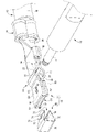
- FIG. 1 is a perspective view showing a female terminal according to the first embodiment in a state where a male terminal is inserted.
- FIG. 2 is an exploded perspective view of the female terminal shown in FIG.
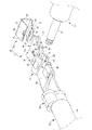
- FIG. 3 is an exploded perspective view of the female terminal shown in FIG. 1 from another angle.
- FIG. 4 is an exploded perspective view of the female terminal shown in FIG. 1 from yet another angle.
- FIG. 5 is a sectional view taken along line VV in FIG.
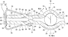
- FIG. 6 is a sectional view taken along line VI-VI in FIG.
- FIG. 7A is an explanatory diagram for modeling a state in which an elastic member is attached to the female terminal fitting.
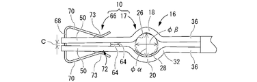
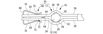
- FIG. 7B is an explanatory diagram for modelably explaining the initial state of the female terminal in which the elastic member is attached to the female terminal fitting.
- FIG. 7A is an explanatory diagram for modeling a state in which an elastic member is attached to the female terminal fitting.
- FIG. 7B is an explanatory diagram for modelably explaining the initial state of
- FIG. 7C is an explanatory diagram for explaining a state in which the male terminal is inserted into the female terminal as a model.
- FIG. 7D is an explanatory diagram for modeling a state in which the tips of the female terminal fittings are close to each other due to stress relaxation due to changes over time.
- FIG. 8A is an explanatory diagram for explaining a state when the male terminal is inserted into the female terminal as a model, and is a diagram showing the female terminal and the male terminal in a cross section of VIIIA-VIIIA in FIG.
- FIG. 8B is an explanatory diagram for modeling a state immediately after inserting the male terminal into the female terminal, and is a diagram showing the female terminal and the male terminal in the same cross section as in FIG. 8A.
- FIG. 8C is an explanatory diagram for modeling a state in which the male terminal is being inserted into the female terminal, and is a diagram showing the female terminal and the male terminal in the same cross section as in FIG. 8A.
- the female terminal of the present disclosure is (1) A cylindrical connection portion that includes a first peripheral wall portion and a second peripheral wall portion that are arranged so as to face each other and is electrically connected to a columnar connection portion of a male terminal, and the first peripheral wall portion and the first peripheral wall portion.
- a pair of tip side plate portions that are separated from each other from a pair of peripheral end portions facing each other of the two peripheral wall portions, project outward in the radial direction of the cylindrical connection portion, and can be flexed and deformed in a direction approaching each other.
- the pair of elastic members that urge the pair of tip side plates in a direction approaching each other to exert an urging force in an approaching direction to the first peripheral wall portion and the second peripheral wall portion in a mutually approaching direction. It has a stopper portion provided on at least one of the pair of facing surfaces of the tip side plate portion and projecting toward the other facing surface, and the stopper portion is from the tip portion of the pair of tip side plate portions. Is also provided at a position close to the cylindrical connection portion, and by abutting on the other facing surface, the displacement of the pair of tip side plate portions in the approach direction is limited, and the tips of the pair of tip side plate portions are limited.
- the portions are maintained in a separated state, and the pair of tip side plate portions and the first peripheral wall portion and the second peripheral wall portion are separated and displaced in the direction opposite to the approaching direction against the urging force of the elastic member. This allows the male terminal to be inserted into the cylindrical connection portion of the columnar connection portion.
- the cylindrical connection portion that is electrically connected to the columnar connection portion of the male terminal is configured to include the first peripheral wall portion and the second peripheral wall portion that are arranged so as to face each other.
- a pair of tip side plate portions protruding radially outward from each peripheral end portion of the first peripheral wall portion and the second peripheral wall portion are separated from each other.
- the pair of tip side plates are urged by elastic members in a direction in which they approach each other. As a result, it is possible to exert an urging force in the approaching direction that approaches each other with respect to the first peripheral wall portion and the second peripheral wall portion.
- the tip side plate portion is provided with a stopper portion located closer to the cylindrical connection portion than the tip portion, and the displacement of the pair of tip side plate portions in the approach direction due to the urging force of the elastic member is restricted. , The tips of the pair of tip side plates are maintained in a separated state. Therefore, as the tips of the pair of tip side plates are separated from each other, the facing gap between the first peripheral wall portion and the second peripheral wall portion of the tubular connection portion before the columnar connection portion of the male terminal is inserted is compared. It is possible to secure a large size, and it is also possible to reduce the insertion resistance of the columnar connection portion of the male terminal into the cylindrical connection portion of the female terminal.
- the tips of the pair of tip side plates are separated from each other by the stopper before the columnar connection of the male terminal is inserted, the pair of tips after the columnar connection of the male terminal is inserted. It is possible to secure a large separation distance between the tips of the side plates. As a result, it is possible to prevent the tips of the pair of tip side plates from coming into contact with each other due to stress relaxation due to aging of the material of the pair of tip side plates. As a result, it is possible to suppress or prevent a problem that the urging force of the elastic member is dispersed on the tip side of the pair of tip side plate portions and the contact pressure of the cylindrical connection portion with the columnar connection portion is reduced.
- the stopper portion is provided on the cylindrical connection portion side with respect to the tip portion of the tip side plate portion. Therefore, it is less susceptible to stress relaxation due to aging of the material of the pair of tip side plates than the tip, and it is possible to prevent the stoppers from coming into contact with each other due to the stress relaxation of the pair of tip side plates.
- the stopper portion is provided on the cylindrical connection portion side of the portion where the urging force of the elastic member is applied to the pair of tip side plate portions. Since the stopper portion is closer to the cylindrical connection portion than the portion where the urging force of the elastic member is applied to the pair of tip side plate portions, it is less susceptible to the displacement due to stress relaxation of the material of the female terminal. Therefore, the contact between the stopper portions can be advantageously suppressed, and the machining dimensional tolerance of the stopper portions can be set to be small to secure a larger inner diameter of the cylindrical connection portion.
- At least one of the first peripheral wall portion and the second peripheral wall portion has a contact portion protruding inward in the radial direction, and in the tubular connection portion, the cylinder of the columnar connection portion of the male terminal.
- the inner diameter dimension is larger than the diameter dimension of the columnar connection portion, and at the formation portion of the contact portion, the inner diameter dimension is smaller than the diameter dimension of the columnar connection portion. , Is preferred.
- the stopper part limits the displacement of the tip side plates in the approaching direction, and the tips of the pair of tip side plates can be stably maintained in a separated state. Therefore, in order to increase the separation distance between the tips of the pair of tip side plates, it is necessary to project the pair of tip side plates outward in the radial direction so that the facing gap increases toward each tip. It gets lower. As a result, the tip portions of the pair of tip side plate portions can be maintained in a separated state while ensuring a large inner diameter dimension of the tubular connecting portion, which is the radial facing distance between the first peripheral wall portion and the second peripheral wall portion.
- the inner diameter of the cylindrical connection portion is made smaller than the diameter dimension of the columnar connection portion at the contact portion forming portion, and the columnar connection portion is secured while ensuring the contact pressure between the columnar connection portion and the cylindrical connection portion.
- the inner diameter dimension of the tubular connection portion can be made larger than the diameter dimension of the columnar connection portion. Therefore, it is not necessary to press-fit the columnar connection portion into the tubular connection portion until the columnar connection portion of the male terminal abuts on the contact portion, and the insertion force of the male terminal into the female terminal can be reduced.
- both the first peripheral wall portion and the second peripheral wall portion have an inner surface having an arc-shaped cross section, and one of the first peripheral wall portion and the second peripheral wall portion has an inner surface. It is preferable that an arc-shaped protrusion extending in the circumferential direction of the inner surface is provided, and the contact portion is formed by the arc-shaped protrusion. Both the first peripheral wall portion and the second peripheral wall portion have an inner surface having an arcuate cross section, and one inner surface is provided with an arcuate protrusion extending in the circumferential direction of the inner surface.
- the arcuate protrusion can be pressed into a wide range of the outer peripheral surface of the columnar connection portion of the male terminal pressed into the tubular connection portion of the female terminal with high contact pressure, and the contact area between the male and female terminals is widened. It can be secured stably.
- a linear contact portion extending in the axial direction of the cylindrical connection portion is separated in the circumferential direction on the inner surface of the other of the first peripheral wall portion and the second peripheral wall portion. It is preferable that the contact portion is provided at a plurality of locations and the contact portion is formed by the linear contact portion. On the other inner surface of the first peripheral wall portion and the second peripheral wall portion, linear contact portions extending in the axial direction of the tubular connecting portion are provided at a plurality of locations separated in the circumferential direction. Thereby, even when the swing is transmitted from the electric wire to the male terminal, the swing displacement of the male terminal can be prevented by the contact of the male terminal with the plurality of linear contact portions.
- the first peripheral wall portion and the second peripheral wall portion are pressed against a wide range of the outer peripheral surface of the columnar connection portion of the male terminal with high contact pressure by the arcuate protrusion portion of one of the first peripheral wall portion and the second peripheral wall portion.
- the rocking displacement of the male terminal can be prevented by the other plurality of linear contact portions of the portion, and both the increase in the contact area with the male terminal and the stable holding of the male terminal can be achieved at the same time.
- the elastic member has a connecting plate and a pair of holding pieces that project from both ends of the connecting plate to one side in the plate thickness direction of the connecting plate and incline in a direction approaching each other. It is preferable that the elastic member is assembled to the pair of tip side plates with the tip of the pair of tip side plates sandwiched between the pair of holding pieces.
- the elastic member can be manufactured with a simple structure, and the male and female terminals can be stably held in the connected state. Moreover, since the elastic member is assembled to the pair of tip side plates with the tip of the pair of tip side plates sandwiched between the pair of holding pieces, the elastic member can be assembled without increasing the size of the female terminal. Can be provided.
- the female terminal 10 of the first embodiment of the present disclosure will be described with reference to FIGS. 1 to 8C.
- the female terminal 10 includes a cylindrical connection portion 16 that is electrically connected to the columnar connection portion 14 of the male terminal 12. Then, the columnar connection portion 14 of the male terminal 12 is inserted into the cylindrical connection portion 16 of the female terminal 10, and the inner surface of the tubular connection portion 16 and the outer surface of the columnar connection portion 14 come into mutual contact with each other, whereby the female terminal is formed.
- the 10 and the male terminal 12 are electrically connected to each other.
- the male terminal 12 is not limited as long as it includes the columnar connection portion 14, and the end portion of the male terminal 12 opposite to the columnar connection portion 14 is fixed to the terminal portion of the device with, for example, a bolt or the like. It may be fixed to an electric wire.
- the front means the left side in FIG. 5, and the rear means the right side in FIG.
- the upper part means the upper part in FIG. 5, and the lower part means the lower part in FIG.
- the left side means the left side in FIG. 6, and the right side means the right side in FIG.
- a reference numeral may be added to only a part of the members, and the reference numeral may be omitted for other members.
- the female terminal 10 is configured by assembling a clip spring 66 as an elastic member, which will be described later, to the female terminal fitting 17.
- the female terminal fitting 17 is formed by pressing a metal flat plate having a substantially strip shape as a whole into a predetermined shape.
- the metal constituting the metal flat plate copper, a copper alloy, aluminum, an aluminum alloy or the like having low electric resistance can be adopted.
- the female terminal fitting 17 includes the above-mentioned cylindrical connection portion 16.
- the tubular connecting portion 16 has a substantially cylindrical shape as a whole, and is open on both sides in the left-right direction. That is, the axial direction of the tubular connecting portion 16 is the left-right direction.
- the tubular connecting portion 16 includes a first peripheral wall portion 18 and a second peripheral wall portion 20 which are arranged so as to face each other in the vertical direction.
- the first peripheral wall portion 18 is located on the upper side and the second peripheral wall portion 20 is located on the lower side.
- the first peripheral wall portion 18 and the second peripheral wall portion 20 are substantially half-divided cylindrical bodies, respectively, and have inner surfaces 22 and 24 having an arcuate cross section in the vertical cross section of the female terminal 10 shown in FIG. 5, respectively. There is.
- the first peripheral wall portion 18 has a constant cross-sectional shape over the entire length in the axial direction (left-right direction).
- the inner surface 22 of the first peripheral wall portion 18 may be a curved surface having a substantially constant curvature, but in the first embodiment, the inner surface 22 of the first peripheral wall portion 18 has a partially different curvature in the circumferential direction.
- portions having a curvature smaller than that of the central portion in the circumferential direction are provided at two locations separated from the central portion in the circumferential direction on both ends in the circumferential direction.
- the central portion of the inner surface 22 in the circumferential direction has an arc shape having a substantially constant curvature, and both ends of the arc in the circumferential direction extend substantially linearly.
- the parts are connected.
- the two locations separated from the central portion in the circumferential direction to both ends in the circumferential direction project inward in the radial direction.
- the inner surface 22 of the first peripheral wall portion 18 is separated from the central portion in the circumferential direction on both ends in the circumferential direction. It comes into contact with the outer surface of the columnar connecting portion 14. Since the first peripheral wall portion 18 extends in the axial direction with a constant cross-sectional shape, the first peripheral wall portion 18 and the columnar connecting portion 14 are separated from the central portion in the circumferential direction on both ends in the circumferential direction. , Contact in the form of line contact.
- the linear contact portion 26 constitutes an upper contact portion with the columnar connection portion 14. That is, on the inner surface 22 of the first peripheral wall portion 18 as the other inner surface, a linear contact portion 26 as a contact portion that extends inward in the radial direction while extending in the axial direction of the tubular connection portion 16 is provided in the circumferential direction. It is provided at a plurality of places (two places) separated from each other. Therefore, in the first embodiment, when the columnar connecting portion 14 is inserted into the tubular connecting portion 16, the central portion in the circumferential direction of the inner surface 22 and the outer surface of the columnar connecting portion 14 do not come into contact with each other.
- an arcuate protrusion 28 is provided at the central portion in the axial direction (left-right direction) so as to extend in the circumferential direction of the inner surface 24 and project inward in the radial direction.
- the arcuate protrusion 28 is formed at the central portion of the inner surface 24 in the circumferential direction with a predetermined width direction dimension (left-right direction dimension) and a predetermined circumferential direction dimension.
- the arcuate protrusion 28 is formed by pressing the second peripheral wall portion 20 at a position corresponding to the arcuate protrusion 28 on the outer surface of the second peripheral wall portion 20.
- a recess 30 that opens outward (downward) is formed.
- the arcuate protrusion 28 and the outer surface of the columnar connection portion 14 come into contact with each other, and the arcuate protrusion 28 causes the columnar connection portion 14 to come into contact with the columnar connection portion 14.
- the lower contact part is configured.
- the curvature of the inner surface of the arcuate protrusion 28 is smaller than the curvature of the outer surface of the columnar connection portion 14, and in particular, the center of the inner surface of the arcuate protrusion 28 in the circumferential direction is the columnar connection portion. It is a lower contact portion with 14.
- the arcuate protrusion 28 protrudes most radially inward in the center in the left-right direction, and when the columnar connection portion 14 is inserted into the tubular connection portion 16, it is a circle.
- the center of the arcuate protrusion 28 in the left-right direction and the outer surface of the columnar connection portion 14 come into contact with each other. Therefore, of the inner surface of the arcuate protrusion 28, the center in the left-right direction is the lower contact portion with the columnar connecting portion 14.
- both sides sandwiching the center in the left-right direction are curved surfaces 31 and 31 that gradually bend and project inward in the radial direction of the tubular connecting portion 16 as they become inward in the left-right direction.
- the inner diameter ⁇ (see FIGS. 7B and 8A) of the tubular connection portion 16 is the male terminal 12.
- the outer diameter of the columnar connection portion 14 is substantially equal to or slightly larger than the outer diameter dimension ⁇ (see FIG. 8A).
- the inner diameter ⁇ (see FIGS. 7B and 8A) at the contact portion of the tubular connection portion 16 is a columnar connection in the male terminal 12. It is slightly smaller than the outer diameter dimension ⁇ of the portion 14.
- the inner diameter dimension ⁇ is columnar at the front end (right side) of the columnar connection portion 14 in the insertion direction (direction from right to left) into the tubular connection portion 16.
- the outer diameter of the connecting portion 14 is substantially equal to or slightly larger than the outer diameter dimension ⁇ .
- the inner diameter dimension ⁇ is slightly smaller than the outer diameter dimension ⁇ of the columnar connection portion 14 at the contact portion forming portion.
- the peripheral end portions facing each other in the vertical direction are the first peripheral end portions 32 and 32, respectively.
- the pair of first peripheral end portions 32, 32 face each other with a predetermined separation distance in the vertical direction.
- the peripheral end portions facing each other in the vertical direction are the second peripheral end portions 34 and 34 as peripheral end portions, respectively.
- the pair of second peripheral end portions 34, 34 face each other with a predetermined separation distance in the vertical direction.
- the pair of first peripheral end portions 32, 32 are provided with a pair of base end side plate portions 36, 36 that project outward (rearward) in the radial direction of the cylindrical connection portion 16, respectively.
- the female terminal fitting 17 is formed by pressing a metal flat plate having a substantially strip shape, and the pair of base end side plate portions 36, 36 are rear portions of the base end side plate portions 36, 36. Are connected to each other.
- the pair of base end side plate portions 36, 36 have a substantially rectangular shape in the vertical direction, respectively.
- the upper and lower base end side plate portions 36, 36 are connected to each other by a connecting portion 38 provided on the left side at the rear end portion, and are connected to the right side at the rear end portion of the upper base end side plate portion 36.
- a caulking piece 40 is provided.
- the caulking piece 40 is bent, so that the lower base end side plate portion 36 becomes the upper base as shown in FIG. It is designed to be caulked and fixed to the end side plate portion 36.
- the upper and lower base end side plate portions 36, 36 are prevented from being displaced in the direction of being separated from each other.
- a wire crimping portion 44 to which the wire 42 is crimped is provided in a portion behind the base end side plate portions 36, 36.
- the electric wire 42 is a coated electric wire, and the core wire 46 is covered with an insulating coating 48.
- the core wire 46 exposed by peeling off the insulating coating 48 at the end of the electric wire 42 is crimped to the electric wire crimping portion 44 provided at the rear end of the female terminal 10 (female terminal fitting 17).
- the method of fixing the core wire 46 to the female terminal 10 (female terminal fitting 17) is not limited to crimping, and may be, for example, adhesion or welding.
- the female terminal 10 may be fixed to the terminal portion of the device with a bolt or the like instead of the electric wire 42.
- the pair of second peripheral end portions 34, 34 are provided with a pair of tip side plate portions 50, 50 protruding outward (forward) in the radial direction of the cylindrical connection portion 16, respectively.
- the pair of tip side plate portions 50, 50 have a substantially rectangular shape in the vertical direction, and are separated from each other in the vertical direction. That is, in the female terminal 10, the base end side plate portions 36, 36 are connected to each other on one side in the front-rear direction with respect to the first peripheral wall portion 18 and the second peripheral wall portion 20, and the first peripheral wall portion 18 and the first peripheral wall portion 18 are connected to each other.
- the tip side plate portions 50, 50 are separated from each other on the other side in the front-rear direction with respect to the two peripheral wall portions 20, and form a free end protruding like a cantilever. As a result, the tip side plate portions 50, 50 can be flexed and deformed in the direction of approaching each other.
- positioning protrusions 52, 52 projecting forward are provided on both sides in the left-right direction.
- the left-right intermediate portion is located behind the positioning protrusions 52, 52.
- a clip spring mounting portion 54 to which a clip spring 66 described later is mounted is configured at an intermediate portion in the left-right direction at the front end portions of the tip side plate portions 50, 50.
- each convex portion 56 has a substantially triangular shape or a substantially trapezoidal shape in a left-right direction view, the rear surface of each convex portion 56 is a vertical surface 58 extending substantially in the vertical direction, and the front surface of each convex portion 56 is forward.
- the inclined surface 60 is inclined so that the height of protrusion in the vertical direction becomes smaller.
- the stopper portions 64, 64 are provided at the central portions in the width direction on both of the pair of facing surfaces 62, 62, and each protrudes inward in the vertical direction and faces each other.
- Each stopper portion 64 is provided at a position closer to the cylindrical connecting portion 16 than the tip portions of the pair of tip side plate portions 50, 50.
- each stopper portion 64 is provided behind the convex portion 56 provided on the outer surface of the tip side plate portion 50 (on the cylindrical connection portion 16 side).
- These stopper portions 64, 64 are formed by pressing the tip side plate portions 50, 50, and are vertically located at positions corresponding to the stopper portions 64, 64 on the outer surface of the tip side plate portions 50, 50.
- Recesses 65, 65 that open outward in the direction are formed.
- each stopper portion 64 has a flat substantially cylindrical shape in which the height dimension (vertical dimension) is smaller than the outer diameter dimension.
- the protrusion height dimension of each of these stopper portions 64 is smaller than 1/2 of the facing distance of the facing surfaces 62 and 62.
- the tip portions of the pair of tip side plate portions 50, 50 are maintained in a separated state.
- the stopper portions 64, 64 are provided on both of the pair of facing surfaces 62, 62 of the pair of tip side plate portions 50, 50, when the clip spring 66 is attached to the female terminal fitting 17.
- the stopper portions 64 and 64 are in contact with each other, and one of the stopper portions 64 is indirectly in contact with the opposite tip side plate portion 50.
- ⁇ Clip spring 66> At the front end portions of the tip side plate portions 50, 50, the first peripheral wall portions 18 and the first peripheral wall portion 18 connected to the rear of the tip side plate portions 50, 50 by urging the tip side plate portions 50, 50 in a direction approaching each other.
- a clip spring 66 is attached as an elastic member that exerts a urging force in an approaching direction that approaches each other with respect to the peripheral wall portion 20.
- the clip spring 66 is formed by using various metal materials that can be pressed, punched, etc., for example, strips of spring steel, stainless steel, brass, phosphor bronze, beryllium copper, and the like.
- the clip spring 66 projects from both ends of the connecting plate 68 having a substantially rectangular shape in the front-rear direction toward one side (rear in FIG. 5) of the connecting plate 68 in the plate thickness direction and approaches each other. It has a pair of holding pieces 70, 70 that are inclined to. Bending portions 73, 73 are provided at the intermediate portion in the length direction of the holding pieces 70, 70, and the protruding tip portions of the holding pieces 70, 70 extend in a direction away from the bending portions 73, 73. There is. Therefore, the facing distance between the holding pieces 70 and 70 is the smallest in the bent portions 73 and 73 provided in the intermediate portion in the length direction, and the gap between the bent portions 73 and 73 is set with respect to the clip spring 66.
- the minimum opening size A of the insertion port 72 of the clip spring 66 in the single item state before being attached to the female terminal metal fitting 17 is larger than the vertical dimension B of the female terminal metal fitting 17 in the single item state. It has been made smaller.
- a substantially rectangular locking recess 74 that penetrates the presser piece 70 in the plate thickness direction is formed at the center of the bent portions 73, 73 of the pair of presser pieces 70, 70 in the width direction.
- the clip spring 66 having the above shape is assembled from the front of the pair of tip side plate portions 50, 50. That is, the tip side plate portions 50, 50 of the female terminal fitting 17 are inserted into the insertion port 72 of the clip spring 66, and the clip spring 66 is slid rearward with respect to the female terminal fitting 17. As a result, the pair of holding pieces 70, 70 in the clip spring 66 sandwich the tip side plate portions 50, 50 of the female terminal fitting 17 from the outside in the vertical direction. Then, each convex portion 56 protruding outward in the vertical direction from the tip side plate portions 50, 50 is locked to each locking recess 74 in the clip spring 66. As a result, the clip spring 66 is assembled to the pair of tip side plate portions 50, 50 with the tip portions (front end portions) of the pair of tip side plate portions 50, 50 sandwiched between the pair of holding pieces 70, 70. ing.
- each convex portion 56 is an inclined surface 60 and the protruding tip portions of the holding pieces 70 and 70 are inclined in a direction in which they are separated from each other, the protruding tip portions of the holding pieces 70 and 70 are respectively.
- the convex portion 56 can be easily overcome.
- each locking recess 74 is stably locked by the vertical surface 58 which is the rear surface of each convex portion 56.
- the clip spring mounting portion 54 is provided at the intermediate portion in the left-right direction at the front end portion of the female terminal fitting 17.
- the tip side plate portions 50 and 50 are provided on both left and right sides of the connecting plate 68 in the left-right direction.
- the positioning protrusions 52 and 52 are positioned.
- the pair of holding pieces 70, 70 of the clip spring 66 are provided with bending portions 73, 73 that define the minimum opening dimension A of the insertion port 72 of the clip spring 66.
- the minimum opening dimension A of the insertion port 72 which is the facing gap between the bent portions 73, 73, is smaller than the vertical dimension B of the female terminal fitting 17 (tip side plate portions 50, 50). Therefore, when the clip spring 66 is attached to the front end portion of the tip side plate portions 50, 50, the tip side plate portions 50, 50 push the insertion port 72 of the female terminal fitting 17 outward in the vertical direction to press the presser.
- the pieces 70 and 70 are elastically deformed in the direction in which they are separated from each other.
- the clip spring 66 is assembled to the front end portions of the tip side plate portions 50, 50.
- the elastic restoring force of these holding pieces 70, 70 is exerted as an urging force in the direction of approaching each other with respect to the front end portions of the tip side plate portions 50, 50. That is, the portion of the tip side plate portions 50, 50 that abuts on the bent portion 73 of each holding piece 70 in the clip spring 66 is the portion where the urging force is applied by the clip spring 66.
- the locking recesses 74 and 74 are provided in the bent portions 73 and 73 in the holding pieces 70 and 70 of the clip spring 66, the locking recesses 74 and 74 are engaged in the tip side plate portions 50 and 50.
- the formed portions of the convex portions 56 and 56 to be stopped are the portions where the urging force is applied by the clip spring 66.
- first peripheral wall portion 18 and the second peripheral wall portion 20 connected to the rear of the distal end side plate portions 50, 50 by exerting an urging force on the distal end side plate portions 50, 50 in a direction in which they approach each other.
- the second peripheral end portions 34, 34 are urged in a direction approaching each other.
- the tip side plate resists the urging force of the holding pieces 70, 70.
- the portions 50, 50 and the first and second peripheral wall portions 18, 20 are displaced in a direction in which they are separated from each other.
- FIG. 7A shows a method of connecting the male terminal 12 and the female terminal 10 by inserting the columnar connection portion 14 of the male terminal 12 into the cylindrical connection portion 16 of the female terminal 10 having the above-mentioned shape.
- FIG. 8C will be shown and described as a model.
- the clip spring 66 is assembled from the front to the tip side plate portions 50, 50 of the female terminal fitting 17.
- the female terminal 10 is completed as shown in FIG. 7B.
- the clip spring 66 is in the direction of approaching each other with respect to the tip side plate portions 50, 50 and the second peripheral end portions 34, 34. Enforcement is exerted. According to this urging force, the tip side plate portions 50, 50 are displaced in the direction of approaching each other, and the stopper portions 64, 64 provided on the facing surfaces 62, 62 of the tip side plate portions 50, 50 abut on each other. In the contact state of both stopper portions 64, 64 shown in FIG.
- the tip portions of the tip side plate portions 50, 50 are separated from each other with a predetermined separation distance C. Therefore, the stopper portions 64, 64 are in contact with each other to limit the displacement of the pair of tip side plate portions 50, 50 in the approaching direction, so that the tip portions of the pair of tip side plate portions 50, 50 are separated from each other. It is designed to be maintained.
- the second peripheral end portions 34, 34 of the first peripheral wall portion 18 and the second peripheral wall portion 20 are displaced in the direction of approaching each other, so that the state shown in FIG. 7B (female terminal before insertion of the male terminal 12) is obtained.
- the inner diameter dimension of the tubular connection portion 16 in the initial state of 10) is slightly smaller than the inner diameter dimension of the tubular connection portion 16 in the state shown in FIG. 7A.
- the inner diameter dimension of the tubular connection portion 16 is ⁇ . ..
- the inner diameter of the contact portion (linear contact portion 26, 26 and arcuate protrusion 28) provided in the tubular connection portion 16 is virtual.
- the inner diameter of the circle) is ⁇ .
- the inner diameter dimension ⁇ of the tubular connection portion 16 in the state shown in FIG. 7B is substantially equal to or slightly larger than the outer diameter dimension ⁇ of the columnar connection portion 14 in the male terminal 12.
- the inner diameter dimension ⁇ at the contact portion of the tubular connecting portion 16 is slightly smaller than the outer diameter dimension ⁇ of the columnar connecting portion 14 at the male terminal 12.
- the columnar connection portion 14 of the male terminal 12 is inserted into the cylindrical connection portion 16 of the female terminal 10 having the above-mentioned shape.
- the inner diameter dimension ⁇ at the contact portion of the tubular connecting portion 16 is slightly smaller than the outer diameter dimension ⁇ of the columnar connecting portion 14. Therefore, immediately after inserting the columnar connection portion 14 into the tubular connection portion 16, the contact portion (line) in the tubular connection portion 16 is on the front side (right side) in the insertion direction (direction from right to left).
- the shaped contact portions 26, 26 and the arcuate protrusion 28) are in contact with the outer surface of the columnar connecting portion 14.
- the columnar connection portion 14 by further inserting the columnar connection portion 14 into the tubular connection portion 16, the inner surface of the tubular connection portion 16 is expanded by the outer surface of the columnar connection portion 14, and the first peripheral wall portion 18 and the second peripheral wall portion 18 are further expanded.
- An external force is applied to the portion 20 in the vertical direction and outward.
- the first peripheral wall portion 18 and the second peripheral wall portion 20 are separated and displaced in the direction opposite to the direction in which they approach each other against the urging force of the holding pieces 70 and 70 of the clip spring 66.
- the columnar connecting portion 14 can be inserted into the cylindrical connecting portion 16 in a press-fitted state.
- the contact portions (linear contact portions 26, 26 and arcuate protrusion 28) in the tubular connection portion 16 come into contact with the intermediate portion in the length direction of the columnar connection portion 14, so that the cylindrical connection portion 16 is contacted.
- the columnar connection portion 14 is held, and the male terminal 12 and the female terminal 10 are electrically connected.
- the tip portions of the tip side plate portions 50 and 50 are displaced in the direction of approaching each other due to stress relaxation.
- the stopper portions 64, 64 it is possible to secure a large separation distance D at the tip portions of the tip side plate portions 50, 50 in FIG. 7C. Therefore, even if the tip portions of the tip side plate portions 50 and 50 are displaced in the direction of approaching each other, it is possible to advantageously avoid contact between the tip portions of the tip side plate portions 50 and 50 as shown in FIG. 7D. ..
- the holding pieces 70 and 70 of the clip spring 66 are used in the vertical direction in the first peripheral wall portion 18 and the second peripheral wall portion 20. An inward urging force is applied, and the columnar connecting portion 14 is inserted into the tubular connecting portion 16 in a press-fitted state. As a result, it is possible to improve the contact pressure between the cylindrical connection portion 16 and the columnar connection portion 14.
- the female terminal 10 is provided with stopper portions 64, 64 facing each other in the tip side plate portions 50, 50 facing each other in the vertical direction.
- both stopper portions 64 and 64 come into contact with each other.
- the displacement of the tip side plate portions 50, 50 and the second peripheral end portions 34, 34 in the opposite direction is limited, and for example, the stopper portion is not provided and the tip portions of the tip side plate portions are attached to each other when the clip spring is attached.
- the inner diameters ⁇ and ⁇ in the tubular connection portion 16 become smaller than necessary as compared with the case where the two are in contact with each other. Therefore, even when the columnar connecting portion 14 is inserted into the tubular connecting portion 16 in a press-fitted state, the insertion resistance force can be suppressed to a small value.
- the tip portions of the tip side plate portions 50, 50 are separated from each other with a predetermined separation distance C in the initial state of the female terminal 10 shown in FIG. 7B. Can be made to.
- the tip portions of the tip side plate portions 50 and 50 can be separated from each other with a larger separation distance D. Therefore, as shown in FIG. 7D, even if stress relaxation occurs due to aging, the tips of the tip side plates 50 and 50 do not come into contact with each other, and the clip spring 66 is attached by the holding pieces 70 and 70.
- the force is stably applied to the first peripheral wall portion 18 and the second peripheral wall portion 20. As a result, even if the connection state between the male terminal 12 and the female terminal 10 continues for a long period of time, the connection state between the male terminal 12 and the female terminal 10 is stably maintained.
- the facing gap between the tip side plate portions 50, 50 gradually increases toward the tip portion without providing the stopper portions 64, 64. Therefore, it is conceivable to change the projecting angle of the tip side plate portions 50, 50 in the radial direction.
- the inner diameter dimensions ⁇ and ⁇ of the cylindrical connection portion 16 are smaller than those in the case of the first embodiment. As a result, the insertion resistance force when the columnar connection portion 14 of the male terminal 12 is inserted into the tubular connection portion 16 becomes large, which is not preferable.
- the separation distance C between the tip portions of the tip side plate portions 50 and 50 is made larger than 0 when the clip spring 66 shown in FIG. 7B is attached. be able to. Therefore, it is possible to achieve both the effect of maintaining the connection state between the male terminal 12 and the female terminal 10 at the time of stress relaxation and the effect of reducing the insertion resistance of the male terminal 12 into the female terminal 10.
- the stopper portions 64, 64 are provided on the cylindrical connection portion 16 side of the tip side plate portions 50, 50 with respect to the portion where the urging force is applied by the clip spring 66 (the portion where the convex portions 56, 56 are formed). As a result, even when the tips of the tip side plates 50 and 50 approach each other due to stress relaxation, for example, the displacement amount of the tip side plates 50 and 50 at the formed portions of the stoppers 64 and 64 is larger than that of the tip. Be made smaller. Further, for example, as compared with the case where the stopper portion 64 is provided at the tip portion of the tip side plate portion 50, the substantially strip-shaped metal flat plate constituting the female terminal fitting 17 is bent to form the first peripheral wall portion 18 and the second peripheral wall portion.
- the tolerance in the stopper portion 64 can be reduced. As a result, it is possible to more reliably avoid contact between the tip portions of the tip end side plate portions 50, 50 when stress relaxation occurs. As a result, the urging force of the clip spring 66 is not dispersed due to the contact between the stopper portions 64 and 64, and is stably applied to the first peripheral wall portion 18 and the second peripheral wall portion 20. Therefore, the connection state between the male terminal 12 and the female terminal 10 is stably maintained.
- the inner diameter dimension ⁇ of the cylindrical connection portion 16 is substantially equal to or slightly equal to the outer diameter dimension ⁇ of the columnar connection portion 14 on the front side in the insertion direction of the male terminal 12. It has been enlarged. Further, the inner diameter dimension ⁇ at the contact portion of the tubular connecting portion 16 is slightly smaller than the outer diameter dimension ⁇ of the columnar connecting portion 14. As a result, for example, when the columnar connection portion 14 is inserted into the cylindrical connection portion 16, the outer surface of the columnar connection portion and the inner surface of the tubular peripheral wall portion do not come into contact with each other over substantially the entire surface, and the tubular connection portion 16 does not come into contact with each other.
- an arcuate protrusion 28 extending in the circumferential direction is provided on the inner surface 24 of the second peripheral wall portion 20.
- the outer surface of the columnar connecting portion 14 and the inner surface 24 of the second peripheral wall portion 20 can be brought into contact with each other with a relatively large contact area.
- linear contact portions 26, 26 extending in the axial direction of the tubular connecting portion 16 are provided on the inner surface 22 of the first peripheral wall portion 18.
- the lower contact portion is provided at the central portion in the circumferential direction of the inner surface 24 of the second peripheral wall portion 20, and the upper contact portion is the inner surface 22 of the first peripheral wall portion 18. It is provided at two locations separated from the central portion in the circumferential direction on both ends in the circumferential direction.
- the columnar connection portion 14 can be supported at three points on the circumference on the inner surface of the tubular connection portion 16, and the connection state between the male terminal 12 and the female terminal 10 is stably maintained.
- the arcuate protrusion 28, which is the lower contact portion of the cylindrical connection portion 16 has a curved surface 31 on the front side (right side) of the male terminal 12 in the insertion direction. Therefore, the insertion resistance when the male terminal 12 is inserted into the female terminal 10 can be reduced, and the effect of preventing plating scraping can be further exhibited.
- the elastic member that exerts an urging force in the direction of mutually approaching the tips of the tip side plate portions 50 and 50 is composed of a clip spring 66 having a connecting plate 68 and holding pieces 70 and 70. Thereby, the elastic member can be constructed with a simple structure.
- the stopper portions 64 and 64 are provided on both of the pair of facing surfaces 62 and 62 of the pair of tip side plate portions 50 and 50, but the stopper portion is opposed to one of the tip side plate portions. It may be provided on the surface and project toward the facing surface of the other end side plate portion. In that case, the stopper portion abuts on the other tip side plate portion when the clip spring is attached to the female terminal fitting, and does not abut on the other tip side plate portion when the male terminal is inserted or stress is relaxed. Just do it.
- the stopper portions 64, 64 are located closer to the cylindrical connection portion 16 than the portion where the urging force is applied by the clip spring 66 (the portion where the convex portions 56, 56 are formed) in the tip side plate portions 50, 50.
- the stopper portions 64, 64 are provided at a portion where the female terminal 10 is located and is not easily affected by displacement due to stress relaxation of the material of the female terminal 10, but the present invention is not limited to this embodiment.
- the stopper part should be in contact with the opposite tip side plate or stopper when the clip spring is attached to the female terminal fitting, and should not be in contact with the opposite tip side plate or stopper when the male terminal is inserted or stress is relaxed. As long as it is closer to the tubular connection portion than the tip portion, the arrangement position of the stopper portion on the tip side plate portion is not limited.
- the shape of the contact portion of the columnar connection portion to the outer surface is not limited to that described in the above embodiment.
- a contact portion protruding inward in the radial direction may be provided on one inner surface.
- a linear contact portion may be provided on both inner surfaces, or the first peripheral wall portion may be provided.
- An arcuate protrusion may be provided on both inner surfaces of the second peripheral wall portion and the second peripheral wall portion.
- the linear contact portion may be provided at one location on the circumference on the inner surface of the first peripheral wall portion or the second peripheral wall portion, or may be separated from each other in the circumferential direction at three or more locations on the circumference. It may be provided.
- the linear contact portion and the arc-shaped protrusion are not essential.
- the columnar connection portion 14 of the male terminal 12 is inserted from the right side to the left side with respect to the cylindrical connection portion 16 of the female terminal 10, but the columnar connection portion 14 is inserted from the left side to the right side. May be inserted.
- the stopper portions 64 and 64 each have a flat substantially cylindrical shape, and when both stopper portions abut, the respective protruding tip surfaces abut in a surface contact manner.
- the shape of the stopper portion is not limited to that described in the above embodiment.
- the stopper portion may have an elliptical shape, for example, in a hemispherical shape or in a vertical projection, or may abut on the opposite tip side plate portion or stopper portion in the form of point contact or line contact.
Landscapes
- Details Of Connecting Devices For Male And Female Coupling (AREA)
Abstract
Description
接続部に押圧されることにより、雄端子と雌端子が接触状態に保持される。そのため、弾性接触片のばね力のみでは、雌雄端子間の接圧を向上させるには限界があった。さらに、弾性接触片の経年変化により雌雄端子間の接圧を安定して保持し難いおそれもあった。
最初に、本開示の実施態様を列記して説明する。
本開示の雌端子は、
(1)相互に対向配置される第1周壁部と第2周壁部を含んで構成されて、雄端子の柱状接続部と導通接続される筒状接続部と、前記第1周壁部と前記第2周壁部の相互に対向する一対の周端部から、相互に離隔して前記筒状接続部の径方向外方に突出して相互に接近する方向で撓み変形可能な一対の先端側板部と、前記一対の先端側板部を相互に接近する方向に付勢して、前記第1周壁部と前記第2周壁部に対して相互に接近する接近方向への付勢力を及ぼす弾性部材と、前記一対の先端側板部の一対の対向面の少なくとも一方に設けられて、他方の前記対向面に向かって突出するストッパ部と、を有し、前記ストッパ部は、前記一対の先端側板部の先端部よりも前記筒状接続部に近い位置に設けられており、他方の前記対向面に当接することで、前記一対の先端側板部の前記接近方向の変位を制限して前記一対の先端側板部の先端部同士を離隔状態に維持し、前記一対の先端側板部同士および前記第1周壁部と前記第2周壁部が、前記弾性部材の付勢力に抗して前記接近方向と反対方向に離隔変位することにより、前記雄端子の前記柱状接続部の前記筒状接続部への挿入が許容される、ものである。
本開示の雌端子の具体例を、以下に図面を参照しつつ説明する。なお、本開示は、これらの例示に限定されるものではなく、特許請求の範囲によって示され、特許請求の範囲と均等の意味および範囲内でのすべての変更が含まれることが意図される。
以下、本開示の実施形態1の雌端子10について、図1から図8Cを用いて説明する。雌端子10は、雄端子12の柱状接続部14と導通接続される筒状接続部16を備えている。そして、雌端子10の筒状接続部16に雄端子12の柱状接続部14が挿入されて、筒状接続部16の内面と柱状接続部14の外面とが相互に接触することで、雌端子10と雄端子12とが電気的に接続されるようになっている。なお、雄端子12は柱状接続部14を備えていれば限定されるものではなく、雄端子12における柱状接続部14と反対側の端部は、例えばボルト等で機器の端子部に固定されてもよいし、電線に固着されてもよい。以下の説明において、前方とは図5中の左方をいい、後方とは図5中の右方をいう。上方とは図5中の上方をいい、下方とは図5中の下方をいう。左方とは図6中の左方をいい、右方とは図6中の右方をいう。また、複数の同一部材については、一部の部材にのみ符号を付し、他の部材については符号を省略する場合がある。
雌端子10は、雌端子金具17に後述する弾性部材としてのクリップばね66が組み付けられることで構成されている。雌端子金具17は、全体として略帯状とされた金属平板を所定の形状にプレス加工することで形成されている。金属平板を構成する金属としては、電気抵抗の低い銅、銅合金、アルミニウム、アルミニウム合金等を採用することができる。雌端子金具17は、前述の筒状接続部16を備えている。
筒状接続部16は、全体として略円筒形状であり、左右方向両側に開口している。すなわち、筒状接続部16の軸方向は左右方向である。筒状接続部16は、上下方向で相互に対向配置される第1周壁部18と第2周壁部20を含んで構成されている。実施形態1では、第1周壁部18が上側に位置しているとともに、第2周壁部20が下側に位置している。第1周壁部18と第2周壁部20は、それぞれ略半割の筒状体であり、図5に示される雌端子10の縦断面において、それぞれ断面円弧形状の内面22,24を有している。したがって、図5にも示されるように、雌端子10の筒状接続部16に雄端子12の柱状接続部14が挿入された際には、柱状接続部14の外面と、第1および第2周壁部18,20の内面22,24とが相互に接触するようになっている。
そして、一対の第1周端部32,32には、それぞれ筒状接続部16の径方向外方(後方)に突出する一対の基端側板部36,36が設けられている。前述のように、雌端子金具17は、略帯状とされた金属平板をプレス加工することによって形成されており、一対の基端側板部36,36は、基端側板部36,36の後方部分で相互に連結されている。一対の基端側板部36,36は、それぞれ上下方向視において略矩形状である。上下の基端側板部36,36は、後端部において、左方に設けられた連結部38により相互に連結されているとともに、上側の基端側板部36の後端部には、右方に突出するかしめ片40が設けられている。これにより、金属平板をプレス加工して雌端子金具17を形成する際に、かしめ片40が折り曲げられることで、図4に示されるように、下側の基端側板部36が、上側の基端側板部36に対してかしめ固定されるようになっている。この結果、プレス加工によって形成された雌端子金具17において上下の基端側板部36,36が、相互に離隔する方向に変位しないようになっている。
一対の第2周端部34,34には、それぞれ筒状接続部16の径方向外方(前方)に突出する一対の先端側板部50,50が設けられている。一対の先端側板部50,50は、それぞれ上下方向視において略矩形状であり、上下方向で相互に離隔している。すなわち、雌端子10においては、第1周壁部18と第2周壁部20に対して前後方向の一方側で基端側板部36,36が相互に連結されており、第1周壁部18と第2周壁部20に対して前後方向の他方側で先端側板部50,50が相互に離隔して片持ち梁状に突出した自由端を構成している。その結果、先端側板部50,50は、相互に接近する方向に撓み変形可能である。それぞれの先端側板部50,50の前端部において、左右方向両側には、前方に突出する位置決め突部52,52が設けられている。換言すれば、先端側板部50,50の前端部において、左右方向中間部分は、位置決め突部52,52よりも後方に位置している。この先端側板部50,50の前端部における左右方向中間部分において、後述するクリップばね66が装着されるクリップばね装着部54が構成されている。
一対の先端側板部50,50の一対の対向面(すなわち、上下方向内面)62,62のうち、少なくとも一方の対向面62には、他方の対向面62に向かって突出するストッパ部64が設けられている。実施形態1では、一対の対向面62,62の両方における幅方向中央部分にストッパ部64,64が設けられており、それぞれ上下方向内方に突出して、相互に対向している。各ストッパ部64は、一対の先端側板部50,50の先端部よりも筒状接続部16に近い位置に設けられている。特に、実施形態1では、各ストッパ部64が、先端側板部50の外面に設けられた凸部56よりも後方(筒状接続部16側)に設けられている。これらストッパ部64,64は、先端側板部50,50に対してプレス加工を施すことにより形成されており、先端側板部50,50の外面においてストッパ部64,64と対応する位置には、上下方向外方に開口する凹部65,65が形成されている。
先端側板部50,50の前端部には、これら先端側板部50,50を相互に接近する方向に付勢して、先端側板部50,50の後方に連結された第1周壁部18と第2周壁部20に対して相互に接近する接近方向への付勢力を及ぼす弾性部材としてのクリップばね66が装着されている。クリップばね66は、プレス加工や打抜き加工等が可能な種々の金属材料、例えばばね鋼やステンレス鋼,黄銅,リン青銅,ベリリウム銅等の帯板を用いて形成される。
上記のような形状とされた雌端子10の筒状接続部16に対して雄端子12の柱状接続部14を挿入して、雄端子12と雌端子10とを接続する方法を、図7Aから図8Cを示してモデル的に説明する。
以上、本開示の具体例として、実施形態1について詳述したが、本開示はこの具体的な記載によって限定されない。本開示の目的を達成できる範囲での変形、改良等は本開示に含まれるものである。例えば次のような実施形態の変形例も本開示の技術的範囲に含まれる。
12 雄端子
14 柱状接続部
16 筒状接続部
17 雌端子金具
18 第1周壁部
20 第2周壁部
22 (第1周壁部の)内面
24 (第2周壁部の)内面
26 線状接触部(接点部)
28 円弧状突部(接点部)
30 凹部
31 湾曲面
32 第1周端部
34 第2周端部(周端部)
36 基端側板部
38 連結部
40 かしめ片
42 電線
44 電線圧着部
46 芯線
48 絶縁被覆
50 先端側板部
52 位置決め突部
54 クリップばね装着部
56 凸部
58 鉛直面
60 傾斜面
62 対向面
64 ストッパ部
65 凹部
66 クリップばね(弾性部材)
68 連結板
70 押え片
72 挿込口
73 屈曲部
74 係止凹部
Claims (6)
- 相互に対向配置される第1周壁部と第2周壁部を含んで構成されて、雄端子の柱状接続部と導通接続される筒状接続部と、
前記第1周壁部と前記第2周壁部の相互に対向する一対の周端部から、相互に離隔して前記筒状接続部の径方向外方に突出して相互に接近する方向で撓み変形可能な一対の先端側板部と、
前記一対の先端側板部を相互に接近する方向に付勢して、前記第1周壁部と前記第2周壁部に対して相互に接近する接近方向への付勢力を及ぼす弾性部材と、
前記一対の先端側板部の一対の対向面の少なくとも一方に設けられて、他方の前記対向面に向かって突出するストッパ部と、を有し、
前記ストッパ部は、前記一対の先端側板部の先端部よりも前記筒状接続部に近い位置に設けられており、他方の前記対向面に当接することで、前記一対の先端側板部の前記接近方向の変位を制限して前記一対の先端側板部の先端部同士を離隔状態に維持し、
前記一対の先端側板部同士および前記第1周壁部と前記第2周壁部が、前記弾性部材の付勢力に抗して前記接近方向と反対方向に離隔変位することにより、前記雄端子の前記柱状接続部の前記筒状接続部への挿入が許容される、
雌端子。 - 前記ストッパ部は、前記一対の先端側板部への前記弾性部材の前記付勢力の付与部位よりも前記筒状接続部側に設けられている、請求項1に記載の雌端子。
- 前記第1周壁部と前記第2周壁部の少なくとも一方が、径方向内方に突出する接点部を有し、
前記筒状接続部において、前記雄端子の前記柱状接続部の前記筒状接続部への挿入方向の手前側の端部では、内径寸法が前記柱状接続部の径寸法よりも大きく、前記接点部の形成部位では、内径寸法が前記柱状接続部の径寸法よりも小さい、請求項1または請求項2に記載の雌端子。 - 前記第1周壁部と前記第2周壁部の両方が断面円弧形状の内面を有し、前記第1周壁部と前記第2周壁部の一方の前記内面に、該内面の周方向に延出する円弧状突部が設けられており、前記円弧状突部により前記接点部が構成されている、請求項3に記載の雌端子。
- 前記第1周壁部と前記第2周壁部の他方の前記内面に、前記筒状接続部の軸方向に延出する線状接触部が、周方向に離隔した複数箇所に設けられており、前記線状接触部により前記接点部が構成されている、請求項4に記載の雌端子。
- 前記弾性部材が、連結板と、前記連結板の両端部から前記連結板の板厚方向の一方側に突出して互いに接近する方向に傾斜する一対の押え片と、を有し、
前記弾性部材は、前記一対の押え片の間に前記一対の先端側板部の先端部を挟んだ状態で、前記一対の先端側板部に組み付けられている、請求項1から請求項5のいずれか1項に記載の雌端子。
Priority Applications (2)
| Application Number | Priority Date | Filing Date | Title |
|---|---|---|---|
| CN202180081553.2A CN116547871A (zh) | 2020-12-11 | 2021-12-03 | 阴端子 |
| US18/038,857 US12418126B2 (en) | 2020-12-11 | 2021-12-03 | Female terminal |
Applications Claiming Priority (2)
| Application Number | Priority Date | Filing Date | Title |
|---|---|---|---|
| JP2020206268A JP7402435B2 (ja) | 2020-12-11 | 2020-12-11 | 雌端子 |
| JP2020-206268 | 2020-12-11 |
Publications (1)
| Publication Number | Publication Date |
|---|---|
| WO2022124236A1 true WO2022124236A1 (ja) | 2022-06-16 |
Family
ID=81973265
Family Applications (1)
| Application Number | Title | Priority Date | Filing Date |
|---|---|---|---|
| PCT/JP2021/044549 Ceased WO2022124236A1 (ja) | 2020-12-11 | 2021-12-03 | 雌端子 |
Country Status (4)
| Country | Link |
|---|---|
| US (1) | US12418126B2 (ja) |
| JP (1) | JP7402435B2 (ja) |
| CN (1) | CN116547871A (ja) |
| WO (1) | WO2022124236A1 (ja) |
Families Citing this family (5)
| Publication number | Priority date | Publication date | Assignee | Title |
|---|---|---|---|---|
| JP7444043B2 (ja) * | 2020-12-16 | 2024-03-06 | 株式会社オートネットワーク技術研究所 | 端子ユニット |
| CN121312025A (zh) * | 2023-06-09 | 2026-01-09 | 株式会社自动网络技术研究所 | 阴端子及连接器 |
| JP2024176821A (ja) * | 2023-06-09 | 2024-12-19 | 株式会社オートネットワーク技術研究所 | 雌端子およびコネクタ |
| JP2025065813A (ja) * | 2023-10-10 | 2025-04-22 | 株式会社オートネットワーク技術研究所 | 雌端子および端子ユニット |
| JP2025075740A (ja) * | 2023-10-31 | 2025-05-15 | 株式会社オートネットワーク技術研究所 | コネクタ |
Citations (7)
| Publication number | Priority date | Publication date | Assignee | Title |
|---|---|---|---|---|
| EP1933425A1 (fr) * | 2006-12-14 | 2008-06-18 | Legrand France | Contact électrique sécurisé |
| WO2013073118A1 (ja) * | 2011-11-18 | 2013-05-23 | パナソニック株式会社 | 電線接続端子及びそれを備えた配線器具 |
| EP2779314A1 (de) * | 2013-03-12 | 2014-09-17 | Abb Ag | Steckdosenpolkontakt |
| US8920201B2 (en) * | 2009-08-17 | 2014-12-30 | Norman R. Byrne | Solid wire terminal |
| EP3336967A1 (fr) * | 2016-12-15 | 2018-06-20 | Legrand France | Elément de connexion électrique |
| WO2019167599A1 (ja) * | 2018-03-02 | 2019-09-06 | 株式会社オートネットワーク技術研究所 | 雌端子 |
| JP2019160768A (ja) * | 2018-03-08 | 2019-09-19 | 株式会社オートネットワーク技術研究所 | 雌端子 |
Family Cites Families (6)
| Publication number | Priority date | Publication date | Assignee | Title |
|---|---|---|---|---|
| JP2016024901A (ja) | 2014-07-17 | 2016-02-08 | 矢崎総業株式会社 | 端子接続構造 |
| JP7001961B2 (ja) | 2018-03-02 | 2022-01-20 | 株式会社オートネットワーク技術研究所 | 雌端子 |
| WO2021029189A1 (ja) * | 2019-08-09 | 2021-02-18 | 株式会社オートネットワーク技術研究所 | 雌端子 |
| JP7232416B2 (ja) * | 2019-08-09 | 2023-03-03 | 株式会社オートネットワーク技術研究所 | 雌端子 |
| JP7398055B2 (ja) * | 2020-05-19 | 2023-12-14 | 株式会社オートネットワーク技術研究所 | 雄端子 |
| JP7483214B2 (ja) * | 2021-01-06 | 2024-05-15 | 株式会社オートネットワーク技術研究所 | 端子ユニット |
-
2020
- 2020-12-11 JP JP2020206268A patent/JP7402435B2/ja active Active
-
2021
- 2021-12-03 US US18/038,857 patent/US12418126B2/en active Active
- 2021-12-03 WO PCT/JP2021/044549 patent/WO2022124236A1/ja not_active Ceased
- 2021-12-03 CN CN202180081553.2A patent/CN116547871A/zh active Pending
Patent Citations (7)
| Publication number | Priority date | Publication date | Assignee | Title |
|---|---|---|---|---|
| EP1933425A1 (fr) * | 2006-12-14 | 2008-06-18 | Legrand France | Contact électrique sécurisé |
| US8920201B2 (en) * | 2009-08-17 | 2014-12-30 | Norman R. Byrne | Solid wire terminal |
| WO2013073118A1 (ja) * | 2011-11-18 | 2013-05-23 | パナソニック株式会社 | 電線接続端子及びそれを備えた配線器具 |
| EP2779314A1 (de) * | 2013-03-12 | 2014-09-17 | Abb Ag | Steckdosenpolkontakt |
| EP3336967A1 (fr) * | 2016-12-15 | 2018-06-20 | Legrand France | Elément de connexion électrique |
| WO2019167599A1 (ja) * | 2018-03-02 | 2019-09-06 | 株式会社オートネットワーク技術研究所 | 雌端子 |
| JP2019160768A (ja) * | 2018-03-08 | 2019-09-19 | 株式会社オートネットワーク技術研究所 | 雌端子 |
Also Published As
| Publication number | Publication date |
|---|---|
| CN116547871A (zh) | 2023-08-04 |
| US20240055790A1 (en) | 2024-02-15 |
| JP2022093148A (ja) | 2022-06-23 |
| JP7402435B2 (ja) | 2023-12-21 |
| US12418126B2 (en) | 2025-09-16 |
Similar Documents
| Publication | Publication Date | Title |
|---|---|---|
| WO2022124236A1 (ja) | 雌端子 | |
| JP7483214B2 (ja) | 端子ユニット | |
| JP5433010B2 (ja) | 端子金具及びこの端子金具の組み立て方法 | |
| US12126106B2 (en) | Female terminal | |
| US20220285871A1 (en) | Female terminal | |
| CN118339721A (zh) | 端子单元、阴端子、阳端子 | |
| CN111801850B (zh) | 阴端子 | |
| JP7256469B2 (ja) | 雌端子 | |
| WO2023171561A1 (ja) | 端子ユニットおよび第1端子 | |
| WO2023021979A1 (ja) | 端子ユニットおよび第1端子 | |
| WO2017110466A1 (ja) | 端子金具及びコネクタ | |
| WO2023013488A1 (ja) | 端子 | |
| WO2021235205A1 (ja) | 雄端子 | |
| JP7677141B2 (ja) | 端子ユニットおよび第1端子 | |
| CN220510312U (zh) | 连接器端子和连接器 | |
| WO2025220649A1 (ja) | 雌端子 | |
| CN119404384A (zh) | 连接器 | |
| WO2024150660A1 (ja) | 端子付き導体 | |
| JP2016024892A (ja) | メス端子及び端子接続構造 | |
| CN119495978A (zh) | 连接器端子和连接器 | |
| WO2024166935A1 (ja) | 雌端子、端子ユニットおよび雄端子 | |
| CN117795781A (zh) | 端子单元及第1端子 | |
| WO2026014314A1 (ja) | 雌端子 | |
| WO2026004225A1 (ja) | スプリングコネクタ | |
| JP2014022071A (ja) | 端子金具 |
Legal Events
| Date | Code | Title | Description |
|---|---|---|---|
| 121 | Ep: the epo has been informed by wipo that ep was designated in this application |
Ref document number: 21903339 Country of ref document: EP Kind code of ref document: A1 |
|
| WWE | Wipo information: entry into national phase |
Ref document number: 18038857 Country of ref document: US |
|
| WWE | Wipo information: entry into national phase |
Ref document number: 202180081553.2 Country of ref document: CN |
|
| NENP | Non-entry into the national phase |
Ref country code: DE |
|
| 122 | Ep: pct application non-entry in european phase |
Ref document number: 21903339 Country of ref document: EP Kind code of ref document: A1 |
|
| WWG | Wipo information: grant in national office |
Ref document number: 18038857 Country of ref document: US |