WO2022124227A1 - 低周波治療器 - Google Patents
低周波治療器 Download PDFInfo
- Publication number
- WO2022124227A1 WO2022124227A1 PCT/JP2021/044449 JP2021044449W WO2022124227A1 WO 2022124227 A1 WO2022124227 A1 WO 2022124227A1 JP 2021044449 W JP2021044449 W JP 2021044449W WO 2022124227 A1 WO2022124227 A1 WO 2022124227A1
- Authority
- WO
- WIPO (PCT)
- Prior art keywords
- cord
- guide
- fitting
- reel
- fitted
- Prior art date
- Legal status (The legal status is an assumption and is not a legal conclusion. Google has not performed a legal analysis and makes no representation as to the accuracy of the status listed.)
- Ceased
Links
Images

Classifications
-
- A—HUMAN NECESSITIES
- A61—MEDICAL OR VETERINARY SCIENCE; HYGIENE
- A61N—ELECTROTHERAPY; MAGNETOTHERAPY; RADIATION THERAPY; ULTRASOUND THERAPY
- A61N1/00—Electrotherapy; Circuits therefor
- A61N1/02—Details
- A61N1/04—Electrodes
-
- A—HUMAN NECESSITIES
- A61—MEDICAL OR VETERINARY SCIENCE; HYGIENE
- A61N—ELECTROTHERAPY; MAGNETOTHERAPY; RADIATION THERAPY; ULTRASOUND THERAPY
- A61N1/00—Electrotherapy; Circuits therefor
- A61N1/18—Applying electric currents by contact electrodes
- A61N1/32—Applying electric currents by contact electrodes alternating or intermittent currents
Definitions
- This disclosure relates to a low frequency treatment device.
- Patent Document 1 provides a plug for connecting to the main body of the low-frequency treatment device at one end of the guide cord, and the plug is used for low-frequency treatment.
- a type that is used by inserting it into the main body of the vessel is disclosed.
- an electrode pad is attached to the treatment site and electricity is applied for a certain period of time.
- the user is required to reduce the burden during treatment, such as treatment in a comfortable posture and reduction of discomfort when the guide cord touches the skin.
- the guide cord by making the guide cord softer and thinner, the discomfort that the guide cord touches the skin can be reduced.
- the strength of the guide cord itself and the electrode pad of the guide cord The strength of the base of the connection part for connecting to is reduced. Therefore, there is a concern that the guide cord may be damaged and conduction may not be possible.
- the present disclosure has been made in view of the above-mentioned problems, and the purpose of the present disclosure is to reduce the burden on the user due to the guide cord, and to have excellent storability and resistance to damage. Is to provide.
- the low-frequency treatment device based on the present disclosure is provided with a guide cord having one end and the other end and having a connector portion detachably connected to the electrode pad at the one end and the other end side of the guide cord. It is provided with a cord reel portion provided so that the conductor cord can be wound up.
- the guide cord includes a first cord portion and a second cord portion that are detachably connected to each other. The first cord portion is located on the opposite side of the first end portion including the one end of the guide cord and provided with the connector portion and the first end portion, and is provided with a fitting portion. Includes two ends.
- the second cord portion includes the other end of the guide cord, is located on the opposite side of the third end portion connected to the cord reel portion and the third end portion, and is located on the fitting portion. It includes a fourth end portion provided with a fitted portion to be detachably fitted.
- the fitting strength at which the fitting portion and the fitted portion are released is the connection strength between the third end portion and the cord reel portion, and the fitting portion and the fitted portion. It is smaller than the breaking strength at which the guide cord is damaged when the one end side of the guide cord is pulled in the state of being fitted with the lead cord.
- the lead cord when the low frequency treatment device is not used, the lead cord is wound by the cord reel to improve the storability even when the length of the lead cord becomes long. be able to.
- the guide cord includes the first cord portion and the second cord portion provided detachably, and is connected to the electrode pad starting from the portion where the first cord portion and the second cord portion are fitted.
- the first code portion to be generated can be moved. For this reason, the degree of freedom of the first cord portion is increased as compared with the case where the guide cord is connected from the cord reel portion to the electrode pad without being divided, and the guide cord causes discomfort to the user during use. It is possible to suppress the burden of such things.
- the length of the first cord portion can be lengthened, which also reduces the discomfort that the guide cord touches the skin and maintains a comfortable posture for the user during use. be able to. As a result, it is possible to suppress the burden on the user due to the guide cord during use.
- the fitting strength for releasing the fitting portion of the first cord portion and the fitted portion of the second cord portion is set, the connection strength between the second cord portion and the cord reel portion, and the above-mentioned fitting. More than the breaking strength at which the guide cord is damaged when the one end side (first end side of the first cord portion) of the guide cord is pulled while the portion and the fitted portion are fitted. By making it smaller, when the user pulls the guide cord, the first cord is before the guide cord is damaged and before the cord reel portion and the guide cord are separated. The fitting between the portion and the second cord portion can be released. Therefore, it is possible to prevent the guide cord and the connection portion between the cord reel portion and the guide cord from being damaged.
- connection between the cord reel part and the second cord part is broken, it is necessary to disassemble the cord reel part and reconnect a new second cord part when repairing. It takes time to repair. Further, when the cord reel portion whose connection is broken is replaced with a new cord reel portion to which another second cord portion is connected, it is costly. As described above, by preferentially releasing the fitting between the first cord portion and the second cord portion, the cost and labor for repair can be significantly reduced.
- the first cord portion may include a plurality of branched cords branched according to the number of electrode pads to be connected, and the plurality of branched cords may be included.
- the connector portion may be provided at the tip of each of the above.
- each of the plurality of branch codes can be moved starting from the branch portion of the first code portion, the degree of freedom of the branch code is improved and the burden on the user due to the guide code during use is suppressed. can do.
- the fitting portion has a tip portion facing the fitted portion and a terminal portion located on the side opposite to the tip portion. May be good.
- the plurality of branch codes may be branched into a plurality of branches at the terminal portion.
- the length of the branch cord can be lengthened by branching a plurality of branch cords on the terminal end side of the fitting portion.
- the degree of freedom of the branch code is improved, and the burden on the user due to the guide code during use can be suppressed.
- each of the plurality of branch codes may be thinner than the second code portion.
- the flexibility of a plurality of branch codes can be improved, and the burden on the user due to the guide code during use can be suppressed.
- FIG. 3 is a cross-sectional view taken along the line II-II shown in FIG.
- FIG. 1 is a schematic diagram of a low frequency treatment device according to an embodiment.
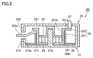
- FIG. 2 is a cross-sectional view taken along the line II-II shown in FIG.
- the low frequency treatment device 100 according to the embodiment will be described with reference to FIGS. 1 and 2.
- the low frequency treatment device 100 includes a main body portion 10, a guide cord 30, and a plurality of electrode pads 40.
- the main body portion 10 includes a circuit portion 15 and a cord reel portion 20.
- the circuit unit 15 and the cord reel unit 20 are housed inside the main body unit 10.
- the circuit unit 15 controls the operation of various electronic components.
- the circuit unit 15 controls the output and waveform of electricity applied to the electrode pads.
- the circuit unit 15 is electrically connected to a contact plate 26, which will be described later, included in the cord reel unit 20 via fixed contacts (not shown), wiring, and the like.
- the cord reel portion 20 is provided so that the conductor cord 30 can be wound up.
- the cord reel portion 20 includes a lower case 21, an upper case 22, a reel portion 23, an elastic urging member 24, a holding plate 25, a contact plate 26, and a brake portion 27.
- the lower case 21 has a bottom portion 211, a side wall portion 212, and a shaft portion 213.
- the bottom portion 211 has a substantially disk shape.
- a shaft portion 213 is provided at the center of the bottom portion 211.
- the shaft portion 213 is provided so as to extend toward the ceiling portion 221 of the upper case 22.
- the side wall portion 212 is provided so as to stand up from the peripheral edge of the bottom portion 211.
- the side wall portion 212 is provided with an outlet 212a for taking out the guide cord 30.
- the upper case 22 includes a ceiling portion 221 and a side wall portion 222.
- the ceiling portion 221 faces the bottom portion 211.
- the side wall portion 222 is provided so as to hang down from the peripheral edge of the ceiling portion 221.
- the side wall portion 222 is arranged outside the side wall portion 212.
- the side wall portion 222 is provided with an outlet 222a for taking out the guide cord 30.
- the outlet 222a communicates with the outlet 212a.
- the reel portion 23 has a tubular portion 231 and a flange portion 232.
- the tubular portion 231 has a bottomed tubular shape.
- the flange portion 232 is provided at the tip of the tubular portion 231 and extends radially outward of the tubular portion 231.
- the tubular portion 231 has an outer peripheral surface 231a and an inner peripheral surface 231b.
- a guide cord 30 is wound around the outer peripheral surface 231a.
- the reel portion 23 is rotatably provided with the shaft portion 213 as a rotation shaft by the elastic urging member 24.
- the elastic urging member 24 is composed of, for example, a spiral spring.
- the elastic urging member 24 exerts an elastic urging force in the direction of winding the conductor cord 30.
- the elastic urging member 24 has one end and the other end.
- One end of the elastic urging member 24 is fixed to the shaft portion 213.
- the other end of the elastic urging member 24 is fixed to the inner peripheral surface 231b.
- the contact plate 26 has a substantially annular shape and is arranged around the bottom of the reel portion 23.
- the contact plate 26 is arranged on the bottom 211 of the lower case 21.
- the contact plate 26 may rotate with the rotation of the reel portion 23.
- the brake portion 27 is provided so as to be able to switch between a state in which winding of the guide cord 30 by the reel portion 23 is stopped and a state in which winding of the guide cord 30 by the reel portion 23 is permitted.
- the brake portion 27 is provided by a switch mechanism (not shown) so as to be able to switch between an abutting state in which the reel portion 23 abuts on the flange portion 232 and a non-contact state in which the reel portion 23 does not abut on the flange portion 232. There is.
- the reel portion 23 can rotate in the winding direction, and the guide cord 30 is wound by the reel portion 23.
- the brake portion 27 In the abutting state, the brake portion 27 generates a frictional force between the brake portion 27 and the reel portion 23 that is larger than the elastic urging force of the elastic urging member 24, and the reel portion 23 rotates in the winding direction. Is stopped.
- the brake portion 27 may be configured so that the guide cord 30 can be pressed against the reel portion 23, the lower case 21, or the upper case 22. In this case, the brake portion 27 presses the guide cord 30 against the reel portion 23, the lower case 21, or the upper case 22, so that the guide cord 30 cannot be wound by the reel portion 23. On the other hand, when the pressing by the reel portion 23 is released, the guide cord 30 can be wound by the reel portion 23.
- the guide cord 30 has one end 30a and the other end 30b.
- One end 30a of the guide cord 30 is provided with a connector portion 35 that is detachably connected to the electrode pad 40.
- a cord reel portion 20 is provided on the other end 30b side of the guide cord 30.
- the conductor cord 30 includes a conductor portion and a covering portion that covers the conductor portion.
- the hardness of the covering portion is a value specified by Type A in accordance with JIS K6253, and may be larger than 0 and 95 or less.
- the fineness of the guide cord 30 may be 3 mm or less in diameter including the covering portion.
- the length of the guide cord 30 may be 1 m or more. The hardness of the covering portion, the fineness of the cord, and the length of the cord are applied to each of the first cord portion 31 and the second cord portion 32, which will be described later.
- the guide cord 30 includes a first cord portion 31 and a second cord portion 32 that are detachably connected to each other.
- the first cord portion 31 includes a first end portion 311 and a second end portion 312.
- the first end portion 311 includes one end 30a of the guide cord 30.
- the first end portion 311 is provided with a connector portion 35.
- the second end portion 312 is located on the opposite side of the first end portion 311.
- the second end portion 312 is provided with a fitting portion 313.
- the fitting portion 313 is provided so as to be able to be fitted to the fitted portion 323 of the second cord portion 32, which will be described later.
- the fitting portion 313 is composed of, for example, a male terminal.
- the fitting portion 313 has a tip portion 313a facing the fitted portion 323 and a terminal portion 313b located on the opposite side of the tip portion 313a.
- the first code unit 31 includes a plurality of branch codes 315 branched according to the number of electrode pads 40. In the present embodiment, two electrode pads 40 are provided, and the first cord portion 31 is branched into two branch cords 315.
- each of the branch cords 315 connected to each of the electrode pads 40 can be moved starting from the branch portion of the first cord portion 31. Therefore, the degree of freedom of the branch code 315 is improved, and the burden on the user due to the guide code 30 can be suppressed during use.
- the number of electrode pads 40 is not limited to two, and may be three or more, and in this case, the branch code 315 may also be three or more. Further, the electrode pad 40 may be singular, and in this case, the first cord portion 31 is not branched.
- the plurality of branch cords 315 are branched at the terminal portion 313b of the fitting portion 313. As a result, the length of the branch code 315 can be increased. As a result, the degree of freedom of the branch code 315 is improved, and the burden on the user due to the guide code 30 during use can be suppressed.
- each of the plurality of branch codes 315 is thinner than the second code portion 32. As a result, the flexibility of the plurality of branch cords 315 can be improved, and the burden on the user due to the guide cord 30 during use can be suppressed.
- the second cord portion 32 has a third end portion 321 and a fourth end portion 322.
- the third end portion 321 includes the other end 30b of the guide cord 30.
- the third end portion 321 is connected to the contact plate 26 of the cord reel portion 20.
- the connection strength between the third end portion 321 and the cord reel portion 20 is, for example, approximately 4.5 kgf or more.
- the fourth end portion 322 is located on the opposite side of the third end portion 321.
- the fourth end portion 322 is provided with a fitted portion 323 that is detachably fitted to the fitting portion 313.
- the fitted portion 323 is configured by, for example, a female terminal.
- the fitting strength for releasing the fitting between the fitting portion 313 and the fitted portion 323 is approximately 2.0 kgf.
- the electrode pad 40 is detachably connected to the connector portion 35.
- the electrode pad 40 includes a conductive gel layer 41, an electrode portion, and a cover portion 42 when used.
- the conductive gel layer 41 has a first surface that comes into contact with the surface of the living body and a second surface that faces the side opposite to the surface of the living body in the state of use.
- the electrode portion is provided on the second surface.
- the electrode portion is provided with a snap portion, and the snap portion is electrically connected to the connector portion 35 described above.
- the cover portion 42 has an insulating property and is provided so as to cover the electrode portion.
- the breaking strength (breaking strength) at which the guide cord 30 is damaged when the one end 30a side of the guide cord 30 is pulled while the fitting portion 313 and the fitted portion 323 are fitted is approximately the same. It is 4 kgf.
- the connector portion 35 is connected to the cord reel portion 20 in a state where the fitting portion 313 and the fitted portion 323 are fitted and the connector portion 35 and the electrode pad 40 are connected.
- a large tensile force acts on the connector portion 35.
- the breaking strength at which the connector portion 35 is broken by such a tensile force is, for example, approximately 4 kgf.
- the breaking strength of the connector portion 35 is different from the strength at which the connection between the connector portion 35 and the electrode pad 40 is released (the strength at which the connector portion 35 is detached from the snap portion of the electrode pad 40). 35 is the strength at which it breaks.
- the cord reel portion 20 is provided, and the conductor cord 30 is wound by the cord reel portion 20, so that the length of the conductor cord becomes longer. Even in such a case, the storability can be improved.
- the guide cord 30 includes a detachably provided first cord portion 31 and a second cord portion 32, so that the portion where the first cord portion 31 and the second cord portion 32 are fitted is used as a starting point. , The first cord portion 31 connected to the electrode pad 40 can be moved. Therefore, as compared with the case where the guide cord 30 is connected from the cord reel portion 20 to the electrode pad 40 without being divided, the degree of freedom of the first cord portion 31 is increased, and the guide cord 30 is used during use.
- the length of the first cord portion 31 can be increased, which also reduces the discomfort that the guide cord 30 touches the skin and maintains a comfortable posture for the user during use. Can be done. As a result, it is possible to suppress the burden on the user due to the guide cord 30 during use.
- the fitting strength is smaller than the connection strength and the breakage strength. Therefore, in order to pull out the guide cord 30 from the cord reel portion 20 in a state where the fitting portion 313 and the fitted portion 323 are fitted, the one end 30a side of the guide cord 30 (first cord portion 31). When the first end portion 311 side of the above) is pulled, the first cord portion 31 is before the connector portion 35 is broken and before the cord reel portion 20 and the conductor cord 30 are separated. And the second cord portion 32 can be released from the fitting. Therefore, it is possible to prevent the connector portion 35 and the connection portion between the cord reel portion 20 and the guide cord 30 from being damaged.
- the connection between the cord reel portion 20 and the second cord portion 32 when the connection between the cord reel portion 20 and the second cord portion 32 is broken, when repairing, the cord reel portion 20 is disassembled and a new second cord portion 32 is reconnected. Is required, and it takes time to repair. Further, when the cord reel portion 20 whose connection is broken is replaced with a new cord reel portion 20 to which another second cord portion 32 is connected, it is costly. As described above, by preferentially releasing the fitting between the first cord portion 31 and the second cord portion 32, the cost and labor for repair can be significantly reduced.
- a cord reel portion (20) provided on the other end (30b) side of the guide cord (30) and provided so that the guide cord (30) can be wound up is provided.
- the guide cord (30) includes a first cord portion (31) and a second cord portion (32) that are detachably connected to each other.
- the first cord portion (31) includes a first end portion (311) including the one end (30a) of the guide cord (30) and provided with the connector portion (35), and the first end portion (311).
- the second cord portion (32) is located on the opposite side of the third end portion (321) including the other end (30b) of the guide cord (30) and the third end portion (321).
- a fourth end portion (322) provided with a fitted portion (323) that is detachably fitted to the fitting portion (313).
- the fitting strength at which the fitting portion (313) and the fitted portion (323) are released from the fitting is the connection strength between the third end portion (321) and the cord reel portion (20).
- the guide cord (30a) A low frequency treatment device (100) that is less than the breaking strength at which 30) breaks.
- the first cord portion (31) includes a plurality of branched cords (315) branched according to the number of electrode pads (40) to be connected.
- the low frequency treatment device (100) according to the configuration 1, wherein the connector portion (35) is provided at the tip of each of the plurality of branch cords (315).
- the fitting portion (313) has a tip portion (313a) facing the fitted portion (323) and a terminal portion (313b) located on the opposite side of the tip portion (313a).
- the low frequency treatment device (100) according to the configuration 2, wherein the first cord portion (31) is branched into a plurality of portions at the terminal portion (313b).
Landscapes
- Health & Medical Sciences (AREA)
- Engineering & Computer Science (AREA)
- Biomedical Technology (AREA)
- Nuclear Medicine, Radiotherapy & Molecular Imaging (AREA)
- Radiology & Medical Imaging (AREA)
- Life Sciences & Earth Sciences (AREA)
- Animal Behavior & Ethology (AREA)
- General Health & Medical Sciences (AREA)
- Public Health (AREA)
- Veterinary Medicine (AREA)
- Electrotherapy Devices (AREA)
Abstract
低周波治療器(100)は、一端(30a)に電極パッド(40)に接続されるコネクタ部(35)を有する導子コード(30)と、導子コード(30)を巻取可能に設けられたコードリール部(20)と、を備え、導子コード(30)は、第1コード部(31)と第2コード部(32)とを含み、第1コード部(31)は、コネクタ部(35)が設けられた第1端部(311)と、嵌合部(313)が設けられた第2端部(312)とを含み、第2コード部(32)は、第3端部と、被嵌合部(323)が設けられた第4端部(322)とを含み、嵌合部(313)と被嵌合部(323)との嵌合が解除される嵌合強度は、第3端部とコードリール部(20)との接続強度、および、導子コード(30)の一端(30a)側を引張した際に導子コード(30)が破損する破損強度よりも小さい。
Description
本開示は、低周波治療器に関する。
従来の低周波治療器として、特開2009-136472号公報(特許文献1)には、導子コードの一端に低周波治療器本体部に接続するためのプラグを設け、当該プラグを低周波治療器本体部に差し込んで使用するタイプのものが開示されている。
低周波治療器においては、電極パッドを治療部位に貼り付けて一定の時間電気を流している。使用者には、楽な体勢での治療や導子コードが肌に触れる不快感の低減など、治療時の負担を低減することが求められている。
特許文献1に開示されている導子コードをより長くした場合には、様々な部位に貼り付けやすくなり、低周波治療器本体部が離れていても、自由な体勢で治療できる。しかしながら、導子コードが長くなることにより、収納が煩雑となったり、導子コードが周囲の物に絡まったりすることが懸念される。
一方、導子コードをより柔らかく細くすることで、導子コードが肌に触れる不快感を低減することができるが、この場合には、導子コード自身の強度、および導子コードのうち電極パッドに接続するための接続部分の根元部の強度が低下してしまう。このため、導子コードが破損し、導通できなくなる懸念される。
上述のような収納性の煩雑さを解消するために、コードリールを設けて、導子コードを巻き取り式に変更することが考えられる。しかしながら、この場合には、導子コードを引き出す際に、コードリール側の端部付近まで導子コードを引き出してしまうことで、導子コードや上記接続部分を破損するリスクが高くなる。また、導子コードが破損した場合には、導子コードが固定されたコードリールごと交換する必要が生じる。この策として、導子コードを太く、かつ、硬くすることが考えられるが、この場合には、部品として導子コードが大きくなるため、その長さにも制限が必要となる。
本開示は、上記のような問題に鑑みてなされたものであり、本開示の目的は、導子コードによる使用者への負担を軽減するとともに、収納性に優れ、破損しにくい低周波治療器を提供することにある。
本開示に基づく低周波治療器は、一端および他端を有し、上記一端に電極パッドに着脱可能に接続されるコネクタ部を有する導子コードと、上記導子コードの上記他端側に設けられ、上記導子コードを巻取可能に設けられたコードリール部と、を備える。上記導子コードは、互いに着脱可能に接続される第1コード部と第2コード部とを含む。上記第1コード部は、上記導子コードの上記一端を含み上記コネクタ部が設けられた第1端部と、上記第1端部とは反対側に位置し、嵌合部が設けられた第2端部とを含む。上記第2コード部は、上記導子コードの上記他端を含み、上記コードリール部に接続された第3端部と、上記第3端部とは反対側に位置し、上記嵌合部に着脱可能に嵌合される被嵌合部が設けられた第4端部とを含む。上記嵌合部と上記被嵌合部との嵌合が解除される嵌合強度は、上記第3端部と上記コードリール部との接続強度、および、上記嵌合部と上記被嵌合部とが嵌合された状態で、上記導子コードの上記一端側を引張した際に上記導子コードが破損する破損強度よりも小さい。
上記構成によれば、低周波治療器を使用しない状態においては、コードリールによって導子コードを巻き取ることにより、導子コードの長さが長くなった場合であっても、収納性を向上させることができる。さらに、導子コードが、着脱可能に設けられた第1コード部と第2コード部を含むことにより、第1コード部と第2コード部とが嵌合する部分を起点として、電極パッドに接続される第1コード部を移動させることができる。このため、導子コードがコードリール部から電極パッドまで分割されずに接続される場合と比較して、第1コード部の自由度が増し、使用中における導子コードによる使用者への不快感等の負担を抑制することができる。また、第1コード部の長さを長くすることができ、このことによっても、導子コードが肌に触れる不快感等を低減できたり、使用中に使用者が楽な姿勢を維持したりすることができる。この結果、使用中における導子コードによる使用者への負担を抑制することができる。
加えて、第1コード部の嵌合部と第2コード部の被嵌合部とを解除するための嵌合強度を、第2コード部とコードリール部との接続強度、および、上記嵌合部と上記被嵌合部とが嵌合された状態で上記導子コードの上記一端側(第1コード部の第1端部側)を引張した際に導子コードが破損する破損強度よりも小さくすることにより、使用者が、導子コードを引っ張った場合に、導子コードが破損するより先に、かつ、コードリール部と導子コードとが分離されるよりも先に、第1コード部と第2コード部との嵌合を解除することができる。このため、導子コード、およびコードリール部と導子コードとの接続部が破損することを抑制することができる。
さらには、コードリール部と第2コード部との接続が破断された場合には、修理する場合には、コードリール部を分解し、新たな第2コード部を接続し直すことが必要となり、修理に手間がかかる。また、接続が破断されたコードリール部を、別の第2コード部が接続された新たなコードリール部に交換する場合には、コストがかかってしまう。上記のように、第1コード部と第2コード部との嵌合を優先的に解除させることにより、修理のためのコストおよび手間を大幅に削減することができる。
上記本開示に基づく低周波治療器にあっては、上記第1コード部は、接続される電極パッドの個数に応じて分岐された複数の分岐コードを含んでいてもよく、上記複数の分岐コードの各々が有する先端に上記コネクタ部が設けられていてもよい。
上記構成によれば、複数の分岐コードの各々に電極パッドを接続することで、複数の部位を治療できるようになり、利便性を向上させることができる。また、複数の分岐コードは、それぞれ、第1コード部の分岐部を起点として移動させることができるため、分岐コードの自由度が向上し、使用中における導子コードによる使用者への負担を抑制することができる。
上記本開示に基づく低周波治療器にあっては、上記嵌合部は、上記被嵌合部に対向する先端部と、当該先端部とは反対側に位置する末端部とを有していてもよい。この場合には、上記複数の分岐コードは、上記末端部で複数に分岐していてもよい。
上記構成によれば、嵌合部の末端部側で複数の分岐コードを分岐させることにより、分岐コードの長さを長くすることができる。これにより、分岐コードの自由度が向上し、使用中における導子コードによる使用者への負担を抑制することができる。
上記本開示に基づく低周波治療器にあっては、上記複数の分岐コードの各々は、上記第2コード部よりも細くてもよい。
上記構成によれば、複数の分岐コードの柔軟性を向上させることができ、使用中における導子コードによる使用者への負担を抑制することができる。
本開示によれば、導子コードによる使用者への負担を軽減するとともに、収納性に優れ、破損しにくい低周波治療器を提供することができる。
以下、本開示の実施の形態について、図を参照して詳細に説明する。なお、以下に示す実施の形態においては、同一のまたは共通する部分について図中同一の符号を付し、その説明は繰り返さない。
図1は、実施の形態に係る低周波治療器の概略図である。図2は、図1に示すII-II線に沿った断面図である。図1および図2を参照して、実施の形態に係る低周波治療器100について説明する。
図1および図2に示すように、実施の形態に係る低周波治療器100は、本体部10、導子コード30、および複数の電極パッド40を備える。
本体部10は、回路部15、およびコードリール部20を含む。回路部15およびコードリール部20は、本体部10の内部に収容されている。
回路部15は、各種電子部品の動作を制御する。回路部15は、電極パッドに与える電気の出力および波形を制御する。回路部15は、不図示の固定接点、および配線等を介して、コードリール部20に含まれる後述の接点板26に電気的に接続されている。
コードリール部20は、導子コード30を巻き取り可能に設けられている。コードリール部20は、下部ケース21、上部ケース22、リール部23、弾性付勢部材24、押さえ板25、接点板26、およびブレーキ部27を含む。
下部ケース21は、底部211、側壁部212、および軸部213を有する。底部211は、略円板形状を有する。底部211の中心部には、軸部213が設けられている。軸部213は、上部ケース22の天井部221に向けて延びるように設けられている。側壁部212は、底部211の周縁から起立するように設けられている。側壁部212には、導子コード30を取り出すための取出口212aが設けられている。
上部ケース22は、天井部221、側壁部222を含む。天井部221は、底部211に対向する。側壁部222は、天井部221の周縁から垂下するように設けられている。側壁部222は、上記側壁部212の外側に配置される。側壁部222には、導子コード30を取り出すための取出口222aが設けられている。当該取出口222aは、上記取出口212aに連通する。
リール部23は、筒状部231および鍔部232を有する。筒状部231は、有底筒状形状を有する。鍔部232は、筒状部231の先端に設けられ、筒状部231の径方向外側に向けて延在する。
筒状部231は、外周面231aおよび内周面231bを有する。外周面231aには、導子コード30が巻き付けられている。
リール部23は、弾性付勢部材24によって、軸部213を回転軸として回転可能に設けられている。
弾性付勢部材24は、たとえば渦巻き状のぜんまいばねによって構成されている。弾性付勢部材24は、導子コード30を巻き取る方向に弾性付勢力を発現させる。弾性付勢部材24は、一端および他端を有する。弾性付勢部材24の一端は、上記軸部213に固定されている。弾性付勢部材24の他端は、上記内周面231bに固定されている。
接点板26は、略環状形状を有し、リール部23の底部の周囲に配置されている。接点板26は、下部ケース21の底部211上に配置されている。接点板26は、リール部23の回転に伴って回転してもよい。
ブレーキ部27は、リール部23による導子コード30の巻き取りを停止する状態と、リール部23による導子コード30の巻き取りを許容する状態とを切り替え可能に設けられている。
ブレーキ部27は、不図示のスイッチ機構によって、リール部23の鍔部232に当接する当接状態と、リール部23の鍔部232に当接しない非当接状態とを切り替え可能に設けられている。
非当接状態においては、巻き取り方向へのリール部23の回転が可能となり、リール部23によって導子コード30が巻き取られる。
当接状態においては、ブレーキ部27によって、ブレーキ部27とリール部23との間に弾性付勢部材24による弾性付勢力よりも大きい摩擦力が発生し、巻き取り方向へのリール部23の回転が停止される。
なお、上述においては、ブレーキ部27は、リール部23に当接するように構成されている場合を例示して説明したが、これに限定されない。ブレーキ部27は、リール部23、下部ケース21、または上部ケース22に導子コード30を押し付け可能に構成されていてもよい。この場合には、ブレーキ部27が、リール部23、下部ケース21、または上部ケース22に導子コード30を押し付けることで、リール部23による導子コード30の巻き取りが不能となる。一方、リール部23による押し付けが解除されると、リール部23による導子コード30の巻き取りが可能となる。
導子コード30は、一端30aおよび他端30bを有する。導子コード30の一端30aには、電極パッド40に着脱可能に接続されるコネクタ部35が設けられている。導子コード30の他端30b側には、コードリール部20が設けられている。
導子コード30は、導線部と、当該導線部を被覆する被覆部とを含む。被覆部の硬さは、JIS K 6253に準拠したタイプAで規格される値であり、0より大きく95以下であってもよい。導子コード30の細さは、被覆部を含めて直径3mm以下であってもよい。導子コード30の長さは、1m以上であってもよい。なお、これら被覆部の硬さ、コードの細さ、およびコードの長さは、後述する第1コード部31および第2コード部32の各々に適用される。
導子コード30は、互いに着脱可能に接続される第1コード部31および第2コード部32を含む。
第1コード部31は、第1端部311および第2端部312を含む。第1端部311は、導子コード30の一端30aを含む。第1端部311には、コネクタ部35が設けられている。第2端部312は、第1端部311とは反対側に位置する。第2端部312には、嵌合部313が設けられている。
嵌合部313は、後述する第2コード部32の被嵌合部323に嵌合可能に設けられている。嵌合部313は、たとえば、オス端子によって構成されている。嵌合部313は、被嵌合部323に対向する先端部313a、および当該先端部313aとは反対側に位置する末端部313bを有する。
第1コード部31は、電極パッド40の個数に応じて分岐された複数の分岐コード315を含む。本実施の形態においては、電極パッド40は、2つ設けられており、第1コード部31は、2本の分岐コード315に分岐している。
このように複数の分岐コード31の各々に電極パッド40を接続する場合には、複数の部位を治療できるようになり、利便性を向上させることができる。また、各々の電極パッド40に接続された分岐コード315は、それぞれ、第1コード部31の分岐部を起点として移動させることができる。このため、分岐コード315の自由度が向上し、使用中において導子コード30による使用者への負担を抑制することができる。
なお、電極パッド40の個数は、2つに限定されず、3つ以上であってもよく、この場合には、分岐コード315も3本以上であってもよい。また、電極パッド40は、単数でもよく、この場合には、第1コード部31は分岐されない。
複数の分岐コード315は、嵌合部313の末端部313bで分岐している。これにより、分岐コード315の長さを長くすることができる。この結果、分岐コード315の自由度が向上し、使用中における導子コード30による使用者への負担を抑制することができる。
さらに、複数の分岐コード315の各々は、第2コード部32よりも細くなっている。これにより、複数の分岐コード315の柔軟性を向上させることができ、使用中における導子コード30による使用者への負担を抑制することができる。
第2コード部32は、第3端部321および第4端部322を有する。第3端部321は、導子コード30の他端30bを含む。第3端部321は、コードリール部20の接点板26に接続されている。第3端部321とコードリール部20との接続強度は、たとえば、略4.5kgf以上である。
第4端部322は、第3端部321とは反対側に位置する。第4端部322には、上記嵌合部313に着脱可能に嵌合される被嵌合部323が設けられている。被嵌合部323は、たとえば、メス端子によって構成されている。嵌合部313と被嵌合部323との嵌合を解除するための嵌合強度は、略2.0kgfである。
電極パッド40は、上記コネクタ部35に着脱可能に接続される。電極パッド40は、使用時に、導電性ゲル層41、電極部、およびカバー部42を含む。導電性ゲル層41は、使用状態において、生体表面に接触する第1面と、生体表面とは反対側を向く第2面とを有する。電極部は、第2面に設けられている。電極部にはスナップ部が設けられており、当該スナップ部によって上述のコネクタ部35と電気的に接続される。カバー部42は、絶縁性を有し、上記電極部を覆うように設けられている。
上記嵌合部313および上記被嵌合部323が嵌合された状態で、導子コード30の一端30a側を引張した際に上記導子コード30が破損する破損強度(破断強度)は、略4kgfである。
具体的には、嵌合部313および被嵌合部323が嵌合され、かつ、コネクタ部35および電極パッド40が接続された状態で、導子コード30をコードリール部20から引き出すために、電極パッド40ごと導子コード30の一端30a側を引張した場合に、コネクタ部35に引張力が大きく作用する。このような引張力によってコネクタ部35が破断する破断強度は、たとえば、略4kgfである。なお、コネクタ部35の破断強度とは、コネクタ部35と電極パッド40との接続が解除される強度(電極パッド40のスナップ部からコネクタ部35が外れる強度)とは異なるものであり、コネクタ部35が破断する強度である。
以上のように、実施の形態に係る低周波治療器100においては、コードリール部20を設け、当該コードリール部20によって導子コード30を巻き取ることにより、導子コードの長さが長くなった場合であっても、収納性を向上させることができる。さらに、導子コード30が、着脱可能に設けられた第1コード部31と第2コード部32を含むことにより、第1コード部31と第2コード部32とが嵌合する部分を起点として、電極パッド40に接続される第1コード部31を移動させることができる。このため、導子コード30がコードリール部20から電極パッド40まで分割されずに接続される場合と比較して、第1コード部31の自由度が増し、使用中における導子コード30による使用者への不快感等の負担を抑制することができる。また、第1コード部31の長さを長くすることができ、このことによっても、導子コード30が肌に触れる不快感等を低減できたり、使用中に使用者が楽な姿勢を維持したりすることができる。この結果、使用中における導子コード30による使用者への負担を抑制することができる。
加えて、上記嵌合強度が、上記接続強度、および上記破損強度よりも小さくなっている。このため、嵌合部313および被嵌合部323が嵌合された状態で、導子コード30をコードリール部20から引き出すために、導子コード30の上記一端30a側(第1コード部31の第1端部311側)を引張した場合に、コネクタ部35が破断するより先に、かつ、コードリール部20と導子コード30とが分離されるよりも先に、第1コード部31と第2コード部32との嵌合を解除することができる。このため、コネクタ部35、およびコードリール部20と導子コード30との接続部が破損することを抑制することができる。
さらには、コードリール部20と第2コード部32との接続が破断された場合には、修理する場合には、コードリール部20を分解し、新たな第2コード部32を接続し直すことが必要となり、修理に手間がかかる。また、接続が破断されたコードリール部20を、別の第2コード部32が接続された新たなコードリール部20に交換する場合には、コストがかかってしまう。上記のように、第1コード部31と第2コード部32との嵌合を優先的に解除させることにより、修理のためのコストおよび手間を大幅に削減することができる。
[付記]
以上のように、本実施形態は以下のような開示を含む。
以上のように、本実施形態は以下のような開示を含む。
[構成1]
一端(30a)および他端(30b)を有し、上記一端(30a)に電極パッド(40)に着脱可能に接続されるコネクタ部(35)を有する導子コード(30)と、
上記導子コード(30)の上記他端(30b)側に設けられ、上記導子コード(30)を巻取可能に設けられたコードリール部(20)と、を備え、
上記導子コード(30)は、互いに着脱可能に接続される第1コード部(31)と第2コード部(32)とを含み、
上記第1コード部(31)は、上記導子コード(30)の上記一端(30a)を含み上記コネクタ部(35)が設けられた第1端部(311)と、上記第1端部(311)とは反対側に位置し、嵌合部(313)が設けられた第2端部(312)とを含み、
上記第2コード部(32)は、上記導子コード(30)の上記他端(30b)を含む第3端部(321)と、上記第3端部(321)とは反対側に位置し、上記嵌合部(313)に着脱可能に嵌合される被嵌合部(323)が設けられた第4端部(322)とを含み、
上記嵌合部(313)と上記被嵌合部(323)との嵌合が解除される嵌合強度は、上記第3端部(321)と上記コードリール部(20)との接続強度、および、上記嵌合部(313)および上記被嵌合部(323)が嵌合された状態で、上記導子コード(30)の上記一端(30a)側を引張した際に上記導子コード(30)が破損する破損強度よりも小さい、低周波治療器(100)。
一端(30a)および他端(30b)を有し、上記一端(30a)に電極パッド(40)に着脱可能に接続されるコネクタ部(35)を有する導子コード(30)と、
上記導子コード(30)の上記他端(30b)側に設けられ、上記導子コード(30)を巻取可能に設けられたコードリール部(20)と、を備え、
上記導子コード(30)は、互いに着脱可能に接続される第1コード部(31)と第2コード部(32)とを含み、
上記第1コード部(31)は、上記導子コード(30)の上記一端(30a)を含み上記コネクタ部(35)が設けられた第1端部(311)と、上記第1端部(311)とは反対側に位置し、嵌合部(313)が設けられた第2端部(312)とを含み、
上記第2コード部(32)は、上記導子コード(30)の上記他端(30b)を含む第3端部(321)と、上記第3端部(321)とは反対側に位置し、上記嵌合部(313)に着脱可能に嵌合される被嵌合部(323)が設けられた第4端部(322)とを含み、
上記嵌合部(313)と上記被嵌合部(323)との嵌合が解除される嵌合強度は、上記第3端部(321)と上記コードリール部(20)との接続強度、および、上記嵌合部(313)および上記被嵌合部(323)が嵌合された状態で、上記導子コード(30)の上記一端(30a)側を引張した際に上記導子コード(30)が破損する破損強度よりも小さい、低周波治療器(100)。
[構成2]
上記第1コード部(31)は、接続される電極パッド(40)の個数に応じて分岐された複数の分岐コード(315)を含み、
上記複数の分岐コード(315)の各々が有する先端に上記コネクタ部(35)が設けられている、構成1に記載の低周波治療器(100)。
上記第1コード部(31)は、接続される電極パッド(40)の個数に応じて分岐された複数の分岐コード(315)を含み、
上記複数の分岐コード(315)の各々が有する先端に上記コネクタ部(35)が設けられている、構成1に記載の低周波治療器(100)。
[構成3]
上記嵌合部(313)は、上記被嵌合部(323)に対向する先端部(313a)と、当該先端部(313a)とは反対側に位置する末端部(313b)を有し、
上記第1コード部(31)は、上記末端部(313b)で複数に分岐している、構成2に記載の低周波治療器(100)。
上記嵌合部(313)は、上記被嵌合部(323)に対向する先端部(313a)と、当該先端部(313a)とは反対側に位置する末端部(313b)を有し、
上記第1コード部(31)は、上記末端部(313b)で複数に分岐している、構成2に記載の低周波治療器(100)。
[構成4]
上記複数の分岐コード(315)の各々は、上記第2コード部(32)よりも細い、構成2または3に記載の低周波治療器(100)。
上記複数の分岐コード(315)の各々は、上記第2コード部(32)よりも細い、構成2または3に記載の低周波治療器(100)。
以上、今回開示された実施の形態はすべての点で例示であって制限的なものではない。本発明の範囲は請求の範囲によって示され、請求の範囲と均等の意味および範囲内でのすべての変更が含まれる。
10 本体部、15 回路部、20 コードリール部、21 下部ケース、22 上部ケース、23 リール部、24 弾性付勢部材、25 押さえ板、26 接点板、27 ブレーキ部、30 導子コード、30a 一端、30b 他端、31 第1コード部、32 第2コード部、35 コネクタ部、40 電極パッド、41 導電性ゲル層、42 カバー部、100 低周波治療器、211 底部、212 側壁部、212a 取出口、213 軸部、221 天井部、222 側壁部、222a 取出口、231 筒状部、231a 外周面、231b 内周面、232 鍔部、311 第1端部、312 第2端部、313 嵌合部、313a 先端部、313b 末端部、315 分岐コード、321 第3端部、322 第4端部、323 被嵌合部。
Claims (4)
- 一端および他端を有し、前記一端に電極パッドに着脱可能に接続されるコネクタ部を有する導子コードと、
前記導子コードの前記他端側に設けられ、前記導子コードを巻取可能に設けられたコードリール部と、を備え、
前記導子コードは、互いに着脱可能に接続される第1コード部と第2コード部とを含み、
前記第1コード部は、前記導子コードの前記一端を含み、前記コネクタ部が設けられた第1端部と、前記第1端部とは反対側に位置し、嵌合部が設けられた第2端部とを含み、
前記第2コード部は、前記導子コードの前記他端を含み、前記コードリール部に接続された第3端部と、前記第3端部とは反対側に位置し、前記嵌合部に着脱可能に嵌合される被嵌合部が設けられた第4端部とを含み、
前記嵌合部と前記被嵌合部との嵌合が解除される嵌合強度は、前記第3端部と前記コードリール部との接続強度、および、前記嵌合部と前記被嵌合部とが嵌合された状態で、前記導子コードの前記一端側を引張した際に前記導子コードが破損する破損強度よりも小さい、低周波治療器。 - 前記第1コード部は、接続される電極パッドの個数に応じて分岐された複数の分岐コードを含み、
前記複数の分岐コードの各々が有する先端に前記コネクタ部が設けられている、請求項1に記載の低周波治療器。 - 前記嵌合部は、前記被嵌合部に対向する先端部と、当該先端部とは反対側に位置する末端部を有し、
前記複数の分岐コードは、前記末端部で分岐している、請求項2に記載の低周波治療器。 - 前記複数の分岐コードの各々は、前記第2コード部よりも細い、請求項2または3に記載の低周波治療器。
Applications Claiming Priority (2)
| Application Number | Priority Date | Filing Date | Title |
|---|---|---|---|
| JP2020202548A JP2022090268A (ja) | 2020-12-07 | 2020-12-07 | 低周波治療器 |
| JP2020-202548 | 2020-12-07 |
Publications (1)
| Publication Number | Publication Date |
|---|---|
| WO2022124227A1 true WO2022124227A1 (ja) | 2022-06-16 |
Family
ID=81973245
Family Applications (1)
| Application Number | Title | Priority Date | Filing Date |
|---|---|---|---|
| PCT/JP2021/044449 Ceased WO2022124227A1 (ja) | 2020-12-07 | 2021-12-03 | 低周波治療器 |
Country Status (2)
| Country | Link |
|---|---|
| JP (1) | JP2022090268A (ja) |
| WO (1) | WO2022124227A1 (ja) |
Families Citing this family (1)
| Publication number | Priority date | Publication date | Assignee | Title |
|---|---|---|---|---|
| KR102666947B1 (ko) * | 2023-09-22 | 2024-05-20 | (주)영인바이오텍 | 고주파 및 저주파 자극 기능을 가지는 온열 자극기 |
Citations (4)
| Publication number | Priority date | Publication date | Assignee | Title |
|---|---|---|---|---|
| JPS57130651U (ja) * | 1981-02-09 | 1982-08-14 | ||
| JPH04128507U (ja) * | 1991-05-17 | 1992-11-24 | テイアツク株式会社 | モータ取付構造 |
| US20140107718A1 (en) * | 2012-10-11 | 2014-04-17 | Heartlife Technology, Llc | Automated external defibrillator attachment for electronic device |
| US20160250466A1 (en) * | 2014-11-26 | 2016-09-01 | Ndi Medical, Llc | Electrical stimulator for peripheral stimulation |
-
2020
- 2020-12-07 JP JP2020202548A patent/JP2022090268A/ja active Pending
-
2021
- 2021-12-03 WO PCT/JP2021/044449 patent/WO2022124227A1/ja not_active Ceased
Patent Citations (4)
| Publication number | Priority date | Publication date | Assignee | Title |
|---|---|---|---|---|
| JPS57130651U (ja) * | 1981-02-09 | 1982-08-14 | ||
| JPH04128507U (ja) * | 1991-05-17 | 1992-11-24 | テイアツク株式会社 | モータ取付構造 |
| US20140107718A1 (en) * | 2012-10-11 | 2014-04-17 | Heartlife Technology, Llc | Automated external defibrillator attachment for electronic device |
| US20160250466A1 (en) * | 2014-11-26 | 2016-09-01 | Ndi Medical, Llc | Electrical stimulator for peripheral stimulation |
Also Published As
| Publication number | Publication date |
|---|---|
| JP2022090268A (ja) | 2022-06-17 |
Similar Documents
| Publication | Publication Date | Title |
|---|---|---|
| CN101442693B (zh) | 耳机线收线装置、自动收线耳机、无辐射有线手机及电子设备 | |
| ES2762190T3 (es) | Conector de electrodo ECG | |
| CN102160786A (zh) | 扣式电极与导联线的连接结构 | |
| US8787743B2 (en) | Cable connection structure and endoscope apparatus | |
| CA2800131A1 (en) | An improved percutaneous lead | |
| CN101495176A (zh) | 低频治疗仪用传输电线以及安装有该传输电线的电极敷垫 | |
| JPWO2016166828A1 (ja) | 屈曲処置具用操作部 | |
| JP2022090268A (ja) | 低周波治療器 | |
| JP5484202B2 (ja) | フック | |
| US20200267466A1 (en) | Earphones With Removable Connection Cable | |
| KR102667458B1 (ko) | 근력 보조 장치 | |
| CN102961823B (zh) | 低频治疗仪 | |
| JP2009176615A (ja) | コード用ブッシング、コード用コネクタ、ブッシング付コード、およびコード付装置 | |
| WO2013094627A1 (ja) | 信号ケーブル及び電子機器並びに信号ケーブルの製造方法 | |
| CN114156682A (zh) | 抗电磁波干扰的多功能数据线 | |
| CN224166582U (zh) | 一种可用于辅助医疗的按摩装置 | |
| KR101281531B1 (ko) | 의료용 레이저 전달장치 | |
| CN208753575U (zh) | 一种输电电缆 | |
| JP2024101961A (ja) | 電位治療器 | |
| JP7087622B2 (ja) | 電気治療器、および治療システム | |
| JP2023097670A (ja) | 動作制御装置及び物理療法用装置 | |
| CN218828165U (zh) | 一种接口座及电子设备 | |
| CN218389892U (zh) | 腰带 | |
| CN221648093U (zh) | 一种可调节屏幕支架和医疗设备 | |
| CN223898779U (zh) | 电线连接组件及具有该组件的手持式器具 |
Legal Events
| Date | Code | Title | Description |
|---|---|---|---|
| 121 | Ep: the epo has been informed by wipo that ep was designated in this application |
Ref document number: 21903330 Country of ref document: EP Kind code of ref document: A1 |
|
| NENP | Non-entry into the national phase |
Ref country code: DE |
|
| 122 | Ep: pct application non-entry in european phase |
Ref document number: 21903330 Country of ref document: EP Kind code of ref document: A1 |