WO2022124016A1 - 密度勾配液作製装置、密度勾配液作製方法、粒子径分布測定システム及び粒子径分布測定方法 - Google Patents
密度勾配液作製装置、密度勾配液作製方法、粒子径分布測定システム及び粒子径分布測定方法 Download PDFInfo
- Publication number
- WO2022124016A1 WO2022124016A1 PCT/JP2021/041914 JP2021041914W WO2022124016A1 WO 2022124016 A1 WO2022124016 A1 WO 2022124016A1 JP 2021041914 W JP2021041914 W JP 2021041914W WO 2022124016 A1 WO2022124016 A1 WO 2022124016A1
- Authority
- WO
- WIPO (PCT)
- Prior art keywords
- solution
- density gradient
- density
- gradient liquid
- unit
- Prior art date
- Legal status (The legal status is an assumption and is not a legal conclusion. Google has not performed a legal analysis and makes no representation as to the accuracy of the status listed.)
- Ceased
Links
Images


Classifications
-
- G—PHYSICS
- G01—MEASURING; TESTING
- G01N—INVESTIGATING OR ANALYSING MATERIALS BY DETERMINING THEIR CHEMICAL OR PHYSICAL PROPERTIES
- G01N15/00—Investigating characteristics of particles; Investigating permeability, pore-volume or surface-area of porous materials
- G01N15/02—Investigating particle size or size distribution
- G01N15/0255—Investigating particle size or size distribution with mechanical, e.g. inertial, classification, and investigation of sorted collections
-
- G—PHYSICS
- G01—MEASURING; TESTING
- G01N—INVESTIGATING OR ANALYSING MATERIALS BY DETERMINING THEIR CHEMICAL OR PHYSICAL PROPERTIES
- G01N15/00—Investigating characteristics of particles; Investigating permeability, pore-volume or surface-area of porous materials
- G01N15/02—Investigating particle size or size distribution
-
- B—PERFORMING OPERATIONS; TRANSPORTING
- B01—PHYSICAL OR CHEMICAL PROCESSES OR APPARATUS IN GENERAL
- B01F—MIXING, e.g. DISSOLVING, EMULSIFYING OR DISPERSING
- B01F35/00—Accessories for mixers; Auxiliary operations or auxiliary devices; Parts or details of general application
- B01F35/80—Forming a predetermined ratio of the substances to be mixed
- B01F35/83—Forming a predetermined ratio of the substances to be mixed by controlling the ratio of two or more flows, e.g. using flow sensing or flow controlling devices
-
- G—PHYSICS
- G01—MEASURING; TESTING
- G01N—INVESTIGATING OR ANALYSING MATERIALS BY DETERMINING THEIR CHEMICAL OR PHYSICAL PROPERTIES
- G01N15/00—Investigating characteristics of particles; Investigating permeability, pore-volume or surface-area of porous materials
- G01N15/04—Investigating sedimentation of particle suspensions
- G01N15/042—Investigating sedimentation of particle suspensions by centrifuging and investigating centrifugates
Definitions
- the present invention relates to a density gradient liquid preparation device and a density gradient liquid preparation method for producing a density gradient liquid in a measurement cell for a centrifugal sedimentation type particle size distribution measurement device, and a particle size distribution measurement system and a particle diameter using the same. It relates to a distribution measurement method.
- a measurement sample is driven into the density gradient liquid of sucrose prepared in the measurement cell, and the measurement sample is rotated to apply centrifugal force to the measurement sample.
- Each of the contained particles is separated into each particle size in the measurement cell.
- the density gradient liquid is produced in the measurement cell using a density gradient liquid preparation device.
- a density gradient liquid preparation device for example, two sucrose solutions having different densities are mixed at different ratios to prepare sucrose solutions having various densities, and the sucrose solutions are gradually increased in density. It is known that a density gradient liquid is produced by supplying it to a measurement cell (for example, Patent Document 1).
- the density gradient liquid used in the line start method is used for each sample type and particle size so that the particles contained in the injected sample do not aggregate in the liquid and the pH is kept as far as possible from the isoelectric point. It needs to be adjusted and manufactured.
- a density gradient solution having a target pH hereinafter, also referred to as a target pH
- a plurality of sucrose solutions having a target pH are manually prepared using a pH adjusting agent such as an acidic solution or an alkaline solution. It is prepared and set in a density gradient liquid preparation device to prepare a density gradient liquid having a target pH.
- the present invention has been made in view of such a problem, and its main object is to provide a density gradient liquid preparation apparatus capable of efficiently producing a plurality of density gradient liquids having different concentrations of aggregation-suppressing components. ..
- the density gradient solution preparation device prepares a density gradient solution in a measurement cell for a centrifugal sedimentation type particle size distribution measuring device, and is a concentration of an aggregation suppressing component that suppresses aggregation of particles.
- a first solution preparation unit that mixes a plurality of first reference solutions different from each other to prepare a first solution having a predetermined target concentration and a first density, and a plurality of second solutions having different concentrations of the aggregation inhibitory components. Mixing the reference solution and mixing the first solution and the second solution with the second solution preparation unit that prepares the second solution having the target concentration and the second density different from the first density. It is characterized by including a mixed solution preparing unit for generating a mixed solution having the target concentration and supplying the mixed solution into the measurement cell by changing the density thereof.
- a first solution and a second solution having a target concentration are prepared by mixing a plurality of reference solutions having different concentrations of aggregation-suppressing components, and a density gradient solution having a target concentration is used.
- a density gradient solution having a target concentration is used.
- the aggregation-suppressing component is specifically a hydrogen ion (H + ), a surfactant, or the like, which is a component that determines the pH of the solution.
- the first solution preparation unit prepares the first solution by mixing a plurality of the first reference solutions having the same density
- the second solution preparation unit prepares the first solution having the same density. It is preferable that the second solution is prepared by mixing the two reference solutions. By doing so, it is not necessary to adjust the mixing ratio of each reference solution so that the first solution and the second solution have the target densities, respectively, so that the first solution and the second solution can be prepared more easily. Can be done.
- the aggregation inhibitory component is hydrogen ion (H + ), and the first solution preparation unit mixes the acidic first reference solution and the alkaline first reference solution.
- the first solution is prepared, and the second solution preparation unit prepares the second solution by mixing the acidic second reference solution and the alkaline second reference solution. Is preferable. In this way, a density gradient liquid having any pH value of acidic, neutral or alkaline can be prepared.
- the first solution preparation unit and the second solution preparation unit each send a plurality of the reference solutions from a plurality of primary pumps and each of the primary pumps.
- a primary mixing unit for mixing the fed liquid reference solution is provided, and the solution having a desired aggregation inhibitory component concentration is prepared by changing the ratio of the liquid feed amount of each of the primary pumps.
- a target concentration acquisition unit for acquiring the target concentration value from the user, the first solution preparation unit and the second solution unit according to the acquired target concentration value.
- Examples thereof include a primary pump control unit that controls the rotation speed of each of the primary pumps, which is provided in each of the solution preparation units.
- the mixed solution preparation unit is fed from two secondary pumps that feed the first solution and the second solution, respectively, and each of the secondary pumps.
- a secondary mixing section for mixing the first solution and the second solution is provided, and the density of the mixed solution produced is changed by changing the ratio of the liquid feed amount of each of the secondary pumps. Things can be mentioned.
- the cell capacity acquisition unit for acquiring the capacity of the measurement cell from the user and the acquired capacity of the measurement cell are described. It is preferable to further include a secondary pump control unit that controls the rotation speed of each secondary pump.
- both the primary pump and the secondary pump are micropumps.
- the method for preparing a density gradient solution of the present invention is a method for preparing a density gradient solution in a measurement cell for a centrifugal sedimentation type particle size distribution measuring device, and the concentrations of aggregation inhibitory components that suppress the aggregation of particles are mutual.
- the particle size distribution measurement system of the present invention is a centrifuge that measures the particle size distribution by the line start method using the above-mentioned density gradient liquid preparation device of the present invention and the density gradient liquid produced by the density gradient liquid preparation device. It is characterized by being provided with a sedimentation type particle size distribution measuring device.
- the density gradient liquid produced by the density gradient liquid producing method of the present invention described above and the centrifugal sedimentation type particle size distribution measuring device are used, and the particle size distribution is distributed by the line start method. It is characterized by making measurements.
- a density gradient liquid producing apparatus capable of efficiently producing a plurality of density gradient liquids having different concentrations of aggregation suppressing components.
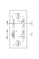
- the figure which shows typically the structure of the density gradient liquid preparation apparatus of this embodiment The functional block diagram of the density gradient liquid preparation apparatus of the same embodiment.
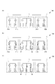
- the figure explaining the operation of the density gradient liquid preparation apparatus of the same embodiment The figure which shows typically the structure of the density gradient liquid preparation apparatus of another embodiment.
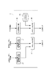
- the functional block diagram of the density gradient liquid preparation apparatus of another embodiment The figure which shows typically the structure of the density gradient liquid preparation apparatus of another embodiment.
- the density gradient liquid preparation apparatus 100 according to the present invention will be described below with reference to the drawings.
- the density gradient liquid preparation device 100 of the present embodiment is used together with the centrifugal sedimentation type particle size distribution measuring device 200, and constitutes the particle size distribution measuring system 300.
- the density gradient liquid preparation device 100 prepares a density gradient liquid composed of a sucrose solution in a measurement cell C (for example, a rectangular cuvette cell having a square cross section) used in the particle size distribution measuring device 200.
- the particle size distribution measuring device 200 measures the particle size distribution of the measurement sample by the line start method using the prepared density gradient liquid.
- this density gradient liquid preparation apparatus 100 accepts a target value (hereinafter, also referred to as a target hydrogen ion concentration) of hydrogen ion (H + ) concentration according to a measurement sample from a user, and a plurality of hydrogen ion concentrations and densities are different.
- a target value hereinafter, also referred to as a target hydrogen ion concentration
- H + hydrogen ion
- the density gradient liquid preparation device 100 mixes a plurality of sucrose solutions to prepare a first sucrose solution 31 having a target hydrogen ion concentration and a first density.
- a mixed sucrose solution having a target hydrogen ion concentration is generated, and the density thereof is changed and supplied into the measurement cell C.
- It includes a solution preparation unit 3 and a control unit 4 that controls each solution preparation unit.
- the first solution preparation unit 1 first mixes a plurality of (here, two) sucrose solutions 11a and 11b (hereinafter, also referred to as a first reference sucrose solution) having known hydrogen ion concentrations and densities.
- a sucrose solution 31 is prepared and supplied to the mixed solution preparation unit 3.
- the first solution preparing unit 1 includes two types of first reference sucrose solutions 11a and 11b having different hydrogen ion concentrations and both densities of the first density, and each first reference sucrose solution 11a.
- the two primary pumps 12a and 12b for feeding 11b and the first reference sucrose solutions 11a and 11b fed from the primary pumps 12a and 12b are mixed and supplied to the mixed solution preparation unit 3. It is provided with a mixing unit 13.
- the two types of first reference sucrose solutions 11a and 11b are an acidic solution having a pH of less than 7 and an alkaline solution having a pH of more than 7.
- the first solution preparation unit 1 prepares the first sucrose solution 31 having a desired pH by changing the ratio of the liquid feed amounts of the primary pumps 12a and 12b based on the control signal received from the control unit 4. It is configured in.
- Each of the primary pumps 12a and 12b sucks out the first reference sucrose solutions 11a and 11b contained in the container through a tube and sends the liquid to the primary mixing unit 13.
- the primary pumps 12a and 12b are capable of continuously feeding a minute amount of solution.
- a roller pump tubing that feeds a soft tube (silicon tube or the like) through which a solution flows by squeezing it with a rotating roller. It is a micro pump such as a pump).
- the first reference sucrose solutions 11a and 11b sent from the primary pumps 12a and 12b are mixed by merging in the primary merging flow path 132, and the first sucrose solution having the target hydrogen ion concentration and the first density is obtained. It becomes the sugar solution 31.
- the second solution preparation unit 2 is a second solution by mixing a plurality of (here, two) sucrose solutions 21a and 21b (hereinafter, also referred to as a second reference sucrose solution) having known hydrogen ion concentrations and densities.
- a sucrose solution 32 is prepared and supplied to the mixed solution preparation unit 3.
- the second solution preparation unit 2 includes two types of second reference sucrose solutions 21a and 21b having different hydrogen ion concentrations and both densities of the second density, and each second reference sucrose solution 21a.
- the two primary pumps 22a and 22b that feed 21b, respectively, and the second reference sucrose solutions 21a and 21b that are fed from the primary pumps 22a and 22b are mixed and supplied to the mixed solution preparation unit 3. It has a mixing section.
- the two types of second reference sucrose solutions 21a and 21b are an acidic solution having a pH of less than 7 and an alkaline solution having a pH of more than 7.
- the second solution preparation unit 2 prepares a second sucrose solution 32 having a desired hydrogen ion concentration by changing the ratio of the liquid feed amounts of the primary pumps 22a and 22b based on the control signal received from the control unit 4. It is configured to do.
- the configurations of the primary pumps 22a and 22b and the primary mixing unit 23 included in the second solution preparation unit 2 are the same as the configurations of the primary pumps 12a and 12b and the primary mixing unit 13 included in the first solution preparation unit 1 described above. , A detailed description is omitted here.
- the mixed solution preparation unit 3 contains a first sucrose solution 31 (target hydrogen ion concentration and first density) sent from the first solution preparation unit 1 and a second solution sent from the second solution preparation unit 2.
- the sucrose solution 32 target hydrogen ion concentration and second density
- a secondary mixing unit 34 that mixes the first sucrose solution 31 and the second sucrose solution 32 sent from the secondary pumps 33a and 33b and supplies the mixed sucrose solution to the measurement cell C. I have.
- the mixed solution preparation unit 3 changes the density of the produced mixed sucrose solution by changing the ratio of the liquid feed amounts of the secondary pumps 33a and 33b based on the control signal received from the control unit 4. It is configured.
- the first sucrose solution 31 sent from the first solution preparation unit 1 and the second sucrose solution 32 sent from the second solution preparation unit 2 are each housed in a container. I am trying to do it.
- Each of the secondary pumps 33a and 33b sucks out the first sucrose solution 31 and the second sucrose solution 32 contained in the container via a tube, respectively, and sends the liquid to the secondary mixing unit 34. ..
- the secondary pumps 33a and 33b are capable of continuously sending a minute amount of solution, and are micropumps such as a roller pump, for example, like the primary pump.
- the secondary mixing unit 34 includes a plurality of secondary branch flow paths 341a and 341b through which the first sucrose solution 31 and the second sucrose solution 32 sent from the secondary pumps 33a and 33b flow, respectively, and each secondary. It is provided with a secondary merging flow path 342 at which the branch flow paths 341a and 341b merge. The first sucrose solution 31 and the second sucrose solution 32 sent from the secondary pumps 33a and 33b are mixed by merging in the secondary merging flow path 342. At the downstream end of the secondary merging flow path 342, a solution injection port for injecting the mixed solution into the measurement cell C placed at a predetermined position is provided.
- the control unit 4 is a general-purpose or dedicated computer equipped with a CPU, a memory, an input / output interface, and the like. As shown in FIG. 2, the control unit 4 cooperates with the CPU and peripheral devices according to a predetermined program stored in a predetermined area of the memory, so that the target hydrogen ion concentration acquisition unit 41, the first storage unit 42, and the primary unit 4 are used. At least functions as a pump control unit 43, a cell capacity acquisition unit 44, a second storage unit 45, and a secondary pump control unit 46 are exhibited.
- the target hydrogen ion concentration acquisition unit 41 acquires the value of the target hydrogen ion concentration input by the user.
- the user inputs the target hydrogen ion concentration value by using an input means such as a keyboard or a touch panel.
- the target hydrogen ion concentration acquisition unit 41 acquires the value of the target hydrogen ion concentration, it transmits this to the primary pump control unit 43.
- the first storage unit 42 is set in a predetermined area of the memory, and is a mixing ratio of the first reference sucrose solutions 11a and 11b, or a ratio equivalent thereto (for example, feeding of the primary pumps 12a and 12b, respectively).
- the first mixing showing the relationship between the liquid volume and / or its ratio, the number of rotations of the rollers of the primary pumps 12a and 12b and / or the ratio thereof, etc.) and the hydrogen ion concentration value of the first sucrose solution 31 after mixing.
- the ratio data is stored in advance.
- the mixing ratio of the second reference sucrose solutions 21a and 21b, or a ratio equivalent thereto for example, the liquid feed amount and / or the ratio thereof of the primary pumps 22a and 22b, respectively).
- the second mixing ratio data showing the relationship between the rotation speed and / or the ratio of the rollers of the primary pumps 22a and 22b) and the hydrogen ion concentration value of the second sucrose solution 32 after mixing is stored in advance. Further, the first storage unit 42 stores the primary pump performance data showing the relationship between the rotation amount of the rollers of the primary pumps 12 and 22 and the liquid feed amount.
- the primary pump control unit 43 acquires the target hydrogen ion concentration value from the target hydrogen ion concentration value acquisition unit, the primary mixing ratio data, the second mixing ratio data, and the primary pump performance data stored in the first storage unit 42.
- the primary pumps 12 and 22 provided in the first solution preparation unit 1 and the second solution preparation unit 2, respectively, are operated. Specifically, the roller rotation speeds of the primary pumps 12 and 22 and their ratios are controlled so as to correspond to the mixing ratio indicated by the mixing ratio data.
- the primary pump control unit 43 controls the primary pumps 12 and 22 so as to adjust the predetermined amounts of the first sucrose solution 31 and the second sucrose solution 32, which are preset by the user.
- the cell capacity acquisition unit 44 acquires the capacity value of the measurement cell C input by the user.
- the user inputs this capacity value using an input means such as a keyboard or a touch panel.
- the cell capacity acquisition unit 44 acquires the value of the cell capacity, it transmits this to the secondary pump control unit 46.
- the second storage unit 45 is set in a predetermined area of the memory, and is a mixing ratio of the first sucrose solution 31 and the second sucrose solution 32, or a ratio equivalent thereto (for example, each secondary pump 33a). , 33b liquid feed amount and / or its ratio, rotation speed of rollers of each secondary pump 33a, 33b and / or its ratio, etc.) with time change, density gradient data is stored in advance.
- This density gradient data shows, for example, the relationship between the elapsed time from the start of preparation of the mixed solution and the mixing ratio of the first sucrose solution 31 and the second sucrose solution 32, for example, the mixed solution.
- the density is set to increase (or decrease) over time.
- the second storage unit 45 stores secondary pump performance data showing the relationship between the rotation amount of the rollers of the secondary pumps 33a and 33b and the liquid feed amount.
- the secondary pump control unit 46 When the secondary pump control unit 46 acquires the cell capacity value from the cell capacity acquisition unit 44, the secondary pump control unit 46 refers to the density gradient data and the secondary pump performance data stored in the second storage unit 45, and each secondary pump 33a, Operate 33b. Specifically, the roller rotation speeds of the secondary pumps 33a and 33b and their ratios are controlled so as to correspond to the mixing ratio indicated by the density gradient data.
- the secondary pump control unit 46 controls the secondary pumps 33a and 33b so that the total amount of the mixed solutions to be adjusted does not exceed the cell capacity value.
- the user prepares two types of first reference sucrose solutions 11a and 11b and two types of second reference sucrose solutions 21a and 21b in which the hydrogen ion concentration and density are adjusted to predetermined values in advance, and these are used as a density gradient liquid. It is set at a predetermined position of the manufacturing apparatus 100 ((a) in FIG. 3).
- the user operates, for example, an operation panel provided in the density gradient liquid preparation device 100, inputs the target hydrogen ion concentration value and the cell capacity value, then turns on the density gradient liquid preparation start button, and the density. The preparation of the gradient liquid is started.
- the first solution preparation unit 1 first mixes the two first reference sucrose solutions 11a and 11b to prepare a first sucrose solution 31 having a target hydrogen ion concentration and a first density. Is supplied to the container of the mixing adjustment unit.
- the second solution preparation unit 2 mixes the two second reference sucrose solutions 21a and 21b to prepare a second sucrose solution 32 having a target hydrogen ion concentration and a second density. Is supplied to the container of the mixing adjustment unit ((b) in FIG. 3).
- the mixed solution preparation unit 3 sets the target hydrogen ion.
- a mixed solution having a concentration is prepared and supplied into the measuring cell C ((c) in FIG. 3).
- the first sucrose solution 31 and the second sucrose solution 32 are mixed at different mixing ratios, so that the mixed solution is supplied into the measurement cell C while changing the density.
- the mixed solution preparing unit 3 ends the preparation of the mixed solution.
- the first sucrose solution 31 and the first sucrose solution 31 having the target hydrogen ion concentration by mixing a plurality of reference sucrose solutions having different hydrogen ion concentrations. Since 2 sucrose solution 32 can be prepared and a density gradient solution having a target hydrogen ion concentration can be prepared in the measurement cell C, it is possible to efficiently prepare a plurality of density gradient solutions having different hydrogen ion concentrations. can. That is, by using this density gradient liquid preparation device 100, the user can adjust the hydrogen ion concentration of the first sucrose solution 31 and the second sucrose solution 32 according to the hydrogen ion concentration of the density gradient liquid to be prepared.
- the present invention is not limited to the above embodiment.
- the first sucrose solution 31 and the second sucrose solution 32 prepared by the first solution preparation unit 1 and the second solution preparation unit 2 are mixed with the mixed solution preparation unit 3.
- the mixture was once housed in a container provided with sucrose and sucked out by secondary pumps 33a and 33b to prepare a mixed solution, but the present invention is not limited to this.
- the first sucrose solution prepared by the primary mixing units 13 and 23 included in the first solution preparation unit 1 and the second solution preparation unit 2 31 and the second sucrose solution 32 may be configured to be directly supplied to the secondary pumps 33a and 33b provided in the mixed solution preparation unit 3.
- the mixed solution preparation unit 3 does not include the secondary pumps 33a and 33b, and the first sucrose solution 31 and the second sucrose solution 32 prepared in the primary mixing units 13 and 23 are secondary. It may be configured to be directly supplied to the secondary branch flow paths 341a and 341b without going through the pumps 33a and 33b.
- the density gradient liquid preparation apparatus 100 of another embodiment acquires the hydrogen ion concentration value and the target hydrogen ion concentration value of each reference sucrose solution by the input of the user, and the hydrogen ion concentration of each of the acquired reference sucrose solutions.
- the primary pumps 12 and 22 may be configured to be controlled based on the value and the target hydrogen ion concentration value.
- the control unit 4 acquires the hydrogen ion concentration values of the first reference sucrose solutions 11a and 11b and the second reference sucrose solutions 21a and 21b, respectively. It may further have a function as the acquisition unit 47.
- the density gradient liquid preparation device 100 of the above embodiment receives the value of the target hydrogen ion concentration from the user and prepares the density gradient liquid of the target hydrogen ion concentration, but the present invention is not limited to this. In another embodiment, it may be configured to receive a pH target value from the user and prepare a density gradient liquid having the target pH value.
- the density gradient liquid preparation device 100 of the above-described embodiment has been used to prepare a density gradient liquid having a hydrogen ion as an aggregation inhibitory component and a target hydrogen ion concentration, but the present invention is not limited to this.
- the density gradient liquid preparation device 100 of another embodiment may prepare a density gradient liquid in which the aggregation suppressing component is a surfactant and contains a surfactant having a predetermined target concentration.
- the first solution preparation unit 1 and the second solution preparation unit 2 mix the first sucrose solution 31 and the second sucrose by mixing a plurality of reference sucrose solutions having known surfactant concentrations and densities.
- Solution 32 may be prepared.
- the density gradient liquid is composed of a sucrose solution, but the present invention is not limited to this.
- the density gradient liquid may be composed of other solutions such as, for example, halocarbons.
- the density gradient liquid preparation device 100 of the above embodiment was used together with the particle size distribution measuring device 200, but the present invention is not limited to this and may be used alone. Further, the measurement cell C is not limited to the cuvette cell and may be another type.
- the pumps provided in the first solution preparation unit 1, the second solution preparation unit 2, and the mixing solution preparation unit 3 are micropumps capable of sending a small amount of liquid, but the present invention is not limited to this. It may be.
- the two types of reference sucrose solutions mixed in the first solution preparation unit 1 and the second solution preparation unit 2 are not limited to this, although one is acidic and the other is alkaline.
- the reference sucrose solution to be mixed in the first solution preparation unit 1 and the second solution preparation unit 2 may be acidic, neutral or alkaline as long as the hydrogen ion concentration is different. ..
- the present invention is not limited to this.
- the first sucrose solution 31 and the second sucrose solution 32 are prepared by mixing a plurality of reference sucrose solutions having different densities. Each may be prepared.
- the first solution preparation unit 1, the second solution preparation unit 2, the mixed solution preparation unit 3 and the control unit 4 are provided in one device, but the present invention is not limited to this. In other embodiments, they may be provided in different devices.
Landscapes
- Chemical & Material Sciences (AREA)
- Dispersion Chemistry (AREA)
- Physics & Mathematics (AREA)
- Health & Medical Sciences (AREA)
- Life Sciences & Earth Sciences (AREA)
- Analytical Chemistry (AREA)
- Biochemistry (AREA)
- General Health & Medical Sciences (AREA)
- General Physics & Mathematics (AREA)
- Immunology (AREA)
- Pathology (AREA)
- Chemical Kinetics & Catalysis (AREA)
- Accessories For Mixers (AREA)
Abstract
Description
なお、この凝集抑制成分とは、具体的には溶液のpHを決定する成分である水素イオン(H+)や界面活性剤等である。
このようにすれば、第1溶液と第2溶液とがそれぞれ目標密度となるように各基準溶液の混合比率を調製する必要がないので、より簡単に第1溶液及び第2溶液を調製することができる。
このようにすれば、酸性、中性及びアルカリ性のいずれのpH値の密度勾配液も作製することができる。
このように構成すれば、各基準溶液、第1溶液及び第2溶液のそれぞれの送液量をマイクロポンプにより制御することで、測定セルの容量が小さく、作製する密度勾配液が少量であっても、その密度及び凝集抑制成分濃度を精度よく制御することができる。
1 ・・・第1溶液調製部
11a、b ・・・第1基準ショ糖溶液(第1基準溶液)
2 ・・・第2溶液調製部
21a、b ・・・第2基準ショ糖溶液(第2基準溶液)
3 ・・・混合溶液調製部
31 ・・・第1ショ糖溶液
32 ・・・第2ショ糖溶液
C ・・・測定セル
第1溶液調製部1は、水素イオン濃度及び密度が既知である複数(ここでは2つ)のショ糖溶液11a、11b(以下、第1基準ショ糖溶液ともいう)を混合することにより第1ショ糖溶液31を調製し、これを混合溶液調製部3に供給するものである。
第2溶液調製部2は、水素イオン濃度及び密度が既知である複数(ここでは2つ)のショ糖溶液21a、21b(以下、第2基準ショ糖溶液ともいう)を混合することにより第2ショ糖溶液32を調製し、これを混合溶液調製部3に供給するものである。
混合溶液調製部3は、第1溶液調製部1から送液された第1ショ糖溶液31(目標水素イオン濃度、且つ第1密度)と、第2溶液調製部2から送液された第2ショ糖溶液32(目標水素イオン濃度、且つ第2密度)と、第1ショ糖溶液31及び第2ショ糖溶液32をそれぞれ送液する複数(ここでは2つ)の二次ポンプ33a、33bと、各二次ポンプ33a、33bから送液された第1ショ糖溶液31と第2ショ糖溶液32とを混合し、その混合ショ糖溶液を測定セルCに供給する二次混合部34とを備えている。混合溶液調製部3は、制御部4から受け付けた制御信号に基づき各二次ポンプ33a、33bの送液量の比率を変更することにより、生成される混合ショ糖溶液の密度を変化させるように構成されている。なお本実施形態では、第1溶液調製部1から送液された第1ショ糖溶液31と、第2溶液調製部2から送液された第2ショ糖溶液32は、それぞれ容器内に収容されるようにしている。
制御部4は、CPU、メモリ及び入出力インターフェース等を備えた汎用乃至専用のコンピュータである。この制御部4は、メモリの所定領域に格納された所定プログラムに従ってCPUや周辺機器を協働させることにより、図2に示すように、目標水素イオン濃度取得部41、第1記憶部42、一次ポンプ制御部43、セル容量取得部44、第2記憶部45及び二次ポンプ制御部46としての機能を少なくとも発揮する。
またこの場合、混合溶液調製部3が二次ポンプ33a、33bを備えておらず、各一次混合部13、23において調整された第1ショ糖溶液31と第2ショ糖溶液32が、二次ポンプ33a、33bを介することなく各二次枝流路341a、341bに直接供給されるように構成されていてもよい。
Claims (12)
- 遠心沈降式の粒子径分布測定装置用の測定セル内に密度勾配液を作製するものであって、
粒子の凝集を抑制する凝集抑制成分の濃度が互いに異なる複数の第1基準溶液を混合し、所定の目標濃度で且つ第1密度となる第1溶液を調製する第1溶液調製部と、
前記凝集抑制成分の濃度が互いに異なる複数の第2基準溶液を混合し、前記目標濃度で且つ前記第1密度とは異なる第2密度となる第2溶液を調製する第2溶液調製部と、
前記第1溶液と前記第2溶液とを混合することにより、前記目標濃度の混合溶液を生成するとともに、その密度を変化させて前記測定セル内に供給する混合溶液調製部とを備える密度勾配液作製装置。 - 前記第1溶液調製部が、密度が互いに等しい複数の前記第1基準溶液を混合して前記第1溶液を調製するものであり、
前記第2溶液調製部が、密度が互いに等しい複数の前記第2基準溶液を混合して前記第2溶液を調製するものである請求項1に記載の密度勾配液作製装置。 - 前記凝集抑制成分が、水素イオン又は界面活性剤の少なくとも一方である請求項1又は2に記載の密度勾配液作製装置。
- 前記凝集抑制成分が水素イオンであり、
前記第1溶液調製部が、酸性の前記第1基準溶液とアルカリ性の前記第1基準溶液とを混合して前記第1溶液を調製するものであり、
前記第2溶液調製部が、酸性の前記第2基準溶液とアルカリ性の前記第2基準溶液とを混合して前記第2溶液を調製するものである請求項3に記載の密度勾配液作製装置。 - 前記第1溶液調製部と前記第2溶液調製部がそれぞれ、
複数の前記基準溶液をそれぞれ送液する複数の一次ポンプと、
前記各一次ポンプから送液された前記基準溶液を混合する一次混合部とを備え、
前記各一次ポンプの送液量の比率を変更することにより、所望の凝集抑制成分濃度の前記溶液を調製するものである請求項1~4のいずれか一項に記載の密度勾配液作製装置。 - 前記目標濃度の値をユーザから取得する目標濃度取得部と、
取得した前記目標濃度の値に応じて、前記第1溶液調製部と前記第2溶液調製部がそれぞれ備える前記各一次ポンプの回転数を制御する一次ポンプ制御部とを更に備える請求項5に記載の密度勾配液作製装置。 - 前記混合溶液調製部が、
前記第1溶液と前記第2溶液をそれぞれ送液する2つの二次ポンプと、
前記各二次ポンプから送液された前記第1溶液と前記第2溶液とを混合する二次混合部とを備え、
前記各二次ポンプの送液量の比率を変更することにより、生成される前記混合溶液の密度を変化させるものである請求項1~6のいずれか一項に記載の密度勾配液作製装置。 - 前記測定セルの容量をユーザから取得するセル容量取得部と、
取得した前記測定セルの容量に応じて、前記各二次ポンプの回転数を制御する二次ポンプ制御部とを更に備える請求項7に記載の密度勾配液作製装置。 - 前記一次ポンプ及び前記二次ポンプがマイクロポンプである請求項4又は5を引用する請求項7又は8に記載の密度勾配液作製装置。
- 遠心沈降式の粒子径分布測定装置用の測定セル内に密度勾配液を作製する方法であって、
粒子の凝集を抑制する凝集抑制成分の濃度が互いに異なる複数の第1基準溶液を混合し、所定の目標濃度で且つ第1密度となる第1溶液を調製する第1溶液調製工程と、
前記凝集抑制成分の濃度が互いに異なる複数の第2基準溶液を混合し、前記目標濃度で且つ前記第1密度とは異なる第2密度となる第2溶液を調製する第2溶液調製工程と、
前記第1溶液と前記第2溶液とを混合することにより、前記目標濃度の混合溶液を生成するとともに、その密度を変化させて前記測定セル内に供給する混合溶液調製工程とを備える密度勾配液作製方法。 - 請求項1~9のいずれか一項に記載の密度勾配液作製装置と、
当該密度勾配液作製装置により作製された密度勾配液を用いてラインスタート法により粒子径分布測定を行う遠心沈降式の粒子径分布測定装置とを備える、粒子径分布測定システム。 - 請求項10に記載の密度勾配液作製方法により作製した密度勾配液と、遠心沈降式の粒子径分布測定装置とを用いて、ラインスタート法により粒子径分布測定を行う粒子径分布測定方法。
Priority Applications (2)
| Application Number | Priority Date | Filing Date | Title |
|---|---|---|---|
| JP2022568136A JP7833409B2 (ja) | 2020-12-09 | 2021-11-15 | 密度勾配液作製装置、密度勾配液作製方法、粒子径分布測定システム及び粒子径分布測定方法 |
| US18/256,341 US12392703B2 (en) | 2020-12-09 | 2021-11-15 | Density gradient liquid production apparatus, density gradient liquid production method, particle diameter distribution measurement system, and particle diameter distribution measurement method |
Applications Claiming Priority (2)
| Application Number | Priority Date | Filing Date | Title |
|---|---|---|---|
| JP2020204339 | 2020-12-09 | ||
| JP2020-204339 | 2020-12-09 |
Publications (1)
| Publication Number | Publication Date |
|---|---|
| WO2022124016A1 true WO2022124016A1 (ja) | 2022-06-16 |
Family
ID=81972917
Family Applications (1)
| Application Number | Title | Priority Date | Filing Date |
|---|---|---|---|
| PCT/JP2021/041914 Ceased WO2022124016A1 (ja) | 2020-12-09 | 2021-11-15 | 密度勾配液作製装置、密度勾配液作製方法、粒子径分布測定システム及び粒子径分布測定方法 |
Country Status (3)
| Country | Link |
|---|---|
| US (1) | US12392703B2 (ja) |
| JP (1) | JP7833409B2 (ja) |
| WO (1) | WO2022124016A1 (ja) |
Citations (5)
| Publication number | Priority date | Publication date | Assignee | Title |
|---|---|---|---|---|
| JPS5038760U (ja) * | 1973-08-03 | 1975-04-21 | ||
| JPS62102136A (ja) * | 1985-10-30 | 1987-05-12 | Mitsui Petrochem Ind Ltd | 密度勾配管の作成装置 |
| US20020131894A1 (en) * | 2000-05-19 | 2002-09-19 | Anderson Norman G. | Precision fluid gradient formation |
| WO2018092573A1 (ja) * | 2016-11-16 | 2018-05-24 | 株式会社堀場製作所 | 粒子径分布測定装置、粒子径分布測定方法、及び粒子径分布測定装置用プログラム |
| WO2020090775A1 (ja) * | 2018-10-31 | 2020-05-07 | 株式会社堀場製作所 | 遠心沈降式の粒径分布測定装置 |
Family Cites Families (4)
| Publication number | Priority date | Publication date | Assignee | Title |
|---|---|---|---|---|
| JPS6115937Y2 (ja) | 1978-07-14 | 1986-05-17 | ||
| JP5604038B2 (ja) * | 2008-08-25 | 2014-10-08 | 株式会社日立製作所 | 反応装置及び反応プラント |
| DK2508316T3 (en) * | 2011-04-08 | 2015-01-12 | Saint Gobain Placo Sas | Process for making gypsum products |
| JP2020103571A (ja) * | 2018-12-27 | 2020-07-09 | キヤノンメディカルシステムズ株式会社 | 医用処理装置及びx線診断システム |
-
2021
- 2021-11-15 JP JP2022568136A patent/JP7833409B2/ja active Active
- 2021-11-15 WO PCT/JP2021/041914 patent/WO2022124016A1/ja not_active Ceased
- 2021-11-15 US US18/256,341 patent/US12392703B2/en active Active
Patent Citations (5)
| Publication number | Priority date | Publication date | Assignee | Title |
|---|---|---|---|---|
| JPS5038760U (ja) * | 1973-08-03 | 1975-04-21 | ||
| JPS62102136A (ja) * | 1985-10-30 | 1987-05-12 | Mitsui Petrochem Ind Ltd | 密度勾配管の作成装置 |
| US20020131894A1 (en) * | 2000-05-19 | 2002-09-19 | Anderson Norman G. | Precision fluid gradient formation |
| WO2018092573A1 (ja) * | 2016-11-16 | 2018-05-24 | 株式会社堀場製作所 | 粒子径分布測定装置、粒子径分布測定方法、及び粒子径分布測定装置用プログラム |
| WO2020090775A1 (ja) * | 2018-10-31 | 2020-05-07 | 株式会社堀場製作所 | 遠心沈降式の粒径分布測定装置 |
Also Published As
| Publication number | Publication date |
|---|---|
| US12392703B2 (en) | 2025-08-19 |
| JPWO2022124016A1 (ja) | 2022-06-16 |
| JP7833409B2 (ja) | 2026-03-19 |
| US20240035947A1 (en) | 2024-02-01 |
Similar Documents
| Publication | Publication Date | Title |
|---|---|---|
| KR102874821B1 (ko) | 개선된 유체 처리 방법 및 시스템 | |
| US10276408B2 (en) | Flow-rate regulator device, diluted chemical-liquid supply device, liquid processing apparatus and its operating system | |
| US20060127237A1 (en) | Device and method for diluting a sample | |
| CA2249965C (en) | Slurry mixing apparatus and method | |
| WO2004088718A3 (en) | In-situ gas blending and dilution system for delivery of dilute gas at a predetermined concentration | |
| JP2013506128A (ja) | 液体混合物の調製方法及びシステム | |
| JP2000157858A (ja) | 液体混合物を製造する方法及び装置 | |
| JP7617138B2 (ja) | 密度勾配液作製装置、密度勾配液作製方法、粒子径分布測定システム及び粒子径分布測定方法 | |
| WO2022124016A1 (ja) | 密度勾配液作製装置、密度勾配液作製方法、粒子径分布測定システム及び粒子径分布測定方法 | |
| US9159573B2 (en) | Systems and methods for monitoring and controlling particle sizes in slurries | |
| EP2799140A2 (en) | Apparatus and method for the immunocamouflage of biological cells | |
| CN104338481B (zh) | 浓溶液稀释装置和方法 | |
| JPH116788A (ja) | 溶液の自動調製方法及び自動調製装置 | |
| US12145112B2 (en) | Methods and systems for the generation of stable oil-in-water or water-in-oil emulsion for enhanced oil recovery | |
| JP7071414B2 (ja) | 化学液体希釈システムおよび方法 | |
| US4352374A (en) | Apparatus for diluting a concentrated solution | |
| CN114761899A (zh) | 生物过程流体混合系统 | |
| US10350555B2 (en) | Method and system for mixing adhesives on a scale and/or hydraulic platform | |
| CN204159242U (zh) | 一种乳化装置 | |
| WO2021140796A1 (ja) | 電解質分析装置 | |
| JP2000292318A (ja) | 試料の高速採取方法、及び、これを用いた高速希釈装置 | |
| CN103977740A (zh) | 一种物料混合系统 | |
| JP5258733B2 (ja) | エアモルタル製造装置 | |
| CN112740029B (zh) | 低压梯度送液系统以及液相色谱仪 | |
| CN119563708A (zh) | 一种酸奶生产系统、酸奶生产系统的控制方法及装置 |
Legal Events
| Date | Code | Title | Description |
|---|---|---|---|
| 121 | Ep: the epo has been informed by wipo that ep was designated in this application |
Ref document number: 21903120 Country of ref document: EP Kind code of ref document: A1 |
|
| ENP | Entry into the national phase |
Ref document number: 2022568136 Country of ref document: JP Kind code of ref document: A |
|
| WWE | Wipo information: entry into national phase |
Ref document number: 18256341 Country of ref document: US |
|
| NENP | Non-entry into the national phase |
Ref country code: DE |
|
| 122 | Ep: pct application non-entry in european phase |
Ref document number: 21903120 Country of ref document: EP Kind code of ref document: A1 |
|
| WWG | Wipo information: grant in national office |
Ref document number: 18256341 Country of ref document: US |