WO2022123992A1 - R-t-b系永久磁石 - Google Patents
R-t-b系永久磁石 Download PDFInfo
- Publication number
- WO2022123992A1 WO2022123992A1 PCT/JP2021/041377 JP2021041377W WO2022123992A1 WO 2022123992 A1 WO2022123992 A1 WO 2022123992A1 JP 2021041377 W JP2021041377 W JP 2021041377W WO 2022123992 A1 WO2022123992 A1 WO 2022123992A1
- Authority
- WO
- WIPO (PCT)
- Prior art keywords
- mass
- content
- less
- rtb
- hcj
- Prior art date
- Legal status (The legal status is an assumption and is not a legal conclusion. Google has not performed a legal analysis and makes no representation as to the accuracy of the status listed.)
- Ceased
Links
Images
Classifications
-
- H—ELECTRICITY
- H01—ELECTRIC ELEMENTS
- H01F—MAGNETS; INDUCTANCES; TRANSFORMERS; SELECTION OF MATERIALS FOR THEIR MAGNETIC PROPERTIES
- H01F1/00—Magnets or magnetic bodies characterised by the magnetic materials therefor; Selection of materials for their magnetic properties
- H01F1/01—Magnets or magnetic bodies characterised by the magnetic materials therefor; Selection of materials for their magnetic properties of inorganic materials
- H01F1/03—Magnets or magnetic bodies characterised by the magnetic materials therefor; Selection of materials for their magnetic properties of inorganic materials characterised by their coercivity
- H01F1/032—Magnets or magnetic bodies characterised by the magnetic materials therefor; Selection of materials for their magnetic properties of inorganic materials characterised by their coercivity of hard-magnetic materials
- H01F1/04—Magnets or magnetic bodies characterised by the magnetic materials therefor; Selection of materials for their magnetic properties of inorganic materials characterised by their coercivity of hard-magnetic materials metals or alloys
- H01F1/047—Alloys characterised by their composition
- H01F1/053—Alloys characterised by their composition containing rare earth metals
- H01F1/055—Alloys characterised by their composition containing rare earth metals and magnetic transition metals, e.g. SmCo5
- H01F1/057—Alloys characterised by their composition containing rare earth metals and magnetic transition metals, e.g. SmCo5 and IIIa elements, e.g. Nd2Fe14B
- H01F1/0571—Alloys characterised by their composition containing rare earth metals and magnetic transition metals, e.g. SmCo5 and IIIa elements, e.g. Nd2Fe14B in the form of particles, e.g. rapid quenched powders or ribbon flakes
- H01F1/0575—Alloys characterised by their composition containing rare earth metals and magnetic transition metals, e.g. SmCo5 and IIIa elements, e.g. Nd2Fe14B in the form of particles, e.g. rapid quenched powders or ribbon flakes pressed, sintered or bonded together
- H01F1/0577—Alloys characterised by their composition containing rare earth metals and magnetic transition metals, e.g. SmCo5 and IIIa elements, e.g. Nd2Fe14B in the form of particles, e.g. rapid quenched powders or ribbon flakes pressed, sintered or bonded together sintered
-
- B—PERFORMING OPERATIONS; TRANSPORTING
- B22—CASTING; POWDER METALLURGY
- B22F—WORKING METALLIC POWDER; MANUFACTURE OF ARTICLES FROM METALLIC POWDER; MAKING METALLIC POWDER; APPARATUS OR DEVICES SPECIALLY ADAPTED FOR METALLIC POWDER
- B22F3/00—Manufacture of workpieces or articles from metallic powder characterised by the manner of compacting or sintering; Apparatus specially adapted therefor ; Presses and furnaces
-
- B—PERFORMING OPERATIONS; TRANSPORTING
- B22—CASTING; POWDER METALLURGY
- B22F—WORKING METALLIC POWDER; MANUFACTURE OF ARTICLES FROM METALLIC POWDER; MAKING METALLIC POWDER; APPARATUS OR DEVICES SPECIALLY ADAPTED FOR METALLIC POWDER
- B22F9/00—Making metallic powder or suspensions thereof
- B22F9/02—Making metallic powder or suspensions thereof using physical processes
- B22F9/04—Making metallic powder or suspensions thereof using physical processes starting from solid material, e.g. by crushing, grinding or milling
-
- C—CHEMISTRY; METALLURGY
- C22—METALLURGY; FERROUS OR NON-FERROUS ALLOYS; TREATMENT OF ALLOYS OR NON-FERROUS METALS
- C22C—ALLOYS
- C22C38/00—Ferrous alloys, e.g. steel alloys
-
- H—ELECTRICITY
- H01—ELECTRIC ELEMENTS
- H01F—MAGNETS; INDUCTANCES; TRANSFORMERS; SELECTION OF MATERIALS FOR THEIR MAGNETIC PROPERTIES
- H01F1/00—Magnets or magnetic bodies characterised by the magnetic materials therefor; Selection of materials for their magnetic properties
- H01F1/01—Magnets or magnetic bodies characterised by the magnetic materials therefor; Selection of materials for their magnetic properties of inorganic materials
- H01F1/03—Magnets or magnetic bodies characterised by the magnetic materials therefor; Selection of materials for their magnetic properties of inorganic materials characterised by their coercivity
- H01F1/032—Magnets or magnetic bodies characterised by the magnetic materials therefor; Selection of materials for their magnetic properties of inorganic materials characterised by their coercivity of hard-magnetic materials
- H01F1/04—Magnets or magnetic bodies characterised by the magnetic materials therefor; Selection of materials for their magnetic properties of inorganic materials characterised by their coercivity of hard-magnetic materials metals or alloys
- H01F1/047—Alloys characterised by their composition
- H01F1/053—Alloys characterised by their composition containing rare earth metals
- H01F1/0536—Alloys characterised by their composition containing rare earth metals sintered
-
- H—ELECTRICITY
- H01—ELECTRIC ELEMENTS
- H01F—MAGNETS; INDUCTANCES; TRANSFORMERS; SELECTION OF MATERIALS FOR THEIR MAGNETIC PROPERTIES
- H01F41/00—Apparatus or processes specially adapted for manufacturing or assembling magnets, inductances or transformers; Apparatus or processes specially adapted for manufacturing materials characterised by their magnetic properties
- H01F41/02—Apparatus or processes specially adapted for manufacturing or assembling magnets, inductances or transformers; Apparatus or processes specially adapted for manufacturing materials characterised by their magnetic properties for manufacturing cores, coils, or magnets
- H01F41/0253—Apparatus or processes specially adapted for manufacturing or assembling magnets, inductances or transformers; Apparatus or processes specially adapted for manufacturing materials characterised by their magnetic properties for manufacturing cores, coils, or magnets for manufacturing permanent magnets
- H01F41/0266—Moulding; Pressing
-
- H—ELECTRICITY
- H01—ELECTRIC ELEMENTS
- H01F—MAGNETS; INDUCTANCES; TRANSFORMERS; SELECTION OF MATERIALS FOR THEIR MAGNETIC PROPERTIES
- H01F41/00—Apparatus or processes specially adapted for manufacturing or assembling magnets, inductances or transformers; Apparatus or processes specially adapted for manufacturing materials characterised by their magnetic properties
- H01F41/02—Apparatus or processes specially adapted for manufacturing or assembling magnets, inductances or transformers; Apparatus or processes specially adapted for manufacturing materials characterised by their magnetic properties for manufacturing cores, coils, or magnets
- H01F41/0253—Apparatus or processes specially adapted for manufacturing or assembling magnets, inductances or transformers; Apparatus or processes specially adapted for manufacturing materials characterised by their magnetic properties for manufacturing cores, coils, or magnets for manufacturing permanent magnets
- H01F41/0293—Apparatus or processes specially adapted for manufacturing or assembling magnets, inductances or transformers; Apparatus or processes specially adapted for manufacturing materials characterised by their magnetic properties for manufacturing cores, coils, or magnets for manufacturing permanent magnets diffusion of rare earth elements, e.g. Tb, Dy or Ho, into permanent magnets
Definitions
- the present invention relates to an RTB-based permanent magnet.
- Patent Document 1 describes an RTB-based permanent magnet containing Ce as R and containing the RT phase within a predetermined range. With the above characteristics, it is possible to obtain an RTB-based permanent magnet having improved bending strength.
- the cost of Ce is low among rare earth elements. Therefore, it is required to obtain a rare earth magnet having sufficient magnetic properties by using Ce.
- the present invention is to obtain a low-cost rare earth magnet containing Ce, which has a high residual magnetic flux density (Br), coercive force (HcJ) and square ratio (Hk / HcJ), and high corrosion resistance.
- the purpose is to obtain a low-cost rare earth magnet containing Ce, which has a high residual magnetic flux density (Br), coercive force (HcJ) and square ratio (Hk / HcJ), and high corrosion resistance.
- the RTB-based permanent magnet according to the present invention is An R-TB-based permanent magnet containing R (rare earth element), T (Fe and Co), B (boron), and one or more selected from Al, Cu, Ga, and Zr.
- R includes Ce
- the total content of R is 31.3% by mass or more and 34.0% by mass or less
- Co content is 1.85% by mass or more and 3.00% by mass or less
- B content is 0.80% by mass or more and 0.90% by mass or less
- Al content is 0.03% by mass or more and 0.90% by mass or less
- Cu content is 0% by mass or more and 0.25% by mass or less
- Ga content is 0% by mass or more and 0.10% by mass or less
- Zr content is 0% by mass or more and 0.60% by mass or less
- the Fe content is the substantial balance
- the content of Ce with respect to R is 15% by mass or more and 25% by mass or less.
- the main phase particles made of the R 2 T 14 B compound and the grain boundaries may be contained, and the grain boundaries may contain the RT phase.
- the content of Ce for R in the RT phase may be higher than that in the main phase particles.
- the total content of heavy rare earth elements may be 0% by mass or more and 0.10% by mass or less.
- the Co content may be 1.85% by mass or more and 2.09% by mass or less.
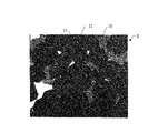
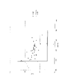
- Example 1 It is an SEM image of Example 1. It is a graph which plotted the magnetic property of each experimental example.
- the RTB-based permanent magnet of the present invention can be an RTB-based sintered magnet.
- composition The composition of the RTB-based sintered magnet will be described.
- R is a rare earth element.
- R contains cerium (Ce).
- Ce cerium
- the raw material cost is reduced.
- neodymium (Nd) and praseodymium (Pr) are selected as R1. It is preferable to contain seeds or more.
- T is Fe and Co.
- B is boron.
- the RTB-based sintered magnet contains one or more selected from aluminum (Al), copper (Cu), gallium (Ga) and Zr (zirconium). Two or more kinds may be included.
- the content of each element in the RTB-based sintered magnet will be described. Unless otherwise specified, the content of each element shown below is the content when the entire RTB-based sintered magnet is 100% by mass.
- the total content of R is 31.3% by mass or more and 34.0% by mass or less, assuming that the entire RTB-based sintered magnet is 100% by mass. It may be 32.0% by mass or more and 34.0% by mass or less. If the total content of R is too small, HcJ will decrease. If the total content of R is too large, Br will decrease.
- the content of B is 0.80% by mass or more and 0.90% by mass or less. It may be 0.80% by mass or more and 0.89% by mass or less, and may be 0.80% by mass or more and 0.86% by mass or less. If the content of B is too small, Hk / HcJ will decrease. If the content of B is too high, HcJ will decrease. If the B content is too low, Hk / HcJ decreases because the 2-17 phase, which is a heterogeneous phase, is formed at the grain boundaries and Hk decreases.
- the Co content is 1.85% by mass or more and 3.00% by mass or less. It may be 1.85% by mass or more and 2.80% by mass or less, and may be 1.85% by mass or more and 2.40% by mass or less. Further, the Co content may be 1.91% by mass or more, or 2.00% by mass or more. Further, the Co content may be 1.85% by mass or more and 2.09% by mass or less, or may be 1.91% by mass or more and 2.09% by mass or less, and 1.91% by mass or more and 2 It may be 0.00% by mass or less. If the Co content is too low, the corrosion resistance will decrease. If the Co content is too high, HcJ will decrease.
- the content of Ga is 0% by mass or more and 0.10% by mass or less. That is, it does not have to contain Ga.
- the smaller the Ga content the easier it is for the magnetic properties and manufacturing stability to improve. If the Ga content is too high, the magnetic properties, especially HcJ, will deteriorate.
- the Al content is 0.03% by mass or more and 0.90% by mass or less. It may be 0.30% by mass or more and 0.90% by mass or less. If the Al content is too low, HcJ will decrease. If the Al content is too high, Br will decrease.
- the Cu content is 0% by mass or more and 0.25% by mass or less. That is, it does not have to contain Cu.
- the Cu content may be 0% by mass or more and 0.10% by mass or less. If the Cu content is too high, HcJ will decrease.
- the Zr content is 0% by mass or more and 0.60% by mass or less. That is, it does not have to contain Zr. It may be 0.40% by mass or more and 0.60% by mass or less. The smaller the Zr content, the more likely it is that abnormal grain growth will occur. Then, Hk / HcJ decreases due to the occurrence of abnormal grain growth. If the Zr content is too high, a heterogeneous 2-17 phase is formed at the grain boundaries, resulting in a decrease in Hk / HcJ.
- the content of Ce (Ce / TRE) with respect to the total content of R (TRE) is 15% by mass or more and 25% by mass or less. It may be 16% by mass or more and 24% by mass or less. If Ce / TRE is too small, the raw material cost will not be sufficiently reduced. This is because the advantage that Ce is cheaper than other rare earth elements is offset by the disadvantage that the manufacturing process becomes complicated by increasing the types of raw material metals containing rare earth elements. If Ce / TRE is too large, HcJ will decrease.
- the total content of heavy rare earth elements contained as R may be 0% by mass or more and 0.10% by mass or less.
- the higher the content of heavy rare earth elements the easier it is for Br to decrease.
- heavy rare earth elements are more likely to enter the RT phase 13 than the main phase 11 described later.
- the RTB-based sintered magnet has a fine structure in which it is difficult to obtain suitable magnetic characteristics.
- Heavy rare earth elements refer to Gd, Tb, Dy, Ho, Er, Tm, Yb, and Lu.
- Yttrium (Y) and lanthanum (La) are not substantially contained as R.
- Substantially free of Y and La means that the content of Y with respect to R and the content of La with respect to R are 0.5% by mass or less in total.
- Y and La are substantially contained, it becomes difficult to form the RT phase described later, and it becomes difficult to obtain the effect of improving HcJ by the RT phase.
- the anisotropic magnetic field of the main phase particles tends to decrease.
- La the anisotropic magnetic field of the main phase particles tends to decrease.
- Fe is a substantial residue in the components of the RTB-based sintered magnet.
- the fact that Fe is a substantial balance means that Fe and unavoidable impurities are the only elements contained in the group other than the group consisting of R, B, Co, Ga, Al, Cu and Zr.
- the content of unavoidable impurities may be 0.5% by mass or less (including 0) in total with respect to the RTB-based sintered magnet.
- the Cu content is preferably around 0.05% by mass, specifically, 0.02% by mass or more and 0.08% by mass or less.
- the content of other elements is within the above range and the content of Cu is in the vicinity of 0.05%, the wettability of the R-rich phase during heat treatment is improved.
- the coverage of the main phase particles by the R-rich phase is increased, magnetic separation between the main phase particles is promoted, and HcJ is improved.
- the amount of Cu added is too small or too large, the wettability is lowered and HcJ is also lowered.
- FIG. 1 is a reflected electron image obtained by observing a cross section of Example 1 described later with a field emission scanning electron microscope (FE-SEM).
- FE-SEM field emission scanning electron microscope
- the reflected electron image obtained by observing with FE-SEM may be simply referred to as an SEM image.
- the main phase particles 11 and a plurality of types of grain boundary phases existing at the grain boundaries can be seen as shown in FIG.
- the plurality of grain boundary phases each have a shade of color according to the composition and a shape according to the crystal system.
- the composition is clarified by point-analyzing each grain boundary phase using an energy dispersive X-ray spectroscope (EDS), an electron probe microanalyzer (EPMA), a transmission electron microscope (TEM), etc. attached to the FE-SEM. By doing so, it is possible to identify what kind of grain boundary phase they are.
- EDS energy dispersive X-ray spectroscope
- EPMA electron probe microanalyzer
- TEM transmission electron microscope
- each grain boundary phase may be confirmed by a transmission electron microscope (TEM). By confirming the crystal structure of each grain boundary phase by TEM, each grain boundary phase can be specified more clearly.
- TEM transmission electron microscope
- the RTB-based sintered magnet 1 includes a grain boundary existing between the main phase particles 11 and the main phase particles 11.
- the main phase particle 11 is composed of an R 2 T 14 B compound.
- the R 2 T 14 B compound is a compound having a crystal structure composed of R 2 T 14 B type tetragonal crystals.
- the main phase particles 11 are black in the SEM image.
- the size of the main phase particles 11 is not particularly limited, but the equivalent circle diameter is approximately 1.0 ⁇ m to 10.0 ⁇ m.
- the grain boundaries include multi-particle boundaries and two-particle boundaries.
- a multi-particle grain boundary is a grain boundary surrounded by three or more main phase particles, and a two-particle grain boundary is a grain boundary existing between two adjacent main phase particles.
- the grain boundaries include at least two types of grain boundary phases.
- the RT phase 13 and the R rich phase 15 are included. Comparing the brightness of the main phase particles 11, the RT phase 13, and the R rich phase 15 in the SEM image, the main phase particles 11 are the darkest and the R rich phase 15 is the brightest.
- the content ratio of R and T is approximately 1: 2 in terms of atomic number ratio. Specifically, the content of R is 20.0 at% or more and 40.0 at% or less, and the content of T is 55.0 at% or more and 80.0 at% or less.
- the R content may be 24.0 at% or more and 32.0 at% or less, and the T content may be 61.0 at% or more and 75.0 at% or less.
- the total content of elements other than R and T contained in the RT phase 13 is 10.0 at% or less.
- the total content of elements other than R and T contained in the RT phase 13 may be 0.5 at% or more and 8.0 at% or less.
- the content of elements other than R, T and R and T is the content excluding oxygen (O), carbon (C) and nitrogen (N).
- the R-rich phase 15 refers to a phase in which the R content is 40.0 at% or more and the T content is lower than that of the RT phase 13.
- the content of R may be 47.0 at% or more. There is no particular upper limit to the R content, but the R content may be 68.0 at% or less.
- the T content may be 55.0 at% or less, or may be 50.0 at% or less. There is no particular lower limit to the T content, but the T content may be 31.0 at% or more.
- the contents of R and T are the contents excluding O, C and N.
- the present inventors have set the magnet composition within the above range in an RTB-based sintered magnet using Ce, which is a rare earth element that lowers HcJ as compared with Nd and Pr, although it is low in cost. As a result, it was found that a magnet having high Br, HcJ, Hk / HcJ, and corrosion resistance can be obtained.
- the R-rich phase 15 promotes magnetic separation between the main phase particles 11 and magnetic division between the main phase particles 11 and the RT phase 13.
- HcJ can be improved by including the R-rich phase 15.
- the magnet composition within the above range, the wettability between the main phase particles 11 and the R-rich phase 15 during the aging treatment is improved, and the coverage of the main phase particles 11 by the R-rich phase 15 is improved. ..
- the RT phase 13 tends to have a larger Ce content with respect to R than the main phase particles 11. This is to discharge Ce from the main phase particles 11 when the RT phase 13 is formed. As a result, the content of R other than Ce, specifically Nd, in the main phase particles 11 becomes high. Then, the anisotropic magnetic field in the main phase particles 11 becomes high. Further, the RT phase 13 itself contributes to magnetic division as a thick soft magnetic grain boundary.
- the magnet composition is within the above range, the above-mentioned effect of promoting magnetic fragmentation and the above-mentioned effect of discharging Ce from the main phase particles 11 are compatible.
- the result is an RTB-based sintered magnet with a high HcJ.
- the area ratio of the RT phase 13 to the grain boundaries may be 0.60 or more and 0.85 or less.
- the area ratio of the R-rich phase 15 to the grain boundaries is not particularly limited, but it is preferable that the portion of the grain boundaries other than the RT phase 13 is the R-rich phase 15. Specifically, the area ratio of the phases other than the R-rich phase 15 and the RT phase 13 to the grain boundaries is preferably 10.0% or less (including 0%).
- the area of the observation range of the SEM image for calculating the above area ratio is not particularly limited, but is set to a sufficiently wide range for calculating the above area ratio.
- the area of the observation range may be 0.01 mm 2 or more.
- the method for manufacturing an RTB-based sintered magnet has the following steps.
- A Alloy preparation step for producing an alloy for RTB-based sintered magnets (raw material alloy)
- Crushing step for crushing the raw material alloy c
- Sintering step of sintering a molded body to obtain an RTB-based sintered magnet e
- Aging treatment step of aging the RTB-based sintered magnet f
- RTB-based firing Processing process for processing a binding magnet
- Grain boundary diffusion process for diffusing heavy rare earth elements in the grain boundaries of an RTB-based sintered magnet
- h Surface treatment for an RTB-based sintered magnet Processing process
- Alloy preparation process Prepare an alloy for RTB-based sintered magnets (alloy preparation step).
- alloy preparation step the strip casting method will be described as an example of the alloy preparation method, but the alloy preparation method is not limited to the strip casting method.
- rare earth metals pure iron, pure cobalt, compounds such as ferroboron (FeB), and alloys such as rare earth alloys can be used.
- the casting method for casting the raw metal For example, an ingot casting method, a strip casting method, a book mold method, a centrifugal casting method, and the like can be mentioned. If the obtained raw material alloy has solidification segregation, it may be homogenized (solution treatment) as necessary.
- the pulverization step may be performed in two steps, a coarse pulverization step of pulverizing until the particle size is about several hundred ⁇ m to several mm, and a fine pulverization step of pulverizing until the particle size is about several ⁇ m. It may be performed in one step of only the fine pulverization step.
- the raw material alloy is roughly pulverized until the particle size is about several hundred ⁇ m to several mm (coarse pulverization step). As a result, a coarsely pulverized powder of the raw material alloy is obtained.
- coarse pulverization for example, after hydrogen is occluded in a raw material alloy, hydrogen is released based on the difference in the amount of hydrogen occluded between different phases, and dehydrogenation is performed to cause self-destructive pulverization (hydrogen storage pulverization). ) Can be done.
- the conditions for dehydrogenation are not particularly limited, but dehydrogenation is performed, for example, at 300 to 650 ° C. in an Ar flow or in a vacuum.
- the method of coarse crushing is not limited to the above hydrogen storage crushing.
- coarse pulverization may be performed using a coarse pulverizer such as a stamp mill, a jaw crusher, or a brown mill in an atmosphere of an inert gas.
- the atmosphere of each step from the coarse crushing step to the sintering step described later is an atmosphere of low oxygen concentration.
- the oxygen concentration is adjusted by controlling the atmosphere in each manufacturing process. If the oxygen concentration in each manufacturing process is high, rare earth elements in the alloy powder obtained by crushing the raw material alloy are oxidized to generate R oxide. The R oxide is not reduced during sintering and is deposited at the grain boundaries as it is in the form of R oxide. As a result, the coercive force HcJ of the obtained RTB-based sintered magnet tends to decrease. Therefore, for example, it is preferable to carry out each step (fine pulverization step, molding step) in an atmosphere having an oxygen concentration of 100 ppm or less.
- the D50 of the particles contained in the finely pulverized powder is not particularly limited.
- D50 may be 1.0 ⁇ m or more and 10.0 ⁇ m or less.
- the fine pulverization is carried out by further pulverizing the coarsely pulverized powder using a fine pulverizer such as an air flow type pulverizer (jet mill) while appropriately adjusting conditions such as the pulverization time.
- a fine pulverizer such as an air flow type pulverizer (jet mill)
- jet mill releases high-pressure inert gas (for example, He gas, N 2 gas, Ar gas) from a narrow nozzle to generate a high-speed gas flow, and this high-speed gas flow produces coarsely pulverized powder of the raw material alloy.
- high-pressure inert gas for example, He gas, N 2 gas, Ar gas
- a lubricant for example, an organic lubricant or a solid lubricant may be added.
- the organic lubricant include oleic acid amide, lauric acid amide, zinc stearate and the like.
- the solid lubricant include graphite and the like.
- the finely pulverized powder is molded into a desired shape (molding process).
- the finely pulverized powder is filled in a mold arranged in a magnetic field and pressurized to form the finely pulverized powder to obtain a molded product.
- a molding aid may be added during molding. There are no particular restrictions on the type of molding aid. The above lubricant may be used.
- the pressure at the time of pressurization may be, for example, 30 MPa or more and 300 MPa or less.
- the applied magnetic field may be, for example, 1.0 T or more and 5.0 T or less.
- the applied magnetic field is not limited to the static magnetic field, and may be a pulsed magnetic field. Further, a static magnetic field and a pulsed magnetic field can be used in combination.
- the shape of the molded body obtained by molding the finely pulverized powder is not particularly limited, and for example, a rectangular parallelepiped, a flat plate, a columnar shape, a ring shape, a C type, etc. It can be shaped according to the shape.
- the obtained molded body is sintered in a vacuum or an inert gas atmosphere to obtain an RTB-based sintered magnet (sintering step).
- the sintering temperature needs to be adjusted according to various conditions such as composition, pulverization method, difference in particle size and particle size distribution.
- the sintering temperature is not particularly limited, but may be, for example, 950 ° C. or higher and 1100 ° C. or lower.
- the sintering time is not particularly limited, but may be, for example, 2 hours or more and 10 hours or less.
- the atmosphere at the time of sintering For example, it may be an inert gas atmosphere or a vacuum atmosphere of less than 100 Pa.
- the RTB-based sintered magnet is aged (aging treatment step). After sintering, the obtained RTB-based sintered magnet is subjected to aging treatment at a temperature lower than that at the time of sintering.
- the aging temperature may be 400 ° C. or higher and 650 ° C. or lower, and the aging time may be 10 minutes or longer and 300 minutes or lower.
- an inert gas atmosphere having a pressure higher than the atmospheric pressure for example, He gas or Ar gas
- the aging treatment step may be performed after the processing step described later.
- the obtained RTB-based sintered magnet may be processed into a desired shape as needed (processing step).
- processing step examples include shape processing such as cutting and grinding, and chamfering processing such as barrel polishing.
- Heavy rare earth elements may be further diffused to the grain boundaries of the processed RTB-based sintered magnet (grain boundary diffusion step).
- grain boundary diffusion step There are no particular restrictions on the method of grain boundary diffusion. For example, it may be carried out by applying a compound containing a heavy rare earth element to the surface of an RTB-based sintered magnet by coating or vapor deposition, and then performing a heat treatment. Further, the RTB-based sintered magnet may be heat-treated in an atmosphere containing vapors of heavy rare earth elements. The grain boundary diffusion can further improve the HcJ of the RTB-based sintered magnet.
- the RTB-based sintered magnet obtained by the above steps may be subjected to surface treatment such as plating, resin coating, oxidation treatment, or chemical conversion treatment (surface treatment step). Thereby, the corrosion resistance can be further improved.
- a processing step a grain boundary diffusion step, and a surface treatment step are performed, but these steps do not necessarily have to be performed.
- the RT-B-based sintered magnet obtained as described above is an RT-B-based sintered magnet having good corrosion resistance such as Br, HcJ, Hk / HcJ while containing Ce.
- the present invention is not limited to the above embodiment, and can be variously modified within the scope of the present invention.
- the permanent magnet according to the present invention may be manufactured by hot working.
- the RTB-based permanent magnet of the present invention can be used for general RTB-based permanent magnets. For example, it can be used for a rotating machine of an automobile.
- a raw material metal containing a predetermined element was prepared.
- raw material metals Nd, Pr, Ce, Fe, Co, FeB, Al, Cu, Zr and Ga having a purity of 99.9% were prepared.
- RTB-based sintered magnets having the compositions shown in Tables 1 to 8, and a thin plate-shaped raw material alloy was prepared by a strip casting method. ..
- the raw material alloy obtained in the alloy preparation step was pulverized to obtain an alloy powder.
- the pulverization was performed in two stages of coarse pulverization and fine pulverization.
- Coarse pulverization was performed by hydrogen storage pulverization. After occluding hydrogen in the raw material alloy at 600 ° C., dehydrogenation was performed at 600 ° C. for 3 hours in an Ar flow or in vacuum.
- coarse pulverization an alloy powder having a particle size of about several hundred ⁇ m to several mm was obtained.
- Fine pulverization was carried out in a high-pressure nitrogen gas atmosphere using a jet mill after adding 0.1 part by mass of oleic acid amide as a lubricant to 100 parts by mass of the alloy powder obtained by coarse pulverization and mixing. .. Fine pulverization was performed until the D50 of the alloy powder became about 3.5 ⁇ m.
- the mixed powder obtained by the pulverization step was molded in a magnetic field to obtain a molded product. After the mixed powder was filled in a mold arranged between the electromagnets, it was formed by pressurizing it while applying a magnetic field with the electromagnets. Specifically, the mixed powder was compacted at a pressure of 110 MPa in a magnetic field of 2.2 T. The direction in which the magnetic field was applied was perpendicular to the pressing direction.
- Example 28a had a sintering temperature of 980 ° C., and Examples 28b and 28c had a sintering temperature of 990 ° C. to obtain a sintered body.
- the obtained sintered body was subjected to aging treatment to obtain an RTB-based sintered magnet.
- the aging treatment was carried out at an aging temperature of 600 ° C. and an aging time of 1 hour.
- the atmosphere at the time of aging treatment was Ar atmosphere.
- composition of the RTB-based sintered magnet finally obtained in each Example and Comparative Example is the composition shown in Tables 1 to 9, which is the fluorescent X-ray analysis method and inductively coupled plasma mass. It was confirmed by composition analysis by analytical method (ICP method) and gas analysis.
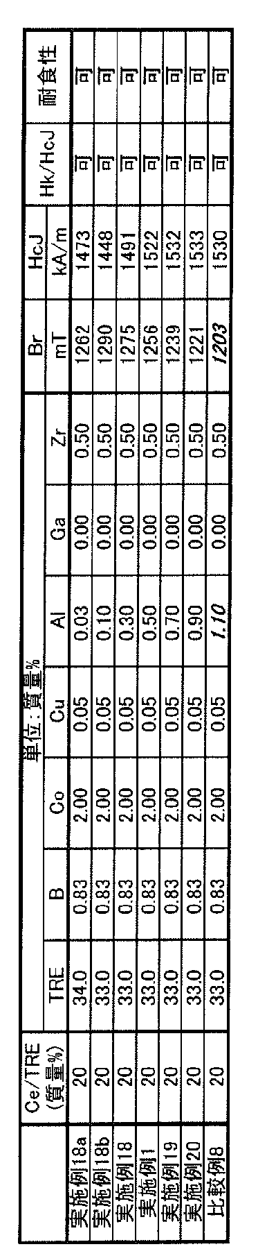
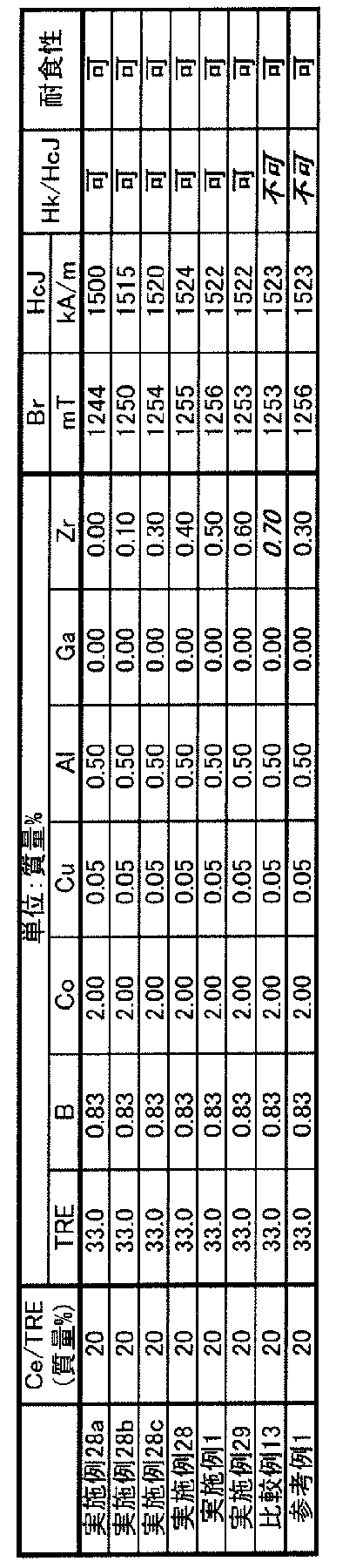
- the magnetic properties of the RTB-based sintered magnets of each Example and Comparative Example were measured using a BH tracer. Specifically, Br, HcJ, and Hk / HcJ were measured at room temperature. The results are shown in Tables 1-9. Br was good when it was 1220 mT or more. The case where HcJ exceeds 1445 kA / m is good, and the case where HcJ is 1450 kA / m or more is further good. It was evaluated whether Hk / HcJ was 95% or more. In Tables 1 to 9, the case where it is 95% or more is acceptable, and the case where it is less than 95% is not acceptable.
- Corrosion resistance tests were performed on the RTB-based sintered magnets of each Example and Comparative Example.
- the corrosion resistance test was carried out by a PCT test (pressure cooker test: Pressure Cooker Test) under saturated steam pressure. Specifically, the mass change before and after the test was measured by placing the RTB-based sintered magnet in an environment of 2 atm and 100% RH for 1000 hours. It was evaluated whether or not the mass reduction per surface area of the RTB-based sintered magnet was 3 mg / cm 2 or less. In Tables 1 to 9, cases of 3 mg / cm 2 or less were allowed, and cases of more than 3 mg / cm 2 were not allowed.
- each of the examples having a composition within the above range had good Br, HcJ, Hk / HcJ and corrosion resistance.
- any one or more of Br, HcJ, Hk / HcJ and corrosion resistance was not good.
- Example 28c and Reference Example 1 in Table 8 are experimental examples in which a sintered body was produced under the same conditions except for the sintering temperature.
- Example 28c is an example in which the content of Zr is reduced as compared with Example 28 and the like, and at the same time, the sintering temperature is lowered.
- Example 28c since an appropriate sintering temperature was selected according to the composition, abnormal grain growth did not occur and Hk / HcJ was good.
- Reference Example 1 is a reference example in which the Zr content was reduced as compared with Example 28 and the like, but the sintering temperature was not lowered at the same time.
- an appropriate sintering temperature was not selected according to the composition, abnormal grain growth occurred and Hk / HcJ decreased.
- FIG. 2 is a drawing plotted on a graph in which the horizontal axis is HcJ and the vertical axis is Br for all the examples and all the comparative examples in which Br or HcJ is not good. It can be seen from FIG. 2 that the magnet composition needs to be within a specific range in order to set Br to 1220 mT or more, HcJ to be larger than 1445 kA / m, and other characteristics to be good.
- the microstructure was confirmed for all the examples, and the main phase particles made of the R 2 T 14 B compound and the grain boundaries were included, and the grain boundaries contained the RT phase, and the R It was confirmed that the content of Ce with respect to R in the -T phase was higher than that in the main phase particles.
Landscapes
- Engineering & Computer Science (AREA)
- Power Engineering (AREA)
- Chemical & Material Sciences (AREA)
- Manufacturing & Machinery (AREA)
- Crystallography & Structural Chemistry (AREA)
- Inorganic Chemistry (AREA)
- Mechanical Engineering (AREA)
- Materials Engineering (AREA)
- Metallurgy (AREA)
- Organic Chemistry (AREA)
- Hard Magnetic Materials (AREA)
Abstract
Description
R(希土類元素)と、T(FeおよびCo)と、B(ホウ素)と、さらにAl、Cu、GaおよびZrから選択される1種以上と、を含むR-T-B系永久磁石であって、
RはCeを含み、
Rの合計含有量が31.3質量%以上34.0質量%以下、
Coの含有量が1.85質量%以上3.00質量%以下、
Bの含有量が0.80質量%以上0.90質量%以下、
Alの含有量が0.03質量%以上0.90質量%以下、
Cuの含有量が0質量%以上0.25質量%以下、
Gaの含有量が0質量%以上0.10質量%以下、
Zrの含有量が0質量%以上0.60質量%以下、
Feの含有量が実質的な残部であり、
Rに対するCeの含有量が15質量%以上25質量%以下である。
R-T-B系焼結磁石の組成について説明する。Rは希土類元素である。Rはセリウム(Ce)を含む。RがCeを含むことで、原料コストが低下する。また、R-T-B系焼結磁石の原料コストおよびR-T-B系焼結磁石の磁気特性を好適に制御するため、Rとしてネオジム(Nd)およびプラセオジム(Pr)から選択される1種以上を含むことが好ましい。
以下、R-T-B系焼結磁石1について、図1を用いて説明する。なお、図1は後述する実施例1の断面を電界放射型走査型電子顕微鏡(FE-SEM)で観察して得られた反射電子像である。FE-SEMで観察して得られた反射電子像のことを単にSEM画像と呼ぶ場合がある。
以下、R-T-B系焼結磁石を製造する方法の一例について説明する。R-T-B系焼結磁石を製造する方法は、以下の工程を有する。
(b)原料合金を粉砕する粉砕工程
(c)得られた合金粉末を成形する成形工程
(d)成形体を焼結し、R-T-B系焼結磁石を得る焼結工程
(e)R-T-B系焼結磁石を時効処理する時効処理工程
(f)R-T-B系焼結磁石を加工する加工工程
(g)R-T-B系焼結磁石の粒界に重希土類元素を拡散させる粒界拡散工程
(h)R-T-B系焼結磁石に表面処理する表面処理工程
R-T-B系焼結磁石用合金を準備する(合金準備工程)。以下、合金準備方法の一例としてストリップキャスティング法について説明するが、合金準備方法はストリップキャスティング法に限定されない。
原料合金を作製した後、原料合金を粉砕する(粉砕工程)。粉砕工程は、粒径が数百μm~数mm程度になるまで粉砕する粗粉砕工程と、粒径が数μm程度になるまで微粉砕する微粉砕工程との2段階で行ってもよいが、微粉砕工程のみの1段階で行ってもよい。
原料合金を粒径が数百μm~数mm程度になるまで粗粉砕する(粗粉砕工程)。これにより、原料合金の粗粉砕粉末を得る。粗粉砕は、例えば原料合金に水素を吸蔵させた後、異なる相間の水素吸蔵量の相違に基づいて水素を放出させ、脱水素を行なうことで自己崩壊的な粉砕を生じさせること(水素吸蔵粉砕)によって行うことができる。脱水素の条件には特に制限はないが、例えば300~650℃、Arフロー中または真空中で脱水素を行う。
原料合金を粗粉砕した後、得られた原料合金の粗粉砕粉末を平均粒子径が数μm程度になるまで微粉砕する(微粉砕工程)。これにより、原料合金の微粉砕粉末を得ることができる。微粉砕粉末に含まれる粒子のD50には特に制限はない。例えば、D50が1.0μm以上10.0μm以下であってもよい。
微粉砕粉末を目的の形状に成形する(成形工程)。成形工程では、微粉砕粉末を、磁場中に配置された金型内に充填して加圧することによって、微粉砕粉末を成形し、成形体を得る。このとき、磁場を印加しながら成形することで、微粉砕粉末の結晶軸を特定の方向に配向させた状態で成形することができる。得られる成形体は、特定方向に配向するので、より磁性の強い異方性を有するR-T-B系焼結磁石が得られる。成形時に、成形助剤を添加してもよい。成形助剤の種類には特に制限はない。上記の潤滑剤を用いてもよい。
得られた成形体を真空または不活性ガス雰囲気中で焼結し、R-T-B系焼結磁石を得る(焼結工程)。焼結温度は、組成、粉砕方法、粒度と粒度分布の違い等、諸条件により調整する必要がある。焼結温度には特に制限はないが、例えば950℃以上1100℃以下としてもよい。焼結時間には特に制限はないが、例えば2時間以上10時間以下としてもよい。焼結時の雰囲気には特に制限はない。例えば、不活性ガス雰囲気としてもよく、100Pa未満の真空雰囲気としてもよい。
成形体を焼結した後、R-T-B系焼結磁石を時効処理する(時効処理工程)。焼結後、得られたR-T-B系焼結磁石を焼結時よりも低い温度でR-T-B系焼結磁石に時効処理を施す。
得られたR-T-B系焼結磁石は、必要に応じて所望の形状に加工してもよい(加工工程)。加工方法は、例えば切断、研削などの形状加工や、バレル研磨などの面取り加工などが挙げられる。
加工されたR-T-B系焼結磁石の粒界に対して、さらに重希土類元素を拡散させてもよい(粒界拡散工程)。粒界拡散の方法には特に制限はない。例えば、塗布または蒸着等により重希土類元素を含む化合物をR-T-B系焼結磁石の表面に付着させた後に熱処理を行うことで実施してもよい。また、重希土類元素の蒸気を含む雰囲気中でR-T-B系焼結磁石に対して熱処理を行うことで実施してもよい。粒界拡散により、R-T-B系焼結磁石のHcJをさらに向上させることができる。
以上の工程により得られたR-T-B系焼結磁石は、めっきや樹脂被膜や酸化処理、化成処理などの表面処理を施してもよい(表面処理工程)。これにより、耐食性をさらに向上させることができる。
原料合金として、所定の元素を含む原料金属を準備した。原料金属としては、それぞれ純度99.9%であるNd、Pr、Ce、Fe、Co、FeB、Al、Cu、ZrおよびGaを準備した。
合金準備工程により得られた原料合金を粉砕し、合金粉末を得た。粗粉砕と微粉砕との2段階で粉砕を行った。粗粉砕は、水素吸蔵粉砕により行った。原料合金に対して水素を600℃で吸蔵させた後、Arフロー中または真空中、600℃で3時間、脱水素を行った。粗粉砕により、数百μm~数mm程度の粒径の合金粉末を得た。
粉砕工程により得られた混合粉末を磁場中で成形して成形体を得た。混合粉末を電磁石の間に配置された金型内に充填した後に、電磁石により磁場を印加しながら加圧して成形した。具体的には、混合粉末を2.2Tの磁場中、110MPaの圧力で圧粉成形した。磁場を印加する方向はプレス方向と垂直な方向とした。
得られた成形体を焼結して焼結体を得た。特に記載がない場合、焼結温度を1000℃、焼結時間を8時間として焼結体を得た。焼結時の雰囲気は真空雰囲気とした。
得られた焼結体に時効処理を行いR-T-B系焼結磁石を得た。時効処理は時効温度600℃、時効時間1時間で行った。時効処理時の雰囲気はAr雰囲気とした。
各実施例および比較例において最終的に得られたR-T-B系焼結磁石の組成が表1~表9に示す組成となっていることは、蛍光X線分析法、誘導結合プラズマ質量分析法(ICP法)、およびガス分析により組成分析することで確認した。







11・・・主相粒子
13・・・R-T相
15・・・Rリッチ相
Claims (5)
- R(希土類元素)と、T(FeおよびCo)と、B(ホウ素)と、さらにAl、Cu、GaおよびZrから選択される1種以上と、を含むR-T-B系永久磁石であって、
RはCeを含み、
Rの合計含有量が31.3質量%以上34.0質量%以下、
Coの含有量が1.85質量%以上3.00質量%以下、
Bの含有量が0.80質量%以上0.90質量%以下、
Alの含有量が0.03質量%以上0.90質量%以下、
Cuの含有量が0質量%以上0.25質量%以下、
Gaの含有量が0質量%以上0.10質量%以下、
Zrの含有量が0質量%以上0.60質量%以下、
Feの含有量が実質的な残部であり、
Rに対するCeの含有量が15質量%以上25質量%以下であるR-T-B系永久磁石。 - R2T14B化合物からなる主相粒子と、粒界と、を含み、前記粒界にR-T相が含まれる請求項1に記載のR-T-B系永久磁石。
- 前記R-T相のRに対するCeの含有量は前記主相粒子よりも多いことを特徴とする請求項2に記載のR-T-B系永久磁石。
- 重希土類元素の合計含有量が0質量%以上0.10質量%以下である請求項1から3のいずれかに記載のR-T-B系永久磁石。
- Coの含有量が1.85質量%以上2.09質量%以下である請求項1から4のいずれかに記載のR-T-B系永久磁石。
Priority Applications (3)
| Application Number | Priority Date | Filing Date | Title |
|---|---|---|---|
| JP2022568124A JP7676444B2 (ja) | 2020-12-09 | 2021-11-10 | R-t-b系永久磁石 |
| US18/266,080 US20240047103A1 (en) | 2020-12-09 | 2021-11-10 | R-t-b based permanent magnet |
| CN202180082842.4A CN116600916A (zh) | 2020-12-09 | 2021-11-10 | R-t-b系永久磁铁 |
Applications Claiming Priority (2)
| Application Number | Priority Date | Filing Date | Title |
|---|---|---|---|
| JP2020204546 | 2020-12-09 | ||
| JP2020-204546 | 2020-12-09 |
Publications (1)
| Publication Number | Publication Date |
|---|---|
| WO2022123992A1 true WO2022123992A1 (ja) | 2022-06-16 |
Family
ID=81974377
Family Applications (1)
| Application Number | Title | Priority Date | Filing Date |
|---|---|---|---|
| PCT/JP2021/041377 Ceased WO2022123992A1 (ja) | 2020-12-09 | 2021-11-10 | R-t-b系永久磁石 |
Country Status (4)
| Country | Link |
|---|---|
| US (1) | US20240047103A1 (ja) |
| JP (1) | JP7676444B2 (ja) |
| CN (1) | CN116600916A (ja) |
| WO (1) | WO2022123992A1 (ja) |
Cited By (1)
| Publication number | Priority date | Publication date | Assignee | Title |
|---|---|---|---|---|
| JP2023070057A (ja) * | 2021-11-05 | 2023-05-18 | 信越化学工業株式会社 | 異方性希土類焼結磁石及びその製造方法 |
Citations (2)
| Publication number | Priority date | Publication date | Assignee | Title |
|---|---|---|---|---|
| JP2020095992A (ja) * | 2017-03-30 | 2020-06-18 | Tdk株式会社 | 焼結磁石及び回転機 |
| JP2020095991A (ja) * | 2017-03-30 | 2020-06-18 | Tdk株式会社 | 焼結磁石及び回転機 |
Family Cites Families (4)
| Publication number | Priority date | Publication date | Assignee | Title |
|---|---|---|---|---|
| JP2003525345A (ja) | 1999-02-12 | 2003-08-26 | ゼネラル・エレクトリック・カンパニイ | プラセオジムに富む鉄−ホウ素−希土類組成物、それから作製した永久磁石、および作製方法 |
| CN107275025B (zh) | 2016-04-08 | 2019-04-02 | 沈阳中北通磁科技股份有限公司 | 一种含铈钕铁硼磁钢及制造方法 |
| JP7314513B2 (ja) * | 2018-07-09 | 2023-07-26 | 大同特殊鋼株式会社 | RFeB系焼結磁石 |
| CN108922710B (zh) | 2018-07-18 | 2020-03-20 | 钢铁研究总院 | 一种高韧性、高矫顽力含Ce烧结稀土永磁体及其制备方法 |
-
2021
- 2021-11-10 WO PCT/JP2021/041377 patent/WO2022123992A1/ja not_active Ceased
- 2021-11-10 US US18/266,080 patent/US20240047103A1/en active Pending
- 2021-11-10 CN CN202180082842.4A patent/CN116600916A/zh active Pending
- 2021-11-10 JP JP2022568124A patent/JP7676444B2/ja active Active
Patent Citations (2)
| Publication number | Priority date | Publication date | Assignee | Title |
|---|---|---|---|---|
| JP2020095992A (ja) * | 2017-03-30 | 2020-06-18 | Tdk株式会社 | 焼結磁石及び回転機 |
| JP2020095991A (ja) * | 2017-03-30 | 2020-06-18 | Tdk株式会社 | 焼結磁石及び回転機 |
Cited By (2)
| Publication number | Priority date | Publication date | Assignee | Title |
|---|---|---|---|---|
| JP2023070057A (ja) * | 2021-11-05 | 2023-05-18 | 信越化学工業株式会社 | 異方性希土類焼結磁石及びその製造方法 |
| JP7684255B2 (ja) | 2021-11-05 | 2025-05-27 | 信越化学工業株式会社 | 異方性希土類焼結磁石及びその製造方法 |
Also Published As
| Publication number | Publication date |
|---|---|
| JPWO2022123992A1 (ja) | 2022-06-16 |
| US20240047103A1 (en) | 2024-02-08 |
| CN116600916A (zh) | 2023-08-15 |
| JP7676444B2 (ja) | 2025-05-14 |
Similar Documents
| Publication | Publication Date | Title |
|---|---|---|
| US8123832B2 (en) | R-T-B system sintered magnet | |
| JP2015204390A (ja) | 永久磁石およびモータ | |
| US10186357B2 (en) | R-T-B based sintered magnet | |
| JP7424126B2 (ja) | R-t-b系永久磁石 | |
| US11387024B2 (en) | R-T-B based rare earth sintered magnet and method of producing R-T-B based rare earth sintered magnet | |
| US10192661B2 (en) | R—T—B based sintered magnet | |
| CN111724955B (zh) | R-t-b系永久磁铁 | |
| JP7676444B2 (ja) | R-t-b系永久磁石 | |
| CN118866495A (zh) | R-t-b系永久磁铁及其制造方法 | |
| CN111724961B (zh) | R-t-b系永久磁铁 | |
| JP7687822B2 (ja) | R-t-b系永久磁石 | |
| JP7664039B2 (ja) | R-t-b系永久磁石 | |
| JP4556727B2 (ja) | 希土類焼結磁石の製造方法 | |
| CN113838621A (zh) | R-t-b系永久磁铁及电动机 | |
| US12592330B2 (en) | R-T-B based permanent magnet | |
| JP2020161692A (ja) | R−t−b系永久磁石 | |
| JP7447573B2 (ja) | R-t-b系永久磁石 | |
| US20140311289A1 (en) | R-t-b based sintered magnet | |
| JP7315889B2 (ja) | R-t-b系永久磁石用合金およびr-t-b系永久磁石の製造方法 | |
| WO2023080171A1 (ja) | R-t-b系永久磁石 | |
| WO2023080169A1 (ja) | R-t-b系永久磁石 | |
| CN121938741A (zh) | R-t-b系永久磁体 | |
| JP2005286176A (ja) | R−t−b系焼結磁石及びその製造方法 |
Legal Events
| Date | Code | Title | Description |
|---|---|---|---|
| 121 | Ep: the epo has been informed by wipo that ep was designated in this application |
Ref document number: 21903096 Country of ref document: EP Kind code of ref document: A1 |
|
| ENP | Entry into the national phase |
Ref document number: 2022568124 Country of ref document: JP Kind code of ref document: A |
|
| WWE | Wipo information: entry into national phase |
Ref document number: 18266080 Country of ref document: US Ref document number: 202180082842.4 Country of ref document: CN |
|
| NENP | Non-entry into the national phase |
Ref country code: DE |
|
| 122 | Ep: pct application non-entry in european phase |
Ref document number: 21903096 Country of ref document: EP Kind code of ref document: A1 |