WO2022123945A1 - Bord, unité de haut-parleur, microphone et dispositif de traitement acoustique - Google Patents
Bord, unité de haut-parleur, microphone et dispositif de traitement acoustique Download PDFInfo
- Publication number
- WO2022123945A1 WO2022123945A1 PCT/JP2021/039790 JP2021039790W WO2022123945A1 WO 2022123945 A1 WO2022123945 A1 WO 2022123945A1 JP 2021039790 W JP2021039790 W JP 2021039790W WO 2022123945 A1 WO2022123945 A1 WO 2022123945A1
- Authority
- WO
- WIPO (PCT)
- Prior art keywords
- edge
- curve
- point
- peripheral edge
- groove
- Prior art date
Links
- 230000002093 peripheral effect Effects 0.000 claims description 75
- 230000007423 decrease Effects 0.000 claims description 4
- 238000010586 diagram Methods 0.000 description 21
- 230000000694 effects Effects 0.000 description 11
- 239000000463 material Substances 0.000 description 11
- 238000006073 displacement reaction Methods 0.000 description 10
- 230000004048 modification Effects 0.000 description 10
- 238000012986 modification Methods 0.000 description 10
- 238000006243 chemical reaction Methods 0.000 description 9
- 230000005855 radiation Effects 0.000 description 6
- 238000005096 rolling process Methods 0.000 description 6
- 230000006870 function Effects 0.000 description 5
- 229920000106 Liquid crystal polymer Polymers 0.000 description 4
- 239000004977 Liquid-crystal polymers (LCPs) Substances 0.000 description 4
- 239000004433 Thermoplastic polyurethane Substances 0.000 description 4
- 229920001971 elastomer Polymers 0.000 description 4
- 238000000034 method Methods 0.000 description 4
- 229920000139 polyethylene terephthalate Polymers 0.000 description 4
- 239000005020 polyethylene terephthalate Substances 0.000 description 4
- 230000002123 temporal effect Effects 0.000 description 4
- 229920002803 thermoplastic polyurethane Polymers 0.000 description 4
- 230000005520 electrodynamics Effects 0.000 description 3
- 210000003128 head Anatomy 0.000 description 3
- 229910052751 metal Inorganic materials 0.000 description 3
- 239000002184 metal Substances 0.000 description 3
- 230000002159 abnormal effect Effects 0.000 description 2
- 238000005452 bending Methods 0.000 description 2
- 230000008602 contraction Effects 0.000 description 2
- 238000013016 damping Methods 0.000 description 2
- 239000000806 elastomer Substances 0.000 description 2
- 229920003023 plastic Polymers 0.000 description 2
- 239000004033 plastic Substances 0.000 description 2
- -1 polyethylene terephthalate Polymers 0.000 description 2
- 230000001012 protector Effects 0.000 description 2
- 229920005989 resin Polymers 0.000 description 2
- 239000011347 resin Substances 0.000 description 2
- 238000003860 storage Methods 0.000 description 2
- 229920003002 synthetic resin Polymers 0.000 description 2
- 239000000057 synthetic resin Substances 0.000 description 2
- 210000003454 tympanic membrane Anatomy 0.000 description 2
- 229910000838 Al alloy Inorganic materials 0.000 description 1
- 229920000049 Carbon (fiber) Polymers 0.000 description 1
- 125000002066 L-histidyl group Chemical group [H]N1C([H])=NC(C([H])([H])[C@](C(=O)[*])([H])N([H])[H])=C1[H] 0.000 description 1
- 229910000861 Mg alloy Inorganic materials 0.000 description 1
- 235000002492 Rungia klossii Nutrition 0.000 description 1
- 244000117054 Rungia klossii Species 0.000 description 1
- 239000000853 adhesive Substances 0.000 description 1
- 230000001070 adhesive effect Effects 0.000 description 1
- XAGFODPZIPBFFR-UHFFFAOYSA-N aluminium Chemical compound [Al] XAGFODPZIPBFFR-UHFFFAOYSA-N 0.000 description 1
- 230000015572 biosynthetic process Effects 0.000 description 1
- 239000004917 carbon fiber Substances 0.000 description 1
- 238000005520 cutting process Methods 0.000 description 1
- 210000005069 ears Anatomy 0.000 description 1
- 239000004744 fabric Substances 0.000 description 1
- 239000000835 fiber Substances 0.000 description 1
- 230000009931 harmful effect Effects 0.000 description 1
- 239000002649 leather substitute Substances 0.000 description 1
- 239000000696 magnetic material Substances 0.000 description 1
- 238000004519 manufacturing process Methods 0.000 description 1
- VNWKTOKETHGBQD-UHFFFAOYSA-N methane Chemical compound C VNWKTOKETHGBQD-UHFFFAOYSA-N 0.000 description 1
- 239000000123 paper Substances 0.000 description 1
- 238000007789 sealing Methods 0.000 description 1
- 230000035945 sensitivity Effects 0.000 description 1
- 238000009751 slip forming Methods 0.000 description 1
- 230000005236 sound signal Effects 0.000 description 1
Images


Classifications
-
- H—ELECTRICITY
- H04—ELECTRIC COMMUNICATION TECHNIQUE
- H04R—LOUDSPEAKERS, MICROPHONES, GRAMOPHONE PICK-UPS OR LIKE ACOUSTIC ELECTROMECHANICAL TRANSDUCERS; DEAF-AID SETS; PUBLIC ADDRESS SYSTEMS
- H04R7/00—Diaphragms for electromechanical transducers; Cones
- H04R7/16—Mounting or tensioning of diaphragms or cones
- H04R7/18—Mounting or tensioning of diaphragms or cones at the periphery
- H04R7/20—Securing diaphragm or cone resiliently to support by flexible material, springs, cords, or strands
-
- H—ELECTRICITY
- H04—ELECTRIC COMMUNICATION TECHNIQUE
- H04R—LOUDSPEAKERS, MICROPHONES, GRAMOPHONE PICK-UPS OR LIKE ACOUSTIC ELECTROMECHANICAL TRANSDUCERS; DEAF-AID SETS; PUBLIC ADDRESS SYSTEMS
- H04R1/00—Details of transducers, loudspeakers or microphones
- H04R1/10—Earpieces; Attachments therefor ; Earphones; Monophonic headphones
- H04R1/1058—Manufacture or assembly
- H04R1/1075—Mountings of transducers in earphones or headphones
-
- H—ELECTRICITY
- H04—ELECTRIC COMMUNICATION TECHNIQUE
- H04R—LOUDSPEAKERS, MICROPHONES, GRAMOPHONE PICK-UPS OR LIKE ACOUSTIC ELECTROMECHANICAL TRANSDUCERS; DEAF-AID SETS; PUBLIC ADDRESS SYSTEMS
- H04R7/00—Diaphragms for electromechanical transducers; Cones
- H04R7/02—Diaphragms for electromechanical transducers; Cones characterised by the construction
- H04R7/12—Non-planar diaphragms or cones
-
- H—ELECTRICITY
- H04—ELECTRIC COMMUNICATION TECHNIQUE
- H04R—LOUDSPEAKERS, MICROPHONES, GRAMOPHONE PICK-UPS OR LIKE ACOUSTIC ELECTROMECHANICAL TRANSDUCERS; DEAF-AID SETS; PUBLIC ADDRESS SYSTEMS
- H04R2307/00—Details of diaphragms or cones for electromechanical transducers, their suspension or their manufacture covered by H04R7/00 or H04R31/003, not provided for in any of its subgroups
- H04R2307/204—Material aspects of the outer suspension of loudspeaker diaphragms
-
- H—ELECTRICITY
- H04—ELECTRIC COMMUNICATION TECHNIQUE
- H04R—LOUDSPEAKERS, MICROPHONES, GRAMOPHONE PICK-UPS OR LIKE ACOUSTIC ELECTROMECHANICAL TRANSDUCERS; DEAF-AID SETS; PUBLIC ADDRESS SYSTEMS
- H04R2307/00—Details of diaphragms or cones for electromechanical transducers, their suspension or their manufacture covered by H04R7/00 or H04R31/003, not provided for in any of its subgroups
- H04R2307/207—Shape aspects of the outer suspension of loudspeaker diaphragms
Definitions
- This disclosure relates to edges, speaker units, microphones and sound processing devices.
- Patent Document 1 describes a technique for reducing distortion of reproduced sound by forming an inner notch and an outer notch having a predetermined angular relationship on the edge.
- One of the purposes of this disclosure is to provide an edge, a speaker unit, a microphone and an acoustic processing device that improve sound quality.
- the present disclosure is, for example, An edge-shaped portion formed from the inner peripheral edge portion to the outer peripheral edge portion, It is formed in the edge shape part and has a groove part having a mountain part and a valley part, and has a groove part.
- the ridgeline of the valley of the groove is an edge extending in a continuously changing curve from the start point on the inner peripheral edge side to the end point on the outer peripheral edge side.
- the present disclosure is, for example, A diaphragm that is displaced by a drive signal and Has an edge that supports the diaphragm,
- the edge is An edge-shaped portion formed from the inner peripheral edge portion to the outer peripheral edge portion, It is formed in the edge shape part and has a groove part having a mountain part and a valley part, and has a groove part.
- the ridgeline of the valley of the groove is a speaker unit that extends in a continuously changing curve from the start point on the inner peripheral edge side to the end point on the outer peripheral edge side.
- the present disclosure is, for example, A diaphragm that is displaced by sound pressure and Has an edge that supports the diaphragm,
- the edge is An edge-shaped portion formed from the inner peripheral edge portion to the outer peripheral edge portion, It is formed in the edge shape part and has a groove part having a mountain part and a valley part, and has a groove part.
- the ridgeline of the valley portion of the groove is a microphone extending in a continuously changing curve from the start point on the inner peripheral edge side to the end point on the outer peripheral edge side.
- the present disclosure may be an acoustic processing device having the above-mentioned speaker unit or microphone.
- FIG. 1A and 1B are diagrams referenced when discussing issues to be considered in the present disclosure.
- FIG. 2 is a diagram to be referred to when explaining the problems to be considered in the present disclosure.
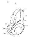
- FIG. 3 is a diagram for explaining a configuration example of headphones according to an embodiment.
- FIG. 4 is a diagram for explaining a configuration example of headphones according to an embodiment.
- 5A and 5B are diagrams for explaining a configuration example of the speaker unit according to the embodiment.
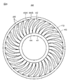
- FIG. 6 is a diagram for explaining a configuration example of an edge according to an embodiment.
- 7A and 7B are views for explaining an example of the cross-sectional shape of the rib according to the embodiment.
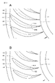
- FIG. 8 is a diagram for explaining an example of a curve drawn by a ridgeline of a valley portion according to an embodiment.
- FIG. 9 is a diagram for explaining the relationship between the depths of the mountain portion and the valley portion.
- FIG. 10 is a diagram for explaining the relationship between the depths of the mountain portion and the valley portion.
- FIG. 11 is a diagram for explaining a specific example of the relationship between the depths of the mountain portion and the valley portion.
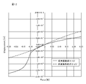
- FIG. 12 is a diagram for explaining an example of the effect obtained by the present embodiment.
- 13A and 13B are diagrams for explaining a modification.
- FIG. 14 is a diagram for explaining a modification.
- 17A and 17B are diagrams for explaining a modification.
- 18A to 18F are diagrams for explaining a modification.
- FIG. 19 is a diagram for explaining a microphone to which the present disclosure is applicable.
- the speaker unit used in the speaker device has a diaphragm that is displaced according to the drive signal.
- the diaphragm is attached to the frame via the edge.
- the sound quality of the reproduced sound reproduced by the speaker unit may be deteriorated due to the deformation of the edge when the diaphragm is displaced. This point will be described with reference to FIGS. 1A, 1B, and 2.
- the horizontal axis indicates the displacement and the vertical axis indicates the magnitude of the force (reaction force).
- FIGS. 1A and 1B are views showing the diaphragm (diaphragm 1) and the edge (edge 2) attached to the diaphragm 1 in a simplified manner. Further, the dotted line in FIGS. 1A and 1B indicates the position when the diaphragm 1 and the edge 2 are displaced.
- damperless speaker units are used for headphones and earphones.
- the diaphragm is attached to the frame via the edge.
- the edge has a damping effect on the diaphragm and a role of supporting the diaphragm, and the edge itself also has a function as a part of the diaphragm by vibrating.
- Such a configuration is very effective for making the speaker unit smaller and thinner, reducing the weight of the vibration system, and increasing the sound pressure sensitivity.
- the risk of abnormal vibration such as rolling and rolling is increased as compared with the speaker unit having a damper.
- ribs grooves
- This rib improves the bending strength in the direction in which the groove extends, but exhibits the effect of lowering the bending strength in the direction across the groove. This has the effect of reducing rolling and rolling while making the diaphragm easier to move back and forth.
- the reaction force generated when the diaphragm is displaced forward with the same amount of displacement and when it is displaced backward is different, that is, even if the same force is input, it is front and back.
- the amount of displacement is different, which can cause distortion in the reproduced sound.
- the linearity of the relationship between the displacement amount and the reaction force is not sufficient. This can also cause distortion in the reproduced sound. And, such a problem becomes remarkable at a large amplitude.
- some headphones open a part or most of the housing to open the space from the front of the speaker unit to the user. Many users prefer open headphones because they can listen to external sounds at the same time.
- the open type headphones have a lower sound pressure in the low frequency region than the closed type or semi-closed type headphones. If the amplitude is increased in order to prevent such a decrease in sound pressure, the above-mentioned asymmetry and non-linearity may become remarkable. In consideration of the above points, the details of the present disclosure will be described below with reference to the embodiments.
- headphones will be described as an example of the sound processing device.
- the present disclosure is also applicable to other sound processing devices such as earphones, hearing aids, and stationary speaker devices.
- FIG. 3 is a diagram (perspective view) for explaining the external configuration of the headphone 10.
- FIG. 4 is a diagram partially showing a state in which the headphone 10 is worn by the user.
- the headphone 10 has, for example, a slider 3, a hanger 4L, 4R, a housing 5L, 5R, ear pads 6L, 6R, and a headband 7.
- a driver unit 20R is provided inside the housing 5R.
- a driver unit having the same configuration as the driver unit 20R is also provided inside the housing 5L.
- Sliders 3 are provided at both ends of the headband 7.
- a hanger (hanger 4L or 4R) is attached to the joint portion at one end of the slider 3.
- the slider 3 is slidably configured along a guide member (not shown) that is fixed to both ends of the headband 7 and has an axis that coincides with the central axis of the headband 7.
- the hangers 4L and 4R can be moved so as to move away from or closer to the headband 7.
- the position of the slider 3 is adjusted according to the size of the head of the user (wearer), the distance between the ear and the crown, and the like.
- the user of the headphone 10 can obtain a wearing feeling according to his / her physical characteristics and taste.
- the storage space can be saved by keeping the slider 3 in the contracted state.
- the hangers 4L and 4R are provided at the tip of the slider 3 via a joint (not shown) to rotatably support the housings 5L and 5R.
- the housings 5L and 5R have a storage space inside, and store a driver unit that converts an electric signal into a sound wave and outputs it.
- the housings 5L and 5R are formed by using a synthetic resin such as plastic, for example.
- the housings 5L and 5R have the effect of obstructing the ingress and egress of air on the front and back sides of the diaphragm of the speaker, and the space from the front of the diaphragm to the eardrum of the user is sealed or the housing has acoustic resistance, a duct, etc. By sealing it, it also plays a role of efficiently transmitting the acoustic radiation on the front of the diaphragm to the user's eardrum.
- the ear pads 6L and 6R are provided on the surface of the housings 5L and 5R on the side facing the user's temporal region.
- the ear pads 6L and 6R function as a cushioning member between the housings 5L and 5R and the user's temporal region by interposing between the housings 5L and 5R and the user's temporal region. That is, in the ear pads 6L and 6R, when the headphones 10 are worn, the housings 5L and 5R made of a hard material that is not easily deformed come into direct contact with the user's ears and temporal region, causing discomfort and pain to the user. It is to prevent.
- the ear pads 6L and 6R have a structure in which a sponge or the like is covered with synthetic leather or cloth.
- the headband 7 is formed in a curved shape along the user's head, and supports the entire headphone 10 by touching the top of the user's head in the worn state.
- the headband 7 is made of a synthetic resin such as plastic, a metal, or the like, and has a predetermined rigidity and elasticity to provide flexibility. It should be noted that rubber or the like may be provided as a cushioning material on the inner surface of the headband 7 in contact with the crown of the user. Further, a hinge may be provided so that the headphone 10 can be folded in the center when the headphone 10 is carried.
- FIG. 5A is a front view of the driver unit 20R viewed from the sound radiation direction side (front side in the direction toward the drawing), and FIG. 5B is a cross section when the driver unit 20R is cut along the cutting line AA-AA in FIG. 5A. It is a figure.
- the driver unit 20R housed inside the housing 5R will be described, but the same configuration is applied to the driver unit housed inside the housing 5L.
- the driver unit 20R is, for example, a damperless electrodynamic speaker unit.
- the driver unit 20R includes, for example, a diaphragm 21, an edge 22, a diaphragm ring 23, a frame 24, and a magnetic circuit 25.
- the magnetic circuit 25 includes, for example, a voice coil 26, a bobbin 27, a yoke 28, a magnet 29, and a pole piece 30.
- the edge 22 and the diaphragm ring 23 are arranged around the diaphragm 21.
- the diaphragm 21 is connected to the diaphragm ring 23 via the edge 22.
- the diaphragm ring 23 is firmly fixed to the frame 24.
- the diaphragm 21 has a substantially circular shape in the front view and a dome shape in the cross-sectional view.
- rubber, fiber woven material such as paper and carbon fiber, metal such as aluminum and magnesium alloy, thermoplastic polyurethane elastomer (TPU), polyethylene terephthalate (PET), liquid crystal polymer film (LCP) and the like are used. Can be applied.
- the thickness of the diaphragm 21 is, for example, about 30 to 50 ( ⁇ m).
- the edge 22 has a shape that is substantially semicircular when viewed in cross section.
- a thermoplastic polyurethane elastomer (TPU), polyethylene terephthalate (PET), a liquid crystal polymer film (LCP), or the like can be applied.
- the edge 22 and the diaphragm 21 may be made of the same material (for example, the same resin material) or may be made of different materials.
- a rib 46 is formed on the edge 22. The details of the rib 46 will be described later.
- the diaphragm ring 23 and the frame 24 are made of resin, metal, or the like.
- the diaphragm ring 23 is used for the purpose of maintaining the shape when the diaphragm 21 and the edge 22 are molded.
- the configuration related to the diaphragm ring 23 may be omitted, or the edge 22 may be directly fixed to the frame 24.
- the magnetic circuit 25 vibrates the diaphragm 21 in the vertical direction in FIG. 5B by applying a force corresponding to the drive signal to the diaphragm 21. Due to the vibration of the diaphragm 21, sound is radiated from the opposite side of the magnetic circuit 25 to the diaphragm 21, and the radiated sound is heard by the user.
- the magnetic circuit 25 is firmly fixed to the frame 24. Even if a protector is prepared on the opposite side of the frame 24 to the diaphragm 21 and the protector is fixed to the frame 24 for the purpose of protecting the diaphragm 21 from contact by a user or a worker at the time of assembling the product. good.
- the voice coil 26 is connected to the diaphragm 21 using an adhesive, double-sided tape, or the like.
- the voice coil 26 vibrates in the vertical direction in FIG. 5B in response to the drive signal.
- the vibration of the voice coil 26 is transmitted to the diaphragm 21, so that the diaphragm 21 vibrates.
- the voice coil 26 is wound around the bobbin 27.
- the yoke 28 is made of, for example, a magnetic material.
- One end face of the ring-shaped magnet 29 is fixed on the flange portion of the yoke 28.
- the other end face ring-shaped (ring plate-shaped) pole piece 30 of the magnet 29 is overlapped.
- the voice coil 26 is arranged in the gap between the yoke 28 and the pole piece 30.
- FIG. 6 is a front view of the edge 22 as viewed from the sound radiation direction side.
- the edge 22 has a ring shape as a whole when viewed from the front.
- the edge 22 has a structure in which an inner flat portion 41, an edge shape portion 42, and an outer flat portion 43 are continuously formed from the inside. Further, the edge 22 has an inner peripheral edge portion 44 and an outer peripheral edge portion 45.
- Each of these configurations is made of the same material, but may be made of different materials.
- the inner flat portion 41 functions as a mounting portion used when, for example, a diaphragm 21 or a bobbin 27 is mounted. Further, the outer flat portion 43 functions as an attachment portion used when the edge 22 is attached to a predetermined position such as the diaphragm ring 23.
- the edge shape portion 42 is a convex portion that is convex in at least one direction.
- the edge-shaped portion 42 according to the present embodiment has a substantially semicircular cross-sectional shape and is a convex portion that is convex in one direction toward the radiation direction side of the sound.
- the edge shape portion 42 may have a shape that is convex in both the radiation direction side and the opposite side of the sound, or may be a shape that the convex direction changes from the middle.
- the inner peripheral edge portion 44 is a boundary portion between the inner flat portion 41 and the edge shape portion 42
- the outer peripheral edge portion 45 is a boundary portion between the outer flat portion 43 and the edge shape portion 42.
- the edge shape portion 42 is formed with a rib 46 that is recessed on the side opposite to the sound radiation direction side.
- a plurality of ribs 46 are formed at substantially equal intervals with respect to the edge shape portion 42.
- the uneven shape of the edge 22 formed by the rib 46 is also referred to as corrugation or the like.
- the rib 46 is formed together with the edge shape portion 42 and other portions using, for example, a mold. In FIG. 6, reference numerals are given only to some of the ribs 46.
- the rib 46 has a mountain portion 46A and a valley portion 46B.
- the mountain portion 46A means a portion of the rib 46 having the shallowest depth (the portion on the front side of the paper surface in FIG. 6).
- the valley portion 46B means a portion of the rib 46 having the deepest depth (a portion on the deepest side of the paper surface in FIG. 6).
- the rib 46 operates so as to follow the displacement of the diaphragm 21 and the expansion and contraction of the edge 22. Specifically, when the diaphragm 21 is displaced forward, the rib 46 operates so as to open, and when the diaphragm 21 operates backward, the rib 46 operates so as to close.
- the line formed by the valley portion 46B (hereinafter, appropriately referred to as the ridgeline of the valley portion 46B) is a predetermined position on the inner peripheral edge portion 44 side (hereinafter, appropriately referred to as a starting point) on the outer peripheral edge portion 45 side. (Hereinafter, appropriately referred to as an end point), it extends so as to draw a continuously changing curve.
- the start point and the end point are descriptions used for convenience of explanation, and the description does not limit the manufacturing method of the edge 22 and the like. Further, the number of start points and end points and the pattern of the arrangement position can be appropriately set. In the present embodiment, the start point is set on the inner peripheral edge portion 44, and the end point is set on the outer peripheral edge portion 45.
- Cross-sectional shape of rib The cross-sectional shape of the rib 46 may be, for example, a V-shape as shown in FIG. 7A, an arc shape as shown in FIG. 7B, or any other shape (rectangular shape, U-shape, etc.). It may be present or it may be a combination thereof.
- R1 Radius P1: Inner peripheral edge 44 radius P1: Start point of ridgeline of valley 46B
- R2 Radius P2 of outer peripheral edge 45: Arbitrary repeating pattern point P3 on R2: End point L1: P0 of ridgeline of valley 46B
- Straight line passing through P2 normal to R1 and R2
- D1 Angle formed by L1 and L2 (0 ° ⁇ D1 ⁇ 30 °)
- L3 Straight line passing through P1 and P3
- D2 Angle formed by L1 and L3 (D1 ⁇ D2 ⁇ 90 °) Are shown respectively.
- the curve drawn by the ridgeline of the valley 46B is defined as follows. First, a starting point P1 which is an intersection of the normal L1 with respect to the central portion of the edge 22 and the inner peripheral edge portion 44 is set.
- the normal L1 is not limited to the normal in a strict sense, but includes a line inclined to a predetermined degree (for example, within a range of 30 °) from the normal. That is, L2 is also included in the normals herein.
- a curve passing through the start point P1 is set, and the intersection of the curve and the outer peripheral edge portion 45 is set as the end point P3.
- the curve P1P3 passing through the start point P1 and the end point P3 satisfies the following conditions.
- the point on the curve P1P3 away from the starting point P1 is P4 (an example of the first point), and the angle formed by the normal line L1 (may be L2) and the tangent line L4 at P4 with respect to the curve P1P3 is the angle D3 (first point). Angle).
- a point further away from the start point P1 to P4 is designated as P5 (an example of the second point), and the angle formed by the normal line L1 (may be L2) and the tangent line L5 at P5 with respect to the curve P1P3 is D4. (Second angle).
- the curve P1P3 is a curve so as to satisfy D3 (first angle) ⁇ D4 (second angle), and the end point P3 is also set to satisfy the above condition.
- the curve P1P3 may be a part of an arc, another curve, for example, a curve such as a spline curve, a sine curve, a clothoid curve, or a curve in which these are combined. Further, the curve P1P3 may be, for example, a curve in which the angle of the tangent to the curve P1P3 at a predetermined position is 45 ° or less with respect to the normal L1 in a portion of the total length of 10% or less from the inner peripheral edge portion 44. ..
- FIG. 9 is a partially enlarged view of a part of the edge 22.
- the curved surface obtained by extruding the curves P1P3 in the depth direction in the front view is referred to as a curved surface S1.
- P1'and P3' be the vertices of the ends of the curved surface S1 different from P1 and P3.
- P1-P1'and P3-P3' are set at positions that vertically cross the edge shape portion 42 before setting the rib 46.
- intersection curve of the curved surface S1 and the curved surface of the edge shape portion 42 is defined as CL1
- the projection curve of CL1 on the plane F1 composed of P1P1'P3P3' is defined as PL1.
- the PL1 corresponds to the ridgeline of the mountain portion 46A.
- VL1 set to be lower than PL1 is drawn on the plane F1, and this becomes the ridgeline in the depth direction of the valley portion 46B.
- VL1 may be a part of an arc, a spline curve, a sine curve, a clothoid curve, or a curve obtained by combining them.
- VL1 is a curved line, as shown in FIG. 10, the distance between the ridgeline of the mountain portion 46A and the ridgeline of the valley portion 46B (the distance between PL1 and VL1. The larger the distance, the deeper the edge 22. Is deep) changes continuously. Further, the valley portion 46B does not become more convex than the mountain portion 46A.
- the three-dimensional ridgeline of the valley portion 46B is a curve obtained by projecting VL1 onto the curved surface S1.
- FIG. 11 shows an example in which VL1 is drawn with a spline curve.
- VL1 is drawn by a spline curve, as shown in FIG. 11, the depth of the valley portion 46B becomes shallower on the inside and deeper toward the outside, and finally coincides with VL1 and PL1. More specifically, it increases from the start point of the rib 46 to a predetermined position between the start point and the end point, and decreases from the predetermined point to the end point.
- the predetermined location is, for example, as shown in FIG. 11, a location at a distance DA from the start point and a location where the depth is maximum.
- the edge 22 of the present embodiment has a rib in which the inside of the edge 22 has a normal or a shape close to the normal of the inner peripheral edge portion 44.
- the extension in the circumferential direction inside the edge 22 is more likely to be displaced as compared with the conventional corrugation shape close to the tangent line of the inner peripheral edge.
- the rib 46 is completely normal, there is a problem in resistance to rolling, rolling, etc., and in the conventional linear rib, the characteristics at the time of forward displacement and the characteristics at the time of backward displacement are adjusted.
- the angle and depth with respect to the tangent line were adjusted, and as a result, both characteristics were affected and either characteristic was sacrificed.
- the ridgeline of the rib 46 (specifically, the valley portion 46B) is represented by a curve in the front view and a curve in the depth direction, so that the characteristics of the forward displacement and the characteristics of the backward displacement are represented.
- the other characteristic can be adjusted less, which can improve the overall characteristic.
- the area of the edge is relative to that of a rib having a plurality of shapes (for example, a rib having a plurality of shapes described in Patent Document 2).
- the proportion of the area where the ribs 46 are formed can be increased.
- a speaker unit having a relatively small diameter is often used, and there is no room for area to provide ribs having a plurality of shapes.
- the shapes of the plurality of ribs are basically the same, it can be applied even when a speaker unit having a small elasticity and a small diameter such as headphones or earphones is used.
- FIG. 12 shows the results of simulating the relationship between the amplitude of the diaphragm and the reaction force using the edge of the prior art (a technique of forming linear ribs on the edge) (solid line) and the result of simulating the edge according to the present embodiment. It is a graph which showed (dotted line) in contrast. As shown in this graph, the present disclosure has been able to improve the symmetry and linearity of the amplitude and reaction force, and this effect is more pronounced at large amplitudes as compared to the prior art. As a result, it is possible to provide a speaker unit with less distortion of the reproduced sound, which is suitable not only for the closed type but also for the open type headphones.
- This effect is also effective for headphones that use signal processing such as noise canceling and virtual surround in recent years, and can show characteristics closer to the ideal speaker unit assumed during many signal processing. Therefore, the effect of signal processing can be enhanced, and as a result, the sound quality and performance of the sound processing device can be improved.
- the start point of the rib 46 is set on the inner peripheral edge portion 44, and the end point of the rib 46 is set on the outer peripheral edge portion 45, but the present invention is limited to this. Will not be done.
- the start point of the rib 46 is provided at a position offset to the center of the edge shape portion 42 with respect to the inner peripheral edge portion 44 (at a position slightly closer to the center), and the end of the rib 46 is provided.
- the point may be provided at a position offset to the center of the edge shape portion 42 with respect to the outer peripheral edge portion 45 (at a position slightly closer to the center). That is, the start point and the end point of the rib 46 may be set so that the length of the rib 46 in this example is shorter than the length of the rib 46 of one embodiment.
- the stress associated with the operation of the rib 46 is predetermined depending on the number and shape of the rib 46. It is possible that the stress is concentrated at a location (near the start and end points of the rib 46) and the stress is concentrated in the circumferential direction of the edge 22. This may cause abnormal vibration of the edge 22. However, by adopting the configuration shown in FIG. 13B, the harmful effects can be suppressed.
- the shape of the edge 22 is not limited to a ring shape, and may be, for example, a rectangular shape having a hole in the center as shown in FIG.
- the edge shape portion 42 has four corners, and each corner is virtually divided into two equal parts. Two pairs of ribs 46 are formed near each corner.
- the ridgeline of the valley portion 46B of one rib 46 (two ribs) and the ridgeline of the valley portion 46B of the other rib 46 (two ribs) are line-symmetrical with respect to the line L10 that divides into two equal parts. , Draw a curve that changes continuously in different directions.
- the shape of the edge 22 may be an oval shape.
- the rib 46 is formed in a portion of the edge shape portion 42 having a curvature.
- the stress along the straight line is not generated in the portion of the edge shape portion 42 having no curvature (straight line shape portion), it is not necessary to provide the rib 46 in order to optimize the linearity of the stress.
- This disclosure can also be applied to the edge of a speaker unit with a damper.
- the present disclosure is also applicable to the edge of a passive radiator which does not have a driving force in the vibration system.
- a plurality of grooves may be formed at substantially equal intervals with respect to the edge-shaped portions, or a plurality of grooves may be formed at substantially equal intervals.
- the curve drawn by the ridgeline of the valley 46B is a continuous curve composed of a single type such as a part of an arc, a spline curve, a sine curve, and a clothoid curve, specifically, a single curvature or a single formula. It is not limited to the specified curve.
- the curve drawn by the ridgeline of the valley portion 46B may be, for example, a curve in which two types of curves RL1 and RL2 are combined, as shown in FIG. 16A.
- the curves RL1 and RL2 are, for example, an arc and a spline curve.
- the curve drawn by the ridgeline of the valley portion 46B may be, for example, a curve in which three or more types of curves are combined.
- the curve drawn by the ridgeline of the valley portion 46B may be a curve including a straight line (a straight line of a finite length) as a part. That is, the curve in the present specification also includes a curve including a straight line portion in part. As a specific example of such a curve, as shown in FIG. 16B, a curve including two types of curves RL1 and RL2 and a straight line SL connecting the curves RL1 and RL2 can be mentioned.
- the straight line SL may be a straight line extending from an end portion (for example, the end portion of the curve R1) as shown in FIG. 16C, instead of between the curves RL1 and RL2. Further, as shown in FIG.
- the curve drawn by the ridgeline of the valley portion 46B may be a curve including one type of curve RL1 and a straight line SL extending from the end of the curve RL1, or three or more types of curves. It may be a curve that is a combination of a straight line.
- the edge 22 may have a recess 51 provided between the ribs 46.
- the groove portions adjacent to each other are ribs 461 (an example of a first groove portion) and 462 (an example of a second groove portion).
- a recess 51 is provided between the vicinity of the end point of the rib 461 and the vicinity of the end point of the rib 462.
- the recess 51 shown in FIG. 17B is smaller than the ribs 461 and 462, for example, and has a shape extending in the circumferential direction.
- a recess 51 is also provided between the vicinity of the end points of the other ribs.
- the formation position, number, and shape of the recesses 51 can be appropriately changed.
- two recesses 51 may be provided between the vicinity of the start points of adjacent ribs 46.
- two recesses 51 may be provided between the vicinity of the end points of adjacent ribs 46.
- FIG. 18A two recesses 51 may be provided between the vicinity of the start points of adjacent ribs 46.
- two recesses 51 may be provided between the vicinity of the end points of adjacent ribs 46.
- one recess 51 may be provided between the vicinity of the end points of adjacent ribs 46.
- one recess 51 may be provided between the vicinity of the starting point of the adjacent rib 46.
- the end of the groove portion shown in FIG. 13B (the groove portion where the start point is set at a position offset from the inner peripheral edge portion 44 and the end point is set at a position offset from the outer peripheral edge portion 45).
- a recess 51 may be provided between the vicinity of the points.
- the recess 51 may be provided between the vicinity of the start points of the adjacent ribs 46.
- the concave portion 51 may be a convex portion.
- FIG. 19 is a diagram schematically showing an electrodynamic microphone to which the present disclosure is applicable.
- An electrodynamic microphone is a device that converts sound into an electrical signal based on the same principle as a speaker unit. As shown in FIG. 19, the displacement of the diaphragm 21 that receives the sound pressure causes the coil to move in the magnetic field, thereby generating an electric current (electrical signal).
- the present disclosure can be applied to the edge 22 supporting the diaphragm 21 in such a microphone. By applying the present disclosure, it is possible to realize a microphone that generates an electric signal without distortion.
- the present disclosure can also be configured as an acoustic processing device having such a microphone.
- the present disclosure may also have the following structure.
- An edge-shaped portion formed from the inner peripheral edge portion to the outer peripheral edge portion, It is formed in the edge-shaped portion and has a groove portion having a mountain portion and a valley portion, and has a groove portion.
- the ridgeline of the valley portion of the groove portion is an edge extending so as to draw a continuously changing curve from the start point on the inner peripheral edge side to the end point on the outer peripheral edge side.
- the point distant from the starting point in the curve is defined as the first point, and the normal angle and the tangent line at the first point with respect to the curve are set as the first angle.
- the distance between the ridgeline of the mountain portion and the ridgeline of the valley portion increases from the start point to a predetermined point between the start point and the end point, and decreases from the predetermined point to the end point.
- the edge shape portion is a convex portion that is convex in one direction. (9) Further, it has an inner flat portion and an outer flat portion, and has an inner flat portion.
- the inner peripheral edge portion is a boundary portion between the convex portion and the inner flat portion.
- (11) The edge according to any one of (1) to (10), wherein a plurality of the groove portions are formed at substantially equal intervals with respect to the edge shape portion.
- the groove includes a first groove and a second groove adjacent to the first groove.
- a diaphragm that is displaced by a drive signal and It has an edge that supports the diaphragm and has an edge.
- the edge is An edge-shaped portion formed from the inner peripheral edge portion to the outer peripheral edge portion, It is formed in the edge-shaped portion and has a groove portion having a mountain portion and a valley portion, and has a groove portion.
- the ridgeline of the valley portion of the groove portion extends so as to draw a continuously changing curve from the start point on the inner peripheral edge side to the end point on the outer peripheral edge side.
- a diaphragm that is displaced by sound pressure and It has an edge that supports the diaphragm and has an edge.
- the edge is An edge-shaped portion formed from the inner peripheral edge portion to the outer peripheral edge portion, It is formed in the edge-shaped portion and has a groove portion having a mountain portion and a valley portion, and has a groove portion.
- the ridgeline of the valley portion of the groove portion extends from the start point on the inner peripheral edge side to the end point on the outer peripheral edge side so as to draw a continuously changing curve.
Landscapes
- Engineering & Computer Science (AREA)
- Physics & Mathematics (AREA)
- Acoustics & Sound (AREA)
- Signal Processing (AREA)
- Multimedia (AREA)
- Manufacturing & Machinery (AREA)
- Diaphragms For Electromechanical Transducers (AREA)
Abstract
Priority Applications (4)
| Application Number | Priority Date | Filing Date | Title |
|---|---|---|---|
| DE112021006336.7T DE112021006336T5 (de) | 2020-12-07 | 2021-10-28 | Rand, lautsprechereinheit, mikrofon und akustische verarbeitungsvorrichtung |
| US18/254,937 US20240022860A1 (en) | 2020-12-07 | 2021-10-28 | Edge, speaker unit, microphone, and acoustic processing device |
| JP2022568101A JPWO2022123945A1 (fr) | 2020-12-07 | 2021-10-28 | |
| CN202180080129.6A CN116569565A (zh) | 2020-12-07 | 2021-10-28 | 边缘、扬声器单元、麦克风和声学处理装置 |
Applications Claiming Priority (2)
| Application Number | Priority Date | Filing Date | Title |
|---|---|---|---|
| JP2020-202769 | 2020-12-07 | ||
| JP2020202769 | 2020-12-07 |
Publications (1)
| Publication Number | Publication Date |
|---|---|
| WO2022123945A1 true WO2022123945A1 (fr) | 2022-06-16 |
Family
ID=81973659
Family Applications (1)
| Application Number | Title | Priority Date | Filing Date |
|---|---|---|---|
| PCT/JP2021/039790 WO2022123945A1 (fr) | 2020-12-07 | 2021-10-28 | Bord, unité de haut-parleur, microphone et dispositif de traitement acoustique |
Country Status (5)
| Country | Link |
|---|---|
| US (1) | US20240022860A1 (fr) |
| JP (1) | JPWO2022123945A1 (fr) |
| CN (1) | CN116569565A (fr) |
| DE (1) | DE112021006336T5 (fr) |
| WO (1) | WO2022123945A1 (fr) |
Citations (2)
| Publication number | Priority date | Publication date | Assignee | Title |
|---|---|---|---|---|
| JPS59111389U (ja) * | 1983-01-17 | 1984-07-27 | パイオニア株式会社 | 音響再生用振動板 |
| WO2009107192A1 (fr) * | 2008-02-25 | 2009-09-03 | パイオニア株式会社 | Vibrateur pour convertisseur acoustique, et haut-parleur |
Family Cites Families (1)
| Publication number | Priority date | Publication date | Assignee | Title |
|---|---|---|---|---|
| WO2019021669A1 (fr) | 2017-07-27 | 2019-01-31 | ソニー株式会社 | Bord de diaphragme et unité de haut-parleur |
-
2021
- 2021-10-28 US US18/254,937 patent/US20240022860A1/en active Pending
- 2021-10-28 CN CN202180080129.6A patent/CN116569565A/zh active Pending
- 2021-10-28 WO PCT/JP2021/039790 patent/WO2022123945A1/fr active Application Filing
- 2021-10-28 DE DE112021006336.7T patent/DE112021006336T5/de active Pending
- 2021-10-28 JP JP2022568101A patent/JPWO2022123945A1/ja active Pending
Patent Citations (2)
| Publication number | Priority date | Publication date | Assignee | Title |
|---|---|---|---|---|
| JPS59111389U (ja) * | 1983-01-17 | 1984-07-27 | パイオニア株式会社 | 音響再生用振動板 |
| WO2009107192A1 (fr) * | 2008-02-25 | 2009-09-03 | パイオニア株式会社 | Vibrateur pour convertisseur acoustique, et haut-parleur |
Also Published As
| Publication number | Publication date |
|---|---|
| DE112021006336T5 (de) | 2023-10-19 |
| JPWO2022123945A1 (fr) | 2022-06-16 |
| US20240022860A1 (en) | 2024-01-18 |
| CN116569565A (zh) | 2023-08-08 |
Similar Documents
| Publication | Publication Date | Title |
|---|---|---|
| JP6652164B2 (ja) | 音響出力装置 | |
| US9936281B2 (en) | Headphone | |
| CN112913259B (zh) | 声学设备 | |
| EP3332555B1 (fr) | Réduction de bruit utilisant écouteur intra-auriculaire | |
| US11057695B2 (en) | In-ear headphone device with active noise control | |
| US11265645B2 (en) | Acoustic chambers damped with side-branch resonators, and related systems and methods | |
| JP4136221B2 (ja) | スピーカ内蔵ヘルメットおよびヘルメット用スピーカ | |
| JP5441164B2 (ja) | ヘッドホン | |
| US11122353B2 (en) | Earpiece | |
| US20220295167A1 (en) | Smart Head-Mounted Device | |
| CN114424585A (zh) | 一种声学输出装置 | |
| CN102123334A (zh) | 带有周向麦克风狭槽的通信头戴式耳麦 | |
| WO2016151952A1 (fr) | Dispositif pouvant être porté | |
| JP6754075B2 (ja) | イヤホン | |
| WO2021257200A1 (fr) | Embout d'un dispositif audio intra-auriculaire comprenant une partie flexible et une partie rigide | |
| EP3753261B1 (fr) | Structure auriculaire avec collerette de positionnement | |
| WO2016067681A1 (fr) | Dispositif transducteur acoustique | |
| WO2022123945A1 (fr) | Bord, unité de haut-parleur, microphone et dispositif de traitement acoustique | |
| JP2009055248A (ja) | イヤホン | |
| JP6863687B2 (ja) | イヤホン | |
| WO2020189054A1 (fr) | Casque d'écoute | |
| WO2020255607A1 (fr) | Écouteur | |
| WO2023230789A1 (fr) | Dispositif auditif | |
| US11503396B2 (en) | Earpiece | |
| JP2008060943A (ja) | イヤホンアタッチメント |
Legal Events
| Date | Code | Title | Description |
|---|---|---|---|
| 121 | Ep: the epo has been informed by wipo that ep was designated in this application |
Ref document number: 21903049 Country of ref document: EP Kind code of ref document: A1 |
|
| ENP | Entry into the national phase |
Ref document number: 2022568101 Country of ref document: JP Kind code of ref document: A |
|
| WWE | Wipo information: entry into national phase |
Ref document number: 202180080129.6 Country of ref document: CN |
|
| WWE | Wipo information: entry into national phase |
Ref document number: 18254937 Country of ref document: US |
|
| WWE | Wipo information: entry into national phase |
Ref document number: 112021006336 Country of ref document: DE |
|
| 122 | Ep: pct application non-entry in european phase |
Ref document number: 21903049 Country of ref document: EP Kind code of ref document: A1 |