WO2022123711A1 - 送り装置 - Google Patents
送り装置 Download PDFInfo
- Publication number
- WO2022123711A1 WO2022123711A1 PCT/JP2020/045967 JP2020045967W WO2022123711A1 WO 2022123711 A1 WO2022123711 A1 WO 2022123711A1 JP 2020045967 W JP2020045967 W JP 2020045967W WO 2022123711 A1 WO2022123711 A1 WO 2022123711A1
- Authority
- WO
- WIPO (PCT)
- Prior art keywords
- axis
- error
- guide rails
- feed
- sliders
- Prior art date
Links
- 238000006073 displacement reaction Methods 0.000 description 22
- 238000005259 measurement Methods 0.000 description 11
- 238000000034 method Methods 0.000 description 7
- 238000011156 evaluation Methods 0.000 description 4
- 238000012423 maintenance Methods 0.000 description 4
- 230000003287 optical effect Effects 0.000 description 4
- 238000003754 machining Methods 0.000 description 3
- 238000009434 installation Methods 0.000 description 2
- 238000012986 modification Methods 0.000 description 2
- 230000004048 modification Effects 0.000 description 2
- 238000012937 correction Methods 0.000 description 1
- 230000001678 irradiating effect Effects 0.000 description 1
- 230000005389 magnetism Effects 0.000 description 1
Images


Classifications
-
- B—PERFORMING OPERATIONS; TRANSPORTING
- B23—MACHINE TOOLS; METAL-WORKING NOT OTHERWISE PROVIDED FOR
- B23Q—DETAILS, COMPONENTS, OR ACCESSORIES FOR MACHINE TOOLS, e.g. ARRANGEMENTS FOR COPYING OR CONTROLLING; MACHINE TOOLS IN GENERAL CHARACTERISED BY THE CONSTRUCTION OF PARTICULAR DETAILS OR COMPONENTS; COMBINATIONS OR ASSOCIATIONS OF METAL-WORKING MACHINES, NOT DIRECTED TO A PARTICULAR RESULT
- B23Q5/00—Driving or feeding mechanisms; Control arrangements therefor
- B23Q5/22—Feeding members carrying tools or work
- B23Q5/34—Feeding other members supporting tools or work, e.g. saddles, tool-slides, through mechanical transmission
-
- B—PERFORMING OPERATIONS; TRANSPORTING
- B23—MACHINE TOOLS; METAL-WORKING NOT OTHERWISE PROVIDED FOR
- B23Q—DETAILS, COMPONENTS, OR ACCESSORIES FOR MACHINE TOOLS, e.g. ARRANGEMENTS FOR COPYING OR CONTROLLING; MACHINE TOOLS IN GENERAL CHARACTERISED BY THE CONSTRUCTION OF PARTICULAR DETAILS OR COMPONENTS; COMBINATIONS OR ASSOCIATIONS OF METAL-WORKING MACHINES, NOT DIRECTED TO A PARTICULAR RESULT
- B23Q17/00—Arrangements for observing, indicating or measuring on machine tools
- B23Q17/22—Arrangements for observing, indicating or measuring on machine tools for indicating or measuring existing or desired position of tool or work
-
- B—PERFORMING OPERATIONS; TRANSPORTING
- B23—MACHINE TOOLS; METAL-WORKING NOT OTHERWISE PROVIDED FOR
- B23Q—DETAILS, COMPONENTS, OR ACCESSORIES FOR MACHINE TOOLS, e.g. ARRANGEMENTS FOR COPYING OR CONTROLLING; MACHINE TOOLS IN GENERAL CHARACTERISED BY THE CONSTRUCTION OF PARTICULAR DETAILS OR COMPONENTS; COMBINATIONS OR ASSOCIATIONS OF METAL-WORKING MACHINES, NOT DIRECTED TO A PARTICULAR RESULT
- B23Q1/00—Members which are comprised in the general build-up of a form of machine, particularly relatively large fixed members
- B23Q1/25—Movable or adjustable work or tool supports
- B23Q1/44—Movable or adjustable work or tool supports using particular mechanisms
- B23Q1/56—Movable or adjustable work or tool supports using particular mechanisms with sliding pairs only, the sliding pairs being the first two elements of the mechanism
- B23Q1/58—Movable or adjustable work or tool supports using particular mechanisms with sliding pairs only, the sliding pairs being the first two elements of the mechanism a single sliding pair
-
- G—PHYSICS
- G05—CONTROLLING; REGULATING
- G05B—CONTROL OR REGULATING SYSTEMS IN GENERAL; FUNCTIONAL ELEMENTS OF SUCH SYSTEMS; MONITORING OR TESTING ARRANGEMENTS FOR SUCH SYSTEMS OR ELEMENTS
- G05B19/00—Programme-control systems
- G05B19/02—Programme-control systems electric
- G05B19/18—Numerical control [NC], i.e. automatically operating machines, in particular machine tools, e.g. in a manufacturing environment, so as to execute positioning, movement or co-ordinated operations by means of programme data in numerical form
- G05B19/401—Numerical control [NC], i.e. automatically operating machines, in particular machine tools, e.g. in a manufacturing environment, so as to execute positioning, movement or co-ordinated operations by means of programme data in numerical form characterised by control arrangements for measuring, e.g. calibration and initialisation, measuring workpiece for machining purposes
Definitions
- the present invention relates to a feeding device that constitutes a linear feeding shaft, and in particular, relates to a feeding device that can measure its own motion error.
- a machine tool configured to relatively move a spindle for holding a tool and a table on which a work is mounted in three orthogonal three-axis directions of the X-axis, the Y-axis, and the Z-axis is known. ..
- this machine tool there are three types: an X-axis feed device that constitutes a feed axis in the X-axis direction, a Y-axis feed device that constitutes a feed axis in the Y-axis direction, and a Z-axis feed device that constitutes a feed axis in the Z-axis direction.
- a feeding device is provided.
- the machining accuracy depends on the motion accuracy of these feeders. Therefore, by accurately measuring the motion error of the feeder, the motion error is within a certain allowable range. It is necessary to make appropriate corrections so that it fits in.
- motion errors in the three-dimensional space of a machine tool include translational motion errors of each feed axis, angle errors of each feed axis, and squareness between each feed axis, as shown in FIG. It is believed that the errors related to each other are expressed in a state of mutual influence. Therefore, by obtaining each such error, it is possible to identify the exact motion error.
- the machine tool 100 as an example shown in FIG. 6 is composed of a bed 101 whose upper surface is a work mounting surface (so-called table), a gate-shaped frame 102, and a saddle 103.
- the frame 102 is arranged so that its horizontal portion is located above the bed 101, and its two vertical portions engage with the side portions of the bed 101, respectively, so that the frame 102 can move in the Y-axis direction as a whole. It has become.
- the saddle 103 engages with the horizontal portion of the frame 102 and is movable in the X-axis direction along the horizontal portion.
- the main shaft 104 is movable in the Z-axis direction. Moreover, it is rotatably held around an axis parallel to the Z axis.
- the X-axis, Y-axis, and Z-axis are reference axes that are orthogonal to each other, and each feed axis corresponding to the reference axis is an X-axis feed device (not shown), a Y-axis feed device (not shown), and a reference axis. It is composed of a Z-axis feed device (not shown).
- each of the above errors is measured using a laser length measuring device 105 installed on the bed 101 and a mirror 110 mounted on the spindle 104.
- the laser length measuring instrument 105 is installed at a predetermined position, for example, at four locations shown by solid lines in FIG. 6, and the mirror 110 is attached to the spindle 104.
- the mirror 110 is placed at each grid point in which the three-dimensional space is divided into grids at regular intervals.
- each laser length measuring instrument 105 and the mirror 110 Measure the distance between.
- the position of the mirror 110 at each of the lattice points in the three-dimensional space is calculated according to the principle of the three-sided survey method, and the calculated position data and the position data are calculated.
- each of the above errors is calculated.
- the laser length measuring device 105 is configured so that the laser interferometer 107 can be swiveled and moved around the center point of the reference ball 106 shown in FIG. 7, and the laser interferometer 105 is configured to move along with the movement of the mirror 110. Is configured to be able to automatically track the mirror 110 by turning and moving the mirror 110.
- the laser length measuring instrument 105 having such a structure is very expensive, and it is unrealistic to use four laser length measuring instruments 105 in the above measurement. Therefore, conventionally, one laser length measuring device 105 is used, and the laser length measuring device 105 is sequentially moved to four places and installed, and the mirror 110 is positioned at each grid point at each installation position. The distance between the laser length measuring device 105 and the mirror 110 was measured.
- the cost required for the laser length measuring device 105 is reduced, but at each installation position of the laser length measuring device 105. Since it is necessary to repeatedly perform the operation of positioning the mirror 110 at each grid point, it takes a long time for measurement, and there is a problem that the work is complicated and troublesome.
- the measurement using one laser length measuring instrument 105 requires four times as long as the simple calculation as compared with the measurement using four laser length measuring instruments 105.
- the applicant of the present application proposes a motion error identification method capable of identifying a motion error with a single operation while using one laser length measuring device in Patent Document 1 below.
- the present invention has been made in view of the above circumstances, and an object of the present invention is to provide a feeding device capable of efficiently measuring its own motion error in a short time.
- the present invention for solving the above problems
- Two guide rails provided in parallel along a predetermined feed direction, At least two sliders provided for each of the guide rails and movably engaged with each of the guide rails along the feed direction.
- a moving table to which each of the sliders is attached and moving in the feed direction In a feeding device provided with a drive mechanism for moving the moving table in the feeding direction, A scale disposed on at least one of the guide rails along the feed direction, and At least two sliders selected from the at least four sliders, each provided on a slider engaged with a guide rail provided with the scale, read information given to the scale and in the feed direction.
- the present invention relates to a feeding device provided with a motion error calculation unit for calculating a motion error of the moving table based on position information in two directions detected by each read head.
- the moving table is driven by the driving mechanism, and the moving table moves in the feeding direction due to the engagement relationship between the guide rail and the slider. Then, when the moving table is moved by a predetermined distance, the movement is performed by the motion error calculation unit based on the position information in two directions detected by the reading heads provided on the at least two sliders. The motion error of the table is calculated.
- the motion error of the feeder is used by using the existing scale disposed in the feeder without using an expensive measuring instrument such as the laser length measuring instrument described above. It is possible to measure the motion error of the feeder with high accuracy without incurring a special cost and without requiring complicated and troublesome preparatory work for the measurement.
- the operating performance of the machine tool that changes over time should be evaluated at an appropriate time without significantly reducing the operating rate of the machine tool. It is possible to take necessary measures in advance, such as performing necessary maintenance on the machine tool based on the obtained evaluation results.
- the guide rail provided with the scale and the slider provided with the reading head are appropriately set, so that the motion error calculation unit can perform the straight positioning error in the feed direction as well as the linear positioning error.
- Various motion errors of the feeder can be derived.
- the scale is arranged on the two guide rails, and the reading head is arranged on the four sliders, respectively.
- the motion error calculation unit adopts an embodiment (second aspect) configured to calculate the motion error of the moving table based on the position information in two directions detected by the four reading heads. Can be done.
- the two reading heads provided for at least one of the guide rails include the position in the first axial direction which is the feeding direction and the two guide rails.
- Two reading heads configured to detect a position in the plane in the second axis direction orthogonal to the first axis and provided with respect to the other guide rail are a position in the first axis direction and the first position. It is possible to adopt an aspect (third aspect) configured to detect the position in the third axis direction orthogonal to the first axis and the second axis.
- one of the two reading heads provided for at least one of the guide rails has a position in the first axial direction, which is the feeding direction, and the two reading heads. It is configured to detect the position in the second axis direction orthogonal to the first axis in the plane including the guide rail, and the other reading head is the position in the first axis direction and the first axis and the first axis. It is configured to detect the position in the 3rd axis direction orthogonal to the 2nd axis.
- the two reading heads provided for the other guide rail adopt an aspect (fourth aspect) configured to detect the position in the first axial direction and the position in the third axial direction. Can be done.
- the motion error calculation unit has a positioning error (straight positioning accuracy) in the first axis direction and the second axis direction in the first axis-second axis plane.
- Straightness error straightness
- straightness error in the 3rd axis direction in the 1st axis-3rd axis plane straightness
- angle error around the 1st axis roll
- angle error around the 2nd axis It is possible to adopt an aspect (fifth aspect) configured to calculate at least one error selected from (pitch) and an angle error (yaw) around the third axis.
- the present invention also relates to a machine tool provided with a feeding device according to any one of the first to fifth aspects described above.
- the motion error of the feeding device is measured by using the existing scale provided in the feeding device without using an expensive measuring device such as the laser length measuring device described above. It is possible to measure, and it is possible to measure the motion error of the feeder with high accuracy without incurring a special cost and without requiring complicated and troublesome preparatory work for the measurement.
- the operating performance of the machine tool that changes over time should be evaluated at an appropriate time without significantly reducing the operating rate of the machine tool. It is possible to take necessary measures in advance, such as performing necessary maintenance on the machine tool based on the obtained evaluation results.
- the machine tool 1 of this example has a T-shaped bed 2 when viewed from a plane, a column 3 arranged on one side of the bed 2, and the other of the bed 2.
- the table 6 arranged on the side, the saddle 4 arranged on the side surface (front surface) of the column 3 on the table 6 side, the spindle 5 rotatably supported by the saddle 4, and the spindle 5 are rotated.
- the spindle motor (not shown), the X-axis feed section 10 that moves the column 3 along the arrow X-axis, the Y-axis feed section 30 that moves the saddle 4 along the arrow Y-axis, and the table 6.
- the X-axis, Y-axis, and Z-axis are reference axes that are orthogonal to each other.
- the machine tool 1 of this example includes a motion error calculation unit 70, an output unit 71, and a control device 75 in addition to the above configuration.
- the X-axis feed unit 10, the Y-axis feed unit 30, the Z-axis feed unit 50, the column 3, the saddle 4 and the table 6, and the motion error calculation unit 70 and the output unit 71 constitute one feed device. do. The details of each part will be described below.
- the X-axis feed section 10 the Y-axis feed section 30, and the Z-axis feed section 50 as the motion mechanism section will be described.
- the X-axis feed unit 10 is shown as a representative in FIGS. 2 and 3, the Y-axis feed unit 30 and the Z-axis feed unit 50 have the same configuration, and the same components are written in parentheses. The code is attached with.
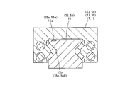
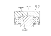
- the X-axis feed portion 10 is movably engaged with a pair of guide rails 15 and 16 arranged in parallel along the X-axis on the bed 2 and the guide rails 15 along the guide rails 2.
- the scales 15a and 15b and the reading heads 18 and 20 form a set of rear encoders, and similarly, the scales 16a and 16b and the reading heads 22 and 24 form a set of rear encoders.
- a magnetic type or an optical type can be adopted as this linear encoder, but in this example, a magnetic type is adopted.
- the reading heads 18 and 20 detect the positions of the sliders 17 and 19 in the X-axis direction and the displacements in the Y-axis and Z-axis directions by reading the scales 15a and 15b, and similarly, the reading heads 22. , 24 detect the position of the sliders 21 and 23 in the X-axis direction and the displacement in the Y-axis and Z-axis directions by reading the scales 16a and 16b.
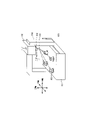
- the X-axis drive mechanism 11 is screwed into the X-axis feed motor 12, which is a servo motor, the ball screw 13 driven by the X-axis feed motor 12, and the ball screw 13, and is fixed to the lower surface of the column 3. It is composed of a ball nut (not shown), a bearing 14 that rotatably supports both ends of the ball screw 13 (the other bearing is not shown), and the like.
- the X-axis drive mechanism 11 drives the X-axis feed motor 12 to rotate the ball screw 13, so that the column 3 is guided by the guide rails 15 and 16 and moves along the X-axis.
- the Y-axis feed portion 30 engages with a pair of guide rails 35, 36 arranged in parallel along the Y-axis on the front surface of the column 3 and movably along the guide rails 35.
- the scale 36b is composed of read heads 42 and 44 fixed to the sliders 41 and 43, a Y-axis drive mechanism 31 for driving the column 3, and the like.
- the scales 35a and 35b and the reading heads 38 and 40 form a set of rear encoders, and similarly, the scales 36a and 36b and the reading heads 42 and 44 form a set of rear encoders.
- This linear encoder can also adopt a magnetic type or an optical type, but in this example, a magnetic type is adopted.
- each of the reading heads 38 and 40 detects the position of the sliders 37 and 39 in the Y-axis direction and the displacement in the Z-axis and X-axis directions by reading the scales 35a and 35b, and similarly, the reading head 42. , 44 detect the positions of the sliders 41 and 43 in the Y-axis direction and the displacements in the Z-axis and X-axis directions by reading the scales 36a and 36b.
- the Y-axis drive mechanism 31 is screwed into a Y-axis feed motor 32 which is a servo motor, a ball screw 33 driven by the Y-axis feed motor 32, and the ball screw 33, and is fixed to the rear surface of the saddle 4. It is composed of a ball nut (not shown), a bearing 34 that rotatably supports both ends of the ball screw 33 (the other bearing is not shown), and the like.
- the Y-axis drive mechanism 31 drives the Y-axis feed motor 32 to rotate the ball screw 33, so that the saddle 4 is guided by the guide rails 35 and 36 and moves along the Y-axis.
- the Z-axis feed portion 50 engages with a pair of guide rails 55, 56 arranged in parallel along the Z-axis on the bed 2 and the guide rails 55 so as to be movable along the guide rails 55.
- Two sliders 61 and 63 that are movably engaged with the guide rail 56 along the guide rail 56, a scale 56a fixed to the upper surface of the guide rail 56 along the guide rail 56, and a scale fixed to the side surface thereof. It is composed of 56b, read heads 62 and 64 fixed to the sliders 61 and 63, respectively, and a Z-axis drive mechanism 51 for driving the table 6.
- the scales 55a, 55b and the reading heads 58, 60 form a set of rear encoders, and similarly, the scales 56a, 56b and the reading heads 62, 64 form a set of rear encoders.
- This linear encoder can also adopt a magnetic type or an optical type, but in this example, a magnetic type is adopted.
- each of the reading heads 58 and 60 detects the position of the sliders 57 and 59 in the Z-axis direction and the displacement in the Y-axis and X-axis directions by reading the scales 55a and 55b, and similarly, the reading head 62. , 64 detect the position of the sliders 61 and 63 in the Z-axis direction and the displacement in the Y-axis and X-axis directions by reading the scales 56a and 56b.
- the Z-axis drive mechanism 51 is screwed into a Z-axis feed motor 52 which is a servo motor, a ball screw 53 driven by the X-axis feed motor 52, and the ball screw 3, and is fixed to the lower surface of the table 6. It is composed of a ball nut (not shown), a bearing 54 that rotatably supports both ends of the ball screw 53 (the other bearing is not shown), and the like.
- the Z-axis drive mechanism 51 drives the Z-axis feed motor 52 to rotate the ball screw 53, so that the table 6 is guided by the guide rails 55 and 56 and moves along the Z-axis.
- the motion error calculation unit 70 and the control device 75 are composed of a computer including a CPU, RAM, ROM, and the like.
- the control device 75 is a known control device that numerically controls the operation of the spindle motor (not shown), the X-axis feed motor 12, the Y-axis feed motor 32, the Z-axis feed motor 52, and the like. Further, the control device 75 drives the X-axis feed motor 12, the Y-axis feed motor 32, and the Z-axis feed motor 52, respectively, according to an operation program for motion error measurement prepared in advance, and drives the column 3, the saddle 4, and the table. 6 is moved at predetermined intervals and controlled to be positioned in each feed axis direction.
- the motion error calculation unit 70 moves the column 3, the saddle 4, and the table 6 at predetermined intervals according to the motion error measurement operation program in the respective feed axis directions.
- the data detected by the read heads 18, 20, 22, 24 of the X-axis feed unit 10 and the data detected by the read heads 38, 40, 42, 44 of the Y-axis feed unit 30 are detected.
- the motion error in the X-axis feed section 10, the Y-axis feed section 30, and the Z-axis feed section 50 is calculated based on the data and the data detected by the read heads 58, 60, 62, 64 of the Z-axis feed section 50. , Perform the calculation process as follows.
- the motion error calculation unit 70 calculates each motion error in the X-axis feed unit 10 as follows, for example.
- EXX a straight positioning error in the X-axis direction of the X-axis feed unit 10.
- EXX the average value of the difference between the movement command value in the X-axis direction and the movement value in the X-axis direction detected by the reading heads 18, 20, 22, and 24 is calculated.
- EYX which is a straightness error (Y-axis direction) in the X-axis-Y-axis plane of the X-axis feed unit 10.
- EYX any one of the displacement amounts in the Y-axis direction detected by each of the reading heads 18, 20, 22, and 24, or the average value thereof is calculated.
- E ZX which is a straightness error (Z-axis direction) in the X-axis-Z-axis plane of the X-axis feed unit 10.
- EAX any one of the displacement amounts in the Z-axis direction detected by each read head 18, 20, 22, 24, or the average value thereof is calculated.
- EAX which is an angle error around the X axis in the X axis feed unit 10.
- the difference value of the displacement in the Y-axis direction detected by the read heads 18 and 22 or the read heads 20 and 24 is calculated.
- EBX which is an angle error around the Y axis in the X axis feed unit 10.
- E CX which is an angle error around the Z axis in the X axis feed unit 10.
- the motion error calculation unit 70 calculates each motion error in the Y-axis feed unit 30 as follows, for example.
- EYY which is a straight positioning error in the Y-axis direction of the Y-axis feed unit 30.
- EXY a straightness error (in the X-axis direction) in the Y-axis-X-axis plane of the Y-axis feed unit 30.
- EXY any one of the displacement amounts in the X-axis direction detected by each read head 38, 40, 42, 44, or the average value thereof is calculated.
- E ZZ which is a straightness error (Z-axis direction) in the Y-axis-Z-axis plane of the Y-axis feed unit 30:
- E ZY any one of the displacement amounts in the Z-axis direction detected by each read head 38, 40, 42, 44, or the average value thereof is calculated.
- E AY which is an angle error around the X axis in the Y axis feed unit 30.
- E AY the difference value of the displacement in the Z-axis direction detected by the read heads 38 and 40 or the read heads 42 and 44 is calculated.
- E BY which is an angle error around the Y axis in the Y axis feed unit 30.
- ECY which is an angle error around the Z axis in the Y axis feed unit 30.
- the difference value of the position in the Y-axis direction detected by the read heads 38 and 42, or the read heads 40 and 44, or the X-axis detected by the read heads 38 and 40, or the read heads 42 and 44. Calculate the difference value of the displacement in the direction.
- the motion error calculation unit 70 calculates each motion error in the Z-axis feed unit 50, for example, as follows.
- EZZ which is a straight positioning error in the Z-axis direction of the Z-axis feed unit 50:
- the error EZZ the average value of the difference between the movement command value in the Z-axis direction and the movement value in the Z-axis direction detected by each read head 58, 60, 62, 64 is calculated.
- EXZ Straightness error (X-axis direction) in the Z-axis-X-axis plane of the Z-axis feed unit 50: As the error EXZ , any one of the displacement amounts in the X-axis direction detected by each read head 58, 60, 62, 64, or the average value thereof is calculated.
- EYZ which is a straightness error (Y-axis direction) in the Z-axis-Y-axis plane of the Z-axis feed unit 50: As the error EYZ , any one of the displacement amounts in the Y-axis direction detected by each read head 58, 60, 62, 64, or the average value thereof is calculated.
- EAZ which is an angle error around the X axis in the Z axis feed unit 50: As the error EAZ , the difference value of the displacement in the Y-axis direction detected by the read heads 58 and 60 or the read heads 62 and 64 is calculated.
- E BZ which is an angle error around the Y axis in the Z axis feed unit 30: As the error E BZ , the difference value of the position in the Z-axis direction detected by the read heads 58 and 62, or the read heads 60 and 64, or the X-axis detected by the read heads 58 and 60, or the read heads 62 and 64. Calculate the difference value of the displacement in the direction.
- E CZ Angle error around the Z axis in the Z axis feed section 50: As the error ECZ , the difference value of the displacement in the Y-axis direction detected by the read heads 58 and 62 or the read heads 60 and 64 is calculated.
- the output unit 71 is composed of a display device such as a touch panel, and displays each motion error in the X-axis feed unit 10, the Y-axis feed unit 30, and the Z-axis feed unit 50 calculated by the motion error calculation unit 70. do.
- the X-axis drive mechanism 11, the Y-axis drive mechanism 31, the Z-axis drive mechanism 51, and the spindle motor are controlled by the control device 75. Is appropriately driven to move the spindle 5 and the table 6 appropriately in a three-dimensional space, and such relative movement causes the work placed on the table 6 to be mounted on the spindle 5. It is machined by the tools that have been made.
- an operation program for measuring the motion error prepared in advance is executed under the control of the control device 75, and the X-axis feed motor 12, the Y-axis feed motor 32, and the Z-axis feed motor 52 execute the operation program.
- the column 3, the saddle 4, and the table 6 are positioned in the respective feed axis directions at predetermined intervals.
- the existing scales 55a, 55b, 56a, 56b and the reading heads 58, 60, 62, 64 arranged in the X-axis feed section 10 the Y-axis feed section 30, and the Z-axis feed section 50, each movement is performed.
- the error can be measured, without any special cost, and without complicated and troublesome preparatory work for the measurement, the X-axis feed section 10, the Y-axis feed section 30, and the Z-axis feed section.
- the motion error for 50 can be measured with high accuracy.
- the motion error (motion performance) of the X-axis feed section 10 the Y-axis feed section 30 and the Z-axis feed section 50 can be easily detected, the operation performance of the machine tool 1 that changes with time can be determined. It is possible to evaluate at a convenient time without significantly reducing the operating rate of the machine tool 1, and necessary measures such as performing necessary maintenance on the machine tool 1 based on the obtained evaluation results are taken in advance. Can be done.
- the horizontal machining center is exemplified as the machine tool 1, but the present invention is not limited to this, and the present invention includes all conventionally known machining centers such as vertical machining centers, horizontal lathes, and vertical lathes. Can be applied to machine tools.
- the motion error calculation unit 70 calculates the motion errors of the three feed units of the X-axis feed unit 10, the Y-axis feed unit 30, and the Z-axis feed unit 50.
- the motion error calculation unit 70 calculates the motion error of this one feed unit. If the machine tool is provided with two feed portions or four or more feed portions, the motion error calculation unit 70 calculates the motion error of these feed portions. It may be configured.
- the reading heads 18, 20, 22, and 24 provided on the X-axis feed unit 10 are configured to detect the position in the X-axis direction and the displacement in the Y-axis and Z-axis directions. , Not limited to this.
- one of the two reading heads provided for at least one guide rail is orthogonal to the position in the first axis direction, which is the feed direction, and the first axis in the plane including the two guide rails.
- the other reading head is configured to detect the position in the first axis direction and the position in the third axis direction orthogonal to the first axis and the second axis.
- the two reading heads provided with respect to the other guide rail may be configured to detect the position in the first axial direction and the position in the third axial direction.
- one of the two reading heads provided for at least one guide rail is orthogonal to the position in the first axis direction, which is the feed direction, and the first axis in the plane including the two guide rails. It is configured to detect a position in the second axis direction, and the other read head is configured to detect a position in the first axis direction and a position in the third axis direction orthogonal to the first axis and the second axis.
- the two reading heads provided with respect to the other guide rail may be configured to detect a position in the first axial direction and a position in the third axial direction.
- the motion error calculation unit 70 is configured to calculate six motion errors for each feed unit, but is not limited to such a configuration.
- the motion error calculation unit 70 has a positioning error (straightness positioning accuracy) in the first axis direction, a straightness error (straightness) in the second axis direction in the first axis-second axis plane, and the first.
- each guide rail with a scale for detecting the position in the biaxial direction, and only the scale necessary for calculating the error is provided for each guide rail or one of the guides. It may be provided on the rail.
- the reading head provided on the slider only the reading head necessary for calculating the error may be arranged.
Landscapes
- Engineering & Computer Science (AREA)
- Mechanical Engineering (AREA)
- Human Computer Interaction (AREA)
- Manufacturing & Machinery (AREA)
- Physics & Mathematics (AREA)
- General Physics & Mathematics (AREA)
- Automation & Control Theory (AREA)
- Machine Tool Sensing Apparatuses (AREA)
Abstract
Description
所定の送り方向に沿って平行に設けられた2本のガイドレールと、
前記各ガイドレールに対してそれぞれ少なくとも2つずつ設けられ、前記送り方向に沿って移動自在に前記各ガイドレールに係合した少なくとも4つのスライダと、
前記各スライダが取り付けられ、前記送り方向に移動する移動台と、
前記移動台を前記送り方向に移動させる駆動機構とを備えた送り装置において、
少なくとも一方の前記ガイドレールに、その前記送り方向に沿って配設されたスケールと、
前記少なくとも4つのスライダから選択される少なくとも2つのスライダであって、前記スケールが設けられたガイドレールに係合するスライダにそれぞれ設けられ、前記スケールに付与された情報を読み取って、前記送り方向における位置及び前記送り方向と直交する方向の位置を検出する読み取りヘッドと、
前記各読み取りヘッドにより検出された2方向の位置情報に基づいて、前記移動台の運動誤差を算出する運動誤差算出部とを設けて構成した送り装置に係る。
前記運動誤差算出部は、前記4つの読み取りヘッドによりそれぞれ検出された2方向の位置情報に基づいて、前記移動台の運動誤差を算出するように構成された態様(第2の態様)を採ることができる。
他方の前記ガイドレールに対して設けられる2つの読み取りヘッドは、前記第1軸方向における位置と、前記第3軸方向の位置を検出するように構成された態様(第4の態様)を採ることができる。
前記X軸送り部10は、ベッド2上に、X軸に沿って平行に配設された一対のガイドレール15,16と、このガイドレール15に、これに沿って移動自在に係合する2つのスライダ17,19と、ガイドレール15に沿ってその上面に固設されたスケール15a、及び側面に固設されたスケール15bと、前記スライダ17,19にそれぞれ固設された読み取りヘッド18,20と、前記ガイドレール16に、これに沿って移動自在に係合する2つのスライダ21,23と、ガイドレール16に沿ってその上面に固設されたスケール16a、及び側面に固設されたスケール16bと、前記スライダ21,23にそれぞれ固設された読み取りヘッド22,24と、前記コラム3を駆動するX軸駆動機構11などから構成される。
前記Y軸送り部30は、前記コラム3の前面に、Y軸に沿って平行に配設された一対のガイドレール35,36と、このガイドレール35に、これに沿って移動自在に係合する2つのスライダ37,39と、ガイドレール35に沿ってその上面に固設されたスケール35a、及び側面に固設されたスケール35bと、前記スライダ37,39にそれぞれ固設された読み取りヘッド38,40と、前記ガイドレール36に、これに沿って移動自在に係合する2つのスライダ41,43と、ガイドレール36に沿ってその上面に固設されたスケール36a、及び側面に固設されたスケール36bと、前記スライダ41,43にそれぞれ固設された読み取りヘッド42,44と、前記コラム3を駆動するY軸駆動機構31などから構成される。
前記Z軸送り部50は、ベッド2上に、Z軸に沿って平行に配設された一対のガイドレール55,56と、このガイドレール55に、これに沿って移動自在に係合する2つのスライダ57,59と、ガイドレール56に沿ってその上面に固設されたスケール55a、及び側面に固設されたスケール55bと、前記スライダ57,59にそれぞれ固設された読み取りヘッド58,60と、前記ガイドレール56に、これに沿って移動自在に係合する2つのスライダ61,63と、ガイドレール56に沿ってその上面に固設されたスケール56a、及び側面に固設されたスケール56bと、前記スライダ61,63にそれぞれ固設された読み取りヘッド62,64と、前記テーブル6を駆動するZ軸駆動機構51などから構成される。
前記制御装置75は、前記主軸モータ(図示せず)、X軸送りモータ12、Y軸送りモータ32及びZ軸送りモータ52などの動作を数値制御する公知の制御装置である。また、制御装置75は、予め用意された運動誤差測定用の動作プログラムに従って、X軸送りモータ12、Y軸送りモータ32及びZ軸送りモータ52をそれぞれ駆動して、コラム3、サドル4及びテーブル6を所定間隔で移動させ、それぞれの送り軸方向に位置決めする制御を行う。
前記運動誤差算出部70は、前記制御装置75による制御の下、前記運動誤差測定用の動作プログラムに従い、コラム3、サドル4及びテーブル6を所定間隔で移動させることによって、それぞれの送り軸方向に位置決めする動作が実行されたとき、前記X軸送り部10の読み取りヘッド18,20,22,24によって検出されるデータ、前記Y軸送り部30の読み取りヘッド38,40,42,44によって検出されるデータ、及び前記Z軸送り部50の読み取りヘッド58,60,62,64によって検出されるデータに基づいて、X軸送り部10、Y軸送り部30及びZ軸送り部50における運動誤差を、以下のようにして算出する処理を行う。
前記運動誤差算出部70は、例えば、以下のようにして、X軸送り部10における各運動誤差を算出する。
・X軸送り部10のX軸方向における真直位置決め誤差であるEXX:
誤差EXXとして、X軸方向の移動指令値と各読み取りヘッド18,20,22,24によって検出されたX軸方向の移動値との差分の平均値を算出する。
・X軸送り部10のX軸-Y軸平面における真直誤差(Y軸方向)であるEYX:
誤差EYXとして、各読み取りヘッド18,20,22,24によって検出されるY軸方向の変位量のいずれか、若しくはその平均値を算出する。
・X軸送り部10のX軸-Z軸平面における真直誤差(Z軸方向)であるEZX:
誤差EZXとして、各読み取りヘッド18,20,22,24によって検出されるZ軸方向の変位量のいずれか、若しくはその平均値を算出する。
・X軸送り部10におけるX軸まわりの角度誤差であるEAX:
誤差EAXとして、読み取りヘッド18及び22、又は読み取りヘッド20及び24によって検出されるY軸方向の変位の差分値を算出する。
・X軸送り部10におけるY軸まわりの角度誤差であるEBX:
誤差EBXとして、読み取りヘッド18及び22、若しくは読み取りヘッド20及び24によって検出されるX軸方向の位置の差分値、又は、読み取りヘッド18及び20、若しくは読み取りヘッド22及び24によって検出されるZ軸方向の変位の差分値を算出する。
・X軸送り部10におけるZ軸まわりの角度誤差であるECX:
誤差ECXとして、読み取りヘッド18及び20、又は読み取りヘッド22及び24によって検出されるY軸方向の変位の差分値を算出する。
運動誤差算出部70は、例えば、以下のようにして、Y軸送り部30における各運動誤差を算出する。
・Y軸送り部30のY軸方向における真直位置決め誤差であるEYY:
誤差EYYとして、Y軸方向の移動指令値と各読み取りヘッド38,40,42,44によって検出されたY軸方向の移動値との差分の平均値を算出する。
・Y軸送り部30のY軸-X軸平面における真直誤差(X軸方向)であるEXY:
誤差EXYとして、各読み取りヘッド38,40,42,44によって検出されるX軸方向の変位量のいずれか、若しくはその平均値を算出する。
・Y軸送り部30のY軸-Z軸平面における真直誤差(Z軸方向)であるEZY:
誤差EZYとして、各読み取りヘッド38,40,42,44によって検出されるZ軸方向の変位量のいずれか、若しくはその平均値を算出する。
・Y軸送り部30におけるX軸まわりの角度誤差であるEAY:
誤差EAYとして、読み取りヘッド38及び40、又は読み取りヘッド42及び44によって検出されるZ軸方向の変位の差分値を算出する。
・Y軸送り部30におけるY軸まわりの角度誤差であるEBY:
誤差EBYとして、読み取りヘッド38及び42、又は読み取りヘッド40及び44によって検出されるZ軸方向の変位の差分値を算出する。
・Y軸送り部30におけるZ軸まわりの角度誤差であるECY:
誤差ECYとして、読み取りヘッド38及び42、若しくは読み取りヘッド40及び44によって検出されるY軸方向の位置の差分値、又は、読み取りヘッド38及び40、若しくは読み取りヘッド42及び44によって検出されるX軸方向の変位の差分値を算出する。
運動誤差算出部70は、例えば、以下のようにして、Z軸送り部50における各運動誤差を算出する。
・Z軸送り部50のZ軸方向における真直位置決め誤差であるEZZ:
誤差EZZとして、Z軸方向の移動指令値と各読み取りヘッド58,60,62,64によって検出されたZ軸方向の移動値との差分の平均値を算出する。
・Z軸送り部50のZ軸-X軸平面における真直誤差(X軸方向)であるEXZ:
誤差EXZとして、各読み取りヘッド58,60,62,64によって検出されるX軸方向の変位量のいずれか、若しくはその平均値を算出する。
・Z軸送り部50のZ軸-Y軸平面における真直誤差(Y軸方向)であるEYZ:
誤差EYZとして、各読み取りヘッド58,60,62,64によって検出されるY軸方向の変位量のいずれか、若しくはその平均値を算出する。
・Z軸送り部50におけるX軸まわりの角度誤差であるEAZ:
誤差EAZとして、読み取りヘッド58及び60、又は読み取りヘッド62及び64によって検出されるY軸方向の変位の差分値を算出する。
・Z軸送り部30におけるY軸まわりの角度誤差であるEBZ:
誤差EBZとして、読み取りヘッド58及び62、若しくは読み取りヘッド60及び64によって検出されるZ軸方向の位置の差分値、又は、読み取りヘッド58及び60、若しくは読み取りヘッド62及び64によって検出されるX軸方向の変位の差分値を算出する。
・Z軸送り部50におけるZ軸まわりの角度誤差であるECZ:
誤差ECZとして、読み取りヘッド58及び62、又は読み取りヘッド60及び64によって検出されるY軸方向の変位の差分値を算出する。
前記出力部71は、例えば、タッチパネルなどの表示装置から構成され、前記運動誤差算出部70によって算出されたX軸送り部10、Y軸送り部30及びZ軸送り部50における各運動誤差を表示する。
2 ベッド
3 コラム
4 サドル
6 テーブル
10 X軸送り部
11 X軸駆動機構
15,16 ガイドレール
17,19,21,23 スライダ
18,20,22,24 読み取りヘッド
30 Y軸送り部
31 Y軸駆動機構
35,36 ガイドレール
37,39,41,43 スライダ
38,40,42,44 読み取りヘッド
50 Z軸送り部
51 Z軸駆動機構
55,56 ガイドレール
57,59,61,63 スライダ
58,60,62,64 読み取りヘッド
70 運動誤差算出部
71 出力部
75 制御装置
Claims (6)
- 所定の送り方向に沿って平行に設けられた2本のガイドレールと、
前記各ガイドレールに対してそれぞれ少なくとも2つずつ設けられ、前記送り方向に沿って移動自在に前記各ガイドレールに係合した少なくとも4つのスライダと、
前記各スライダが取り付けられ、前記送り方向に移動する移動台と、
前記移動台を前記送り方向に移動させる駆動機構とを備えた送り装置において、
少なくとも一方の前記ガイドレールに、その前記送り方向に沿って配設されたスケールと、
前記少なくとも4つのスライダから選択される少なくとも2つのスライダであって、前記スケールが設けられたガイドレールに係合するスライダにそれぞれ設けられ、前記スケールに付与された情報を読み取って、前記送り方向における位置及び前記送り方向と直交する方向の位置を検出する読み取りヘッドと、
前記各読み取りヘッドにより検出された2方向の位置情報に基づいて、前記移動台の運動誤差を算出する運動誤差算出部とを設けて構成したことを特徴とする送り装置。 - 前記スケールを前記2本のガイドレールに配設するともに、前記読み取りヘッドを前記4つのスライダにそれぞれ配設し、
前記運動誤差算出部は、前記4つの読み取りヘッドによりそれぞれ検出された2方向の位置情報に基づいて、前記移動台の運動誤差を算出するように構成されていることを特徴とする請求項1記載の送り装置。 - 少なくとも一方の前記ガイドレールに対して設けられる2つの読み取りヘッドは、前記送り方向である第1軸方向における位置と、前記2本のガイドレールを含む平面内において前記第1軸と直交する第2軸方向の位置を検出するように構成され、他方のガイドレールに対して設けられる2つの読み取りヘッドは、前記第1軸方向における位置と、前記第1軸及び第2軸と直交する第3軸方向の位置を検出するように構成されていることを特徴とする請求項2記載の送り装置。
- 少なくとも一方の前記ガイドレールに対して設けられる2つの読み取りヘッドの内の一方は、前記送り方向である第1軸方向における位置と、前記2本のガイドレールを含む平面内において前記第1軸と直交する第2軸方向の位置を検出するように構成されるとともに、他方の読み取りヘッドは前記第1軸方向における位置と、前記第1軸及び第2軸と直交する第3軸方向の位置を検出するように構成され、
他方の前記ガイドレールに対して設けられる2つの読み取りヘッドは、前記第1軸方向における位置と、前記第3軸方向の位置を検出するように構成されていることを特徴とする請求項2記載の送り装置。 - 前記運動誤差算出部は、前記第1軸方向における位置決め誤差と、前記第1軸-第2軸平面における前記第2軸方向の真直誤差、前記第1軸-第3軸平面における前記第3軸方向の真直誤差、前記第1軸まわりの角度誤差、前記第2軸まわりの角度誤差及び第3軸まわりの角度誤差の中から選択される少なくとも1つの誤差とを算出するように構成されていることを特徴とする請求項3又は4記載の送り装置。
- 前記請求項1乃至5記載のいずれかの送り装置を備えていることを特徴とする工作機械。
Priority Applications (5)
| Application Number | Priority Date | Filing Date | Title |
|---|---|---|---|
| PCT/JP2020/045967 WO2022123711A1 (ja) | 2020-12-10 | 2020-12-10 | 送り装置 |
| EP20965094.4A EP4249168A4 (en) | 2020-12-10 | 2020-12-10 | FEEDING DEVICE |
| CN202080106535.0A CN116367959A (zh) | 2020-12-10 | 2020-12-10 | 进给装置 |
| JP2021560023A JP7448895B2 (ja) | 2020-12-10 | 2020-12-10 | 送り装置 |
| US18/038,929 US20240017365A1 (en) | 2020-12-10 | 2020-12-10 | Feed apparatus |
Applications Claiming Priority (1)
| Application Number | Priority Date | Filing Date | Title |
|---|---|---|---|
| PCT/JP2020/045967 WO2022123711A1 (ja) | 2020-12-10 | 2020-12-10 | 送り装置 |
Publications (1)
| Publication Number | Publication Date |
|---|---|
| WO2022123711A1 true WO2022123711A1 (ja) | 2022-06-16 |
Family
ID=81973443
Family Applications (1)
| Application Number | Title | Priority Date | Filing Date |
|---|---|---|---|
| PCT/JP2020/045967 WO2022123711A1 (ja) | 2020-12-10 | 2020-12-10 | 送り装置 |
Country Status (5)
| Country | Link |
|---|---|
| US (1) | US20240017365A1 (ja) |
| EP (1) | EP4249168A4 (ja) |
| JP (1) | JP7448895B2 (ja) |
| CN (1) | CN116367959A (ja) |
| WO (1) | WO2022123711A1 (ja) |
Citations (10)
| Publication number | Priority date | Publication date | Assignee | Title |
|---|---|---|---|---|
| WO2005111754A1 (ja) * | 2004-05-19 | 2005-11-24 | Sumitomo Heavy Industries, Ltd. | 移動体位置制御装置及びこの制御装置を用いたステージ装置 |
| JP2007331086A (ja) * | 2006-06-19 | 2007-12-27 | Sumitomo Heavy Ind Ltd | ステージ装置 |
| WO2009069423A1 (ja) * | 2007-11-30 | 2009-06-04 | Kabushiki Kaisha Yaskawa Denki | スライドステージおよびxy方向可動スライドステージ |
| JP2012045703A (ja) * | 2010-07-26 | 2012-03-08 | Mori Seiki Co Ltd | 工作機械 |
| JP2012518167A (ja) * | 2009-02-16 | 2012-08-09 | レニショウ パブリック リミテッド カンパニー | エンコーダスケール部材および取付方法 |
| US20140204392A1 (en) * | 2013-01-23 | 2014-07-24 | Samsung Display Co., Ltd. | Stage transferring device and position measuring method thereof |
| CN104439570A (zh) * | 2014-11-28 | 2015-03-25 | 广东工业大学 | 一种高速大行程双牛头背斜床身电火花机床 |
| JP2015166114A (ja) * | 2014-03-03 | 2015-09-24 | 日本精工株式会社 | テーブル装置、測定装置、及び工作機械 |
| JP2018120359A (ja) * | 2017-01-24 | 2018-08-02 | Thk株式会社 | 加工制御システム、及び運動案内装置 |
| JP2019206043A (ja) | 2018-05-28 | 2019-12-05 | Dmg森精機株式会社 | 送り装置の運動誤差同定方法 |
Family Cites Families (2)
| Publication number | Priority date | Publication date | Assignee | Title |
|---|---|---|---|---|
| JP5172265B2 (ja) * | 2007-10-02 | 2013-03-27 | 東芝機械株式会社 | 駆動装置、これを用いた加工機械および測定機械 |
| TWI666421B (zh) * | 2018-07-10 | 2019-07-21 | 英屬維京群島商詮優科技有限公司 | 自動化設備之位移量測機構 |
-
2020
- 2020-12-10 EP EP20965094.4A patent/EP4249168A4/en active Pending
- 2020-12-10 JP JP2021560023A patent/JP7448895B2/ja active Active
- 2020-12-10 WO PCT/JP2020/045967 patent/WO2022123711A1/ja active Application Filing
- 2020-12-10 US US18/038,929 patent/US20240017365A1/en active Pending
- 2020-12-10 CN CN202080106535.0A patent/CN116367959A/zh active Pending
Patent Citations (10)
| Publication number | Priority date | Publication date | Assignee | Title |
|---|---|---|---|---|
| WO2005111754A1 (ja) * | 2004-05-19 | 2005-11-24 | Sumitomo Heavy Industries, Ltd. | 移動体位置制御装置及びこの制御装置を用いたステージ装置 |
| JP2007331086A (ja) * | 2006-06-19 | 2007-12-27 | Sumitomo Heavy Ind Ltd | ステージ装置 |
| WO2009069423A1 (ja) * | 2007-11-30 | 2009-06-04 | Kabushiki Kaisha Yaskawa Denki | スライドステージおよびxy方向可動スライドステージ |
| JP2012518167A (ja) * | 2009-02-16 | 2012-08-09 | レニショウ パブリック リミテッド カンパニー | エンコーダスケール部材および取付方法 |
| JP2012045703A (ja) * | 2010-07-26 | 2012-03-08 | Mori Seiki Co Ltd | 工作機械 |
| US20140204392A1 (en) * | 2013-01-23 | 2014-07-24 | Samsung Display Co., Ltd. | Stage transferring device and position measuring method thereof |
| JP2015166114A (ja) * | 2014-03-03 | 2015-09-24 | 日本精工株式会社 | テーブル装置、測定装置、及び工作機械 |
| CN104439570A (zh) * | 2014-11-28 | 2015-03-25 | 广东工业大学 | 一种高速大行程双牛头背斜床身电火花机床 |
| JP2018120359A (ja) * | 2017-01-24 | 2018-08-02 | Thk株式会社 | 加工制御システム、及び運動案内装置 |
| JP2019206043A (ja) | 2018-05-28 | 2019-12-05 | Dmg森精機株式会社 | 送り装置の運動誤差同定方法 |
Non-Patent Citations (1)
| Title |
|---|
| See also references of EP4249168A4 |
Also Published As
| Publication number | Publication date |
|---|---|
| US20240017365A1 (en) | 2024-01-18 |
| JP7448895B2 (ja) | 2024-03-13 |
| EP4249168A4 (en) | 2024-08-07 |
| CN116367959A (zh) | 2023-06-30 |
| EP4249168A1 (en) | 2023-09-27 |
| JPWO2022123711A1 (ja) | 2022-06-16 |
Similar Documents
| Publication | Publication Date | Title |
|---|---|---|
| US10209107B2 (en) | Geometric error identification method of multi-axis machine tool and multi-axis machine tool | |
| US4587622A (en) | Method and apparatus for determining and correcting guidance errors | |
| US5357450A (en) | Automated maintenance system for computer numerically controlled machines | |
| JP5235284B2 (ja) | 測定方法及び工作機械 | |
| WO2002032620A1 (fr) | Dispositif et procede de mesure, machine-outil dotee dudit dispositif, et procede de traitement de piece | |
| GB2052746A (en) | Method and a testing instrument for testing the tooth flank profiles of large diameter toothed wheels | |
| JP5388823B2 (ja) | 軌跡測定装置 | |
| CN102636137A (zh) | 关节臂式坐标测量机中revo测头位置姿态标定方法 | |
| TW202035083A (zh) | 校正軸運動的方法 | |
| US20180246492A1 (en) | Numerical Control Device | |
| US20060282179A1 (en) | Positioning system for eliminating lost motion effect | |
| Iwasawa et al. | Development of a measuring method for several types of programmed tool paths for NC machine tools using a laser displacement interferometer and a rotary encoder | |
| EP1434027A2 (en) | Apparatus for measuring angular position and displacement of a rotary table and accuracy analyzing apparatus therefor | |
| JP4799472B2 (ja) | 工具の刃先位置の測定方法及び装置、ワークの加工方法並びに工作機械 | |
| JP5297749B2 (ja) | 自動寸法測定装置 | |
| CN110411347B (zh) | 数控机床工作台瞬时旋转中心的检测装置及其检测方法 | |
| WO2022123711A1 (ja) | 送り装置 | |
| CN117760298A (zh) | 主轴箱平行度的检测装置及其检测方法 | |
| US3698817A (en) | Method and apparatus for manufacturing reference scales | |
| JP2002107142A (ja) | 歯車測定機 | |
| JP2755346B2 (ja) | 自動工作機械の運動精度測定方法及びその装置 | |
| JP2006323773A (ja) | 駆動制御用補正データの取得方法 | |
| JP6960376B2 (ja) | 送り装置の運動誤差同定方法 | |
| US20120243956A1 (en) | Machine tool | |
| JPH08278103A (ja) | ワーク端面の平面度測定方法および装置 |
Legal Events
| Date | Code | Title | Description |
|---|---|---|---|
| ENP | Entry into the national phase |
Ref document number: 2021560023 Country of ref document: JP Kind code of ref document: A |
|
| 121 | Ep: the epo has been informed by wipo that ep was designated in this application |
Ref document number: 20965094 Country of ref document: EP Kind code of ref document: A1 |
|
| WWE | Wipo information: entry into national phase |
Ref document number: 18038929 Country of ref document: US |
|
| WWE | Wipo information: entry into national phase |
Ref document number: 2020965094 Country of ref document: EP |
|
| ENP | Entry into the national phase |
Ref document number: 2020965094 Country of ref document: EP Effective date: 20230622 |
|
| NENP | Non-entry into the national phase |
Ref country code: DE |