WO2022113834A1 - システム、撮像装置、情報処理装置、情報処理方法および情報処理プログラム - Google Patents
システム、撮像装置、情報処理装置、情報処理方法および情報処理プログラム Download PDFInfo
- Publication number
- WO2022113834A1 WO2022113834A1 PCT/JP2021/042137 JP2021042137W WO2022113834A1 WO 2022113834 A1 WO2022113834 A1 WO 2022113834A1 JP 2021042137 W JP2021042137 W JP 2021042137W WO 2022113834 A1 WO2022113834 A1 WO 2022113834A1
- Authority
- WO
- WIPO (PCT)
- Prior art keywords
- user
- unit
- coordinate information
- image pickup
- imaging mode
- Prior art date
- Legal status (The legal status is an assumption and is not a legal conclusion. Google has not performed a legal analysis and makes no representation as to the accuracy of the status listed.)
- Ceased
Links
Images



Classifications
-
- H—ELECTRICITY
- H04—ELECTRIC COMMUNICATION TECHNIQUE
- H04N—PICTORIAL COMMUNICATION, e.g. TELEVISION
- H04N23/00—Cameras or camera modules comprising electronic image sensors; Control thereof
- H04N23/60—Control of cameras or camera modules
- H04N23/61—Control of cameras or camera modules based on recognised objects
- H04N23/611—Control of cameras or camera modules based on recognised objects where the recognised objects include parts of the human body
-
- G—PHYSICS
- G06—COMPUTING OR CALCULATING; COUNTING
- G06T—IMAGE DATA PROCESSING OR GENERATION, IN GENERAL
- G06T7/00—Image analysis
- G06T7/70—Determining position or orientation of objects or cameras
- G06T7/73—Determining position or orientation of objects or cameras using feature-based methods
-
- A—HUMAN NECESSITIES
- A63—SPORTS; GAMES; AMUSEMENTS
- A63F—CARD, BOARD, OR ROULETTE GAMES; INDOOR GAMES USING SMALL MOVING PLAYING BODIES; VIDEO GAMES; GAMES NOT OTHERWISE PROVIDED FOR
- A63F13/00—Video games, i.e. games using an electronically generated display having two or more dimensions
- A63F13/20—Input arrangements for video game devices
- A63F13/21—Input arrangements for video game devices characterised by their sensors, purposes or types
- A63F13/213—Input arrangements for video game devices characterised by their sensors, purposes or types comprising photodetecting means, e.g. cameras, photodiodes or infrared cells
-
- A—HUMAN NECESSITIES
- A63—SPORTS; GAMES; AMUSEMENTS
- A63F—CARD, BOARD, OR ROULETTE GAMES; INDOOR GAMES USING SMALL MOVING PLAYING BODIES; VIDEO GAMES; GAMES NOT OTHERWISE PROVIDED FOR
- A63F13/00—Video games, i.e. games using an electronically generated display having two or more dimensions
- A63F13/25—Output arrangements for video game devices
-
- A—HUMAN NECESSITIES
- A63—SPORTS; GAMES; AMUSEMENTS
- A63F—CARD, BOARD, OR ROULETTE GAMES; INDOOR GAMES USING SMALL MOVING PLAYING BODIES; VIDEO GAMES; GAMES NOT OTHERWISE PROVIDED FOR
- A63F13/00—Video games, i.e. games using an electronically generated display having two or more dimensions
- A63F13/40—Processing input control signals of video game devices, e.g. signals generated by the player or derived from the environment
- A63F13/42—Processing input control signals of video game devices, e.g. signals generated by the player or derived from the environment by mapping the input signals into game commands, e.g. mapping the displacement of a stylus on a touch screen to the steering angle of a virtual vehicle
- A63F13/428—Processing input control signals of video game devices, e.g. signals generated by the player or derived from the environment by mapping the input signals into game commands, e.g. mapping the displacement of a stylus on a touch screen to the steering angle of a virtual vehicle involving motion or position input signals, e.g. signals representing the rotation of an input controller or a player's arm motions sensed by accelerometers or gyroscopes
-
- G—PHYSICS
- G06—COMPUTING OR CALCULATING; COUNTING
- G06F—ELECTRIC DIGITAL DATA PROCESSING
- G06F1/00—Details not covered by groups G06F3/00 - G06F13/00 and G06F21/00
- G06F1/16—Constructional details or arrangements
- G06F1/1613—Constructional details or arrangements for portable computers
- G06F1/163—Wearable computers, e.g. on a belt
-
- G—PHYSICS
- G06—COMPUTING OR CALCULATING; COUNTING
- G06F—ELECTRIC DIGITAL DATA PROCESSING
- G06F3/00—Input arrangements for transferring data to be processed into a form capable of being handled by the computer; Output arrangements for transferring data from processing unit to output unit, e.g. interface arrangements
- G06F3/01—Input arrangements or combined input and output arrangements for interaction between user and computer
- G06F3/017—Gesture based interaction, e.g. based on a set of recognized hand gestures
-
- G—PHYSICS
- G06—COMPUTING OR CALCULATING; COUNTING
- G06F—ELECTRIC DIGITAL DATA PROCESSING
- G06F3/00—Input arrangements for transferring data to be processed into a form capable of being handled by the computer; Output arrangements for transferring data from processing unit to output unit, e.g. interface arrangements
- G06F3/01—Input arrangements or combined input and output arrangements for interaction between user and computer
- G06F3/03—Arrangements for converting the position or the displacement of a member into a coded form
- G06F3/0304—Detection arrangements using opto-electronic means
-
- H—ELECTRICITY
- H04—ELECTRIC COMMUNICATION TECHNIQUE
- H04N—PICTORIAL COMMUNICATION, e.g. TELEVISION
- H04N23/00—Cameras or camera modules comprising electronic image sensors; Control thereof
- H04N23/60—Control of cameras or camera modules
- H04N23/667—Camera operation mode switching, e.g. between still and video, sport and normal or high- and low-resolution modes
-
- G—PHYSICS
- G06—COMPUTING OR CALCULATING; COUNTING
- G06T—IMAGE DATA PROCESSING OR GENERATION, IN GENERAL
- G06T2207/00—Indexing scheme for image analysis or image enhancement
- G06T2207/10—Image acquisition modality
- G06T2207/10024—Color image
-
- G—PHYSICS
- G06—COMPUTING OR CALCULATING; COUNTING
- G06T—IMAGE DATA PROCESSING OR GENERATION, IN GENERAL
- G06T2207/00—Indexing scheme for image analysis or image enhancement
- G06T2207/20—Special algorithmic details
- G06T2207/20081—Training; Learning
-
- G—PHYSICS
- G06—COMPUTING OR CALCULATING; COUNTING
- G06T—IMAGE DATA PROCESSING OR GENERATION, IN GENERAL
- G06T2207/00—Indexing scheme for image analysis or image enhancement
- G06T2207/30—Subject of image; Context of image processing
- G06T2207/30196—Human being; Person
Definitions
- the present invention relates to a system, an image pickup device, an information processing device, an information processing method, and an information processing program.
- Patent Document 1 an operation device that is connected to an information processing device such as a computer or a game device and transmits an operation signal to the information processing device is known (see, for example, Patent Document 1).
- the controller (operation device) described in Patent Document 1 has a left side grip portion and a right side grip portion gripped by the left and right hands of the user, and a direction button and an operation button arranged on the front surface of the controller.
- an object of the present invention is to provide a system, an image pickup device, an information processing device, an information processing method, and an information processing program, which are highly convenient for the user and can perform processing accurately according to the image pickup mode. ..
- a first imaging mode comprising a first image sensor that generates a first image signal by synchronously scanning all pixels at predetermined timings, and imaging from the user's first-person perspective
- An imaging device that captures images in one of the second imaging modes that capture the user from the user's third-person perspective, recognizes the user based on the first image signal, and obtains coordinate information about the user based on the first image signal.
- the first process is performed based on the coordinate information calculated in the first imaging mode, and if it is determined to be the second imaging mode, the coordinates calculated in the second imaging mode.
- a system including a third arithmetic processing device that performs a second processing based on information is provided.
- a first imaging mode comprising a first image sensor that generates a first image signal by synchronously scanning all pixels at a predetermined timing and imaging from the user's first-person perspective.
- the image pickup unit that takes an image in any of the second image pickup modes that take an image of the user from the user's third person viewpoint, the user is recognized based on the first image signal, and the coordinate information about the user is based on the first image signal.
- An image pickup device including an arithmetic processing unit for calculating the above and an information output unit for outputting coordinate information is provided.
- a first imaging mode comprising a first image sensor that generates a first image signal by synchronously scanning all pixels at a predetermined timing and imaging from the user's first-person viewpoint.
- the user is imaged by one of the second imaging modes in which the user is imaged from the user's third person viewpoint, the user is recognized based on the first image signal, and the coordinate information about the user is calculated based on the first image signal.
- the acquisition unit that acquires the coordinate information from the image pickup device that outputs the coordinate information, and the first that determines whether the image pickup is performed in the first image pickup mode or the second image pickup mode based on the coordinate information.
- the first processing is performed based on the coordinate information calculated in the first imaging mode, and when the second imaging mode is determined, the first processing is performed.
- An information processing apparatus including a second arithmetic processing unit that performs a second process based on the coordinate information calculated in the second imaging mode is provided.
- a first imaging mode comprising a first image sensor that generates a first image signal by synchronously scanning all pixels at a predetermined timing and imaging from the user's first-person viewpoint.
- the first process is performed based on the coordinate information calculated in the first imaging mode, and if it is determined to be the second imaging mode, the second imaging mode is performed.
- An information processing method including a processing step of performing a second processing based on the coordinate information calculated in the above is provided.
- a first imaging mode comprising a first image sensor that generates a first image signal by synchronously scanning all pixels at a predetermined timing and imaging from the user's first-person viewpoint.
- the first process is performed based on the coordinate information calculated in the first imaging mode, and when it is determined to be the second imaging mode, it is calculated in the second imaging mode.
- An information processing program is provided that enables a computer to realize a function of performing a second process based on the coordinate information. According to the above configuration, the coordinate information about the user is calculated based on the image signal, and the imaging mode is determined based on the calculated coordinate information, which is highly convenient for the user and accurately corresponds to the imaging mode. Processing can be performed.
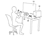
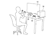
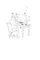
- FIG. 1A and 1B are schematic views showing the entire system 1 according to the first embodiment of the present invention
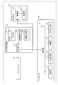
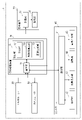
- FIG. 2 is a block diagram showing a schematic configuration of the system 1.
- the system 1 according to the present embodiment is a game system including an HMD unit 20, which is a first sensor device, an information processing device 30, a controller 40, and a display device 50.
- the information processing device 30 is connected to each of the HMD unit 20, the controller 40, and the display device 50 by a wired or wireless network.
- the information processing device 30 advances the game according to the information transmitted from the HMD unit 20 and the controller 40, and the HMD unit 20 and the display device 50 display the execution screen of the information processing device 30, for example, a game screen. Is displayed.
- the HMD unit 20 calculates the coordinate information about the user who is the player of the game and transmits it to the information processing apparatus 30.
- the coordinate information regarding the user includes at least one of the coordinate information of the feature point regarding the posture of the user, the coordinate information of the feature point regarding the shape of the user's arm, or the coordinate information of the feature point regarding the shape of the user's finger. ..
- the HMD unit 20 also functions as an operating device for accepting user operations, like the controller 40, by calculating and outputting coordinate information about the user.
- the HMD unit 20 can be used by being attached to the user's head as shown in FIG. 1A, and can also be used by being placed on a table or the like as shown in FIG. 1B. Is.
- the HMD unit 20 when the HMD unit 20 is used by being mounted on the user's head, the HMD unit 20 has a function of a display device and a function of an image pickup device that performs image pickup in the first image pickup mode for image pickup from the user's first-person viewpoint. It has and is configured to be removable from the user's head. As shown in the example of FIG.
- the HMD unit 20 is configured so that the HMD unit 20 can be attached to the user's head by the attachment portion 20A that can be attached to the user's body.
- the HMD unit 20 and the mounting portion 20A may have a band type as in the example of FIG. 1A, or may have any configuration such as a helmet type or a glasses type. Further, when mounting the HMD unit 20, for example, by displaying a tutorial or the like on the HMD unit 20 by the information processing device 30, it is preferable to guide the user to properly mount the HMD unit 20 by the mounting unit 20A.
- the HMD unit 20 when used by placing it on a table or the like as shown in FIG. 1B, the HMD unit 20 has a function of an imaging device that performs imaging in a second imaging mode in which the user is imaged from the third person viewpoint of the user. Then, the HMD unit 20 is arranged at a position where the user fits in the field of view, for example, at a distance of about 1 meter from the user in order to image the user from the user's third person viewpoint. In the example of FIG. 1B, the HMD unit 20 is arranged in the vicinity of the display device 50. The optimum placement position of the HMD unit 20 differs depending on the purpose.
- the HMD unit 20 it is desired to arrange the HMD unit 20 at a position where the object to be grasped fits in the field of view, such as the entire body, upper body, and hand of the user, depending on the content of the game to be played.
- the information processing apparatus 30 may display a tutorial or the like on the display device 50 to guide the user to arrange the HMD unit 20 at an appropriate position.
- the HMD unit 20 is mounted on the head and imaged in the first imaging mode or the HMD unit 20 is placed on a table or the like and imaged in the second imaging mode is the content of the game to be played. It depends on the purpose such as.
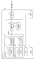
- FIG. 3 is a block diagram showing a schematic configuration of the HMD unit 20 in the system 1 according to the embodiment of the present invention.
- the HMD unit 20 includes an RGB camera 21 which is a first image pickup device, an IMU (Inertial Measurement Unit) 23, a calculation unit 24 which functions as a first arithmetic processing unit, an information output unit 25, and a reception unit 26. Including the display unit 27.
- the RGB camera 21 includes an image sensor 211 which is a first image sensor and a processing circuit 212 connected to the image sensor 211.
- the image sensor 211 generates the RGB image signal 213, which is the first image signal, by synchronously scanning all pixels (all pixels), for example, at a predetermined cycle or at a predetermined timing according to a user operation.
- the processing circuit 212 converts, for example, the RGB image signal 213 into a format suitable for storage and transmission. Further, the processing circuit 212 gives a time stamp to the RGB image signal 213.
- a signal capable of constructing an image based on the signal is referred to as an image signal. Therefore, the RGB image signal 213 shows an example of an image signal.
- the IMU 23 is an inertial sensor that detects the posture of the HMD unit 20 itself, more specifically, the image sensor 211.
- the IMU 23 acquires the three-dimensional attitude information of the image sensor 211 at a predetermined cycle or at a predetermined timing, and outputs the attitude information to the information output unit 25.
- the calculation unit 24 includes the coordinate calculation unit 241 and the trained model 242, and calculates the coordinate information about the user based on the RGB image signal 213 generated by the RGB camera 21.
- the coordinate calculation unit 241 of the calculation unit 24 recognizes the user by performing subject recognition based on, for example, the RGB image signal 213.
- the coordinate calculation unit 241 identifies each user.
- the coordinate calculation unit 241 calculates the coordinate information indicating the positions of the plurality of joints possessed by the user from the RGB image signal 213 based on the trained model 242 for each recognized user.
- the positions of the plurality of joints possessed by the user correspond to the feature points relating to the posture of the user, the feature points relating to the shape of the arm of the user, or the feature points relating to the shape of the finger of the user.
- the trained model 242 can be preliminarily constructed by performing supervised learning using, for example, an image of a person having a plurality of joints as input data and coordinate information indicating the positions of a plurality of joints of the person as correct answer data. can.
- supervised learning As for the specific method of machine learning, since various known techniques can be used, detailed description thereof will be omitted.
- the calculation unit 24 is provided with a relationship learning unit, and each time the RGB image signal 213 is input, the relationship between the image based on the input RGB image signal 213 and the coordinate information indicating the position of the joint is learned.
- the trained model 242 may be updated.
- the information output unit 25 outputs the coordinate information about the user calculated by the calculation unit 24 and the posture information acquired by the IMU 23 to the information processing device 30.
- the receiving unit 26 receives information indicating the display image generated by the information processing device 30 from the information processing device 30.
- the display unit 27 includes a display element such as an LCD (Liquid Crystal Display) or an organic EL, and an optical device such as a lens, and displays a display image to the user based on the information received by the reception unit 26. It is possible to present.
- the display element of the display unit 27 may be a transmissive type display element or a non-transparent type display element.
- a terminal device such as a smartphone that can be attached to and detached from the housing of the HMD unit 20 may be used as a display device.
- a wearable device such as an AR (Augmented Reality) glass or an MR (Mixed Reality) glass may be used as the HMD unit 20.
- the HMD unit 20 completes the process from the generation of the RGB image signal 213 to the calculation of the coordinate information about the user by itself, and calculates without outputting the RGB image signal 213 to the information processing apparatus 30.
- Information processing and attitude information can be output.
- the HMD unit 20 preferably has an independent power supply.
- the HMD unit 20 has a first image pickup mode in which the user is imaged from the first person viewpoint of the user and a second image pickup mode in which the user is imaged from the third person viewpoint of the user.
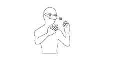
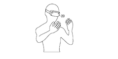
- the first imaging mode as shown in FIG. 4A, the user's hand mainly fits in the field of view, and the display device 50 may fit in the field of view behind (rearward) the hand when viewed from the user. ..
- the user's head does not fit in the field of view. For example, when the user raises both arms or poses with his / her fingers near the shoulders, those parts are covered. It doesn't fit in the image.
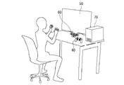
- the second imaging mode As shown in FIG. 4B, when the upper body and hand of the user mainly fit in the field of view and the user is posing with his arms or fingers, almost all of them are in the field of field. Fits in. Further, in the second imaging mode, the display device 50 does not fit in the field of view. Therefore, in the first image pickup mode and the second image pickup mode of the present embodiment, the subject included in the image data based on the generated image signal is different.
- the information processing unit 30 is implemented by a computer having, for example, a communication interface, a processor, and a memory, and a communication unit 31 and a control unit that functions as a second arithmetic processing unit and a third arithmetic processing unit.
- the control unit 32 functions as a determination unit 321, a control value calculation unit 322, and an image generation unit 323, which are realized by the processor operating according to a program stored in a memory or received via a communication interface. include.
- the functions of each part will be further described.
- the communication unit 31 receives the coordinate information about the user and the posture information output from the information output unit 25 of the HMD unit 20, and outputs a display image to be displayed on the display unit 27 of the HMD unit 20. Further, the communication unit 31 can communicate with the controller 40 and outputs a display image to be displayed on the display device 50.
- the determination unit 321 of the control unit 32 determines whether the image pickup is performed in the first image pickup mode or the second image pickup mode based on the coordinate information. For example, the determination unit 321 recognizes the coordinate information output from the HMD unit 20 based on the coordinate information of the feature points related to the posture of the user, and when the coordinate information includes the face or head of the user, the determination unit 321 recognizes the coordinate information. It can be determined that the HMD unit 20 is performing the imaging in the second imaging mode. Similarly, the determination unit 321 recognizes, for example, based on the coordinate information of the feature points related to the shape of the user's arm among the coordinate information, and the user's hand or fist is present in front of the user's arm in the coordinate information.
- Unit 321 can determine that the HMD unit 20 is performing imaging in the first imaging mode.
- the determination unit 321 is not limited to the relative positions of the arms, hands, and fists described above, and may determine the imaging mode based on the relative positions of other parts. For example, the determination unit 321 may determine the imaging mode based on the terminal portion of the user's body, more specifically, the relative positions of the legs and legs. Further, the above-mentioned determination method may be predetermined or may be set by the user. Further, the determination may be made by combining other information. For example, the posture information acquired by the IMU23 of the HMD unit 20 may be used. For example, the relative positional relationship between the user and the HMD unit 20 may be detected based on the posture information by the IMU 23, and the detected positional relationship may be used for determining the imaging mode. Further, the image pickup mode may be determined based only on the posture information acquired by the IMU 23 of the HMD unit 20.
- the display device 50 is contained in the field of view. It may be estimated and it may be determined that the HMD unit 20 is performing the imaging in the first imaging mode. Further, the HMD unit 20 may be provided with a mounting sensor for detecting the mounting state of the HMD unit 20 by the mounting unit 20A, and the determination may be made according to the mounting state detected by the mounting sensor. For example, when the attached state indicates that "the HMD unit 20 is attached to the user", it is determined that the image is being taken in the first imaging mode, and the attached state is "the HMD unit 20 is attached to the user".
- the mounting sensor can be configured by, for example, a contact sensor, a detachable sensor, a switch, or the like, depending on the configuration of the mounting portion 20A. Further, instead of or in addition to the mounting sensor, a contact sensor, an attitude sensor, or the like for detecting whether or not the HMD unit 20 is mounted on a table or the like may be provided.
- the control unit 32 displays a message such as "Please show the palms of both hands" on the display unit 27 of the HMD unit 20 and the display unit 52 of the display device 50.
- the HMD unit 20 is performing imaging in the first imaging mode, as shown in FIG. 4A, the user turns the palm toward the HMD unit 20 mounted on the head. Therefore, in the coordinate information output from the HMD unit 20, the thumbs of both hands of the user face outward.
- the HMD unit 20 is performing imaging in the second imaging mode, as shown in FIG. 4B, the user turns the palm toward the HMD unit 20 placed on a table or the like.
- the thumbs of both hands of the user face inward. In either case, a more accurate determination can be made by making a determination by combining whether the hands are facing upward or downward, whether the arms are crossed, and the like.
- poses other than the above may be adopted as long as there is a difference in the coordinate information between the first imaging mode and the second imaging mode and the poses can be identified.
- the control value calculation unit 322 calculates the control value of the feedback control to the external device including the HMD unit 20, the controller 40, and the display device 50 according to the image pickup mode determined by the determination unit 321. As described above, the HMD unit 20 and the controller 40 function as an operating device for accepting user operations. Therefore, the control value calculation unit 322 controls feedback to an external device including the HMD unit 20, the controller 40, and the display device 50 in response to a user operation performed via either the HMD unit 20 or the controller 40. Calculate the control value. The calculated control value is output to the controller 40 via the communication unit 31.
- the image generation unit 323 generates a display image showing the user's state according to the image pickup mode determined by the determination unit 321. More specifically, the image generation unit 323 generates a display image to be displayed on the display unit 27 of the HMD unit 20 and the display unit 52 of the display device 50 according to the control value calculated by the control value calculation unit 322. ..
- the generated display image is output to the HMD unit 20 and the display device 50 via the communication unit 31.
- the display image includes a so-called First Person View image that reproduces the user's viewpoint, a so-called Third Person View image that views the user from the outside, and the like. What kind of display image is used is determined according to the content of the game to be played and the purpose such as the scene. Further, the details of the calculation of the control value and the generation of the display image will be described in relation to the description of the configuration of the controller 40 and the display device 50 described later.
- the controller 40 includes a communication unit 41, an operation unit 42, a force sense presentation unit 43, a vibration unit 44, and a voice output unit 45.
- the user can perform various operations related to the game by operating the controller 40.
- the communication unit 41 receives the control value output from the communication unit 31 of the information processing device 30 and outputs it to each unit of the force sense presentation unit 43, the vibration unit 44, and the voice output unit 45. Further, the communication unit 41 outputs the information regarding the user operation received by the operation unit 42 to the information processing apparatus 30.
- the operation unit 42 includes a plurality of controls such as buttons and pads, and receives a user's operation input to the controls.
- the force sense presentation unit 43 is provided on at least a part of the operators of the operation unit 42, and presents to the user a force that opposes or interlocks with the user operation according to the control value supplied from the information processing device 30.
- the force sense presentation unit 43 can be configured by a motor, an actuator, or the like including a rotating rotor.
- As the force sense presenting device constituting the force sense presentation unit 43 a widely known one can be adopted, and therefore detailed description thereof will be omitted here.
- the vibration unit 44 generates vibration according to a control value supplied from the information processing device 30, and can be configured by, for example, a motor.
- the vibration unit 44 can notify the user that the user operation has been performed correctly and that the information processing apparatus 30 has recognized it by generating vibration when the user operation is performed.
- the voice output unit 45 outputs voice according to a control value supplied from the information processing device 30, and can be configured by, for example, a speaker. By outputting the voice when the user operation is performed, the voice output unit 45 can notify the user that the user operation is correctly performed and recognized by the information processing apparatus 30.
- the control value calculation unit 322 of the information processing apparatus 30 calculates the control value of the feedback control to the controller 40, but more specifically, according to the image pickup mode determined by the determination unit 321.
- the control value of the feedback control to the force sense presentation unit 43, the vibration unit 44, and the voice output unit 45 of the controller 40 is calculated.
- the determination unit 321 determines that the first image pickup mode is set
- the control value calculation unit 322 determines the control value of the feedback control to the controller 40 based on the coordinate information based on the image pickup in the first image pickup mode by the HMD unit 20. calculate. Therefore, the first process based on the image pickup in the first image pickup mode by the HMD unit 20 can be performed.
- the control value calculation unit 322 controls the feedback control to the controller 40 based on the coordinate information based on the imaging in the second imaging mode by the HMD unit 20. Calculate the value. Therefore, the second process based on the image pickup in the second image pickup mode by the HMD unit 20 can be performed.
- the control value calculation unit 322 calculates a control value indicating what kind of force sense is presented as feedback control according to the user operation.
- the control value calculation unit 322 calculates a control value indicating what kind of vibration is to be generated as feedback control according to the user operation.
- the control value calculation unit 322 calculates a control value indicating what kind of voice is to be output as feedback control according to the user operation.
- the control value can be calculated by the control value calculation unit 322 according to a predetermined calculation formula, table, or the like.
- the controller 40 may be configured by a pair of controllers that can be grasped by both hands, a controller that can input characters such as a keyboard, or an application such as a smartphone. Further, the controller 40 may be provided with a voice input unit, and voice recognition technology may be applied. For example, even if the controller 40 is provided with a voice input unit such as a microphone and a voice recognition unit, and information indicating a command uttered by the user or a user's call is supplied to the information processing device 30 via the communication unit 41. good.
- a voice input unit such as a microphone and a voice recognition unit
- the display device 50 includes a receiving unit 51 and a display unit 52.
- the receiving unit 51 receives information indicating a display image generated by the image generating unit 323 of the information processing device 30 via the communication unit 31.
- the display unit 52 is provided with a monitor such as an LCD or an organic EL, and can be presented to the user by displaying a display image based on the information received by the reception unit 51.
- the system 1 includes two display units, a display unit 27 of the HMD unit 20 and a display unit 52 of the display device 50.
- the display image may be displayed on both the display unit 27 of the HMD unit 20 and the display unit 52 of the display device 50, or may be displayed on only one of the display units.
- the first imaging mode it is considered that the user is wearing the HMD unit 20, and the displayed image may be displayed only on the display unit 27 of the HMD unit 20.
- the second imaging mode it is considered that the user does not wear the HMD unit 20, and the display image may be displayed only on the display unit 52 of the display device 50.
- various known configurations can be applied to the above-mentioned display device 50.
- it may be configured by the dedicated display device shown in FIGS. 1A and 1B, may be configured by a display device of a computer, or may be configured by a display device of a terminal device such as a smartphone.
- a touch panel for detecting contact may be provided on the surface of the display unit 52.
- the control value calculation unit 322 of the information processing device 30 calculates the control value of the feedback control to the display image displayed on the display unit 27 of the HMD unit 20 and the display unit 52 of the display device 50. More specifically, the control value calculation unit 322 calculates the control value of the feedback control to the display image according to the image pickup mode determined by the determination unit 321.
- the determination unit 321 determines that the first image pickup mode is set
- the control value calculation unit 322 determines the control value of the feedback control to the display image based on the coordinate information based on the image pickup in the first image pickup mode by the HMD unit 20. calculate. Therefore, the first process based on the image pickup in the first image pickup mode by the HMD unit 20 can be performed.
- the control value calculation unit 322 controls the feedback control to the display image based on the coordinate information based on the image pickup in the second image pickup mode by the HMD unit 20. Calculate the value. Therefore, the second process based on the image pickup in the second image pickup mode by the HMD unit 20 can be performed.
- the control value calculation unit 322 calculates a control value indicating how the display image is changed as feedback control according to the user operation. The control value can be calculated by the control value calculation unit 322 according to a predetermined calculation formula, table, or the like.
- the image generation unit 323 of the information processing device 30 displays on the display unit 27 of the HMD unit 20 and the display unit 52 of the display device 50 according to the control value calculated by the control value calculation unit 322. Generate an image. More specifically, the image generation unit 323 newly generates a display image to be displayed on the display unit 27 of the HMD unit 20 and the display unit 52 of the display device 50 according to the control value for changing the display image. ..
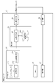
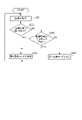
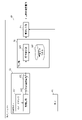
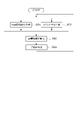
- FIG. 5 is a flowchart showing an example of processing of the HMD unit 20 according to the first embodiment.
- the image sensor 211 of the RGB camera 21 generates the RGB image signal 213 (step S101).
- the calculation unit 24 calculates the coordinate information regarding the user (step S102), and the information output unit 25 outputs the coordinate information and the posture information (step S103).
- the HMD unit 20 can continuously supply various information indicating the user's state to the information processing apparatus 30.
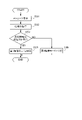
- step S201 acquires various information supplied from the HMD unit 20
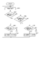
- step S202 determines whether or not the coordinate information output from the HMD unit 20 includes the user's face or head. If this is the case (step S202NO), the process proceeds to step S204 described later, and if it is determined that the coordinate information includes the user's face or head (step S202YES), the determination unit 321 is determined to be in the second imaging mode. (Step S203).
- the determination unit 321 determines whether or not the user's hand is in front of the arm in the coordinate information output from the HMD unit 20. If it is determined in the coordinate information that the user's hand is not in front of the arm (step S204NO), the process proceeds to step S205 described later, and it is determined in the coordinate information that the user's hand is in front of the arm. If so (step S204YES), the process returns to step S203. When it is determined in the coordinate information that the user's hand is not in front of the arm (step S204NO), it is determined that the determination unit 321 is in the first imaging mode (step S205).
- the control unit 32 After determining the imaging mode in step S203 or step S205, the control unit 32 returns to step S201 again and repeats the process to continuously determine the imaging mode. If the imaging mode is not determined even after a predetermined time has elapsed, the control unit 32 may perform the following processing. In the example illustrated in FIG. 7, the control unit 32 displays a message urging the user to take a specific pose on the display unit 27 of the HMD unit 20 and the display unit 52 of the display device 50 (step S301). Here, for example, the message "Please show the palms of both hands" is displayed. Next, the communication unit 31 acquires various information supplied from the HMD unit 20 again (step S302).
- the determination unit 321 determines whether or not the user's thumb is facing outward in the coordinate information output from the HMD unit 20 (step S303), and determines in the coordinate information that the user's thumb is facing outward. If this is the case (step S303YES), the determination unit 321 determines that it is in the first imaging mode (step S304), and if it is determined in the coordinate information that the user's thumb is not facing outward (step S303NO), The determination unit 321 determines that the second imaging mode is set (step S305).
- an error message is displayed on the display unit 27 of the HMD unit 20 and the display unit 52 of the display device 50. It may be configured to notify the user. Further, as shown in FIG. 7, if the image pickup mode is not determined even if the user is urged to take a specific pose and the determination is made, the user may be notified as described above.
- the control unit 32 When the user changes the image pickup mode according to the content of the game to be played, the subject (field) to be imaged by the RGB camera 21 changes, and as a result, the content of the RGB image signal 213 changes. Change. Then, when the content of the RGB image signal 213 changes, the change is reflected in the coordinate information calculated based on the RGB image signal 213. As described above, the control unit 32 once determines the imaging mode, and then repeats the process. Therefore, in the system 1, the image pickup mode can be determined based on the coordinate information according to the change of the image pickup mode.
- the HMD unit 20 includes an image sensor 211 which is a first image sensor, a first image pickup mode for capturing images from the user's first-person viewpoint, and a user's first image sensor. Imaging is performed by one of the second imaging modes in which the user is imaged from the third person viewpoint. Then, the calculation unit 24 recognizes the user based on the RGB image signal 213 and calculates the coordinate information about the user. Then, the determination unit 321 of the information processing apparatus 30 determines which of the first imaging mode and the second imaging mode is performing imaging based on the coordinate information, and determines the first imaging mode.
- the control unit 32 performs the first process based on the coordinate information calculated in the first imaging mode, and when it is determined to be the second imaging mode, the control unit 32 calculates in the second imaging mode.
- the second process is performed based on the coordinate information. Therefore, the user can perform appropriate processing without making special settings for the first imaging mode and the second imaging mode, which is highly convenient for the user and can accurately perform processing according to the imaging mode. ..
- the HMD unit 20 of the first embodiment can accept the user operation by calculating the coordinate information about the user, the user can maintain the cursor position in order to maintain the cursor position as in the conventional pointing device type operating device. It does not cause physical fatigue. Further, the HMD unit 20 does not need to have the user wear a marker or an attachment to be recognized unlike the conventional posture detection type operation device.
- the coordinate information includes at least one of the coordinate information of the feature point regarding the posture of the user, the feature point regarding the shape of the arm of the user, or the feature point regarding the shape of the finger of the user. Therefore, it is possible to grasp the characteristic state of the user and calculate the coordinate information.
- the calculation unit 24 of the HMD unit 20 has been learned by learning the relationship between the image of a person having a plurality of joints and the coordinate information indicating the positions of the plurality of joints. Based on the model 242, the coordinate information of at least one joint of the person included in the image based on the RGB image signal 213 is calculated. Therefore, the coordinate information about the user can be calculated accurately and at high speed.
- the HMD unit 20 is provided with a mounting portion 20A that can be mounted on the user's body. Therefore, when the HMD unit 20 is mounted on the user's head by the mounting portion 20A, imaging is performed in the first imaging mode, and the mounting portion 20A places the HMD unit 20 on a table or the like without mounting it on the user's head. When placed, it is possible to perform imaging in the second imaging mode.
- FIG. 8 is a schematic diagram showing the entire system 2 according to the second embodiment of the present invention
- FIG. 9 is a block diagram showing a schematic configuration of the system 2.
- the system 2 according to the second embodiment is a game system including a camera unit 60 which is a second sensor device in addition to the system 1 of the first embodiment.
- the system 2 includes an information processing device 70 instead of the information processing device 30 of the system 1 of the first embodiment.
- the camera unit 60 calculates the coordinate information about the user who is the player of the game and transmits it to the information processing apparatus 70, similarly to the HMD unit 20. That is, the camera unit 60 functions as an operating device for accepting user operations, like the HMD unit 20 and the controller 40, by calculating and outputting coordinate information about the user.
- the camera unit 60 is an imaging device for performing imaging in the second imaging mode described in the first embodiment. The optimum arrangement of the camera unit 60 is the same as when the HMD unit 20 of the first embodiment performs imaging in the second imaging mode.
- FIG. 10 is a block diagram showing a schematic configuration of the camera unit 60.
- the camera unit 60 includes an RGB camera 61, an IMU 63, a calculation unit 64 that functions as a first arithmetic processing device, and an information output unit 65.
- Each of the RGB camera 61, IMU 63, calculation unit 64, and information output unit 65 has the same configuration as the RGB camera 21, IMU 23, calculation unit 24, and information output unit 25 of the HMD unit 20 of the first embodiment, respectively. ..
- the RGB camera 61 generates an RGB image signal 613 by the image sensor 611 and the processing circuit 612 having the same configuration as the image sensor 211 and the processing circuit 212 of the RGB camera 21 of the first embodiment.
- the calculation unit 64 is an RGB image signal generated by the RGB camera 61 by the coordinate calculation unit 241 of the calculation unit 24 of the first embodiment, the coordinate calculation unit 641 having the same configuration as the trained model 242, and the trained model 642. Coordinate information about the user is calculated based on 613.
- the information output unit 65 outputs the coordinate information about the user calculated by the calculation unit 64 and the posture information acquired by the IMU 63 to the information processing device 70.
- the camera unit 60 completes the process from the generation of the RGB image signal 613 to the calculation of the coordinate information about the user by itself, and the information processing apparatus 70 is provided with the information processing unit 60.
- the calculated coordinate information and attitude information can be output without outputting the RGB image signal 613.
- the camera unit 60 preferably has an independent power supply.
- 11A and 11B are diagrams illustrating an imaging mode according to the second embodiment.
- the HMD unit 20 performs the imaging in the first imaging mode
- the camera unit 60 performs the imaging in the second imaging mode.
- the first imaging mode imaging is performed by the HMD unit 20 mounted on the user's head.
- the second imaging mode imaging is performed by the camera unit 60 placed on a table or the like. Therefore, as in the first embodiment, the subject included in the image data based on the generated image signal is different in the first image pickup mode and the second image pickup mode of the second embodiment.
- the information processing apparatus 70 includes a communication unit 71 in place of the communication unit 31 of the information processing apparatus 30 of the first embodiment, and includes a control unit 72 in place of the control unit 32.
- the communication unit 71 includes the coordinate information about the user and the posture information output from the information output unit 65 of the camera unit 60. Is received, and a display image to be displayed on the display unit 27 of the HMD unit 20 is output.
- the coordinate information about the user output from the information output unit 25 of the HMD unit 20 is referred to as the coordinate information C 20
- the coordinate information about the user output from the information output unit 65 of the camera unit 60 is referred to as the coordinate information C 20. It is referred to as coordinate information C 60 .
- the control unit 72 includes the function of the determination unit 721 in place of the determination unit 321 of the control unit 32 of the information processing apparatus 30 of the first embodiment, and includes the function of the control value calculation unit 722 in place of the control value calculation unit 322.
- the function of the image generation unit 723 is included in place of the image generation unit 323.
- the determination unit 721 is performing imaging in either the first imaging mode or the second imaging mode based on the coordinate information C 20 output from the HMD unit 20 or the coordinate information C 60 output from the camera unit 60. To judge. The determination is performed in the same manner as in the information processing apparatus 30 of the first embodiment.
- the control value calculation unit 722 calculates the control value of the feedback control to the external device including the HMD unit 20, the controller 40, and the display device 50 according to the image pickup mode determined by the determination unit 721.
- the HMD unit 20, the controller 40, and the camera unit 60 function as operating devices for accepting user operations. Therefore, the control value calculation unit 722 is an external device including the HMD unit 20, the controller 40, and the display device 50 according to the user operation performed via any of the HMD unit 20, the controller 40, and the camera unit 60.
- the image generation unit 723 generates a display image showing the user's state according to the image pickup mode determined by the determination unit 721.
- the display image is generated in the same manner as in the information processing apparatus 30 of the first embodiment.
- the controller 40 has the same configuration and function as that of the first embodiment.
- the control value calculation unit 722 of the information processing apparatus 70 calculates the control value of the feedback control to the controller 40, but when the determination unit 721 determines that the first imaging mode is set, the control value calculation unit 722. Calculates the control value of the feedback control to the controller 40 based on the coordinate information C 20 output from the HMD unit 20. By calculating the control value using the coordinate information C 20 output from the HMD unit 20, the first process based on the first imaging mode using the HMD unit 20 as an operating device can be performed.
- the control value calculation unit 722 calculates the control value of the feedback control to the controller 40 based on the coordinate information C 60 output from the camera unit 60. .. By calculating the control value using the coordinate information C 60 output from the camera unit 60, the second process based on the second imaging mode using the camera unit 60 as an operating device can be performed.
- the display device 50 has the same configuration and function as that of the first embodiment.
- the control value calculation unit 722 of the information processing device 70 calculates the control value of the feedback control to the display image displayed on the display unit 27 of the HMD unit 20 and the display unit 52 of the display device 50.
- the determination unit 721 determines the first imaging mode
- the control value calculation unit 722 calculates the control value of the feedback control to the display image based on the coordinate information C 20 output from the HMD unit 20. By calculating the control value using the coordinate information C 20 output from the HMD unit 20, processing based on the first imaging mode using the HMD unit 20 as an operating device can be performed.
- the control value calculation unit 722 calculates the control value of the feedback control to the display image based on the coordinate information C 60 output from the camera unit 60. .. By calculating the control value using the coordinate information C 60 output from the camera unit 60, it is possible to perform processing based on the second imaging mode using the camera unit 60 as an operating device.
- FIG. 12 is a flowchart showing an example of processing of the information processing apparatus 70 according to the second embodiment.
- the communication unit 71 acquires various information supplied from each of the HMD unit 20 and the camera unit 60 (step S401).
- the determination unit 721 determines whether or not the coordinate information C 60 output from the camera unit 60 includes the user's face or head (step S402), and the coordinate information C 60 does not include the user's face or head. If it is determined (step S402NO), the process proceeds to step S405 described later, and if it is determined that the coordinate information C 60 includes the user's face or head (step S402YES), the coordinate information output from the camera unit 60 is determined. It is determined whether or not C 60 can be used (step S403).
- Whether or not the coordinate information C 60 can be used can be determined based on, for example, whether or not the control value based on the coordinate information C 60 can be calculated.
- step S403YES it is determined that the determination unit 721 is in the second imaging mode (step S404).
- step S403NO the determination unit 721 cannot determine the imaging mode, so the process returns to step S401.
- step S402NO When it is determined that the coordinate information C 60 does not include the user's face or head (step S402NO), whether the determination unit 721 has the user's hand in front of the arm in the coordinate information C 60 output from the camera unit 60. If it is determined whether or not (step S405) and it is determined in the coordinate information C 60 that the user's hand is not in front of the arm (step S405 NO), the process proceeds to step S406 described later, and the user's hand is in the coordinate information C 60 . If it is determined that the arm is in front of the arm (step S405YES), the process returns to step S403.
- the determination unit 721 determines in the coordinate information C 60 that the user's hand is not in front of the arm (step S405NO), it determines whether or not the coordinate information C 20 output from the HMD unit 20 can be used (step). S406). Whether or not the coordinate information C 20 can be used can be determined based on whether or not the control value based on the coordinate information C 20 can be calculated. When it is determined that the coordinate information C 20 can be used (step S406YES), it is determined that the determination unit 721 is in the first imaging mode (step S407). On the other hand, when it is determined that the coordinate information C 20 cannot be used (step S406NO), the determination unit 721 cannot determine the imaging mode, so the process returns to step S401.
- the control unit 72 After determining the imaging mode in step S404 or step S407, the control unit 72 returns to step S401 again and repeats the process to continuously determine the imaging mode. Further, if the image pickup mode is not determined even after a predetermined time has elapsed, as in the control unit 32 of the first embodiment, the configuration is such that the user is urged to take a specific pose and the determination is performed. Alternatively, the user may be notified by displaying an error message on the display unit 27 of the HMD unit 20 and the display unit 52 of the display device 50. Further, if the image pickup mode is not determined even if the user is urged to take a specific pose and the determination is made, the user may be notified as described above.
- the determination unit 721 outputs from the camera unit 60 whether or not the user's thumb is facing outward in the coordinate information C 20 output from the HMD unit 20.
- the image pickup mode can be determined by determining at least one of whether or not the user's thumb is facing inward in the coordinate information C60 .
- the HMD unit 20 which is the first image pickup apparatus in which the system 2 performs image pickup in the first image pickup mode and the second image pickup in which image pickup is performed in the second image pickup mode.
- the determination unit 721 includes the camera unit 60, which is an apparatus, and determines whether the image is taken by the HMD unit 20 or the camera unit 60. Then, when it is determined that the image is being taken by the HMD unit 20, the control unit 72 performs the first process based on the coordinate information C 20 output from the HMD unit 20, and the camera unit 60 takes an image. When it is determined that the above is performed, the control unit 72 performs the second processing based on the coordinate information C 60 output from the camera unit 60. Therefore, when the HMD unit 20 and the camera unit 60 are used in combination, the same effect as that of the first embodiment can be obtained.
- the camera unit 60 performs from the generation of the RGB image signal 613 to the calculation of the coordinate information regarding the user, and the coordinate information and the image sensor 611 are not output without outputting the RGB image signal 613.
- the attitude information of it is possible to reduce the problems of communication load and communication delay. Further, since it is not necessary to output the RGB image signal 613, it is also useful in terms of privacy protection.
- the system 3 according to the third embodiment includes the same information processing device 30, the controller 40, and the display device 50 as the system 1 of the first embodiment, and the HMD unit 20 of the system 1. Instead of, it is a game system including an HMD unit 80.
- FIG. 13 is a block diagram showing a schematic configuration of the HMD unit 80 in the system 3. Similar to the HMD unit 20 of the system 1 of the first embodiment, the HMD unit 80 includes an RGB camera 81, an IMU 83, a calculation unit 84 that functions as a first arithmetic processing device, an information output unit 85, and a reception unit. It includes 86, a display unit 87, and an EDS (Event Driven Sensor) 82, which is a second imaging device.
- RGB camera 81, IMU83, calculation unit 84, The information output unit 85, the reception unit 86, and the display unit 87 are the RGB camera 21, IMU 23, calculation unit 24, information output unit 25, reception unit 26, and display unit 27 of the HMD unit 20 of the first embodiment, respectively. It has the same configuration as.
- the RGB camera 81 generates an RGB image signal 813 by an image sensor 811 and a processing circuit 812 having the same configuration as the image sensor 211 and the processing circuit 212 of the RGB camera 21 of the first embodiment.
- the EDS 82 includes a sensor 821 which is a second image sensor constituting the sensor array, and a processing circuit 822 connected to the sensor 821.
- the sensor 821 includes a light receiving element, and generates an event signal 823 which is a second image signal when it detects a change in the intensity of light incident on each pixel, more specifically, a change in luminance exceeding a predetermined predetermined value. It is an event-driven vision sensor.
- the event signal 823 output via the processing circuit 822 includes the identification information of the sensor 821 (for example, the position of the pixel), the polarity (increased or decreased) of the luminance change, and the time stamp.
- the EDS 82 can generate the event signal 823 at a frequency significantly higher than the frequency of generating the RGB image signal 813 (frame rate of the RGB camera 81).
- a signal capable of constructing an image based on the signal is referred to as an image signal. Therefore, the RGB image signal 813 and the event signal 823 show an example of an image signal.
- the time stamps given to the RGB image signal 813 and the event signal 823 are synchronized. Specifically, for example, by providing the RGB camera 81 with the time information used for generating the time stamp in the EDS 82, the time stamps given to the RGB image signal 813 and the event signal 823 can be synchronized. Alternatively, when the time information for generating the time stamp is independent for the RGB camera 81 and the EDS 82, the time stamp is based on the time when a specific event (for example, a change in the subject over the entire image) occurs. By calculating the offset amount, the time stamps given to the RGB image signal 813 and the event signal 823 can be synchronized after the fact.
- a specific event for example, a change in the subject over the entire image
- the sensor 821 of the EDS 82 is associated with one or a plurality of pixels of the RGB image signal 813 by the calibration procedure of the RGB camera 81 and the EDS 82 executed in advance, and the event signal 823 is RGB. It is generated according to the change in light intensity in one or more pixels of the image signal 813. More specifically, for example, a calibration pattern common to the RGB camera 81 and the EDS 82 is imaged, and the corresponding parameters between the camera and the sensor are obtained from the internal and external parameters of the RGB camera 81 and the EDS 82, respectively. By calculation, the sensor 821 can be associated with one or more pixels of the RGB image signal 813.
- the IMU83 is an inertial sensor that detects the attitudes of the image sensor 811 and the sensor 821, and acquires three-dimensional attitude information of the image sensor 811 and the sensor 821 at a predetermined cycle or at a predetermined timing, and information the attitude information. Output to the output unit 85.
- the calculation unit 84 includes the coordinate calculation unit 841 and the trained model 842, and calculates the coordinate information about the user based on the event signal 823 generated by the EDS 82 and the RGB image signal 813 generated by the RGB camera 81. do.
- the coordinate calculation unit 841 of the calculation unit 84 detects, for example, an object existing in a continuous pixel region in which an event of the same polarity is shown to occur in the event signal 823, and determines the corresponding portion of the RGB image signal 813.
- the user is recognized by performing subject recognition based on the subject.
- the coordinate calculation unit 841 identifies each user.
- the coordinate calculation unit 841 calculates the coordinate information indicating the positions of the plurality of joints of the user from the RGB image signal 813 based on the learned model 842 for each recognized user.
- the positions of the plurality of joints possessed by the user correspond to the feature points relating to the posture of the user, the feature points relating to the shape of the arm of the user, or the feature points relating to the shape of the finger of the user. Since the trained model 842 is the same as that of the first embodiment, the description thereof will be omitted.
- the information output unit 85 outputs the coordinate information about the user calculated by the calculation unit 84 and the posture information acquired by the IMU 83 to the information processing apparatus 30.
- the receiving unit 86 and the display unit 87 have the same configuration as the receiving unit 26 and the display unit 27 of the HMD unit 20 of the first embodiment.
- the HMD unit 80 like the HMD unit 20 of the first embodiment, completes the process from the generation of the RGB image signal 813 and the event signal 823 to the calculation of the coordinate information about the user by itself, and performs information processing.
- the calculated coordinate information and attitude information can be output without outputting the RGB image signal 813 and the event signal 823 to the device 30.
- the HMD unit 80 has an independent power supply as in the HMD unit 20 of the first embodiment.
- Each part of the information processing device 30, the controller 40, and the display device 50 has the same configuration and function as that of the first embodiment.
- FIG. 14 is a flowchart showing an example of processing of the HMD unit 80 according to the third embodiment.
- the image sensor 811 of the RGB camera 81 generates the RGB image signal 813 (step S501), and the sensor 821 of the EDS 82 generates the event signal 823 (step S502).
- the calculation unit 84 calculates the coordinate information regarding the user (step S503), and the information output unit 85 outputs the coordinate information and the posture information (step S504).
- the HMD unit 80 can continuously supply various information indicating the user's state to the information processing apparatus 30.
- the HMD unit 80 calculates coordinate information about the user based on the RGB image signal 813 and the event signal 823 generated by the image sensor 811 and the sensor 821, respectively. Output to the information processing device 30. Therefore, as in the first embodiment, the user can perform appropriate processing without making any special settings regarding the first imaging mode and the second imaging mode, which is highly convenient for the user and accurately sets the imaging mode. It is possible to perform the corresponding processing. Further, by using the sensor 821 that generates the event signal 823, it is possible to perform processing accurately according to the imaging mode while suppressing the latency.
- the system 3 including the HMD unit 80 having the EDS 82 in addition to the RGB camera 81 has been described as an example.
- the configuration may include an HMD unit having an EDS in addition to the RGB camera.
- a camera unit having an EDS may be included in addition to the RGB camera. In either case, by using a sensor that generates an event signal, it is possible to perform processing accurately according to the imaging mode while suppressing latency.
- FIG. 15 is a block diagram showing a schematic configuration of the system 4 according to the fourth embodiment.
- the system 4 according to the fourth embodiment is a game system including a server 90 and a terminal device 100 in place of the information processing device 30 of the system 1 of the first embodiment.
- the server 90 is a server (for example, a cloud server) that is connected to the HMD unit 20 and the terminal device 100 via an Internet communication network or wirelessly.
- the server 90 has the same configuration as the information processing apparatus 30 of the first embodiment, and performs various processes based on the information output by the HMD unit 20.
- the terminal device 100 includes a communication unit 101, and the communication unit 101 receives the information output from the server 90.
- the communication unit 101 can communicate with the controller 40 and outputs an image to be displayed on the HMD unit 20 and the display device 50, similarly to the communication unit 31 of the information processing device 30 of the first embodiment.
- the HMD unit 20 performs from the generation of the RGB image signal 213 to the calculation of the coordinate information, and outputs only the coordinate information to the server 90, so that even in a game system using a server such as a cloud server.
- a server such as a cloud server.
- a similar effect can be obtained.
- the same effect can be obtained by applying the server to the system 2 described in the second embodiment and the system 3 described in the third embodiment in the same manner.
- a part of the processing performed by the information processing apparatus may be performed by the HMD unit and the camera unit.
- the function of the determination unit 321 in the information processing apparatus 30 of the first embodiment may be provided in the HMD unit 20.
- the function of the determination unit 721 in the information processing apparatus 70 of the second embodiment may be provided in the HMD unit 20 and the camera unit 60.
- the HMD unit 20 and the camera unit 60 may change the method of calculating the coordinate information, more specifically, the trained model, according to the determined imaging mode.
- the number of RGB cameras and EDSs of the HMD unit may be the same or different. Further, the number of RGB cameras and EDS may be one or a plurality. For example, when a plurality of RGB cameras are provided, the range of the field for generating RGB image signals can be expanded, and the state of a person can be estimated three-dimensionally from the plurality of RGB image signals. Further, for example, when a plurality of EDS 12s are provided, it is possible to expand the range of the field in which the event signal is generated, or to calculate the three-dimensional movement amount of the person based on the plurality of event signals. can. The same applies to the RGB camera and EDS of the camera unit.
- the HMD unit and the camera unit described in each of the above embodiments may be mounted in a single device or may be mounted in a plurality of devices in a distributed manner.
- at least a part of each sensor may be independently provided, and other configurations may be implemented as an HMD unit and a camera unit main body.
- image sensor 212, 612, 812, 822 ... processing circuit, 213, 613, 813 ... RGB image signal, 241, 641, 841 ... coordinate calculation unit, 242, 642, 842 ... trained model, 321, 721. ... Judgment unit, 322, 722 ... Control value calculation unit, 323, 723 ... Image generation unit, 821 ... Sensor, 823 ... Event signal.
Landscapes
- Engineering & Computer Science (AREA)
- Multimedia (AREA)
- Theoretical Computer Science (AREA)
- Human Computer Interaction (AREA)
- Physics & Mathematics (AREA)
- General Physics & Mathematics (AREA)
- General Engineering & Computer Science (AREA)
- Computer Hardware Design (AREA)
- Signal Processing (AREA)
- Computer Vision & Pattern Recognition (AREA)
- User Interface Of Digital Computer (AREA)
- Studio Devices (AREA)
- Image Processing (AREA)
- Position Input By Displaying (AREA)
- Image Analysis (AREA)
Priority Applications (2)
| Application Number | Priority Date | Filing Date | Title |
|---|---|---|---|
| EP21897808.8A EP4252871A4 (en) | 2020-11-25 | 2021-11-16 | SYSTEM, IMAGING DEVICE, INFORMATION PROCESSING DEVICE, INFORMATION PROCESSING METHOD AND INFORMATION PROCESSING PROGRAM |
| US18/253,070 US12401883B2 (en) | 2020-11-25 | 2021-11-16 | System, imaging apparatus, information processing apparatus, information processing method, and information processing program |
Applications Claiming Priority (2)
| Application Number | Priority Date | Filing Date | Title |
|---|---|---|---|
| JP2020195149A JP7394046B2 (ja) | 2020-11-25 | 2020-11-25 | システム、撮像装置、情報処理装置、情報処理方法および情報処理プログラム |
| JP2020-195149 | 2020-11-25 |
Publications (1)
| Publication Number | Publication Date |
|---|---|
| WO2022113834A1 true WO2022113834A1 (ja) | 2022-06-02 |
Family
ID=81755960
Family Applications (1)
| Application Number | Title | Priority Date | Filing Date |
|---|---|---|---|
| PCT/JP2021/042137 Ceased WO2022113834A1 (ja) | 2020-11-25 | 2021-11-16 | システム、撮像装置、情報処理装置、情報処理方法および情報処理プログラム |
Country Status (4)
| Country | Link |
|---|---|
| US (1) | US12401883B2 (cg-RX-API-DMAC7.html) |
| EP (1) | EP4252871A4 (cg-RX-API-DMAC7.html) |
| JP (1) | JP7394046B2 (cg-RX-API-DMAC7.html) |
| WO (1) | WO2022113834A1 (cg-RX-API-DMAC7.html) |
Families Citing this family (1)
| Publication number | Priority date | Publication date | Assignee | Title |
|---|---|---|---|---|
| JP7434207B2 (ja) * | 2021-04-13 | 2024-02-20 | 株式会社ソニー・インタラクティブエンタテインメント | システム、情報処理方法および情報処理プログラム |
Citations (5)
| Publication number | Priority date | Publication date | Assignee | Title |
|---|---|---|---|---|
| US20090131171A1 (en) | 2007-11-16 | 2009-05-21 | Sony Computer Entertainment Inc. | Game System and Game Controller |
| JP2014115457A (ja) * | 2012-12-10 | 2014-06-26 | Sony Corp | 情報処理装置および記録媒体 |
| JP2014127987A (ja) * | 2012-12-27 | 2014-07-07 | Sony Corp | 情報処理装置および記録媒体 |
| US20150109528A1 (en) * | 2013-10-21 | 2015-04-23 | Postech Academy-Industry Foundation | Apparatus and method for providing motion haptic effect using video analysis |
| JP2019213764A (ja) * | 2018-06-14 | 2019-12-19 | 株式会社バンダイナムコスタジオ | シミュレーションシステム |
Family Cites Families (27)
| Publication number | Priority date | Publication date | Assignee | Title |
|---|---|---|---|---|
| US6766036B1 (en) * | 1999-07-08 | 2004-07-20 | Timothy R. Pryor | Camera based man machine interfaces |
| KR100840023B1 (ko) * | 2007-11-13 | 2008-06-20 | (주)올라웍스 | 셀프 촬영 시 얼굴의 구도를 잡도록 도와주는 방법 및시스템 |
| US8538072B2 (en) * | 2008-08-27 | 2013-09-17 | Imprivata, Inc. | Systems and methods for operator detection |
| US20100295782A1 (en) * | 2009-05-21 | 2010-11-25 | Yehuda Binder | System and method for control based on face ore hand gesture detection |
| CN101827219B (zh) * | 2010-01-22 | 2014-07-16 | 中兴通讯股份有限公司 | 无线终端中主从模式双摄像头控制方法及装置 |
| JP5300777B2 (ja) * | 2010-03-31 | 2013-09-25 | 株式会社バンダイナムコゲームス | プログラム及び画像生成システム |
| US8350919B2 (en) * | 2010-09-09 | 2013-01-08 | Vizio, Inc. | Configuration of a device based upon orientation |
| US8643741B2 (en) * | 2012-01-17 | 2014-02-04 | Apple Inc. | Orientation detection using image processing |
| US10002297B2 (en) * | 2012-06-20 | 2018-06-19 | Imprivata, Inc. | Active presence detection with depth sensing |
| US20140184854A1 (en) * | 2012-12-28 | 2014-07-03 | Motorola Mobility Llc | Front camera face detection for rear camera zoom function |
| JP6143469B2 (ja) * | 2013-01-17 | 2017-06-07 | キヤノン株式会社 | 情報処理装置、情報処理方法及びプログラム |
| KR102020636B1 (ko) * | 2013-06-07 | 2019-09-10 | 삼성전자주식회사 | 카메라에 기반한 전자 장치의 제어 방법, 저장 매체 및 전자 장치 |
| US9630105B2 (en) * | 2013-09-30 | 2017-04-25 | Sony Interactive Entertainment Inc. | Camera based safety mechanisms for users of head mounted displays |
| US9536351B1 (en) * | 2014-02-03 | 2017-01-03 | Bentley Systems, Incorporated | Third person view augmented reality |
| US9363426B2 (en) * | 2014-05-29 | 2016-06-07 | International Business Machines Corporation | Automatic camera selection based on device orientation |
| JP6426484B2 (ja) * | 2015-01-28 | 2018-11-21 | 京セラ株式会社 | 携帯端末 |
| JP6691351B2 (ja) * | 2015-03-31 | 2020-04-28 | 株式会社バンダイナムコエンターテインメント | プログラム及びゲームシステム |
| US9860452B2 (en) * | 2015-05-13 | 2018-01-02 | Lenovo (Singapore) Pte. Ltd. | Usage of first camera to determine parameter for action associated with second camera |
| WO2017150795A1 (en) | 2016-02-29 | 2017-09-08 | Samsung Electronics Co., Ltd. | Video display apparatus and method for reducing vr sickness |
| US9832368B1 (en) * | 2016-05-31 | 2017-11-28 | Motorola Mobility Llc | Managing unintended camera clicks |
| US10095461B2 (en) * | 2016-09-23 | 2018-10-09 | Intel IP Corporation | Outside-facing display for head-mounted displays |
| US10440261B2 (en) * | 2017-04-03 | 2019-10-08 | International Business Machines Corporation | Automatic selection of a camera based on facial detection |
| US10430966B2 (en) * | 2017-04-05 | 2019-10-01 | Intel Corporation | Estimating multi-person poses using greedy part assignment |
| US10803616B1 (en) * | 2017-04-13 | 2020-10-13 | Facebook Technologies, Llc | Hand calibration using single depth camera |
| US20180356880A1 (en) * | 2017-04-14 | 2018-12-13 | Colopl, Inc. | Information processing method and apparatus, and program for executing the information processing method on computer |
| US10688396B2 (en) * | 2017-04-28 | 2020-06-23 | Sony Interactive Entertainment Inc. | Second screen virtual window into VR environment |
| US10812731B2 (en) * | 2018-08-22 | 2020-10-20 | Qualcomm Incorporated | Adjustable receiver exposure times for active depth sensing systems |
-
2020
- 2020-11-25 JP JP2020195149A patent/JP7394046B2/ja active Active
-
2021
- 2021-11-16 US US18/253,070 patent/US12401883B2/en active Active
- 2021-11-16 EP EP21897808.8A patent/EP4252871A4/en active Pending
- 2021-11-16 WO PCT/JP2021/042137 patent/WO2022113834A1/ja not_active Ceased
Patent Citations (5)
| Publication number | Priority date | Publication date | Assignee | Title |
|---|---|---|---|---|
| US20090131171A1 (en) | 2007-11-16 | 2009-05-21 | Sony Computer Entertainment Inc. | Game System and Game Controller |
| JP2014115457A (ja) * | 2012-12-10 | 2014-06-26 | Sony Corp | 情報処理装置および記録媒体 |
| JP2014127987A (ja) * | 2012-12-27 | 2014-07-07 | Sony Corp | 情報処理装置および記録媒体 |
| US20150109528A1 (en) * | 2013-10-21 | 2015-04-23 | Postech Academy-Industry Foundation | Apparatus and method for providing motion haptic effect using video analysis |
| JP2019213764A (ja) * | 2018-06-14 | 2019-12-19 | 株式会社バンダイナムコスタジオ | シミュレーションシステム |
Non-Patent Citations (1)
| Title |
|---|
| See also references of EP4252871A4 |
Also Published As
| Publication number | Publication date |
|---|---|
| EP4252871A4 (en) | 2024-09-18 |
| US12401883B2 (en) | 2025-08-26 |
| US20230353860A1 (en) | 2023-11-02 |
| EP4252871A1 (en) | 2023-10-04 |
| JP2022083680A (ja) | 2022-06-06 |
| JP7394046B2 (ja) | 2023-12-07 |
Similar Documents
| Publication | Publication Date | Title |
|---|---|---|
| US10620699B2 (en) | Head mounted display, mobile information terminal, image processing apparatus, display control program, display control method, and display system | |
| US11086392B1 (en) | Devices, systems, and methods for virtual representation of user interface devices | |
| CN116348836A (zh) | 增强现实中用于交互式游戏控制的手势跟踪 | |
| US20190240573A1 (en) | Method for controlling characters in virtual space | |
| CN112312979A (zh) | 电磁场上的头戴式显示器与控制器的时钟同步 | |
| US20100128112A1 (en) | Immersive display system for interacting with three-dimensional content | |
| US20120135803A1 (en) | Game device utilizing stereoscopic display, method of providing game, recording medium storing game program, and game system | |
| JP2003337963A (ja) | 画像処理装置および画像処理方法、ならびに、画像処理プログラムおよびその記録媒体 | |
| US11567330B2 (en) | Display control apparatus, display control method, and display control program | |
| WO2019155840A1 (ja) | 情報処理装置、情報処理方法、およびプログラム | |
| KR20150040580A (ko) | 가상 공간 멀티 터치 인터랙션 장치 및 방법 | |
| CN113365085B (zh) | 一种直播视频生成方法及装置 | |
| JP7300436B2 (ja) | 情報処理装置、システム、情報処理方法および情報処理プログラム | |
| JP7394046B2 (ja) | システム、撮像装置、情報処理装置、情報処理方法および情報処理プログラム | |
| US12528015B2 (en) | Information processing apparatus, information processing method, and driving data generation method | |
| JP7513564B2 (ja) | システム、情報処理方法および情報処理プログラム | |
| CN118747039A (zh) | 用于移动虚拟对象的方法、装置、电子设备和存储介质 | |
| CN113617023B (zh) | 程序、信息处理方法、信息处理装置以及信息处理系统 | |
| JP7434207B2 (ja) | システム、情報処理方法および情報処理プログラム | |
| KR20250019680A (ko) | 정보 처리 장치, 컨트롤러 표시 방법 및 컴퓨터 프로그램 | |
| US20260069982A1 (en) | Information processing device and image generation method | |
| US20260105700A1 (en) | Information processing apparatus and information processing method | |
| EP4610785A1 (en) | Input device, control apparatus, control method, information processing apparatus, and information processing method | |
| JP2025078532A (ja) | 情報処理装置、情報処理装置のシステム、情報処理装置の制御方法、プログラム | |
| KR20250002501A (ko) | Xr 디바이스, xr 디바이스의 컨트롤러 장치, 이들을 이용한 xr 디바이스의 동작 방법 |
Legal Events
| Date | Code | Title | Description |
|---|---|---|---|
| 121 | Ep: the epo has been informed by wipo that ep was designated in this application |
Ref document number: 21897808 Country of ref document: EP Kind code of ref document: A1 |
|
| NENP | Non-entry into the national phase |
Ref country code: DE |
|
| ENP | Entry into the national phase |
Ref document number: 2021897808 Country of ref document: EP Effective date: 20230626 |
|
| WWG | Wipo information: grant in national office |
Ref document number: 18253070 Country of ref document: US |