WO2022113789A1 - アタッチメント、及びこれを備えた給湯用具 - Google Patents
アタッチメント、及びこれを備えた給湯用具 Download PDFInfo
- Publication number
- WO2022113789A1 WO2022113789A1 PCT/JP2021/041806 JP2021041806W WO2022113789A1 WO 2022113789 A1 WO2022113789 A1 WO 2022113789A1 JP 2021041806 W JP2021041806 W JP 2021041806W WO 2022113789 A1 WO2022113789 A1 WO 2022113789A1
- Authority
- WO
- WIPO (PCT)
- Prior art keywords
- attachment
- main body
- push button
- hot water
- discharge port
- Prior art date
- Legal status (The legal status is an assumption and is not a legal conclusion. Google has not performed a legal analysis and makes no representation as to the accuracy of the status listed.)
- Ceased
Links
Images







Classifications
-
- B—PERFORMING OPERATIONS; TRANSPORTING
- B67—OPENING, CLOSING OR CLEANING BOTTLES, JARS OR SIMILAR CONTAINERS; LIQUID HANDLING
- B67D—DISPENSING, DELIVERING OR TRANSFERRING LIQUIDS, NOT OTHERWISE PROVIDED FOR
- B67D1/00—Apparatus or devices for dispensing beverages on draught
- B67D1/08—Details
- B67D1/12—Flow or pressure control devices or systems, e.g. valves, gas pressure control, level control in storage containers
-
- A—HUMAN NECESSITIES
- A47—FURNITURE; DOMESTIC ARTICLES OR APPLIANCES; COFFEE MILLS; SPICE MILLS; SUCTION CLEANERS IN GENERAL
- A47J—KITCHEN EQUIPMENT; COFFEE MILLS; SPICE MILLS; APPARATUS FOR MAKING BEVERAGES
- A47J31/00—Apparatus for making beverages
- A47J31/44—Parts or details or accessories of beverage-making apparatus
- A47J31/46—Dispensing spouts, pumps, drain valves or like liquid transporting devices
-
- B—PERFORMING OPERATIONS; TRANSPORTING
- B67—OPENING, CLOSING OR CLEANING BOTTLES, JARS OR SIMILAR CONTAINERS; LIQUID HANDLING
- B67D—DISPENSING, DELIVERING OR TRANSFERRING LIQUIDS, NOT OTHERWISE PROVIDED FOR
- B67D1/00—Apparatus or devices for dispensing beverages on draught
- B67D1/0003—Apparatus or devices for dispensing beverages on draught the beverage being a single liquid
- B67D1/0014—Apparatus or devices for dispensing beverages on draught the beverage being a single liquid the beverage being supplied from water mains
-
- E—FIXED CONSTRUCTIONS
- E03—WATER SUPPLY; SEWERAGE
- E03C—DOMESTIC PLUMBING INSTALLATIONS FOR FRESH WATER OR WASTE WATER; SINKS
- E03C1/00—Domestic plumbing installations for fresh water or waste water; Sinks
- E03C1/02—Plumbing installations for fresh water
- E03C1/04—Water-basin installations specially adapted to wash-basins or baths
- E03C1/0401—Fixing a tap to the sanitary appliance or to an associated mounting surface, e.g. a countertop
-
- E—FIXED CONSTRUCTIONS
- E03—WATER SUPPLY; SEWERAGE
- E03C—DOMESTIC PLUMBING INSTALLATIONS FOR FRESH WATER OR WASTE WATER; SINKS
- E03C1/00—Domestic plumbing installations for fresh water or waste water; Sinks
- E03C1/02—Plumbing installations for fresh water
- E03C1/04—Water-basin installations specially adapted to wash-basins or baths
- E03C1/0404—Constructional or functional features of the spout
-
- E—FIXED CONSTRUCTIONS
- E03—WATER SUPPLY; SEWERAGE
- E03C—DOMESTIC PLUMBING INSTALLATIONS FOR FRESH WATER OR WASTE WATER; SINKS
- E03C1/00—Domestic plumbing installations for fresh water or waste water; Sinks
- E03C1/02—Plumbing installations for fresh water
- E03C1/04—Water-basin installations specially adapted to wash-basins or baths
- E03C1/042—Arrangements on taps for wash-basins or baths for connecting to the wall
-
- F—MECHANICAL ENGINEERING; LIGHTING; HEATING; WEAPONS; BLASTING
- F16—ENGINEERING ELEMENTS AND UNITS; GENERAL MEASURES FOR PRODUCING AND MAINTAINING EFFECTIVE FUNCTIONING OF MACHINES OR INSTALLATIONS; THERMAL INSULATION IN GENERAL
- F16K—VALVES; TAPS; COCKS; ACTUATING-FLOATS; DEVICES FOR VENTING OR AERATING
- F16K31/00—Actuating devices; Operating means; Releasing devices
- F16K31/44—Mechanical actuating means
- F16K31/56—Mechanical actuating means without stable intermediate position, e.g. with snap action
-
- F—MECHANICAL ENGINEERING; LIGHTING; HEATING; WEAPONS; BLASTING
- F16—ENGINEERING ELEMENTS AND UNITS; GENERAL MEASURES FOR PRODUCING AND MAINTAINING EFFECTIVE FUNCTIONING OF MACHINES OR INSTALLATIONS; THERMAL INSULATION IN GENERAL
- F16K—VALVES; TAPS; COCKS; ACTUATING-FLOATS; DEVICES FOR VENTING OR AERATING
- F16K31/00—Actuating devices; Operating means; Releasing devices
- F16K31/44—Mechanical actuating means
- F16K31/60—Handles
-
- F—MECHANICAL ENGINEERING; LIGHTING; HEATING; WEAPONS; BLASTING
- F24—HEATING; RANGES; VENTILATING
- F24H—FLUID HEATERS, e.g. WATER OR AIR HEATERS, HAVING HEAT-GENERATING MEANS, e.g. HEAT PUMPS, IN GENERAL
- F24H9/00—Details
-
- F—MECHANICAL ENGINEERING; LIGHTING; HEATING; WEAPONS; BLASTING
- F16—ENGINEERING ELEMENTS AND UNITS; GENERAL MEASURES FOR PRODUCING AND MAINTAINING EFFECTIVE FUNCTIONING OF MACHINES OR INSTALLATIONS; THERMAL INSULATION IN GENERAL
- F16K—VALVES; TAPS; COCKS; ACTUATING-FLOATS; DEVICES FOR VENTING OR AERATING
- F16K21/00—Fluid-delivery valves, e.g. self-closing valves
- F16K21/04—Self-closing valves, i.e. closing automatically after operation
- F16K21/06—Self-closing valves, i.e. closing automatically after operation in which the closing movement, either retarded or not, starts immediately after opening
Definitions
- the present invention relates to an attachment and a water heater equipped with the attachment.
- the hot water supply faucet of Patent Document 1 includes a faucet main body connected to a hot water supply branch pipe branching from a circulation pipe through which hot water flows, an opening / closing mechanism attached to the front end side of the faucet main body, and the faucet main body. It is provided with a nozzle portion extending upward from the vicinity of the center in the front-rear direction and forming a discharge port.
- the opening / closing mechanism is equipped with a valve member housed inside the faucet body and a push button for opening / closing this valve member.
- a valve member housed inside the faucet body
- a push button for opening / closing this valve member.
- the present invention has been made to solve the above problems, and an object of the present invention is to provide an attachment and a water heater equipped with the attachment, which can reduce the force of pressing the push button.
- the present invention has a nozzle portion having a discharge port that opens downward, and a push button that is arranged below the discharge port and horizontally behind the discharge port, and the push button is later.
- An attachment attached to a hot water faucet that discharges hot water from the outlet when pressed, a fulcrum portion attached to the nozzle portion, a main body portion extending downward from the fulcrum portion, and the main body portion.
- a support portion attached to the lower end portion of the main body and a fixing means for fixing the attachment to the hot water faucet are provided, and the main body portion is formed so as to pass through the front surface of the push button and extend downward.
- the attachment main body is configured to rotate with the fulcrum portion as a fulcrum and press the push button.
- the main body portion is formed with a protruding portion in contact with the container, and can be configured to form a gap between the container and the main body portion.
- At least a part of the support portion can be configured to extend from the main body portion so as to be arranged in front of the main body portion.
- the support portion may be provided with a contact portion extending along the circumferential direction of the outer peripheral surface of the container.
- the fixing means has an engaging portion that engages at least one point on the periphery of the push button, and one of the engaging portions is configured to engage the upper edge of the push button. be able to.
- the fixing tool penetrates the main body portion, and a screw for fixing the main body portion to the push button and the screw are inserted and arranged between the main body portion and the push button.
- a washer having a diameter smaller than that of the push button can be provided.
- the portion of the washer that comes into contact with the push button can be formed by an annular protrusion.
- the main body portion can be configured to extend diagonally with respect to the washer and to be in contact with the vicinity of the upper end of the washer.
- the support portion can be configured to be movable in the vertical direction with respect to the main body portion.
- the water heater according to the present invention has a nozzle portion having a discharge port that opens downward, and a push button arranged below the discharge port and horizontally behind the discharge port. It includes a hot water supply faucet in which hot water is discharged from the discharge port when the push button is pressed backward, and an attachment attached to the hot water supply faucet and described above.
- the force for pressing the push button can be reduced.
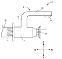
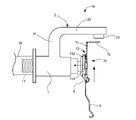
- FIG. 1 is a side view of the hot water supply faucet according to the present embodiment
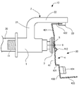
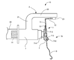
- FIG. 2 is a side view showing a state in which an attachment is attached to the hot water supply faucet of FIG.
- the hot water supply faucet 10 will be described first, and then the attachment 20 attached to the hot water supply faucet 10 will be described.
- the explanation will be given based on the direction shown in FIG.
- the direction perpendicular to the paper surface of FIG. 1 will be described as the left-right direction.
- other drawings will be described according to this direction.
- this direction is a provision for explaining the present embodiment, and the present invention is not limited to this direction.
- Hot water faucet The hot water supply faucet 10 according to the present embodiment is used in a store such as conveyor belt sushi, and is connected to a hot water supply branch pipe 30 branching from a pipe (not shown) through which hot water flows in the store.
- the hot water supply faucet 10 has a tubular faucet main body 1 extending in the front-rear direction and connected to a hot water supply branch pipe 30, an opening / closing mechanism attached to the front end side of the faucet main body 1.
- the faucet main body 1 is provided with a nozzle portion 2 extending upward from the vicinity of the center in the front-rear direction.
- the faucet body 1 is formed in a cylindrical shape, and a male screw 11 for connecting to the hot water supply branch pipe 30 is formed at the rear end portion. Then, hot water is supplied from the hot water supply branch pipe 30 to the faucet main body 1.
- the opening / closing mechanism includes a valve member (not shown) housed inside the faucet main body 1 and a push button 3 for opening / closing the valve member.
- the valve member is arranged in the portion of the faucet body 1 to which the nozzle portion 2 is attached, and when the valve member is in the closed state, hot water is not supplied from the faucet body 1 to the nozzle portion 2 side. When the faucet body 1 is opened, hot water flows from the faucet body 1 to the nozzle portion 2 side.
- the push button 3 is attached to the front end of the faucet body 1. More specifically, the push button 3 is attached so as to be movable by a predetermined length in the front-rear direction by a stopper (not shown). Further, the push button 3 is always urged forward by a spring (not shown). Then, when the push button 3 is pushed backward against this spring, the valve member is opened and hot water flows from the faucet main body 1 to the nozzle portion 2 side. Further, as will be described later, a female screw 31 for attaching the attachment 20 is formed on the front surface of the push button 3. The portion constituting the front portion of the push button 3 on which the female screw 31 is formed is formed in a disk shape.
- the nozzle portion 2 is a member for discharging hot water flowing from the faucet main body 1, and is a tubular first portion 21 extending upward from the faucet main body 1 and a tubular first portion 21 extending forward from the upper end of the first portion 21. It is provided with two sites 22 and is formed in a substantially L shape in a lateral view. However, the connecting portion between the first portion 21 and the second portion 22 is formed in a smooth curved shape in a side view.
- a cylindrical discharge port 23 protrudes slightly downward from the lower surface of the tip of the second portion 22, and hot water is discharged from this discharge port 23. Further, by providing the first portion 21 and the second portion 22, the discharge port 23 is configured to be located above and in front of the push button 3.
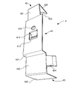
- FIGS. 3 to 5 is a perspective view of the attachment from the front
- FIG. 4 is a perspective view of the attachment from the rear
- FIG. 5A is a perspective view of the washer provided on the attachment from the front
- FIG. 5B is a rear view of the washer provided on the attachment. It is a perspective view seen from.
- the attachment 20 includes an attachment main body 4 formed of a plate material, a countersunk screw 6 for fixing the attachment main body 4 to a hot water supply faucet 10, an attachment main body 4 and a push button 3. It is equipped with a washer 5 arranged between them.
- the attachment main body 4 includes a main body portion 41, a fulcrum portion 42 connected to the upper end of the main body portion 41, and a support portion 43 connected to the lower end of the main body portion 41. These are integrally formed.
- the main body 41 is formed of a rectangular plate in front view, and a rectangular first through hole 411 is formed near the center in the vertical direction.
- a protruding portion 412 extending downward is connected to the upper edge of the first through hole 411.
- the protrusion 412 includes a rectangular upper portion 413 connected to the upper edge of the first through hole 411 and a lower portion 414 connected to the lower end of the upper portion 413.
- the upper portion 413 extends diagonally downward from the upper edge of the first through hole 411 toward the front, and the lower portion 414 extends diagonally downward from the lower end of the upper portion 413 toward the rear. Therefore, the protruding portion 412 having the upper portion 413 and the lower portion 414 is formed so as to project forward in a mountain shape in the side view.
- a circular second through hole 415 is formed above the protrusion 412, and the countersunk screw 6 described above is inserted into the second through hole 415. Therefore, the inner diameter of the second through hole 415 is smaller than the outer diameter of the head of the countersunk screw 6.
- the fulcrum portion 42 includes a rectangular first portion 421 extending upward from the upper end portion of the main body portion 41, and a second portion 422 extending forward from the upper end portion of the first portion 421.
- the first portion 421 is formed in a plate shape having a width slightly narrower than that of the main body portion 41, and extends slightly diagonally toward the rear from the main body portion 41.
- the second portion 422 is formed in a plate shape, and an arc-shaped recess 423 is formed at the front end portion.
- the recess 423 is adapted to engage with the outer peripheral surface of the discharge port 23 provided in the nozzle portion 2 from the rear.
- the support portion 43 includes a step portion 431 extending forward from the lower end of the main body portion 41, an extending portion 432 extending downward from the front end of the step portion 431, and a bottom wall portion 433 extending forward from the lower end of the extending portion 432. And a pair of holding portions 434 extending forward from both side edges of the extending portion 432, and these are integrally formed.
- the extending portion 432 and the bottom wall portion 433 are connected in an L shape in a side view, and as will be described later, when supplying hot water, the bottom portion 61 of the teacup 6 is placed on the bottom wall portion 433, and the teacup 6 is placed. The outer peripheral surface of the bowl is pressed against the extending portion 432.
- the pair of holding portions 434 are obliquely connected to the extending portion 432 so as to be separated from each other toward the front from the extending portion 432. As a result, when the teacup 6 is placed on the bottom wall portion 433, the outer peripheral surface of the teacup 6 is sandwiched by the holding portion 434.
- the material that forms the attachment body 4 is not particularly limited, but can be formed of, for example, a metal or resin material.
- the washer 5 will be described. As described above, the washer 5 is arranged between the attachment main body 4 and the push button 3, but as shown in FIGS. 5A and 5B, a flat surface 51 is formed on the attachment main body 4 side. The flat surface 51 comes into contact with the rear surface of the main body 41 of the attachment main body 4.
- the side in contact with the push button 3 is formed in a mountain shape having an annular top (protrusion) 52 in cross section. That is, it extends radially inward from the outer edge of the washer 5 toward the top 52 and diagonally forward toward the inner edge of the through hole 53 in the radial direction from the top 52.
- the top 52 of the washer 5 is in contact with the front surface of the push button 3.
- the attachment main body 4 is arranged on the lower side of the nozzle portion 2, and the concave portion 423 of the fulcrum portion 42 is engaged with the outer peripheral surface of the discharge port 23 from the rear side.
- the washer 5 placed between the attachment body 4 and the push button 3, insert the countersunk screw 6 into the second through hole 415 from the front, and insert the male screw of the countersunk screw 6 into the female screw on the front of the push button 3. Screw it into 31.
- the countersunk screw 6 is screwed in until a part of the flat surface 51 of the washer 5 touches the rear surface of the attachment main body 4 and the top 52 touches the front surface of the push button 3.
- the attachment 20 is completed.
- the main body portion 41 can be moved. It is arranged so as to extend downward slightly diagonally with respect to the front surface of the push button 3. Therefore, in the initial state, the rear surface of the main body 41 is arranged so as to be in contact with the upper end of the flat surface 51 of the washer 5 (see FIG. 8A).
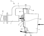
- hot water is supplied as follows. First, as shown in FIG. 6, while placing the bottom portion 61 of the teacup (container) 6 containing the tea bag or powdered tea on the bottom wall portion 433 of the attachment main body 4, the lower end portion of the outer peripheral surface of the teacup 6 is extended. Press against 432. It should be noted that the lower end portion of the outer peripheral surface of the teacup 6 may be simply pressed against the extending portion 432. At this time, since the outer peripheral surface of the teacup 6 is in contact with the protruding portion 412, it is not in contact with the main body portion 41. Further, the outer peripheral surface of the teacup 6 is supported from both sides by a pair of holding portions 434.
- the tip of the fulcrum portion 42 that is, the recess 423 engaging with the discharge port 23 serves as a fulcrum
- the attachment main body 4 rotates backward. ..
- the push button 3 is pushed by the attachment main body 4, and hot water is discharged from the discharge port 23.
- the discharged hot water is accumulated in the teacup 6 arranged below the teacup 6, but when a desired amount of hot water is accumulated in the teacup 6, the pressing of the extending portion 432 by the teacup 6 is released.
- the push-in button 3 is released, and the discharge of hot water from the discharge port 23 is stopped. After that, the teacup 6 is removed from the attachment body 4.
- the fulcrum portion 42 is used as a fulcrum, and the vicinity of the lower end of the attachment main body 4 below the push button 3, that is, the extending portion 432 is pressed by the teacup 6. is doing. At this time, since the push button 3 is pressed near the center of the attachment body 4 in the vertical direction, the push button 3 can be pressed with a weaker force than when the push button 3 is directly pressed.
- the protruding portion 412 is formed on the main body portion 41, it is possible to prevent the outer peripheral surface near the upper opening of the teacup 6, that is, the portion to which the user puts his mouth, from coming into contact with the main body portion 41. Therefore, it is hygienic.
- the main body 41 of the attachment main body 4 is in diagonal contact with the flat surface 51 of the washer 5. That is, the main body portion 41 is in contact with the vicinity of the upper end of the flat surface 51, and a gap is formed between the lower end of the flat surface 51 and the main body portion 41.
- the main body portion 41 comes into contact with the vicinity of the lower end of the flat surface 51, and a gap is formed between the upper end of the flat surface 51 and the main body portion 41.
- the main body 41 and the washer 5 are not in surface contact with each other, but are in contact with each other by point contact or line contact so that the contact points change so as to correspond to the turning of the attachment main body 4. Therefore, even if the attachment body 4 turns, the force can be efficiently transmitted.
- the portion of the washer 5 in contact with the push button 3 is the annular top portion 52, which is in line contact with the push button 3. Further, the top portion 52 has a diameter smaller than the outer diameter of the washer 5. Therefore, the force acting on the washer 5 can be concentrated near the center of the push button 3, and the force for pushing the teacup 6 can be efficiently transmitted to the push button 3. As a result, the force for pressing the push button 3 can be reduced.
- the structure of the washer 5 is not particularly limited, and a normal washer without a top 52, that is, a washer whose both sides in the axial direction are flat surfaces may be used. Further, the washer 5 is not always necessary, and the main body 41 can be directly fixed to the push button 3. Further, the countersunk screw 6 may be other than the fixing tool such as a bolt. Further, the position where the countersunk screw 6 or the like is attached is not particularly limited, and may be other than the push button 3.
- the attachment main body 4 is installed so as to be slightly oblique to the push button 3, but the attachment main body 4 and the front surface of the push button 3 are parallel to each other. 4 may be installed.
- the attachment main body 4 is integrally formed of a plate material, but it can also be formed by combining a plurality of members.
- the support portion 43 is arranged so as to be located in front of the main body portion 41, the support portion 43 may be arranged on an extension of the main body portion 41.
- the configuration of the protruding portion 412 is not particularly limited, and may be configured so that a gap is formed between the attachment main body 4 and the teacup 6.
- the protrusion 412 is not always necessary and may not be provided.
- the sandwiching portion 434 is not always necessary.
- a recess 423 is formed in the fulcrum portion 42 of the attachment main body 4 and attached to the outer peripheral surface of the discharge port 23, but the present invention is not limited to this, and the portion is above the push button 3 and serves as a fulcrum when turning. As long as it is attached to the nozzle portion 2, the attachment position and the attachment method are not particularly limited. Further, the attachment main body 4 is sized so that when it comes into direct or indirect contact with the push button 3, it can be attached to any position of the nozzle portion 2 such as the discharge port 23 so that the fulcrum portion 42 becomes a fulcrum. All you need is.
- the attachment main body 4 can be easily removed from the hot water supply faucet 10 by removing the countersunk screw 6. Therefore, for example, when the attachment main body 4 becomes dirty, it is removed and cleaned. can do. Further, if the attachment body 4 is damaged, it can be easily replaced. Further, the hot water supply faucet 10 can be used with the attachment 20 removed.
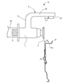
- FIGS. 9 to 12 are side views showing a state in which the attachment is attached to the hot water supply faucet
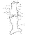
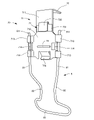
- FIG. 10 is a perspective view of the attachment as viewed from the front
- FIG. 11 is a perspective view of the attachment as viewed from the rear
- FIG. 12 is the attachment and the hot water supply faucet. It is a side view explaining the relationship of the dimension with. Since the hot water supply faucet is the same as that of the first embodiment, the description thereof will be omitted.
- the attachment 70 includes an attachment main body 7 formed of a plate material and a support portion 8 extending from a lower end portion of the attachment main body 7.
- the attachment main body 7 includes a main body portion 71 and a fulcrum portion 72 connected to the upper end of the main body portion 71, and these are integrally formed. Further, on the back surface of the main body 71, a first engaging member 73 that engages with the upper edge of the push button 3 and a protruding member that is arranged below the first engaging portion 73 and can come into contact with the push button 3. 74 is provided.
- the main body portion 71 has a first portion 711 formed in a rectangular shape and a second portion 712 integrally connected to the lower end portion of the first portion 711, and the width of the second portion 712 is wide. It is larger than the first part 711.
- a fulcrum portion 72 is connected to the first portion 711 as described later.
- the upper end portion and the lower end portion thereof are bent rearward in a U shape, and an insertion portion 713 through which the support portion 8 described later is inserted is formed.
- the portions between the vertically arranged insertion portions 713 are bent rearward in a U shape, and the second engaging portion 714 that engages with the outer edge of the push button 3 is formed. Has been done.
- Each second engaging portion 714 projects rearward from the insertion portion 713.
- a rectangular notch 715 is formed at the lower end of the main body 71, and a downwardly extending protrusion 716 is connected to the upper edge of the notch 715.
- the protrusion 716 has the same function as the protrusion 412 of the first embodiment. That is, the protrusion 716 includes a rectangular upper portion 717 connected to the upper edge of the notch 715 and a lower portion 718 connected to the lower end of the upper portion 717.
- the upper portion 717 extends diagonally downward from the upper edge of the notch 715 toward the front, and the lower portion 718 extends diagonally downward from the lower end of the upper portion 717 toward the rear. Therefore, the protruding portion 716 having the upper portion 717 and the lower portion 718 is formed so as to project forward in a mountain shape in the side view.
- the first engaging portion 73 has a plate-shaped first portion 731 fixed to the back surface of the main body portion 71 with an adhesive or the like, and a plate-shaped portion extending downward from the upper end of the first portion 731. It has a second site 732 and.
- the second portion 732 extends diagonally downward from the upper end of the first portion 731 toward the rear, and a gap is formed between the second portion 732 and the first portion 731.
- the first part 731 and the second part 732 are connected so as to be elastically deformable, and when a force is applied forward to the second part 732, the second part 732 approaches the first part 731. It has become like.
- the projecting member 74 is a columnar rod-shaped member extending in the horizontal direction, and is fixed by an adhesive or the like between the first engaging portion 73 and the projecting portion 716 on the back surface of the main body portion 71.
- the fulcrum portion 72 is formed so as to extend forward from the upper end portion of the main body portion 71 so as to be orthogonal to the main body portion 71.
- the fulcrum portion 72 is formed in a plate shape, and an arc-shaped recess 721 is formed at the front end portion.
- the recess 721 is adapted to engage with the outer peripheral surface of the discharge port 23 provided in the nozzle portion 2 from the rear.
- the support portion 8 is a member formed by bending a wire rod, and supports the vicinity of the lower end of the teacup 6 as described later.
- the support portion 8 is composed of a pair of first site 81, a pair of second site 82, and a pair of third site 83.
- the first portion 81 is a linear portion constituting both ends of the support portion 8, and is inserted through the above-mentioned insertion portion 713 and extends downward.
- a retaining portion 811 having a large outer shape is provided at the upper end of the first portion 81, thereby preventing the support portion 8 from detaching downward from the insertion portion 713.
- a second portion 82 is provided at the lower end of each first portion 81.
- Each second site 82 extends forwardly from the first site 81 and diagonally so as to be close to each other, and further extends linearly downward from there.
- a third portion 83 is provided so as to connect the lower ends of both second portions 82 to each other.
- the third portion 83 is formed in an elliptical shape that is long in the horizontal direction, and is formed in an arc shape in a plan view so that both ends thereof project forward. By forming the third portion 83 in an arc shape in this way, it is possible to abut on the outer peripheral surface of the teacup 6.
- the support portion 8 By inserting the first portion 81 into the insertion portion 713 as described above, the support portion 8 can move up and down with respect to the main body portion 71. As a result, the position of the support portion 8 can be adjusted according to the length of the teacup 6 in the vertical direction.
- the dimensional relationship between the hot water supply faucet 10 and the attachment 70 is set as follows.
- the horizontal distance D1 between the front surface of the push button 3 of the hot water supply faucet 10 and the rear end portion of the discharge port 23 is when the main body portion 71 of the attachment 70 is arranged so as to extend in the vertical direction.
- the distance between the rear end of the protruding member 74 and the rear end of the recess 721 of the fulcrum 72 is shorter than the horizontal distance D2.
- the attachment 70 can be attached to the hot water supply faucet 10 by using the urging force of the push button 3 and the first engaging portion 73.
- the distance D1 is shorter than the distance D2, and the first engaging portion 73 engages with the upper edge of the push-in button 3. It prevents the attachment 70 from coming off downward by preventing it from coming off. Further, since the second engaging portion 714 engages with both sides of the outer edge of the push button 3, the attachment 70 is prevented from being displaced horizontally with respect to the push button 3. In this way, the attachment of the attachment 70 is completed.
- the tip of the fulcrum portion 72 that is, the recess 721 that engages with the discharge port 23 serves as a fulcrum, and the attachment 70 turns backward.
- the push button 3 is pushed by the attachment 70, and hot water is discharged from the discharge port 23.
- the discharged hot water is accumulated in the teacup 6 arranged below the teacup 6, but when a desired amount of hot water is accumulated in the teacup 6, the pressing of the support portion 8 by the teacup 6 is released.
- the push-in button 3 is released, and the discharge of hot water from the discharge port 23 is stopped. After that, the teacup 6 is removed from the attachment 70.
- attachment 70 can be attached to the hot water supply faucet 10 while sliding, there is no need to use a tool and the attachment is easy.
- the protruding member 74 can obtain the same effect as the washer of the attachment of the first embodiment. That is, since the protruding member 74 is formed in a rod shape, the force for pressing the attachment 70 through the teacup 6 can be concentrated on the push button 3. Further, since the projecting member 74 is formed in a columnar shape extending in the horizontal direction, the curved surface of the outer peripheral surface thereof comes into contact with the push button 3. Therefore, even if the attachment 70 touches the push button 3 while tilting, the outer peripheral surface of the projecting member 74 always makes line contact with the push button 3, so that the force can be efficiently transmitted to the push button 3.
- the support portion 8 is movably provided with respect to the attachment main body 7, but the support portion 8 may be fixed to the attachment main body 7.
- the shape of the support portion 8 is not particularly limited, and it may be formed of a plate material instead of a wire material.
- the configuration of the first engaging portion 73 and the second engaging portion 714 is not particularly limited, and is not particularly limited as long as it is configured to engage the push button 3. Therefore, it can be appropriately changed according to the shape of the push button.
- the protruding member 74 may have a shape other than the rod shape as described above, and may be a member that comes into contact with the push button 3 in a small area, for example, a member that makes point contact or line contact. However, the protruding member 74 is not essential and may be provided as needed. When the projecting member 74 is not provided, the distance D2 is the distance from the portion of the attachment 70 in contact with the push button 3 to the rear end of the recess 721 of the fulcrum portion 72 in relation to the dimensions shown in FIG. Further, the protruding portion 716 is not essential, and may be provided as needed.
- the present invention is not limited to this, and the attachment 20 is applied to various hot water supply faucets. Can be done.
- the hot water supply faucet to which the attachment according to the present invention is attached has at least a nozzle portion 2 having a discharge port 23 that opens downward, below the discharge port 23, and horizontally behind the discharge port 23. It suffices to have a push button 3 to be arranged, and other configurations are not particularly limited.
Landscapes
- Engineering & Computer Science (AREA)
- General Engineering & Computer Science (AREA)
- Public Health (AREA)
- Health & Medical Sciences (AREA)
- Life Sciences & Earth Sciences (AREA)
- Hydrology & Water Resources (AREA)
- Water Supply & Treatment (AREA)
- Mechanical Engineering (AREA)
- Physics & Mathematics (AREA)
- Thermal Sciences (AREA)
- Chemical & Material Sciences (AREA)
- Combustion & Propulsion (AREA)
- Food Science & Technology (AREA)
- Domestic Plumbing Installations (AREA)
Priority Applications (3)
| Application Number | Priority Date | Filing Date | Title |
|---|---|---|---|
| JP2022565228A JP7709063B2 (ja) | 2020-11-24 | 2021-11-12 | アタッチメント、及びこれを備えた給湯用具 |
| CN202180071734.7A CN116367760B (zh) | 2020-11-24 | 2021-11-12 | 配件以及具备该配件的热水供应用具 |
| US18/038,320 US12116260B2 (en) | 2020-11-24 | 2021-11-12 | Attachment and hot-water supply device provided with the same |
Applications Claiming Priority (4)
| Application Number | Priority Date | Filing Date | Title |
|---|---|---|---|
| JP2020194592 | 2020-11-24 | ||
| JP2020-194592 | 2020-11-24 | ||
| JP2021046688 | 2021-03-19 | ||
| JP2021-046688 | 2021-03-19 |
Publications (1)
| Publication Number | Publication Date |
|---|---|
| WO2022113789A1 true WO2022113789A1 (ja) | 2022-06-02 |
Family
ID=81755970
Family Applications (1)
| Application Number | Title | Priority Date | Filing Date |
|---|---|---|---|
| PCT/JP2021/041806 Ceased WO2022113789A1 (ja) | 2020-11-24 | 2021-11-12 | アタッチメント、及びこれを備えた給湯用具 |
Country Status (5)
| Country | Link |
|---|---|
| US (1) | US12116260B2 (https=) |
| JP (1) | JP7709063B2 (https=) |
| CN (1) | CN116367760B (https=) |
| TW (1) | TWI876100B (https=) |
| WO (1) | WO2022113789A1 (https=) |
Citations (3)
| Publication number | Priority date | Publication date | Assignee | Title |
|---|---|---|---|---|
| JP2942715B2 (ja) * | 1995-04-24 | 1999-08-30 | 株式会社石野製作所 | 給湯水栓 |
| JP2005163458A (ja) * | 2003-12-04 | 2005-06-23 | Haisaabu Ueno:Kk | 給湯水栓 |
| JP2014229595A (ja) * | 2013-05-27 | 2014-12-08 | アイホン株式会社 | ボタン装置 |
Family Cites Families (9)
| Publication number | Priority date | Publication date | Assignee | Title |
|---|---|---|---|---|
| US4974643A (en) * | 1986-01-31 | 1990-12-04 | The Cornelius Company | Method of and apparatus for dispensing beverage into a tilted receptacle with automatic level responsive shut off |
| US6058986A (en) * | 1994-11-17 | 2000-05-09 | Imi Cornelius Inc. | Beverage dispensing control |
| CN2639646Y (zh) * | 2003-08-10 | 2004-09-08 | 张勇涛 | 按钮式防烫水龙头 |
| JP4076528B2 (ja) * | 2004-08-30 | 2008-04-16 | 日立アプライアンス株式会社 | 冷蔵庫扉閉鎖装置 |
| US7644741B2 (en) * | 2006-09-15 | 2010-01-12 | T & S Brass And Bronze Works, Inc. | Glass filler |
| KR20100107150A (ko) * | 2009-03-25 | 2010-10-05 | 웅진코웨이주식회사 | 온수 취출 장치 |
| CN104739241B (zh) * | 2013-12-31 | 2017-05-24 | 沁园集团股份有限公司 | 一种外置加热水壶饮水机的取放机构 |
| CN208211913U (zh) * | 2017-08-21 | 2018-12-11 | Tcl家用电器(中山)有限公司 | 水龙头及饮水机 |
| CN108742156B (zh) * | 2018-04-26 | 2024-02-23 | 上海北工华泰环保科技有限公司 | 一种多功能一体式直饮水机 |
-
2021
- 2021-10-27 TW TW110139829A patent/TWI876100B/zh active
- 2021-11-12 US US18/038,320 patent/US12116260B2/en active Active
- 2021-11-12 WO PCT/JP2021/041806 patent/WO2022113789A1/ja not_active Ceased
- 2021-11-12 JP JP2022565228A patent/JP7709063B2/ja active Active
- 2021-11-12 CN CN202180071734.7A patent/CN116367760B/zh active Active
Patent Citations (3)
| Publication number | Priority date | Publication date | Assignee | Title |
|---|---|---|---|---|
| JP2942715B2 (ja) * | 1995-04-24 | 1999-08-30 | 株式会社石野製作所 | 給湯水栓 |
| JP2005163458A (ja) * | 2003-12-04 | 2005-06-23 | Haisaabu Ueno:Kk | 給湯水栓 |
| JP2014229595A (ja) * | 2013-05-27 | 2014-12-08 | アイホン株式会社 | ボタン装置 |
Also Published As
| Publication number | Publication date |
|---|---|
| CN116367760A (zh) | 2023-06-30 |
| US12116260B2 (en) | 2024-10-15 |
| TWI876100B (zh) | 2025-03-11 |
| US20240002210A1 (en) | 2024-01-04 |
| CN116367760B (zh) | 2026-02-17 |
| JPWO2022113789A1 (https=) | 2022-06-02 |
| JP7709063B2 (ja) | 2025-07-16 |
| TW202228579A (zh) | 2022-08-01 |
Similar Documents
| Publication | Publication Date | Title |
|---|---|---|
| JP5330742B2 (ja) | 詰替えパウチの内容物取出装置 | |
| WO2022113789A1 (ja) | アタッチメント、及びこれを備えた給湯用具 | |
| EP2258955B1 (fr) | Dispositif de pince à écrou, susceptible d'être placé sur le bord d'un support tel qu'un panneau | |
| EP4173530A1 (fr) | Machine a cafe automatique munie d'un dispositif de moussage de lait amovible avec maintien ameliore | |
| FR3040131A1 (fr) | Dispositif a ouverture rapide par pression unique d'un couvercle de toilette | |
| FR2916643A1 (fr) | Absorbeur de gaz carbonique destine a un systeme de reinspiration | |
| FR2510349A1 (fr) | Pots de fleurs ou analogues a accrochage automatique | |
| FR2724958A1 (fr) | Installation de distribution d'eau pour reservoir de chasse de toilettes sanitaires | |
| FR2631995A1 (fr) | Appareil sanitaire constitue par une cuvette de toilette associee a un reservoir de chasse d'eau | |
| EP2005861A1 (fr) | Système de réglage en hauteur d'un dossier d'un siège | |
| FR2920021A1 (fr) | Dispositif de distribution d'un liquide au verre a partir d'une bouteille, en particulier de vin | |
| WO1992021829A1 (fr) | Support avec va-et-vient pour douche masseuse | |
| EP1462581A1 (fr) | Installation sanitaire pour la distribution d'eau en particulier dans une habitation et ensemble de nourrices | |
| FR2492952A1 (fr) | Appareil pour la fixation de supports de tubes de chauffage par le sol, et supports a fixer avec cet appareil | |
| EP0619976A1 (fr) | Dispositif de fixation d'un abattant de WC | |
| FR2538085A1 (fr) | Dispositif de fixation pour le serpentin en matiere synthetique d'une installation de chauffage par le sol | |
| JPWO2022113789A5 (https=) | ||
| FR2726865A1 (fr) | Collier a cheville integree pour la fixation murale, d'un conduit ou tube | |
| FR2526279A1 (fr) | Outil pour fixer un element d'accouplement a une fermeture a glissiere du type non apparent | |
| EP4133975A1 (fr) | Machine de distribution de boissons munie d'une tete de distribution amelioree | |
| FR2773963A1 (fr) | Support d'equipements de bureau de type multimedia | |
| FR3025984A3 (fr) | Recipient cosmetique | |
| EP0889700A1 (fr) | Appareil distributeur de materiaux d'essuyage pouvant etre distribues sous forme pliee ou non pliee | |
| FR2844503A1 (fr) | Accessoire de conditionnement | |
| FR3058035A1 (fr) | Dispositif de lave-mains pour branchement sur un couvercle de reservoir de toilettes. |
Legal Events
| Date | Code | Title | Description |
|---|---|---|---|
| 121 | Ep: the epo has been informed by wipo that ep was designated in this application |
Ref document number: 21897763 Country of ref document: EP Kind code of ref document: A1 |
|
| ENP | Entry into the national phase |
Ref document number: 2022565228 Country of ref document: JP Kind code of ref document: A |
|
| WWE | Wipo information: entry into national phase |
Ref document number: 18038320 Country of ref document: US |
|
| NENP | Non-entry into the national phase |
Ref country code: DE |
|
| 122 | Ep: pct application non-entry in european phase |
Ref document number: 21897763 Country of ref document: EP Kind code of ref document: A1 |