WO2022113290A1 - 保全支援システム、保全支援装置、および保全支援方法 - Google Patents
保全支援システム、保全支援装置、および保全支援方法 Download PDFInfo
- Publication number
- WO2022113290A1 WO2022113290A1 PCT/JP2020/044299 JP2020044299W WO2022113290A1 WO 2022113290 A1 WO2022113290 A1 WO 2022113290A1 JP 2020044299 W JP2020044299 W JP 2020044299W WO 2022113290 A1 WO2022113290 A1 WO 2022113290A1
- Authority
- WO
- WIPO (PCT)
- Prior art keywords
- information
- component
- maintenance
- electrical equipment
- name
- Prior art date
- Legal status (The legal status is an assumption and is not a legal conclusion. Google has not performed a legal analysis and makes no representation as to the accuracy of the status listed.)
- Ceased
Links
Images






Classifications
-
- G—PHYSICS
- G05—CONTROLLING; REGULATING
- G05B—CONTROL OR REGULATING SYSTEMS IN GENERAL; FUNCTIONAL ELEMENTS OF SUCH SYSTEMS; MONITORING OR TESTING ARRANGEMENTS FOR SUCH SYSTEMS OR ELEMENTS
- G05B23/00—Testing or monitoring of control systems or parts thereof
- G05B23/02—Electric testing or monitoring
Definitions
- This disclosure relates to a maintenance support system, a maintenance support device, and a maintenance support method that detect changes in electrical equipment and notify the administrator.
- the present disclosure has been made in view of the above, and an object thereof is to obtain a maintenance support system that can reduce the time and effort when revising the information of electrical equipment.
- the maintenance support system of the present disclosure includes component information including the correspondence between the name of the electrical equipment and each name of the first component arranged in the electrical equipment. It has a storage unit to store.
- the maintenance support system is provided with an input unit that receives maintenance information that records the name of the second component for which maintenance work has been performed, the presence or absence of maintenance work on the second component, or the work content. .. Further, the maintenance support system determines whether or not the first component corresponding to the second component has been changed by the maintenance work based on the maintenance information, and when the first component is changed.
- the maintenance support system related to this disclosure has the effect of reducing the time and effort required to revise the information on electrical equipment.
- FIG. 1 is a diagram showing a configuration example of a power distribution system according to the first embodiment.
- the distribution system includes the electric power company equipment 2 and the electric power consumer equipment 3.
- the electric power company equipment 2 is the equipment of the electric power company
- the electric power consumer equipment 3 is the equipment of the electric power consumer who receives electricity from the electric power company equipment 2.
- the electric power company equipment 2 includes a power plant 5 that generates electricity by thermal power, nuclear power, etc., and a substation 6 that steps down the generated electricity and supplies it to the electric power consumer equipment 3.
- the substation 6 steps down the electricity transmitted from the power plant 5 at a high voltage of, for example, 500,000 V (volt) to, for example, 6600 V, and supplies it to the power consumer equipment 3.
- the electric power consumer equipment 3 is obliged to safely supply electricity to the load equipment 9, and maintenance activities are carried out for the electric equipment based on the safety regulations established by the electric power consumer.
- the electric equipment included in the electric power consumer equipment 3 includes a high-voltage power receiving / transforming equipment 7, a switchboard 8, and a load equipment 9 as constituent elements.
- the electrical equipment manager (hereinafter referred to as the manager) formulates safety regulations, manages maintenance activities, and manages electrical equipment information, which is information on electrical equipment. Maintenance activities are carried out by the manager requesting a maintenance worker and the maintenance worker carrying out daily inspections and repair work.
- the management of the electrical equipment information is performed by the manager requesting the electrical designer, and the electrical designer creates and revise the electrical equipment information such as the wiring diagram and the layout drawing.
- the electrical equipment information may be revised by the administrator.
- the maintenance support device 1 is an HW (HardWare) such as a personal computer, a mobile terminal such as a smartphone, or a server.
- the maintenance support device 1 may be a combination of at least two of a personal computer, a mobile terminal, and a server.
- the distribution system of the first embodiment detects the change of the electric facility based on the maintenance information for the electric facility of the electric power consumer facility 3, and notifies the manager of the request for revision of the electric facility information which is the information of the electric facility. do.
- Maintenance information is maintenance information for electrical equipment and is created by maintenance workers. Details of the maintenance information will be described later.
- the input unit 11 and the equipment information database 16 may be arranged outside the maintenance support device 1.
- the determination unit 12, the notification creation unit 13, the display control unit 14, and the display unit 15 shown in FIG. 2 are components of the maintenance support device 1.
- a maintenance support system is composed of a maintenance support device 1 including a determination unit 12, a notification creation unit 13, a display control unit 14, and a display unit 15, an input unit 11, and an equipment information database 16.
- the input unit 11 includes, for example, a mouse, a keyboard, and the like.
- the input unit 11 may be a touch pad.
- the display unit 15 is, for example, a liquid crystal display, an organic EL (ElectroLuminescence) display, or the like.
- An example of the display unit 15 is a display screen of a mobile terminal such as a smartphone.
- the maintenance information 201 includes the work date, the name of the work target (hereinafter, may be referred to as the work target name), the work content, and the revision check column.
- the work target is a component included in the electrical equipment to be maintained, and is a component or the like for which maintenance work has actually been performed.
- the work day is the date and time when the maintenance work was carried out
- the work target name is the name of the component part that was the target of the maintenance work.
- the work content is information indicating the content of maintenance work
- the revision check column is revision information indicating whether or not the electrical equipment information needs to be revised. If a check is entered in the revision check column, it indicates that the electrical equipment information needs to be revised.
- An example of the work target name is the switchboard DA
- an example of the work content is the work of increasing the number of branches from two circuits to three circuits in the circuit expansion work.
- maintenance information 201 may include information on work performed regularly such as weekly inspection and monthly inspection, and information on work performed irregularly such as repair work.
- the equipment information database 16 stores electrical equipment information 100, which is information about electrical equipment, load information 101, which is information about load equipment 9, and component component information 102, which is information about parts constituting the load equipment 9. There is.
- electrical equipment information 100 which is information about electrical equipment
- load information 101 which is information about load equipment 9
- component component information 102 which is information about parts constituting the load equipment 9.
- FIG. 4 is a diagram showing an example of electrical equipment information stored in the maintenance support device according to the first embodiment.
- the electrical equipment information 100 is created by the contractor when the electrical equipment is constructed.
- the electrical equipment information 100 is obtained by the administrator from the contractor and stored in the equipment information database 16 in advance.
- the electrical equipment information 100 may include information on the creation date when the electrical equipment information 100 was created, the name of the electrical equipment (hereinafter, may be referred to as an electrical equipment name), and the name of a component (hereinafter, may be referred to as a component name). ), Information on the specifications or product names corresponding to the component names, and wiring diagrams showing the wiring relationships of the components.
- An example of the electrical equipment name registered in the electrical equipment information 100 is the electrical equipment in Building P.
- Examples of component names registered in the electrical equipment information 100 are high-voltage power receiving / transforming equipment H1, switchboard DA, DB, DC, high-voltage cable Ca, low-voltage cable Cb, air conditioners A1, A2, office equipment O1, O2, and pumps. be.
- FIG. 6 is a diagram showing an example of equipment load component component information stored in the maintenance support device according to the first embodiment.
- the component information 102 is data created by the administrator based on the electrical equipment information 100 and the load information 101, and is registered in advance in the equipment information database 16.
- the component information 102 includes the names of the electrical equipment included in the electrical equipment information 100, the names of the component parts of the electrical equipment included in the electrical equipment information 100, and the names of the load equipment 9 included in the load information 101. Contains information indicating the correspondence of.
- the component information 102 which is component information, includes connection information which is information on the connection relationship between the electrical equipment and the component.
- connection information which is information on the connection relationship between the electrical equipment and the component.
- FIG. 6 it is shown that the high-voltage power receiving / transforming equipment H1, the switchboard DA, DB, DC, the high-voltage cable Ca, and the low-voltage cable Cb, which are components, are connected to the electric facility in Building P, which is an electric facility. Shows. Further, it is shown that the air conditioners A1 and A2 are connected to the switchboard DA, the office equipment O1 and O2 are connected to the switchboard DB, and the pump is connected to the switchboard DC.
- the determination unit 12 determines whether or not the electrical equipment information 100 needs to be revised using the maintenance information 201 input to the input unit 11. Specifically, the determination unit 12 detects whether or not the revision check column included in the maintenance information 201 is checked, and if it detects that there is a check, it determines that revision is necessary. When a plurality of electric facilities are registered in the component information 102, the determination unit 12 determines whether or not the electric facility information 100 needs to be revised for the plurality of electric facilities.
- the determination unit 12 identifies the changed electrical equipment based on the maintenance information 201 and the component information 102. Specifically, the determination unit 12 extracts the work target name (in the case of FIG. 3, the switchboard DA) from the maintenance information 201, and sets the electrical equipment including the extracted work target name as the electrical equipment to be revised. do.
- the work target name in the case of FIG. 3, the switchboard DA
- the determination unit 12 searches for the component name that matches the work target name among the component names included in the component information 102, and the electrical equipment name to which the component name that matches the work target name belongs is to be revised. Set to the electrical equipment name.
- the revision target is the name of the electrical equipment included in the notification content (notification content 121 described later) when notifying the administrator that the electrical equipment has been revised. That is, the name of the electrical equipment set as the subject of revision is the name of the electrical equipment of the electrical equipment that has been changed by the maintenance work.
- the determination unit 12 sends the set name of the electrical equipment to be revised and the maintenance information 201 to the notification creation unit 13.
- the notification creation unit 13 receives the name of the electrical equipment to be revised and the maintenance information 201 from the determination unit 12.
- the notification creation unit 13 creates the notification content 121 based on the electrical equipment name and the maintenance information 201.
- the notification content 121 is information for notifying that the electrical equipment information 100 needs to be revised.
- the notification creation unit 13 sends the created notification content 121 to the display control unit 14.
- the display control unit 14 receives the notification content 121 from the notification creation unit 13, and causes the display unit 15 to display the notification screen 120, which will be described later, showing the notification content 121.
- the revision notification for the electrical equipment information 100 is a process of notifying the manager that the electrical equipment information 100 needs to be revised. By revising the electrical equipment information 100 corresponding to the electrical equipment name included in the revision notification, the manager matches the components after the maintenance work with the components included in the electrical equipment information 100.
- the drawing or the like related to the electric equipment information 100 is paper
- the administrator searches for and revise the drawing or the like related to the electric equipment information 100 by referring to the notification screen 120 displayed on the display unit 15.
- the notification content 121 includes a link for calling the digitized drawings and the like. As a result, the administrator can search for necessary drawings and the like simply by clicking the link.
- FIG. 7 is a diagram for explaining the content of the notification displayed on the notification screen by the maintenance support device according to the first embodiment.
- the display unit 15 displays the notification screen 120 showing the notification content 121 according to the instruction from the display control unit 14.
- the notification content 121 includes a message indicating that information such as the electrical equipment information 100 needs to be revised, for example, an "information revision notification". Further, the notification content 121 includes the name of the electric facility to be revised, the reason why the electric facility information 100 needs to be revised, the record of the maintenance work referred to by the manager, and the like.
- the name of the electrical equipment to be revised is the name of the electrical equipment set by the determination unit 12 based on the component information 102.
- the notification content 121 in FIG. 7 shows the case where the name of the electrical equipment to be revised is the electrical equipment in Building P. Further, the notification content 121 in FIG. 7 shows the case where the reason why the electrical equipment information 100 needs to be revised is the implementation of maintenance work.
- the reference maintenance work record which is a record of maintenance work referred to by the administrator, includes the work date of the maintenance work, the work target name of the component part for which the maintenance work was performed, the work content of the maintenance work, and the like.
- the work target name is the name of the component component set by the determination unit 12 based on the component component information 102.
- the work target name in the reference maintenance work record is the switchboard DA.
- the reference maintenance work record is created based on the maintenance information 201.
- FIG. 8 is a flowchart showing a processing procedure of revision notification processing of electrical equipment information by the maintenance support device according to the first embodiment.
- Maintenance information 201 is input to the input unit 11 by the maintenance worker who has performed the maintenance work.
- the input unit 11 receives the maintenance information 201 (step S10).
- the determination unit 12 extracts the work target name from the maintenance information 201 determined to need to be revised. Then, the determination unit 12 extracts the component corresponding to the work target name from the component information 102 by comparing the work target name with the component information 102. The determination unit 12 sets the name of the electrical equipment including the extracted components as a revision target (step S12).
- the determination unit 12 selects the electric equipment in the P building, which is the name of the electric equipment including the distribution board DA, from the component information 102 and sets the revision target. ..
- the determination unit 12 sends the set name of the electrical equipment to be revised and the maintenance information 201 to the notification creation unit 13.
- the notification creation unit 13 receives the name of the electrical equipment to be revised and the maintenance information 201 from the determination unit 12, and creates, for example, the notification content 121 shown in FIG. 7 based on the name of the electrical equipment and the maintenance information 201 (. Step S13).
- the maintenance support device 1 determines whether or not the electrical equipment information 100 needs to be revised based on the maintenance information 201 and the component information 102, so that the electrical equipment information 100 and the load information 101 are used. , Not always necessary.
- FIG. 9 is a diagram showing an example of the hardware configuration of the maintenance support device according to the first embodiment.
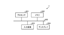
- the maintenance support device 1 can be realized by a processor 601, a memory 602, an input device 603, and a display 604.
- the processor 601 is an example of a processing circuit.
- An example of the processor 601 is a CPU (central processing unit, processing unit, arithmetic unit, microprocessor, microprocessor, DSP (Digital Signal Processor)) or system LSI (Large Scale Integration).
- Examples of the memory 602 are RAM (Random Access Memory) and ROM (Read Only Memory).
- the processor 601, the memory 602, the input device 603, and the display 604 can send and receive information to and from each other by, for example, the bus 605.
- the input unit 11 is realized by the input device 603.
- the display unit 15 is realized by the display 604.
- the equipment information database 16 is realized by the memory 602.
- the maintenance support device 1 is realized by the processor 601 reading and executing a maintenance support program that can be executed by a computer for executing the operation of the maintenance support device 1 stored in the memory 602. It can be said that the maintenance support program, which is a program for executing the operation of the maintenance support device 1, causes the computer to execute the procedure or method of the maintenance support device 1.
- the input device 603 receives the maintenance information 201 and sends it to the processor 601.
- the memory 602 stores the maintenance support program, the electrical equipment information 100, the load information 101, and the component information 102.
- the processor 601 executes the functions of the determination unit 12, the notification creation unit 13, and the display control unit 14 by reading and executing the maintenance support program stored in the memory 602. That is, the maintenance support program executed by the maintenance support device 1 has a modular configuration including a determination unit 12, a notification creation unit 13, and a display control unit 14, which are loaded on the main storage device, and these are loaded. Generated on main memory.
- the maintenance support program is a file in an installable format or an executable format, and may be stored in a computer-readable storage medium and provided as a computer program product. Further, the maintenance support program may be provided to the maintenance support device 1 via a network such as the Internet. It should be noted that some of the functions of the maintenance support device 1 may be realized by dedicated hardware such as a dedicated circuit, and some may be realized by software or firmware.
- the maintenance support device 1 includes a determination unit 12 and a notification creation unit 13.
- the determination unit 12 determines whether or not it is necessary to revise the electrical equipment information 100 relating to the electrical equipment based on the maintenance information 201.
- the determination unit 12 extracts the work target name from the maintenance information 201 and sets it as the work target name to be revised.
- the determination unit 12 compares the work target name with the component information 102, and determines the name of the electrical equipment to be revised.
- the notification creation unit 13 creates a notification content 121 in which the name of the electrical equipment to be revised and the name of the work target are described, based on the name of the electrical equipment and the component information 102.
- the display control unit 14 receives the notification content 121 from the notification creation unit 13, and causes the display unit 15 to display the notification screen 120 showing the notification content 121.
- the maintenance support device 1 can present the electric equipment information 100 that needs to be revised according to the maintenance work to the manager of the electric equipment.
- the maintenance support device 1 of the second embodiment determines whether or not the electrical equipment information 100 and the load information 101 need to be revised based on the maintenance information 201, and based on the determination result, the electrical equipment information 100 and the load information Notify the revision of 101.
- the revision notification of the electrical equipment information 100 and the load information 101 is a process of notifying the manager that the electrical equipment information 100 and the load information 101 need to be revised.
- the configuration of the maintenance support device 1 of the second embodiment is the same as the configuration of the maintenance support device 1 of the first embodiment, the description thereof will be omitted.
- the maintenance support device 1 determines whether or not the electric equipment information 100 and the load information 101 need to be revised based on the maintenance information 201, and if the revision is necessary, the electric equipment information 100 And a notification for requesting revision of the load information 101 is given.
- FIG. 10 is a diagram showing an example of maintenance information input to the maintenance support device according to the second embodiment.
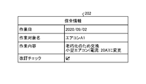
- the maintenance information 202 includes a work date, a work target name, a work content, and a revision check column.
- the maintenance information 202 of FIG. 10 shows a case where the work target name is the air conditioner A1, the work content is replacement due to aging, and the work is changed to a small air conditioner (current 20A).
- the load equipment 9 is changed due to the replacement of the air conditioner A1, and the load information 101 needs to be revised in addition to the electrical equipment information 100.
- the maintenance support device 1 of the second embodiment executes the revision notification process to the administrator by the same processing procedure as the maintenance support device 1 of the first embodiment described with reference to FIG.
- the input unit 11 receives the maintenance information 202 (step S10).
- the determination unit 12 determines whether or not the revision check column included in the maintenance information 202 is checked (step S11). If there is a check (step S11, Yes), the determination unit 12 determines that revision is necessary. If there is no check (step S11, No), the determination unit 12 determines that revision is not necessary, and ends the notification process.
- the determination unit 12 extracts the work target name from the maintenance information 202 determined to need to be revised. Then, the determination unit 12 extracts the component corresponding to the work target name from the component information 102 by comparing the work target name with the component information 102. Since the work target name here is the name of the load equipment 9 among the component parts, the determination unit 12 extracts the load equipment 9 corresponding to the work target name from the component component information 102. Further, the determination unit 12 extracts the name of the electrical equipment to which the extracted load equipment 9 belongs from the component information 102.
- the determination unit 12 sets the extracted load equipment 9 and the name of the electrical equipment as revision targets (step S12).
- the notification creation unit 13 receives the name of the electrical equipment and the load equipment to be revised and the maintenance information 202 from the determination unit 12, and creates, for example, the notification content 123 described later (step S13).
- the display control unit 14 receives the notification content 123 from the notification creation unit 13 and displays the notification screen 122, which will be described later, on the display unit 15 (step S14).
- FIG. 11 is a diagram for explaining the content of the notification displayed on the notification screen by the maintenance support device according to the second embodiment.
- the same information as the information included in the notification content 121 described with reference to FIG. 7 will be omitted.
- the display unit 15 displays the notification screen 122 showing the notification content 123 according to the instruction from the display control unit 14.
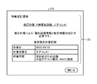
- the notification content 123 includes a message indicating that the electrical equipment information 100 and the load information 101 need to be revised.
- the notification content 123 includes the name of the electrical equipment to be revised, the name of the load equipment to be revised, the reason why the electrical equipment information 100 and the load information 101 need to be revised, the reference maintenance work record referred to by the administrator, and the like. ing.
- the reference maintenance work record which is a record of maintenance work referred to by the administrator, includes the work date of the maintenance work, the name of the work target for which the maintenance work was performed, the work content of the maintenance work, and the like.
- the work target name is a work target name set by the determination unit 12 based on the component information 102.
- the work target name of the reference maintenance work record is the air conditioner A1.
- the maintenance support device 1 determines whether or not the electrical equipment information 100 needs to be revised based on the maintenance information 202 and the component information 102, the electrical equipment information 100 and the load information 101 are used. , Not always necessary.
- the maintenance support device 1 includes a determination unit 12 and a notification creation unit 13.
- the determination unit 12 determines whether or not the electrical equipment information 100 and the load information 101 need to be revised based on the maintenance information 202.
- the determination unit 12 extracts the work target name from the maintenance information 202 and sets it as the work target name to be revised.
- the determination unit 12 compares the work target name with the component information 102, and determines the load equipment name and the electrical equipment name to be revised.
- the notification creation unit 13 creates the notification content 123 based on the load equipment name, the electrical equipment name, and the component information 102.
- the display control unit 14 receives the notification content 123 from the notification creation unit 13, and causes the display unit 15 to display the notification screen 122 showing the notification content 123.
- the maintenance support device 1 can present the electric equipment information 100 and the load information 101 that need to be revised according to the maintenance work to the electric equipment manager.
- Embodiment 3 Next, the third embodiment will be described with reference to FIGS. 12 to 15.
- the maintenance support device of the third embodiment needs to revise the electrical equipment information 100 by comparing the wiring diagram written in the maintenance information by the maintenance worker with the wiring diagram included in the electrical equipment information 100. Judge whether or not.
- FIG. 12 is a diagram showing a configuration example of the maintenance support device according to the third embodiment.
- the components that achieve the same functions as the maintenance support device 1 of the first embodiment shown in FIG. 2 are designated by the same reference numerals, and duplicate description will be omitted.
- the maintenance support device 1A uses the wiring diagram included in the maintenance information to determine whether or not the electrical equipment information 100 needs to be revised, and if it is determined that the revision is necessary, the revision is made. It differs from the maintenance support device 1 according to the first embodiment in that it gives a notification.
- the maintenance support device 1A gives a revision notification when the wiring diagram included in the maintenance information is different from the wiring diagram included in the electrical equipment information 100.
- the maintenance support device 1A includes an input unit 11, an equipment information database 16, a determination unit 12, a notification creation unit 13, a display control unit 14, a display unit 15, and an acquisition unit 17. ,
- the comparison unit 18 is provided.
- the equipment information database 16 included in the maintenance support device 1A stores the same information as the equipment information database 16 included in the maintenance support device 1.
- the maintenance information 203 includes a work date, a work target name, a work content, and a wiring diagram.
- the wiring diagram included in the electrical equipment information 100 is the first wiring diagram
- the wiring diagram included in the maintenance information 203 is the second wiring diagram.
- the wiring diagram included in the maintenance information 203 includes, for example, the input information 110 input by handwriting or the like by the maintenance worker during the maintenance work.
- the input information 110 in the maintenance information 203 shown in FIG. 13 is the air conditioner A3.
- the acquisition unit 17 acquires the electrical equipment information 100 from the equipment information database 16.
- the comparison unit 18 receives the maintenance information 203 and the electrical equipment information 100 from the acquisition unit 17, and compares the wiring diagram included in the maintenance information 203 with the wiring diagram included in the electrical equipment information 100. At this time, the comparison unit 18 reads out the wiring diagram of the maintenance information 203 and the wiring diagram of the electrical equipment information 100 as PDF (Portable Document Format) data, and reads the PDF data as PDF difference extraction software (for example, Acrobat (registered trademark)). ). The comparison unit 18 detects the difference in the wiring diagram by executing the comparison processing of the wiring diagram using the PDF difference extraction software.
- PDF Portable Document Format
- the comparison unit 18 determines the presence / absence of the input information 110 input in the maintenance work based on the comparison processing result of the wiring diagram.
- the comparison unit 18 sends information indicating the difference in the wiring diagram to the determination unit 12 as the wiring diagram difference information.
- the determination unit 12 receives the wiring diagram difference information. The determination unit 12 determines whether or not it is necessary to revise the electrical equipment information 100 based on the wiring diagram difference information. When the work target name extracted from the maintenance information 203 matches the load equipment 9 included in the component information 102, the determination unit 12 determines the electrical equipment information 100 and the load information 101 based on the wiring diagram difference information. Determine if it needs to be revised.
- the determination unit 12 determines that the electrical equipment information 100 needs to be revised.
- the determination unit 12 identifies the electrical equipment information 100 that needs to be revised based on the wiring diagram difference information.
- FIG. 14 is a diagram for explaining the content of the notification displayed on the notification screen by the maintenance support device according to the third embodiment.
- the same information as the information included in the notification content 121 described with reference to FIG. 7 will be omitted.
- the notification content 125 includes a message indicating that the information on the electrical equipment such as the electrical equipment information 100 needs to be revised.
- the notification content 125 includes the name of the electrical equipment to be revised, the reason why the electrical equipment information 100 needs to be revised, the reference maintenance work record referred to by the administrator, and the like.
- the notification content 125 includes the same wiring diagram as the wiring diagram of the latest maintenance information 203. That is, when the wiring diagram in the maintenance information 203 contains the input information 110 input in the maintenance work, the notification content 125 includes the wiring diagram in which the input information 110 is described.
- the display unit 15 displays the notification screen 124 showing the notification content 125 in a manner capable of identifying which information the input information 110 is among the information included in the notification content 125.
- Maintenance information 203 is input to the input unit 11 by the maintenance worker who has performed the maintenance work.
- the input unit 11 receives the maintenance information 203 (step S10).
- the acquisition unit 17 receives the maintenance information 203 from the input unit 11 and extracts the work target name included in the maintenance information 203. Further, the acquisition unit 17 extracts components matching the work target name from the component information 102. Then, the acquisition unit 17 acquires the electrical equipment information 100 corresponding to the extracted components from the equipment information database 16 (step S21).
- the comparison unit 18 receives the maintenance information 203 and the electrical equipment information 100 from the acquisition unit 17, and extracts and compares the wiring diagram included in the maintenance information 203 and the wiring diagram included in the electrical equipment information 100 (step S22). ).
- the comparison unit 18 sends the wiring diagram difference information indicating the difference in the wiring diagram to the determination unit 12.
- the determination unit 12 determines whether or not there is a difference in the wiring diagram based on the wiring diagram difference information (step S23). That is, the determination unit 12 determines whether or not the electrical equipment information 100 needs to be revised.
- step S23 If there is a difference in the wiring diagram (step S23, Yes), the determination unit 12 determines that the electrical equipment information 100 needs to be revised. When it is necessary to revise the electrical equipment information 100, the maintenance support device 1A executes the processes of steps S12 to S14 described in the first to third embodiments.
- the notification creation unit 13 receives the name of the electrical equipment to be revised and the maintenance information 203 from the determination unit 12, and creates, for example, the notification content 125 shown in FIG. 14 (step S13).
- the display control unit 14 receives the notification content 125 from the notification creation unit 13 and displays the notification screen 124 on the display unit 15 (step S14). If there is no difference in the wiring diagram (step S23, No), the determination unit 12 determines that there is no need for revision, and ends the notification process.
- the maintenance support device 1A determines whether or not the electrical equipment information 100 needs to be revised based on the maintenance information 203, the component component information 102, and the electrical equipment information 100. Therefore, the load information 101. Is not always necessary.
- the maintenance support device 1A uses the load information 101 when the maintenance target is a component.
- the maintenance support device 1A includes an acquisition unit 17, a comparison unit 18, and a determination unit 12.
- the acquisition unit 17 acquires the wiring diagram of the maintenance information 203 changed in the maintenance work and the wiring diagram of the electrical equipment information 100 registered in the equipment information database 16.
- the comparison unit 18 compares the wiring diagram of the maintenance information 203 with the wiring diagram of the electrical equipment information 100, and extracts the difference in the wiring diagram. If there is a difference in the wiring diagram, the determination unit 12 determines that the electrical equipment information 100 needs to be revised. As a result, the maintenance support device 1A can present the electrical equipment information 100 that needs to be revised to the manager without having the maintenance worker input the revision check in the revision check column.
- the equipment input as the input information 110 is the load equipment 9 such as the air conditioner A1
- the maintenance support device 1A needs to be revised without having the maintenance worker input the revision check in the revision check column.
- Electrical equipment information 100 and load information 101 can be presented to the manager.
- Embodiment 4 Next, the fourth embodiment will be described with reference to FIGS. 16 to 20.
- the maintenance support device of the fourth embodiment determines whether or not the electric equipment information 100 needs to be revised based on the image of the work target equipment which is the work target electric equipment which is the maintenance target equipment.
- FIG. 16 is a diagram showing a configuration example of the maintenance support device according to the fourth embodiment.
- components that achieve the same functions as the maintenance support device 1 of the first embodiment shown in FIG. 2 are designated by the same reference numerals, and duplicate description will be omitted.
- the maintenance support device 1B extracts character information indicating the names of components and the like from the maintenance information including the image of the work target equipment.
- the maintenance support device 1B uses the extracted character information to determine whether or not the electrical equipment information 100 needs to be revised, and if it is determined that the revision is necessary, the maintenance support device 1B gives a revision notification. It is different from the maintenance support device 1 related to 1.
- the maintenance support device 1B notifies the revision of the electrical equipment information 100.
- the maintenance support device 1B includes an input unit 11, an equipment information database 16, a determination unit 12, a notification creation unit 13, a display control unit 14, and a display unit 15. Further, the maintenance support device 1B includes an image pickup unit 19 and an image analysis unit 20.
- the equipment information database 16 included in the maintenance support device 1B stores the same information as the equipment information database 16 included in the maintenance support device 1.
- An example of the image pickup unit 19 is a camera that captures a photograph that is an image.
- the image pickup unit 19 may be a digital camera or a camera included in a mobile terminal such as a smartphone.
- the image pickup unit 19 generates an image of the work target equipment and sends it to the input unit 11.
- the image of the work target equipment sent from the image pickup unit 19 is input to the input unit 11 of the maintenance support device 1B. Further, maintenance information is input to the input unit 11 by the maintenance worker who has performed the maintenance work. This maintenance information is information in which the wiring diagram is removed from the maintenance information 203 described with reference to FIG. 13 of the third embodiment.
- the input unit 11 receives maintenance information from the maintenance worker. The input unit 11 attaches an image captured by the image pickup unit 19 to the maintenance information input by the maintenance worker to generate maintenance information 204, which will be described later, including the image.
- An image may be attached to the maintenance information 204 input by the maintenance worker.
- the maintenance worker attaches an image to the maintenance information 204.
- FIG. 17 is a diagram showing an example of maintenance information generated by the input unit of the maintenance support device according to the fourth embodiment.
- the maintenance information 204 includes a work date, a work target name, a work content, and an image of the work target equipment captured by the imaging unit 19.
- FIG. 17 shows a case where the work target is the switchboard DA, and the image pickup unit 19 captures an image of the work target equipment including the switchboard DA.
- the image analysis unit 20 receives the maintenance information 204 from the input unit 11 and analyzes the image captured by the image pickup unit 19. Character information indicating the name of the component is attached to the component included in the work target equipment in advance using a label writer such as Tepla (registered trademark). Therefore, the image captured by the image pickup unit 19 includes a label indicating character information.
- the image analysis unit 20 reads the character information contained in the image using a character recognition application (for example, Google Lens (registered trademark)) for the image including the label indicating the character information, and converts it into text data.
- a character recognition application for example, Google Lens (registered trademark)
- Google Lens registered trademark
- the determination unit 12 receives the text data extracted by the image analysis unit 20 by analyzing the image included in the maintenance information 204 from the image analysis unit 20 together with the maintenance information 204. Further, the determination unit 12 acquires the component information 102 from the equipment information database 16. The determination unit 12 compares the text data with the component information 102, and determines whether or not the electrical equipment information 100 needs to be revised.
- the notification creation unit 13, the display control unit 14, and the display unit 15 included in the maintenance support device 1B have the same functions as the notification creation unit 13, the display control unit 14, and the display unit 15 included in the maintenance support device 1. And execute the same process.
- FIG. 18 is a diagram for explaining the content of the notification displayed on the notification screen by the maintenance support device according to the fourth embodiment.
- the same information as the information included in the notification content 121 described with reference to FIG. 7 will be omitted.
- the display unit 15 displays the notification screen 126 showing the notification content 127 according to the instruction from the display control unit 14.
- the notification content 127 includes a message indicating that the information on the electrical equipment such as the electrical equipment information 100 needs to be revised.
- the notification content 127 includes the name of the electrical equipment to be revised, the reason why the electrical equipment information 100 needs to be revised, the reference maintenance work record referred to by the administrator, and the like. Further, the notification content 127 includes an image of the work target equipment captured by the image pickup unit 19.
- FIG. 19 is a flowchart showing a processing procedure of revision notification processing of electrical equipment information by the maintenance support device according to the fourth embodiment.
- the image pickup unit 19 of the maintenance support device 1B captures an image of the work target equipment for which maintenance work has been performed (step S31).
- the image of the work target equipment sent from the imaging unit 19 is input to the input unit 11.
- the maintenance worker who performed the maintenance work inputs the maintenance information before attaching the image to the input unit 11.
- the input unit 11 receives the maintenance information before the image is attached from the maintenance worker (step S10).
- the input unit 11 attaches an image captured by the image pickup unit 19 to the maintenance information input by the maintenance worker, thereby generating maintenance information 204 including the image.
- the image analysis unit 20 receives the maintenance information 204 from the input unit 11 and analyzes the image attached to the maintenance information 204 (step S32).
- the image analysis unit 20 reads characters included in the image using a character recognition application for an image including a label indicating character information, and converts the image into text data.
- the determination unit 12 receives the maintenance information 204 from the image analysis unit 20. Further, the determination unit 12 receives the text data extracted by the image analysis unit 20 by analyzing the image from the image analysis unit 20. Further, the determination unit 12 acquires the component information 102 from the equipment information database 16. The determination unit 12 compares the text data with the component information 102. The determination unit 12 compares the component indicated by the text data with the component included in the component information 102.
- the determination unit 12 determines whether or not there is a difference between the components shown in the text data and the components included in the component information 102 (step S33). That is, the determination unit 12 determines whether or not the electrical equipment information 100 needs to be revised.
- step S33 If there is a difference in the components (step S33, Yes), the determination unit 12 determines that the electrical equipment information 100 needs to be revised. If there is a difference in the load equipment 9 among the components, the determination unit 12 determines that the electrical equipment information 100 and the load information 101 need to be revised. After that, the maintenance support device 1B executes the processes of steps S12 to S14 described in the first and second embodiments.
- the maintenance support device 1B determines whether or not the electrical equipment information 100 needs to be revised based on the maintenance information 204, the component component information 102, and the electrical equipment information 100. Therefore, the load information 101. Is not always necessary.
- the maintenance support device 1B uses the load information 101 when the maintenance target is a component.
- FIG. 20 is a diagram showing an example of the hardware configuration of the maintenance support device according to the fourth embodiment.
- components that achieve the same functions as the hardware configuration of the maintenance support device 1 of the first embodiment shown in FIG. 9 are designated by the same reference numerals, and duplicate description is omitted. do.
- the processor 601 of the maintenance support device 1B executes the functions of the image analysis unit 20, the determination unit 12, the notification creation unit 13, and the display control unit 14 by reading and executing the maintenance support program stored in the memory 602. .
- the maintenance support program executed by the maintenance support device 1B has a modular configuration including an image analysis unit 20, a determination unit 12, a notification creation unit 13, and a display control unit 14, and these are on the main storage device. Loaded and these are generated on main storage.
- the maintenance support device 1B includes an image pickup unit 19, an image analysis unit 20, and a determination unit 12.
- the image pickup unit 19 acquires an image of the work target equipment.
- the image analysis unit 20 reads characters indicating the names of the component parts from the image and converts them into text data.
- the determination unit 12 compares the component indicated by the text data with the component included in the component information 102, and determines that the electrical equipment information 100 needs to be revised if there is a difference in the component. As a result, the maintenance support device 1B can present the electrical equipment information 100 that needs to be revised to the manager without having the maintenance worker input the revision check in the revision check column.
- Embodiment 5 Next, the fifth embodiment will be described with reference to FIGS. 21 to 24.
- the maintenance support device of the fifth embodiment determines whether or not it is necessary to confirm that the electric equipment has been changed based on the revised electric equipment information and the electric equipment information 100 before the revision.
- the maintenance support device of the fifth embodiment creates and outputs a notification content indicating that the change confirmation of the electric equipment is necessary.
- FIG. 21 is a diagram showing a configuration example of the maintenance support device according to the fifth embodiment.
- the components that achieve the same functions as the maintenance support device 1A of the third embodiment shown in FIG. 12 are designated by the same reference numerals, and duplicate description will be omitted.
- the maintenance support device 1C includes an input unit 11, an equipment information database 16, a determination unit 12, a notification creation unit 13, a display control unit 14, a display unit 15, and an acquisition unit 17. , A comparison unit 18 and an information updating unit 21 are provided.
- the electrical equipment information 103 revised by the administrator is input to the input unit 11.
- the input unit 11 receives the electrical equipment information 103 and sends it to the information update unit 21.
- FIG. 22 is a diagram showing an example of revised electrical equipment information input to the input unit of the maintenance support device according to the fifth embodiment.
- the same information as the information included in the electrical equipment information 100 described with reference to FIG. 4 will not be duplicated.
- the air conditioner A3 with the component name is added, the number of branch circuits of the switchboard DA is changed from 2 circuits to 3 circuits, and the wiring diagram shows. Air conditioner A3 has been added.
- the acquisition unit 17 receives the revised electrical equipment information 103 from the information updating unit 21, and acquires the unrevised electrical equipment information 100 from the equipment information database 16.
- the acquisition unit 17 sends the acquired electrical equipment information 100 and electrical equipment information 103 to the comparison unit 18.
- the comparison unit 18 compares the electric equipment information 100, which is the electric equipment information before the revision, with the electric equipment information 103, which is the electric equipment information after the revision, and detects the difference between the electric equipment information 100 and 103.
- the comparison unit 18 here detects the difference in the wiring diagram by the same processing as the method described in the third embodiment. That is, the comparison unit 18 detects the difference between the wiring diagram included in the electrical equipment information 100 before the revision and the wiring diagram included in the electrical equipment information 103 after the revision.
- the comparison unit 18 sends information indicating the difference between the electrical equipment information 100 and 103 to the determination unit 12 as revised difference information.
- the determination unit 12 receives the revised difference information.
- the determination unit 12 determines whether or not there is a difference in the electrical equipment information 100 and 103 based on the revised difference information. If there is a difference in the electrical equipment information 100, 103, the determination unit 12 sends the revised difference information indicating the difference in the electrical equipment information 100, 103 to the notification creation unit 13.
- the revised difference information is information indicating a revised portion from the electrical equipment information 100 to the electrical equipment information 103.
- the notification creation unit 13 receives the determination result sent from the determination unit 12 and determines the notification content 131 to be described later. Specifically, the notification creation unit 13 cuts out the periphery of the revised part including the position of the part determined to be the revised part based on the revised difference information, and the notification content is based on the cut out area. Create 131.
- the notification creation unit 13 sends the created notification content 131 to the display control unit 14.
- the display control unit 14 receives the notification content 131 from the notification creation unit 13, and causes the display unit 15 to display the notification screen 130, which will be described later, showing the notification content 131.
- the display unit 15 displays the notification screen 130 showing the notification content 131 according to the instruction from the display control unit 14.
- FIG. 23 is a diagram for explaining the content of the notification displayed on the notification screen by the maintenance support device according to the fifth embodiment.
- the same information as the information included in the notification content 125 described with reference to FIG. 14 will be omitted.
- the notification content 131 is information for notifying that it is necessary to confirm the modification of the electrical equipment.
- the notification content 131 includes a message indicating that it is necessary to confirm whether or not the electrical equipment has been corrected correctly, for example, "equipment confirmation notification”.
- the notification content 131 includes the name of the electrical equipment of the electrical equipment to be confirmed, the reason why the equipment confirmation is required to confirm the correction of the electrical equipment, and the revised part which is the information of the corrected part to be referred to by the administrator. ing.
- the notification content 131 describes an area of the wiring diagram described in the revised electrical equipment information 103, which includes the component part which is the revised part and the component parts around the component part. ..
- the notification creation unit 13 cuts out the periphery of the air conditioner A3 including the position of the air conditioner A3 which is the revised part based on the revised difference information, and creates the notification content 131 based on the cut out area.
- the name of the electrical equipment to be confirmed for change is the name of the electrical equipment having the components included in the revised difference information created by the determination unit 12.
- the name of the electrical equipment to be confirmed for change is set by the determination unit 12 based on the revised difference information and the component information 102.
- the notification content 131 in FIG. 23 shows the case where the name of the electrical equipment to be confirmed is the electrical equipment in Building P. Further, the notification content 131 of FIG. 23 shows the case where the reason why the equipment confirmation, which is the confirmation of whether or not the correct change has been made to the electrical equipment, is necessary is the revision of the electrical equipment information 100.
- the revised part included in the notification content 131 includes the name of the component included in the revised difference information created by the determination unit 12, and the specification or product name corresponding to this component name.
- the information updating unit 21 receives the revised electrical equipment information 103 from the input unit 11 and stores it in the equipment information database 16 (step S42).
- the acquisition unit 17 receives the revised electrical equipment information 103 from the information update unit 21, and acquires the electric equipment information 100 before the revision from the equipment information database 16 (step S43).
- the maintenance support device 1C of the fifth embodiment executes steps S22 and S23 by the same processing procedure as the maintenance support device 1A of the third embodiment described with reference to FIG. That is, the comparison unit 18 receives the electrical equipment information 103 and the electrical equipment information 100 from the acquisition unit 17, and extracts and compares the wiring diagram included in the electrical equipment information 103 and the wiring diagram included in the electrical equipment information 100 (). Step S22).
- the comparison unit 18 sends the wiring diagram difference information indicating the difference in the wiring diagram to the determination unit 12.
- the determination unit 12 determines whether or not there is a difference in the wiring diagram based on the wiring diagram difference information (step S23). That is, the determination unit 12 determines whether or not it is necessary to confirm the change in the electrical equipment.
- the determination unit 12 extracts the work target name from the maintenance information 201, and extracts the component corresponding to the work target name from the component information 102.
- the determination unit 12 sets the name of the electrical equipment including the extracted components as a revision target (step S12).
- the revision target in the first to fourth embodiments is the name of the electric equipment for revising the electric equipment information 100, but the revision target in the fifth embodiment is the name of the electric equipment for which the electric equipment information 100 is revised. ..
- the notification creation unit 13 receives the name of the electrical equipment to be revised and the maintenance information 201 from the determination unit 12, and creates, for example, the notification content 131 shown in FIG. 23 (step S13).
- the notification content 131 includes a revised part indicating a difference in the wiring diagram.
- the display control unit 14 receives the notification content 131 from the notification creation unit 13 and displays the notification screen 130 on the display unit 15 (step S14). If there is no difference in the wiring diagram (step S23, No), the determination unit 12 determines that there is no need to confirm the change, and ends the notification process.
- the configuration shown in the above embodiments is an example, and can be combined with another known technique, can be combined with each other, and does not deviate from the gist. It is also possible to omit or change a part of the configuration.
- 1,1A-1C maintenance support equipment 2 power company equipment, 3 power consumer equipment, 5 power plants, 6 substations, 7 high-voltage power receiving and transforming equipment, 8 power distribution boards, 9 load equipment, 11 input units, 12 judgment units, 13 Notification creation unit, 14 display control unit, 15 display unit, 16 equipment information database, 17 acquisition unit, 18 comparison unit, 19 imaging unit, 20 image analysis unit, 21 information update unit, 100, 103 electrical equipment information, 101 load information. , 102 component information, 110 input information, 120, 122, 124, 126, 130 notification screen, 121, 123, 125, 127, 131 notification content, 201-204 maintenance information, 601 processor, 602 memory, 603 input device, 604 display, 605 bus, 606 image pickup device.
Landscapes
- Physics & Mathematics (AREA)
- General Physics & Mathematics (AREA)
- Engineering & Computer Science (AREA)
- Automation & Control Theory (AREA)
- Management, Administration, Business Operations System, And Electronic Commerce (AREA)
- Testing And Monitoring For Control Systems (AREA)
Abstract
保全支援システムが、電気設備名と、電気設備に配置された第1の構成部品の各名称との対応関係を含む構成部品情報(102)を記憶しておく設備情報データベース(16)と、保全作業が行われた第2の構成部品の名称と、第2の構成部品への保全作業の有無または作業内容とを記録した保全情報を受け付ける入力部(11)と、保全情報に基づき、第2の構成部品に対応する第1の構成部品が、保全作業によって変更されたか否かを判定するとともに、第1の構成部品が変更された場合に、部品情報に基づいて、変更された電気設備の名称を特定する判定部(12)と、電気設備が変更された場合に、特定された電気設備の名称、および第1の構成部品の名称を表示し、保全作業に起因して改訂が必要となったことを示す通知内容を作成して出力する通知作成部(13)と、を備える。
Description
本開示は、電気設備の変更を検知して管理者に通知する保全支援システム、保全支援装置、および保全支援方法に関する。
受配電設備または分電盤などで構成される電気設備では、安全に電気を供給するため、保全作業員による保全作業と、電気設備管理者による保全計画の管理または電気設備の情報である電気設備情報の管理といった保全管理とが行われている。また、電気設備管理者からの依頼により、電気設計者が電気設備情報の作成または改訂を行う場合もある。
従来、設備の情報である設備情報と保全の情報である保全情報と、を用いて設備の設定変更を自動で検知し、さらに、管理者に設備の設定変更を督促する技術が知られている。特許文献1に記載の設備診断装置は、記憶部から読み出した設備情報に含まれる管理ポイントでの計測値データと、施設管理装置から取得した管理ポイントでの計測値データとを比較することで、設備の変更の有無を判定している。この設備診断装置は、設備の変更が有ると判定した場合、設備情報の設定変更を督促する督促画面を表示している。
しかしながら、上記特許文献1の技術では、設備の構成部品が変更された場合において、何れの設備に配置されている構成部品が変更されたかを管理者に通知できない。このため、管理者は何れの設備に配置されている構成部品であるかを探し出したうえで、電気設備の情報を改訂するか改訂を依頼しなければならず、改訂に手間を生じるという問題があった。
本開示は、上記に鑑みてなされたものであって、電気設備の情報を改訂する際の手間を低減することができる保全支援システムを得ることを目的とする。
上述した課題を解決し、目的を達成するために、本開示の保全支援システムは、電気設備の名称と、電気設備に配置された第1の構成部品の各名称との対応関係を含む部品情報を記憶しておく記憶部を備えている。また、保全支援システムは、保全作業が行われた第2の構成部品の名称と、第2の構成部品への保全作業の有無または作業内容とを記録した保全情報を受け付ける入力部を備えている。また、保全支援システムは、保全情報に基づき、第2の構成部品に対応する第1の構成部品が、保全作業によって変更されたか否かを判定するとともに、第1の構成部品が変更された場合に、部品情報に基づいて、変更された電気設備の名称を特定する判定部と、電気設備が変更された場合に、特定された電気設備の名称、および第1の構成部品の名称を表示し、保全作業に起因して改訂が必要となったことを示す通知内容を作成して出力する通知作成部と、を備えている。
本開示にかかる保全支援システムは、電気設備の情報を改訂する際の手間を低減することができるという効果を奏する。
以下に、本開示の実施の形態にかかる保全支援システム、保全支援装置、および保全支援方法を図面に基づいて詳細に説明する。
実施の形態1.
図1は、実施の形態1にかかる配電システムの構成例を示す図である。配電システムは、電力会社設備2と、電力需要家設備3とを含んで構成されている。電力会社設備2は、電力会社の設備であり、電力需要家設備3は、電力会社設備2から電気の供給を受ける電力需要家の設備である。
図1は、実施の形態1にかかる配電システムの構成例を示す図である。配電システムは、電力会社設備2と、電力需要家設備3とを含んで構成されている。電力会社設備2は、電力会社の設備であり、電力需要家設備3は、電力会社設備2から電気の供給を受ける電力需要家の設備である。
電力会社設備2は、火力、原子力などで発電を行う発電所5と、発電された電気を降圧して電力需要家設備3に供給する変電所6とを備えている。変電所6は、発電所5から例えば50万V(ボルト)の高電圧で送電されてきた電気を、例えば6600Vの電気に降圧して電力需要家設備3に供給する。
電力需要家設備3は、変電所6からの送電を受け、例えば6600Vの電気を100Vに降圧する高圧受変電設備7と、高圧受変電設備7からの電気を分配する配電盤8と、配電盤8から電気の供給を受け駆動する負荷設備9とを備えている。負荷設備9の例は、エアーコンディショナー(以下、エアコンという)、事務機器である。
電力需要家設備3は、負荷設備9への電気の供給を安全に行うことが義務付けられており、電気設備に対して電力需要家が定める保安規定に基づいて、保全活動が行われている。電力需要家設備3が有する電気設備には、構成要素として、高圧受変電設備7、配電盤8、および負荷設備9が含まれている。電気設備管理者(以下、管理者という)は、保安規定の策定、保全活動の管理、電気設備の情報である電気設備情報の管理などを行う。保全活動は、管理者が保全作業者に依頼し、保全作業者が日常点検、改修作業などを実施することで行われる。電気設備情報の管理は、管理者が電気設計者に依頼し、電気設計者が、配線図、配置図などの電気設備情報の作成および改訂を実施することで行われる。なお、電気設備情報は、管理者が改訂してもよい。
このような電力需要家設備3の保全活動の各種作業は、後述する保全支援装置1を用いて効率的に行なわれる。保全支援装置1は、例えば、パーソナルコンピュータ、スマートフォン等のモバイル端末、またはサーバといった、HW(HardWare)である。保全支援装置1は、パーソナルコンピュータ、モバイル端末、およびサーバの少なくとも2つの組み合わせであってもよい。
実施の形態1の配電システムは、電力需要家設備3の電気設備に対し、保全情報に基づいて電気設備の変更を検知し、電気設備の情報である電気設備情報の改訂要求を管理者に通知する。保全情報は、電気設備に対する保全の情報であり、保全作業者によって作成される。保全情報の詳細については後述する。
なお、電力需要家設備3は工場等に設置されている設備であってもよい。この場合、配電システムは、工場等に設置されている受配電設備、分電盤などで構成される電気設備に対し、保全情報に基づいて電気設備の変更を検知し、電気設備情報の改訂要求を管理者に通知する。
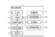
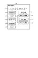
図2は、実施の形態1にかかる保全支援装置の構成例を示す図である。保全支援装置1は、管理者による電気設備の管理を支援するコンピュータである。図2に示すように、保全支援装置1は、入力部11と、記憶部である設備情報データベース16と、判定部12と、通知作成部13と、表示制御部14と、表示部15とを備えている。
なお、入力部11および設備情報データベース16は、保全支援装置1の外部に配置されてもよい。この場合、図2に示した、判定部12、通知作成部13、表示制御部14、および表示部15が保全支援装置1の構成要素となる。そして、判定部12、通知作成部13、表示制御部14、および表示部15を備えた保全支援装置1と、入力部11と、設備情報データベース16とで保全支援システムが構成される。
入力部11は、例えば、マウス、キーボードなどを含んで構成されている。入力部11は、タッチパッドであってもよい。表示部15は、例えば、液晶ディスプレイ、有機EL(ElectroLuminescence)ディスプレイなどである。表示部15の一例は、スマートフォンなどのモバイル端末の表示画面である。
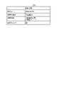
入力部11には、保全作業記録が記載された保全情報が入力される。図3は、実施の形態1にかかる保全支援装置に入力される保全情報の一例を示す図である。
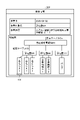
保全情報201は、作業日と、作業対象の名称(以下、作業対象名という場合がある)と、作業内容と、改訂チェック欄とを含んでいる。作業対象が、保全対象の電気設備に含まれる構成部品であり、実際に保全作業が実施された構成部品等である。作業日は、保全作業が実施された日時であり、作業対象名は、保全作業の対象となった構成部品の名称である。作業内容は、保全作業の内容を示す情報であり、改訂チェック欄は、電気設備情報の改訂が必要であるか否かを示す改訂情報である。改訂チェック欄にチェックが記載されている場合は、電気設備情報の改訂が必要であることを示す。作業対象名の例は、配電盤DAであり、作業内容の例は、回路増設工事において分岐数を2回路から3回路へと増設する工事である。
なお、保全情報201は、週次点検、月次点検などの定期的に実施される作業の情報、補修作業などの非定期に実施される作業の情報を含んでいてもよい。
設備情報データベース16は、電気設備に関する情報である電気設備情報100と、負荷設備9の情報である負荷情報101と、負荷設備9を構成する部品の情報である構成部品情報102とを格納している。ここで、電気設備情報100、負荷情報101、および構成部品情報102の構成について説明する。
図4は、実施の形態1にかかる保全支援装置に格納される電気設備情報の一例を示す図である。電気設備情報100は、電気設備が施工された際に、施工業者によって作成される。電気設備情報100は、管理者が施工業者から入手し、設備情報データベース16に予め格納しておく。
電気設備情報100は、電気設備情報100を作成した作成日の情報と、電気設備の名称(以下、電気設備名という場合がある)と、構成部品の名称(以下、構成部品名という場合がある)と、構成部品名に対応する仕様または品名の情報と、構成部品の配線関係を示す配線図とを含んでいる。
電気設備情報100に登録される電気設備名の例は、P棟電気設備である。電気設備情報100に登録される構成部品名の例は、高圧受変電設備H1、配電盤DA,DB,DC、高圧ケーブルCa、低圧ケーブルCb、エアコンA1,A2、事務機器O1,O2、およびポンプである。
電気設備情報100に登録される高圧受変電設備H1の仕様の例は、受電電圧:6.6kVである。電気設備情報100に登録される構成部品名には、負荷設備9の名称も含まれている。電気設備情報100に登録される構成部品名のうち、エアコンA1,A2、事務機器O1,O2、およびポンプが、負荷設備9の名称である。
図4に示す電気設備情報100の配線図では、高圧受変電設備H1が、1本の高圧ケーブルCaと、3本の低圧ケーブルCbとに接続されている場合を示している。また、この配線図では、高圧受変電設備H1が、1本の低圧ケーブルCbを介して配電盤DAに接続され、1本の低圧ケーブルCbを介して配電盤DBに接続され、1本の低圧ケーブルCbを介して配電盤DCに接続されている場合を示している。また、この配線図では、配電盤DAがエアコンA1,A2に接続され、配電盤DBが事務機器O1,O2に接続され、配電盤DCがポンプに接続されている場合を示している。
図5は、実施の形態1にかかる保全支援装置に格納される負荷情報の一例を示す図である。負荷情報101は、負荷設備9を導入する際に作成される情報である。負荷情報101は、管理者によって入手され、管理者によって設備情報データベース16に予め登録される。
負荷情報101は、負荷情報101を作成した作成日の情報と、負荷設備9の名称と、負荷設備9の形名と、負荷設備9の図番と、負荷設備9の電圧と、負荷設備9の電流と、低圧ケーブルCbなどの負荷設備9に接続されるケーブルの情報と、配線図とを含んでいる。負荷情報101に含まれる情報のうち、負荷設備9の電圧、電流などが負荷設備9の仕様である。負荷情報101の配線図は、配電盤DAなどの構成部品と、エアコンA1などの負荷設備9との間の配線関係を示す図である。
負荷情報101に登録される負荷設備9の名称の例は、エアコンA1である。電気設備情報100に登録される低圧ケーブルCbの例は、耐火ケーブルである。図5に示す負荷情報101の配線図では、配電盤DAが、低圧ケーブルCbを介してエアコンA1に接続されている場合を示している。
図6は、実施の形態1にかかる保全支援装置に格納される設備負荷構成部品情報の一例を示す図である。構成部品情報102は、管理者が電気設備情報100と負荷情報101とに基づいて作成するデータであり、設備情報データベース16に予め登録しておく。
構成部品情報102には、電気設備情報100に含まれる電気設備の名称と、電気設備情報100に含まれる電気設備の構成部品の各名称と、負荷情報101に含まれる負荷設備9の各名称との対応関係を示す情報が含まれている。
部品情報である構成部品情報102は、電気設備と、構成部品との間の接続関係の情報である接続情報を含んでいる。例えば、図6では、電気設備であるP棟電気設備には、構成部品である、高圧受変電設備H1、配電盤DA,DB,DC、高圧ケーブルCa、および低圧ケーブルCbが接続されていることを示している。また、配電盤DAには、エアコンA1,A2が接続され、配電盤DBには、事務機器O1,O2が接続され、配電盤DCにはポンプが接続されていることを示している。
構成部品情報102は、保全支援装置1による保全管理対象の電気設備が複数となった場合には、データの拡張が可能な構成となっている。具体的には、電気設備情報100で示すP棟電気設備に加え、Q棟電気設備が保全管理対象となる場合、図6に示すように構成部品情報102のデータを拡張してQ棟電気設備の情報を追加することが可能である。
判定部12は、入力部11に入力された保全情報201を用いて電気設備情報100の改訂が必要か否かを判定する。具体的には、判定部12は、保全情報201に含まれる改訂チェック欄のチェックの有無を検出し、チェック有りを検出すると改訂の必要があると判定する。構成部品情報102に複数の電気設備が登録されている場合、判定部12は、複数の電気設備に対して電気設備情報100の改訂が必要か否かを判定する。
判定部12は、改訂の必要がある場合、保全情報201に含まれる作業対象名を抽出し、抽出した作業対象名と、構成部品情報102内の構成部品の名称とを比較する。電気設備情報100に登録されている構成部品名、すなわち構成部品情報102に含まれている構成部品名が第1の構成部品の名称である。また、保全情報201に含まれる作業対象名が、第2の構成部品の名称である。
判定部12は、保全情報201および構成部品情報102に基づいて、変更された電気設備を特定する。具体的には、判定部12は、保全情報201から、作業対象名(図3の場合は、配電盤DA)を抽出し、抽出した作業対象名を含む電気設備を、改訂対象の電気設備に設定する。
すなわち、判定部12は、構成部品情報102に含まれる構成部品名のうち作業対象名に一致する構成部品名を探索し、作業対象名に一致する構成部品名が属する電気設備名を改訂対象の電気設備名に設定する。
改訂対象は、電気設備が改訂されたことを管理者に通知する際の、通知内容(後述する通知内容121)に含める電気設備の名称である。すなわち、改訂対象に設定される電気設備名が、保全作業によって変更が行われた電気設備の電気設備名である。判定部12は、設定した改訂対象の電気設備名と、保全情報201とを通知作成部13に送る。
通知作成部13は、判定部12から、改訂対象の電気設備名と、保全情報201とを受け取る。通知作成部13は、電気設備名および保全情報201に基づいて、通知内容121を作成する。通知内容121は、電気設備情報100に改訂が必要であることを通知するための情報である。通知作成部13は、作成した通知内容121を表示制御部14に送る。
表示制御部14は、通知作成部13から通知内容121を受け取り、通知内容121を示す後述の通知画面120を表示部15に表示させる。電気設備情報100に対する改訂通知は、管理者に、電気設備情報100の改訂が必要であることを通知する処理である。管理者は、改訂通知に含まれる電気設備名に対応する電気設備情報100を改訂することで、保全作業後の構成部品と、電気設備情報100に含まれる構成部品とを一致させる。電気設備情報100に関連した図面等が紙である場合、管理者は、表示部15に表示されている通知画面120を参照して電気設備情報100に関連した図面等を探し出して改訂する。電気設備情報100に関連した図面等が電子化されている場合、通知内容121には、電子化された図面等を呼び出すリンクを含めておく。これにより、管理者は、リンクをクリックするだけで必要な図面等を探し出すことが可能となる。
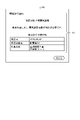
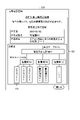
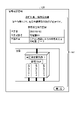
図7は、実施の形態1にかかる保全支援装置が通知画面に表示させる通知内容を説明するための図である。表示部15は、表示制御部14からの指示に従って、通知内容121を示す通知画面120を表示する。
通知内容121には、電気設備情報100などの情報に改訂が必要であることを示すメッセージ、例えば、「情報改訂通知」などが含まれている。また、通知内容121には、改訂対象の電気設備名、電気設備情報100の改訂が必要な理由、管理者に参照させる保全作業の記録などが含まれている。
改訂対象の電気設備名は、判定部12が、構成部品情報102に基づいて設定した電気設備の名称である。図7の通知内容121では、改訂対象の電気設備名がP棟電気設備である場合を示している。また、図7の通知内容121では、電気設備情報100の改訂が必要な理由が保全作業の実施である場合を示している。
管理者に参照させる保全作業の記録である参照保全作業記録には、保全作業の作業日、保全作業が行われた構成部品の作業対象名、保全作業の作業内容などが含まれている。作業対象名は、判定部12が、構成部品情報102に基づいて設定した構成部品の名称である。図7の通知内容121では、参照保全作業記録における作業対象名は、配電盤DAである。参照保全作業記録は、保全情報201に基づいて作成される。
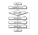
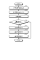
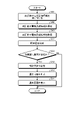
次に、図8に示すフローチャートを用いて保全支援装置1による電気設備情報100の改訂通知処理を説明する。図8は、実施の形態1にかかる保全支援装置による電気設備情報の改訂通知処理の処理手順を示すフローチャートである。
入力部11へは、保全作業を行った保全作業員によって保全情報201が入力される。入力部11は、保全情報201を受け付ける(ステップS10)。
次に、判定部12は、入力部11から保全情報201を受け取り、保全情報201に含まれる改訂チェック欄のチェックの判定を検出する(ステップS11)。判定部12は、チェック有りの場合(ステップS11、Yes)、改訂の必要があると判定する。判定部12は、チェック無しの場合(ステップS11、No)、改訂の必要が無いと判定し、通知処理を終了する。
次に、判定部12は、改訂の必要があると判定した保全情報201から、作業対象名を抽出する。そして、判定部12は、作業対象名と、構成部品情報102とを比較することによって、構成部品情報102内から作業対象名に対応する構成部品を抽出する。判定部12は、改訂対象として、抽出した構成部品を含んだ電気設備名を設定する(ステップS12)。
判定部12は、例えば、保全情報201から作業対象名として配電盤DAを抽出すると、構成部品情報102内から配電盤DAを含んだ電気設備名であるP棟電気設備を選択して改訂対象を設定する。判定部12は、設定した改訂対象の電気設備名と、保全情報201とを通知作成部13に送る。
通知作成部13は、判定部12から改訂対象の電気設備名と、保全情報201とを受け付け、電気設備名および保全情報201に基づいて、例えば、図7に示した通知内容121を作成する(ステップS13)。
表示制御部14は、通知作成部13から通知内容121を受け取り、通知画面120を表示部15に表示させる(ステップS14)。
例えば、電力需要家設備3などで保全作業が実施されると、電力需要家設備3内での配線または配置が変更される場合がある。この場合、配線図または配置図といった電気図面に関する情報を含んだ電気設備情報100も併せて修正することが望まれる。未修正の電気設備情報100では、電気設備工事に対する実態調査費が高くなり、トラブル発生時の復旧が遅れるといった運営上の問題が発生する場合があるからである。実施の形態1の保全支援装置1は、保全作業などによる電気設備の変更によって電気設備情報100の改訂が必要なことを自動検知し、改訂が必要な電気設備情報100を管理者に通知する。
なお、実施の形態1では、保全支援装置1が、保全情報201および構成部品情報102に基づいて電気設備情報100の改訂が必要か否かを判定するので、電気設備情報100および負荷情報101は、必ずしも必要ではない。
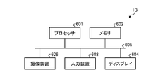
図9は、実施の形態1にかかる保全支援装置のハードウェア構成の一例を示す図である。図9に示すように、保全支援装置1は、プロセッサ601と、メモリ602と、入力装置603と、ディスプレイ604とにより実現することができる。
プロセッサ601は、処理回路の一例である。プロセッサ601の例は、CPU(中央処理装置、処理装置、演算装置、マイクロプロセッサ、マイクロコンピュータ、DSP(Digital Signal Processor)ともいう)またはシステムLSI(Large Scale Integration)である。メモリ602の例は、RAM(Random Access Memory)、ROM(Read Only Memory)である。
プロセッサ601、メモリ602、入力装置603、およびディスプレイ604は、例えば、バス605によって互いに情報の送受信が可能である。入力部11は、入力装置603によって実現される。表示部15は、ディスプレイ604によって実現される。設備情報データベース16は、メモリ602によって実現される。
保全支援装置1は、プロセッサ601が、メモリ602で記憶されている保全支援装置1の動作を実行するための、コンピュータで実行可能な、保全支援プログラムを読み出して実行することにより実現される。保全支援装置1の動作を実行するためのプログラムである保全支援プログラムは、保全支援装置1の手順または方法をコンピュータに実行させるものであるともいえる。
入力装置603は、保全情報201を受け付けてプロセッサ601に送る。メモリ602は、保全支援プログラム、電気設備情報100、負荷情報101、および構成部品情報102を記憶する。
プロセッサ601は、メモリ602に記憶された保全支援プログラムを読み出して実行することによって、判定部12、通知作成部13、および表示制御部14の機能を実行する。すなわち、保全支援装置1で実行される保全支援プログラムは、判定部12、通知作成部13、および表示制御部14を含むモジュール構成となっており、これらが主記憶装置上にロードされ、これらが主記憶装置上に生成される。
保全支援プログラムは、インストール可能な形式または実行可能な形式のファイルで、コンピュータが読み取り可能な記憶媒体に記憶されてコンピュータプログラムプロダクトとして提供されてもよい。また、保全支援プログラムは、インターネットなどのネットワーク経由で保全支援装置1に提供されてもよい。なお、保全支援装置1の機能について、一部を専用回路などの専用のハードウェアで実現し、一部をソフトウェアまたはファームウェアで実現するようにしてもよい。
以上のように、実施の形態1にかかる保全支援装置1は、判定部12と通知作成部13とを備えている。判定部12は、保全情報201に基づいて、電気設備に関する電気設備情報100の改訂が必要か否かを判定する。電気設備情報100の改訂が必要な場合、判定部12は、保全情報201から作業対象名を抽出して、改訂対象の作業対象名に設定する。判定部12は、作業対象名と構成部品情報102とを比較し、改訂対象となる電気設備名を決定する。通知作成部13は、電気設備名、および構成部品情報102に基づいて、改訂対象となる電気設備名および作業対象名が記載された通知内容121を作成する。表示制御部14は、通知作成部13から通知内容121を受け取り、通知内容121を示す通知画面120を表示部15に表示させる。これにより、保全支援装置1は、保全作業に応じて改訂が必要な電気設備情報100を電気設備の管理者に提示することができる。
実施の形態2.
次に、図10および図11を用いて実施の形態2について説明する。実施の形態2の保全支援装置1は、保全情報201に基づいて、電気設備情報100および負荷情報101の改訂が必要か否かを判定し、判定結果に基づいて、電気設備情報100および負荷情報101の改訂通知を行う。電気設備情報100および負荷情報101の改訂通知は、管理者に、電気設備情報100および負荷情報101の改訂が必要であることを通知する処理である。
次に、図10および図11を用いて実施の形態2について説明する。実施の形態2の保全支援装置1は、保全情報201に基づいて、電気設備情報100および負荷情報101の改訂が必要か否かを判定し、判定結果に基づいて、電気設備情報100および負荷情報101の改訂通知を行う。電気設備情報100および負荷情報101の改訂通知は、管理者に、電気設備情報100および負荷情報101の改訂が必要であることを通知する処理である。
実施の形態2の保全支援装置1の構成は、実施の形態1の保全支援装置1の構成と同じであるので、その説明は省略する。
実施の形態2にかかる保全支援装置1は、保全情報201に基づいて、電気設備情報100および負荷情報101の改訂が必要か否かを判定し、改訂が必要な場合には、電気設備情報100および負荷情報101の改訂を要求するための通知を行う。
以下の説明では、実施の形態1の保全支援装置1が実行する処理と同様の処理については、その説明を省略し、実施の形態1の保全支援装置1とは異なる処理を中心に説明する。
図10は、実施の形態2にかかる保全支援装置に入力される保全情報の一例を示す図である。保全情報202は、保全情報201と同様に、作業日と、作業対象名と、作業内容と、改訂チェック欄とを含んでいる。図10の保全情報202では、作業対象名がエアコンA1であり、作業内容が、老朽化のため交換であり、小型エアコン(電流20A)に変更された場合を示している。
実施の形態2では、エアコンA1が交換されたことにより負荷設備9が変更されており、電気設備情報100に加えて負荷情報101も改訂が必要となっている。
実施の形態2の保全支援装置1は、図8で説明した実施の形態1の保全支援装置1と同様の処理手順によって管理者への改訂通知処理を実行する。実施の形態2では、入力部11が保全情報202を受け付ける(ステップS10)。判定部12は、保全情報202に含まれる改訂チェック欄のチェックの有無を判定する(ステップS11)。判定部12は、チェック有りの場合(ステップS11、Yes)、改訂の必要があると判定する。判定部12は、チェック無しの場合(ステップS11、No)、改訂の必要が無いと判定し、通知処理を終了する。
次に、判定部12は、改訂の必要があると判定した保全情報202から、作業対象名を抽出する。そして、判定部12は、作業対象名と、構成部品情報102とを比較することによって、構成部品情報102内から作業対象名に対応する構成部品を抽出する。ここでの作業対象名は、構成部品のうちの負荷設備9の名称であるので、判定部12は、構成部品情報102内から、作業対象名に対応する負荷設備9を抽出する。また、判定部12は、抽出した負荷設備9が属する電気設備名を構成部品情報102内から抽出する。
判定部12は、改訂対象として、抽出した負荷設備9および電気設備名を設定する(ステップS12)。
通知作成部13は、判定部12から改訂対象の電気設備名および負荷設備名と、保全情報202とを受け付け、例えば、後述する通知内容123を作成する(ステップS13)。
表示制御部14は、通知作成部13から通知内容123を受け取り、後述する通知画面122を表示部15に表示させる(ステップS14)。
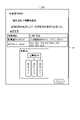
図11は、実施の形態2にかかる保全支援装置が通知画面に表示させる通知内容を説明するための図である。なお、図11に示す通知内容123に含まれる情報のうち図7で説明した通知内容121に含まれる情報と同様の情報については、重複する説明は省略する。
表示部15は、表示制御部14からの指示に従って、通知内容123を示す通知画面122を表示する。
通知内容123には、電気設備情報100および負荷情報101に改訂が必要であることを示すメッセージが含まれている。また、通知内容123には、改訂対象の電気設備名、改訂対象の負荷設備名、電気設備情報100および負荷情報101の改訂が必要な理由、管理者に参照させる参照保全作業記録などが含まれている。
改訂対象の負荷設備名は、判定部12が、構成部品情報102に基づいて設定した負荷設備9の名称である。図11の通知内容123では、改訂対象の電気設備名がP棟電気設備であり、改訂対象の負荷設備名がエアコンA1である場合を示している。また、図11の通知内容123では、電気設備情報100および負荷情報101の改訂が必要な理由が保全作業の実施である場合を示している。
管理者に参照させる保全作業の記録である参照保全作業記録には、保全作業の作業日、保全作業が行われた作業対象名、保全作業の作業内容などが含まれている。作業対象名は、判定部12が、構成部品情報102に基づいて設定した作業対象名である。図11の通知内容123では、参照保全作業記録の作業対象名は、エアコンA1である。
なお、実施の形態2では、保全支援装置1が、保全情報202および構成部品情報102に基づいて電気設備情報100の改訂が必要か否かを判定するので、電気設備情報100および負荷情報101は、必ずしも必要ではない。
以上のように、実施の形態2にかかる保全支援装置1は、判定部12と通知作成部13とを備えている。判定部12は、保全情報202に基づいて、電気設備情報100および負荷情報101の改訂が必要か否かを判定する。電気設備情報100および負荷情報101の改訂が必要な場合、判定部12は、保全情報202から作業対象名を抽出して改訂対象の作業対象名に設定する。判定部12は、作業対象名と構成部品情報102とを比較し、改訂対象となる負荷設備名および電気設備名を決定する。通知作成部13は、負荷設備名、電気設備名、および構成部品情報102に基づいて、通知内容123を作成する。表示制御部14は、通知作成部13から通知内容123を受け取り、通知内容123を示す通知画面122を表示部15に表示させる。これにより、保全支援装置1は、保全作業に応じて改訂が必要な電気設備情報100および負荷情報101を電気設備の管理者に提示することができる。
実施の形態3.
次に、図12から図15を用いて実施の形態3について説明する。実施の形態3の保全支援装置は、保全作業者によって保全情報に書き込まれた配線図と、電気設備情報100に含まれる配線図とを比較することで、電気設備情報100を改訂する必要があるか否かを判定する。
次に、図12から図15を用いて実施の形態3について説明する。実施の形態3の保全支援装置は、保全作業者によって保全情報に書き込まれた配線図と、電気設備情報100に含まれる配線図とを比較することで、電気設備情報100を改訂する必要があるか否かを判定する。
図12は、実施の形態3にかかる保全支援装置の構成例を示す図である。図12の各構成要素のうち図2に示す実施の形態1の保全支援装置1と同一機能を達成する構成要素については同一符号を付しており、重複する説明は省略する。
実施の形態3にかかる保全支援装置1Aは、保全情報に含まれる配線図を用いて、電気設備情報100の改訂が必要か否かを判定し、改訂が必要であると判定した場合に、改訂通知を行う点で、実施の形態1にかかる保全支援装置1と異なる。保全支援装置1Aは、保全情報に含まれる配線図が、電気設備情報100に含まれる配線図と異なる場合に改訂通知を行う。
図12に示すように、保全支援装置1Aは、入力部11と、設備情報データベース16と、判定部12と、通知作成部13と、表示制御部14と、表示部15と、取得部17と、比較部18とを備えている。保全支援装置1Aが備える設備情報データベース16は、保全支援装置1が備える設備情報データベース16と同様の情報を記憶する。
保全支援装置1Aの入力部11には、保全作業記録が記載された保全情報が入力される。図13は、実施の形態3にかかる保全支援装置に入力される保全情報の一例を示す図である。
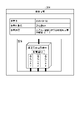
保全情報203は、作業日と、作業対象名と、作業内容と、配線図とを含んでいる。電気設備情報100に含まれる配線図が第1の配線図であり、保全情報203に含まれる配線図が第2の配線図である。保全情報203に含まれる配線図は、例えば、保全作業の際に保全作業者によって手書き等にて入力された入力情報110が含まれている。図13に示す保全情報203での入力情報110は、エアコンA3である。
取得部17は、入力部11に入力された保全情報203を受け取り、保全情報203から作業対象名を抽出する。取得部17は、保全情報203から抽出した作業対象名と、構成部品情報102に含まれる構成部品とを比較する。取得部17は、構成部品情報102の中から作業対象名に一致する構成部品を抽出し、抽出した構成部品に対応する電気設備情報100を設備情報データベース16から取得する。
なお、保全情報203から抽出した作業対象名が、構成部品情報102に含まれる負荷設備9に一致する場合、取得部17が設備情報データベース16から取得する情報は電気設備情報100および負荷情報101となる。図13に示す保全情報203の場合、作業対象名は配電盤DAであるので、取得部17は、設備情報データベース16から電気設備情報100を取得する。
比較部18は、取得部17から保全情報203および電気設備情報100を受け取り、保全情報203に含まれる配線図と電気設備情報100に含まれる配線図とを比較する。このとき、比較部18は、保全情報203の配線図および電気設備情報100の配線図をPDF(Portable Document Format)のデータとして読み出し、PDFのデータをPDF差分抽出ソフト(例えば、Acrobat(登録商標))に入力する。比較部18は、PDF差分抽出ソフトを用いて配線図の比較処理を実行することで、配線図の差異を検出する。
保全作業で保全情報203の配線図に入力情報110が入力された場合には、保全情報203の配線図と電気設備情報100の配線図との間に差異が発生するので、比較部18は、この差異を抽出する。すなわち、比較部18は、配線図の比較処理結果に基づいて、保全作業で入力された入力情報110の有無を判定する。比較部18は、配線図の差異を示す情報を配線図差異情報として判定部12に送る。
判定部12は、配線図差異情報を受け取る。判定部12は、配線図差異情報に基づいて、電気設備情報100を改訂する必要があるか否かを判定する。なお、判定部12は、保全情報203から抽出された作業対象名が、構成部品情報102に含まれる負荷設備9に一致する場合、配線図差異情報に基づいて、電気設備情報100および負荷情報101を改訂する必要があるか否かを判定する。
保全情報203内の配線図に保全作業で入力された情報がある場合、判定部12は、電気設備情報100を改訂する必要があると判定する。判定部12は、配線図差異情報に基づいて、改訂の必要がある電気設備情報100を特定する。
保全支援装置1Aが備える、通知作成部13、表示制御部14、および表示部15は、保全支援装置1が備える、通知作成部13、表示制御部14、および表示部15と同様の機能を有しており、同様の処理を実行する。なお、保全支援装置1Aは、実施の形態1で説明した保全支援装置1と同様のハードウェア構成を有している。
以下の説明では、実施の形態1の保全支援装置1が実行する処理と同様の処理については、その説明を省略し、実施の形態1の保全支援装置1とは異なる処理を中心に説明する。
図14は、実施の形態3にかかる保全支援装置が通知画面に表示させる通知内容を説明するための図である。なお、図14に示す通知内容125に含まれる情報のうち図7で説明した通知内容121に含まれる情報と同様の情報については、重複する説明は省略する。
表示部15は、表示制御部14からの指示に従って、通知内容125を示す通知画面124を表示する。
通知内容125には、電気設備情報100などの電気設備の情報に改訂が必要であることを示すメッセージが含まれている。また、通知内容125には、改訂対象の電気設備名、電気設備情報100の改訂が必要な理由、管理者に参照させる参照保全作業記録などが含まれている。また、通知内容125には、最新の保全情報203の配線図と同じ配線図が含まれている。すなわち、保全情報203内の配線図に保全作業で入力された入力情報110がある場合、通知内容125には、この入力情報110が記載された配線図が含まれている。
表示部15は、通知内容125に含まれる情報のうち、入力情報110がどの情報であるかを識別できる態様で、通知内容125を示す通知画面124を表示する。
次に、図15に示すフローチャートを用いて保全支援装置1Aによる電気設備情報100の改訂通知処理を説明する。図15は、実施の形態3にかかる保全支援装置による電気設備情報の改訂通知処理の処理手順を示すフローチャートである。
入力部11へは、保全作業を行った保全作業員によって保全情報203が入力される。入力部11は、保全情報203を受け付ける(ステップS10)。
次に、取得部17は、入力部11から保全情報203を受け取り、保全情報203に含まれる作業対象名を抽出する。さらに、取得部17は、構成部品情報102から作業対象名に一致する構成部品を抽出する。そして、取得部17は、抽出した構成部品に対応する電気設備情報100を設備情報データベース16から取得する(ステップS21)。
次に、比較部18は、取得部17から保全情報203および電気設備情報100を受け取り、保全情報203に含まれる配線図および電気設備情報100に含まれる配線図を抽出して比較する(ステップS22)。
比較部18は、配線図の差異を示す配線図差異情報を判定部12に送る。判定部12は、配線図差異情報に基づいて、配線図に差異があるか否かを判定する(ステップS23)。すなわち、判定部12は、電気設備情報100を改訂する必要があるか否かを判定する。
配線図に差異がある場合(ステップS23、Yes)、判定部12は、電気設備情報100を改訂する必要があると判定する。電気設備情報100を改訂する必要がある場合、保全支援装置1Aは、実施の形態1から3で説明したステップS12からS14の処理を実行する。
すなわち、判定部12は、保全情報203から、作業対象名を抽出し、構成部品情報102内から作業対象名に対応する構成部品を抽出する。判定部12は、改訂対象として、抽出した構成部品を含んだ電気設備名を設定する(ステップS12)。
通知作成部13は、判定部12から改訂対象の電気設備名と、保全情報203とを受け付け、例えば、図14に示した通知内容125を作成する(ステップS13)。
表示制御部14は、通知作成部13から通知内容125を受け取り、通知画面124を表示部15に表示させる(ステップS14)。配線図に差異がない場合(ステップS23、No)、判定部12は、改訂の必要が無いと判定し、通知処理を終了する。
なお、実施の形態3では、保全支援装置1Aが、保全情報203、構成部品情報102、および電気設備情報100に基づいて電気設備情報100の改訂が必要か否かを判定するので、負荷情報101は、必ずしも必要ではない。保全支援装置1Aは、保全対象が構成部品である場合に負荷情報101を用いる。
以上のように、実施の形態3にかかる保全支援装置1Aは、取得部17と、比較部18と、判定部12とを備えている。取得部17は、保全作業で変更された保全情報203の配線図と、設備情報データベース16に登録されている電気設備情報100の配線図とを取得する。比較部18は、保全情報203の配線図と電気設備情報100の配線図との比較を行い、配線図の差異を抽出する。判定部12は、配線図に差異がある場合には、電気設備情報100の改訂が必要であると判定する。これにより、保全支援装置1Aは、保全作業者に、改訂チェック欄への改訂チェックの入力をさせることなく、改訂が必要な電気設備情報100を管理者に提示することができる。
また、入力情報110として入力された設備が、エアコンA1といった負荷設備9である場合、保全支援装置1Aは、保全作業者に、改訂チェック欄への改訂チェックの入力をさせることなく、改訂が必要な電気設備情報100および負荷情報101を管理者に提示することができる。
実施の形態4.
次に、図16から図20を用いて実施の形態4について説明する。実施の形態4の保全支援装置は、保全対象設備である作業対象となった電気設備である作業対象設備の画像に基づいて、電気設備情報100の改訂が必要であるか否かを判定する。
次に、図16から図20を用いて実施の形態4について説明する。実施の形態4の保全支援装置は、保全対象設備である作業対象となった電気設備である作業対象設備の画像に基づいて、電気設備情報100の改訂が必要であるか否かを判定する。
図16は、実施の形態4にかかる保全支援装置の構成例を示す図である。図16の各構成要素のうち図2に示す実施の形態1の保全支援装置1と同一機能を達成する構成要素については同一符号を付しており、重複する説明は省略する。
実施の形態4にかかる保全支援装置1Bは、作業対象設備の画像を含む保全情報から、構成部品等の名称を示す文字情報を抽出する。保全支援装置1Bは、抽出した文字情報を用いて、電気設備情報100の改訂が必要か否かを判定し、改訂が必要であると判定した場合に、改訂通知を行う点で、実施の形態1にかかる保全支援装置1と異なる。保全支援装置1Bは、抽出した文字情報に対応する構成部品等と、構成部品情報102に含まれている構成部品とが異なる場合に、電気設備情報100の改訂通知を行う。
図16に示すように、保全支援装置1Bは、入力部11と、設備情報データベース16と、判定部12と、通知作成部13と、表示制御部14と、表示部15とを備えている。また、保全支援装置1Bは、撮像部19と、画像解析部20とを備えている。保全支援装置1Bが備える設備情報データベース16は、保全支援装置1が備える設備情報データベース16と同様の情報を記憶する。
撮像部19の例は、画像である写真を撮像するカメラである。撮像部19は、デジタルカメラであってもよいし、スマートフォンといった携帯端末が備えるカメラであってもよい。撮像部19は、作業対象設備の画像を生成し、入力部11に送る。
保全支援装置1Bの入力部11には、撮像部19から送られてくる、作業対象設備の画像が入力される。また、入力部11へは、保全作業を行った保全作業員によって保全情報が入力される。この保全情報は、実施の形態3の図13で説明した保全情報203から配線図が除去された情報である。入力部11は、保全作業員からの保全情報を受け付ける。入力部11は、保全作業員によって入力された保全情報に、撮像部19で撮像された画像を添付することで、画像を備えた後述の保全情報204を生成する。
なお、保全作業員によって入力される保全情報204に画像が添付されていてもよい。この場合、保全作業員によって保全情報204に画像が添付される。
図17は、実施の形態4にかかる保全支援装置の入力部が生成する保全情報の一例を示す図である。保全情報204は、作業日と、作業対象名と、作業内容と、撮像部19が撮像した作業対象設備の画像とを含んでいる。図17では、作業対象が配電盤DAであり、撮像部19によって配電盤DAを含んだ作業対象設備の画像が撮像された場合を示している。
画像解析部20は、入力部11から保全情報204を受け取り、撮像部19で撮像された画像を解析する。作業対象設備に含まれる構成部品には、予めテプラ(登録商標)などのラベルライターを用いて構成部品の名称を示す文字情報が貼り付けられている。したがって、撮像部19で撮像された画像には、文字情報を示すラベルが含まれている。
画像解析部20は、文字情報を示すラベルを含んだ画像に対し、文字認識アプリケーション(例えば、Google Lens(登録商標))を用いて画像に含まれる文字情報を読取り、テキストデータに変換する。
判定部12は、保全情報204とともに、画像解析部20が保全情報204に含まれる画像を解析して抽出したテキストデータを、画像解析部20から受け取る。また、判定部12は、設備情報データベース16から構成部品情報102を取得する。判定部12は、テキストデータと、構成部品情報102とを比較し、電気設備情報100の改訂が必要であるか否かを判定する。
例えば、図17に示した保全情報204の場合、判定部12が画像解析部20から受け取るテキストデータには、配電盤DA、高圧受変電設備H1、エアコンA1、エアコンA2、およびエアコンA3の各名称が含まれる。これらのテキストデータに対応する構成部品のうち、構成部品情報102には、エアコンA1のテキストデータに対応する構成部品が無いので、判定部12は、構成部品に差異が有ると判定する。また、これらのテキストデータに対応する電気設備は、P棟電気設備に含まれる電気設備であるので、判定部12は、改訂通知の対象とする電気設備名をP棟電気設備に設定する。
保全支援装置1Bが備える、通知作成部13、表示制御部14、および表示部15は、保全支援装置1が備える、通知作成部13、表示制御部14、および表示部15と同様の機能を有しており、同様の処理を実行する。
以下の説明では、実施の形態1の保全支援装置1が実行する処理と同様の処理については、その説明を省略し、実施の形態1の保全支援装置1とは異なる処理を中心に説明する。
図18は、実施の形態4にかかる保全支援装置が通知画面に表示させる通知内容を説明するための図である。なお、図18に示す通知内容127に含まれる情報のうち図7で説明した通知内容121に含まれる情報と同様の情報については、重複する説明は省略する。
表示部15は、表示制御部14からの指示に従って、通知内容127を示す通知画面126を表示する。
通知内容127には、電気設備情報100などの電気設備の情報に改訂が必要であることを示すメッセージが含まれている。また、通知内容127には、改訂対象の電気設備名、電気設備情報100の改訂が必要な理由、管理者に参照させる参照保全作業記録などが含まれている。また、通知内容127には、撮像部19で撮像された、作業対象設備の画像が含まれている。
次に、図19に示すフローチャートを用いて保全支援装置1Bによる電気設備情報100の改訂通知処理を説明する。図19は、実施の形態4にかかる保全支援装置による電気設備情報の改訂通知処理の処理手順を示すフローチャートである。
保全支援装置1Bの撮像部19は、保全作業を行った作業対象設備の画像を撮像する(ステップS31)。入力部11へは、撮像部19から送られてくる、作業対象設備の画像が入力される。
また、入力部11へは、保全作業を行った保全作業員によって、画像添付前の保全情報が入力される。入力部11は、保全作業員からの画像添付前の保全情報を受け付ける(ステップS10)。入力部11は、保全作業員によって入力された保全情報に、撮像部19で撮像された画像を添付することで、画像を備えた保全情報204を生成する。
次に、画像解析部20は、入力部11から保全情報204を受け取り、保全情報204に添付された画像を解析する(ステップS32)。画像解析部20は、文字情報を示すラベルを含んだ画像に対し、文字認識アプリケーションを用いて画像に含まれる文字を読取り、テキストデータに変換する。
判定部12は、画像解析部20から保全情報204を受け取る。また、判定部12は、画像解析部20が画像を解析して抽出したテキストデータを、画像解析部20から受け取る。また、判定部12は、設備情報データベース16から構成部品情報102を取得する。判定部12は、テキストデータと、構成部品情報102とを比較する。判定部12は、テキストデータで示される構成部品と、構成部品情報102に含まれる構成部品とを比較する。
判定部12は、テキストデータで示される構成部品と、構成部品情報102に含まれる構成部品とに基づいて、構成部品に差異があるか否かを判定する(ステップS33)。すなわち、判定部12は、電気設備情報100を改訂する必要があるか否かを判定する。
構成部品に差異がある場合(ステップS33、Yes)、判定部12は、電気設備情報100を改訂する必要があると判定する。なお、構成部品の内の負荷設備9に差異がある場合、判定部12は、電気設備情報100および負荷情報101を改訂する必要があると判定する。この後、保全支援装置1Bは、実施の形態1,2で説明したステップS12からS14の処理を実行する。
構成部品に差異がない場合(ステップS33、No)、判定部12は、改訂の必要が無いと判定し、通知処理を終了する。
なお、実施の形態4では、保全支援装置1Bが、保全情報204、構成部品情報102、および電気設備情報100に基づいて電気設備情報100の改訂が必要か否かを判定するので、負荷情報101は、必ずしも必要ではない。保全支援装置1Bは、保全対象が構成部品である場合に負荷情報101を用いる。
図20は、実施の形態4にかかる保全支援装置のハードウェア構成の一例を示す図である。なお、図20の各構成要素のうち図9に示す実施の形態1の保全支援装置1のハードウェア構成と同一機能を達成する構成要素については同一符号を付しており、重複する説明は省略する。
図20に示すように、保全支援装置1Bは、プロセッサ601と、メモリ602と、入力装置603と、ディスプレイ604と、撮像装置606とにより実現することができる。撮像部19は、画像を撮像する装置である撮像装置606によって実現される。
保全支援装置1Bのプロセッサ601は、メモリ602に記憶された保全支援プログラムを読み出して実行することによって、画像解析部20、判定部12、通知作成部13、および表示制御部14の機能を実行する。すなわち、保全支援装置1Bで実行される保全支援プログラムは、画像解析部20、判定部12、通知作成部13、および表示制御部14を含むモジュール構成となっており、これらが主記憶装置上にロードされ、これらが主記憶装置上に生成される。
以上のように、実施の形態4にかかる保全支援装置1Bは、撮像部19と、画像解析部20と、判定部12とを備えている。撮像部19は、作業対象設備の画像を取得する。画像解析部20は、保全情報204に添付された画像を解析することによって、画像から構成部品の名称を示す文字を読取り、テキストデータに変換する。判定部12は、テキストデータで示される構成部品と、構成部品情報102に含まれる構成部品とを比較し、構成部品に差異があれば電気設備情報100の改訂が必要であると判定する。これにより、保全支援装置1Bは、保全作業者に、改訂チェック欄への改訂チェックの入力をさせることなく、改訂が必要な電気設備情報100を管理者に提示することができる。
また、差異のあった構成部品が、エアコンA1といった負荷設備9である場合、保全支援装置1Bは、保全作業者に、改訂チェック欄への改訂チェックの入力をさせることなく、改訂が必要な電気設備情報100および負荷情報101を管理者に提示することができる。
実施の形態5.
次に、図21から図24を用いて実施の形態5について説明する。実施の形態5の保全支援装置は、改訂後の電気設備情報と改訂前の電気設備情報100とに基づいて、電気設備が変更されたことを確認する必要があるか否かを判定する。実施の形態5の保全支援装置は、電気設備が変更されたことを確認する必要があると判定した場合に、電気設備の変更確認が必要であることを示す通知内容を作成して出力する。
次に、図21から図24を用いて実施の形態5について説明する。実施の形態5の保全支援装置は、改訂後の電気設備情報と改訂前の電気設備情報100とに基づいて、電気設備が変更されたことを確認する必要があるか否かを判定する。実施の形態5の保全支援装置は、電気設備が変更されたことを確認する必要があると判定した場合に、電気設備の変更確認が必要であることを示す通知内容を作成して出力する。
図21は、実施の形態5にかかる保全支援装置の構成例を示す図である。図21の各構成要素のうち図12に示す実施の形態3の保全支援装置1Aと同一機能を達成する構成要素については同一符号を付しており、重複する説明は省略する。
実施の形態5にかかる保全支援装置1Cは、改訂後の電気設備情報100と改訂前の電気設備情報100との比較により、電気設備情報100の修正箇所を抽出し、管理者に修正箇所を通知するという点で実施の形態3にかかる保全支援装置1Aと異なる。
図21に示すように、保全支援装置1Cは、入力部11と、設備情報データベース16と、判定部12と、通知作成部13と、表示制御部14と、表示部15と、取得部17と、比較部18と、情報更新部21とを備えている。
入力部11へは、管理者によって修正によって改訂された電気設備情報103が入力される。入力部11は、電気設備情報103を受け付けて、情報更新部21に送る。
情報更新部21は、入力部11から改訂後の電気設備情報103を受け取り、設備情報データベース16に改訂後の電気設備情報103を保存する。また、情報更新部21は、改訂後の電気設備情報103を取得部17に送る。なお、保全支援装置1Cは、実施の形態1で説明した保全支援装置1と同様のハードウェア構成を有している。
以下の説明では、実施の形態3の保全支援装置1Aが実行する処理と同様の処理については、その説明を省略し、実施の形態3の保全支援装置1Aとは異なる処理を中心に説明する。
図22は、実施の形態5にかかる保全支援装置の入力部に入力される改訂後の電気設備情報の一例を示す図である。なお、図22に示す電気設備情報103に含まれる情報のうち図4で説明した電気設備情報100に含まれる情報と同様の情報については、重複する説明は省略する。
改訂後の電気設備情報103は、改訂前の電気設備情報100と比較して、構成部品名のエアコンA3が追加され、配電盤DAの分岐回路数が2回路から3回路に変更され、配線図にエアコンA3が追加されている。
取得部17は、情報更新部21から改訂後の電気設備情報103を受け取り、設備情報データベース16から改訂前の電気設備情報100を取得する。取得部17は、取得した電気設備情報100および電気設備情報103を比較部18に送る。
比較部18は、改訂前の電気設備情報である電気設備情報100と、改訂後の電気設備情報である電気設備情報103とを比較し、電気設備情報100,103の差異を検出する。ここでの比較部18は、実施の形態3で説明した方法と同様の処理によって、配線図の差異を検出する。すなわち、比較部18は、改訂前の電気設備情報100に含まれている配線図と、改訂後の電気設備情報103に含まれている配線図との差異を検出する。比較部18は、電気設備情報100,103の差異を示す情報を改訂差異情報として判定部12に送る。
判定部12は、改訂差異情報を受け取る。判定部12は、改訂差異情報に基づいて、電気設備情報100,103に差異があるか否かを判定する。判定部12は、電気設備情報100,103に差異がある場合、電気設備情報100,103の差異を示す改訂差異情報を通知作成部13に送る。改訂差異情報は、電気設備情報100から電気設備情報103への改訂箇所を示す情報である。
通知作成部13は、判定部12から送られてくる判定結果を受け取り、後述する通知内容131を決定する。具体的には、通知作成部13は、改訂差異情報に基づいて、改訂された箇所であると判断された箇所の位置を含んだ、改訂箇所の周囲を切り出し、切出した領域に基づいて通知内容131を作成する。
通知作成部13は、作成した通知内容131を表示制御部14に送る。表示制御部14は、通知作成部13から通知内容131を受け取り、通知内容131を示す後述の通知画面130を表示部15に表示させる。表示部15は、表示制御部14からの指示に従って、通知内容131を示す通知画面130を表示する。
図23は、実施の形態5にかかる保全支援装置が通知画面に表示させる通知内容を説明するための図である。なお、図23の通知内容131に含まれる情報のうち図14で説明した通知内容125に含まれる情報と同様の情報については、重複する説明は省略する。
通知内容131は、電気設備の修正を確認する必要があることを通知するための情報である。通知内容131には、電気設備に対して正しい修正が行われたか否かの確認が必要であることを示すメッセージ、例えば、「設備確認通知」などが含まれている。また、通知内容131には、確認対象となる電気設備の電気設備名、電気設備の修正確認である設備確認が必要な理由、および管理者に参照させる修正箇所の情報である改訂箇所が含まれている。
また、通知内容131には、改訂された電気設備情報103に記載された配線図のうち、改訂箇所である構成部品と、この構成部品の周囲の構成部品とを含んだ領域が記載されている。例えば、電気設備情報100に対してエアコンA3が追加された場合、通知内容131には、エアコンA3の周辺の構成部品である配電盤DAおよびエアコンA1,A2が記載される。すなわち、通知作成部13は、改訂差異情報に基づいて、改訂された箇所であるエアコンA3の位置を含んだ、エアコンA3の周囲を切り出し、切出した領域に基づいて通知内容131を作成する。
変更の確認対象となる電気設備名は、判定部12が作成した改訂差異情報に含まれる構成部品を有する電気設備の名称である。変更の確認対象となる電気設備名は、判定部12が、改訂差異情報および構成部品情報102に基づいて設定する。
図23の通知内容131では、確認対象の電気設備名がP棟電気設備である場合を示している。また、図23の通知内容131では、電気設備に対して正しい変更が行われたか否かの確認である設備確認が必要である理由が、電気設備情報100の改訂である場合を示している。
通知内容131に含まれる改訂箇所には、判定部12が作成した改訂差異情報に含まれる構成部品の名称と、この構成部品名に対応する仕様または品名とが含まれている。
次に、図24に示すフローチャートを用いて保全支援装置1Cによる電気設備情報100および負荷情報101の改訂通知処理を説明する。図24は、実施の形態5にかかる保全支援装置による設備確認通知処理の処理手順を示すフローチャートである。
保全支援装置1Cの入力部11へは、管理者によって改訂された電気設備情報103が入力される。入力部11は、管理者からの電気設備情報103を受け付ける(ステップS41)。
次に、情報更新部21は、入力部11から改訂された電気設備情報103を受け取り、設備情報データベース16に保存する(ステップS42)。
取得部17は、情報更新部21から改訂された電気設備情報103を受け取り、改訂前の電気設備情報100を設備情報データベース16から取得する(ステップS43)。
この後、実施の形態5の保全支援装置1Cは、図15で説明した実施の形態3の保全支援装置1Aと同様の処理手順によってステップS22,S23を実行する。すなわち、比較部18は、取得部17から電気設備情報103および電気設備情報100を受け取り、電気設備情報103に含まれる配線図と電気設備情報100に含まれる配線図とを抽出して比較する(ステップS22)。
比較部18は、配線図の差異を示す配線図差異情報を判定部12に送る。判定部12は、配線図差異情報に基づいて、配線図に差異があるか否かを判定する(ステップS23)。すなわち、判定部12は、電気設備の変更を確認する必要があるか否かを判定する。
配線図に差異がある場合(ステップS23、Yes)、判定部12は、電気設備の変更を確認する必要があると判定する。電気設備の変更を確認する必要がある場合、保全支援装置1Cは、実施の形態1から4で説明したステップS12からS14の処理を実行する。
すなわち、判定部12は、保全情報201から、作業対象名を抽出し、構成部品情報102内から作業対象名に対応する構成部品を抽出する。判定部12は、改訂対象として、抽出した構成部品を含んだ電気設備名に設定する(ステップS12)。
実施の形態1から4における改訂対象は、電気設備情報100を改訂させる電気設備の名称であったが、実施の形態5における改訂対象は、電気設備情報100が改訂された電気設備の名称である。
通知作成部13は、判定部12から改訂対象の電気設備名と、保全情報201とを受け付け、例えば、図23に示した通知内容131を作成する(ステップS13)。この通知内容131には、配線図の差異を示す改訂箇所が含まれている。
表示制御部14は、通知作成部13から通知内容131を受け取り、通知画面130を表示部15に表示させる(ステップS14)。配線図に差異がない場合(ステップS23、No)、判定部12は、変更確認の必要が無いと判定し、通知処理を終了する。
なお、実施の形態5では、保全支援装置1Cが、保全情報201、構成部品情報102、および電気設備情報100に基づいて電気設備の変更を確認する必要があるか否かを判定するので、負荷情報101は、必ずしも必要ではない。保全支援装置1Cは、保全対象が構成部品である場合に負荷情報101を用いる。
以上のように、実施の形態5にかかる保全支援装置1Cは、情報更新部21と、比較部18とを備えている。情報更新部21は、改訂された電気設備情報103を受け取り、設備情報データベース16に保存する。比較部18は、改訂後の電気設備情報103と改訂前の電気設備情報100とを比較して、差異があれば電気設備の確認が必要であると判定する。これにより、保全支援装置1Cは、電気設備情報103の登録を行うとともに、電気設備に対して正しい変更が行われたかの確認に必要な訂正箇所を提示することができる。
以上の実施の形態に示した構成は、一例を示すものであり、別の公知の技術と組み合わせることも可能であるし、実施の形態同士を組み合わせることも可能であるし、要旨を逸脱しない範囲で、構成の一部を省略、変更することも可能である。
1,1A~1C 保全支援装置、2 電力会社設備、3 電力需要家設備、5 発電所、6 変電所、7 高圧受変電設備、8 配電盤、9 負荷設備、11 入力部、12 判定部、13 通知作成部、14 表示制御部、15 表示部、16 設備情報データベース、17 取得部、18 比較部、19 撮像部、20 画像解析部、21 情報更新部、100,103 電気設備情報、101 負荷情報、102 構成部品情報、110 入力情報、120,122,124,126,130 通知画面、121,123,125,127,131 通知内容、201~204 保全情報、601 プロセッサ、602 メモリ、603 入力装置、604 ディスプレイ、605 バス、606 撮像装置。
Claims (9)
- 電気設備の名称と、前記電気設備に配置された第1の構成部品の各名称との対応関係を含む部品情報を記憶しておく記憶部と、
保全作業が行われた第2の構成部品の名称と、前記第2の構成部品への保全作業の有無または作業内容とを記録した保全情報を受け付ける入力部と、
前記保全情報に基づき、前記第2の構成部品に対応する前記第1の構成部品が、前記保全作業によって変更されたか否かを判定するとともに、前記第1の構成部品が変更された場合に、前記部品情報に基づいて、変更された電気設備の名称を特定する判定部と、
前記電気設備が変更された場合に、前記特定された前記電気設備の名称、および前記第1の構成部品の名称を表示し、前記保全作業に起因して改訂が必要となったことを示す通知内容を作成して出力する通知作成部と、
を備えることを特徴とする保全支援システム。 - 前記記憶部は、前記電気設備と前記第1の構成部品との間の接続関係の情報をさらに含む前記部品情報を記憶し、
前記通知作成部は、前記電気設備が変更された場合に、前記部品情報の改訂に用いられる前記作業内容を前記通知内容にさらに含めて作成し出力する
ことを特徴とする請求項1に記載の保全支援システム。 - 前記判定部は、複数の前記電気設備に対し、前記電気設備が前記保全作業によって変更されたか否かを判定する、
ことを特徴とする請求項1または2に記載の保全支援システム。 - 前記保全情報は、前記部品情報の改訂が必要であるか否かを示す情報である改訂情報を含み、
前記判定部は、前記改訂情報に基づいて、前記電気設備が前記保全作業によって変更されたか否かを判定する、
ことを特徴とする請求項1から3の何れか1つに記載の保全支援システム。 - 前記記憶部は、前記接続関係の情報を示す第1の配線図を記憶しておき、
前記保全情報は、前記第2の構成部品の接続関係を示す第2の配線図を含み、
前記判定部は、前記第1の配線図と前記第2の配線図との比較結果に基づいて、前記電気設備が前記保全作業によって変更されたか否かを判定し、
前記通知作成部は、前記電気設備が変更された場合に、前記第2の配線図を含んだ前記通知内容を作成して出力する、
ことを特徴とする請求項2に記載の保全支援システム。 - 前記入力部は、前記第2の構成部品が撮像された画像を受け付け、
前記判定部は、前記画像の解析結果から得られた前記第2の構成部品の名称と、前記部品情報との比較結果に基づいて、前記電気設備が前記保全作業によって変更されたか否かを判定し、
前記通知作成部は、前記電気設備が変更された場合に、前記画像を含んだ前記通知内容を作成して出力する、
ことを特徴とする請求項1から3の何れか1つに記載の保全支援システム。 - 前記判定部は、改訂後の前記部品情報と改訂前の前記部品情報とに基づいて、前記電気設備が変更されたことを確認する必要があるか否かを判定し、
前記通知作成部は、前記電気設備が変更されたことを確認する必要があると判定された場合に、前記電気設備の変更確認が必要であることを示す前記通知内容を作成して出力する、
ことを特徴とする請求項1から6の何れか1つに記載の保全支援システム。 - 第1の構成部品が配置された電気設備に対し、保全作業が行われた第2の構成部品の名称と、前記第2の構成部品への保全作業の有無または作業内容とを記録した保全情報に基づき、前記第2の構成部品に対応する前記第1の構成部品が、前記保全作業によって変更されたか否かを判定するとともに、前記第1の構成部品が変更された場合に、前記電気設備の名称と、前記電気設備に配置された第1の構成部品の各名称との対応関係を含む部品情報に基づいて、変更された電気設備の名称を特定する判定部と、
前記電気設備が変更された場合に、前記特定された前記電気設備の名称、および前記第1の構成部品の名称を表示し、前記保全作業に起因して改訂が必要となったことを示す通知内容を作成して出力する通知作成部と、
を備えることを特徴とする保全支援装置。 - 電気設備の名称と、前記電気設備に配置された第1の構成部品の各名称との対応関係を含む部品情報を記憶しておく記憶ステップと、
保全作業が行われた第2の構成部品の名称と、前記第2の構成部品への保全作業の有無または作業内容とを記録した保全情報を受け付ける入力ステップと、
前記保全情報に基づき、前記第2の構成部品に対応する前記第1の構成部品が、前記保全作業によって変更されたか否かを判定するとともに、前記第1の構成部品が変更された場合に、前記部品情報に基づいて、変更された電気設備の名称を特定する判定ステップと、
前記電気設備が変更された場合に、前記特定された前記電気設備の名称、および前記第1の構成部品の名称を表示し、前記保全作業に起因して改訂が必要となったことを示す通知内容を作成して出力する通知作成ステップと、
を含み、
前記通知内容は、前記特定された前記電気設備の名称と、前記第2の構成部品の名称と、前記部品情報の改訂に用いられる前記作業内容と、を含んでいる、
ことを特徴とする保全支援方法。
Priority Applications (2)
| Application Number | Priority Date | Filing Date | Title |
|---|---|---|---|
| JP2022564953A JP7507881B2 (ja) | 2020-11-27 | 2020-11-27 | 保全支援システム、保全支援装置、および保全支援方法 |
| PCT/JP2020/044299 WO2022113290A1 (ja) | 2020-11-27 | 2020-11-27 | 保全支援システム、保全支援装置、および保全支援方法 |
Applications Claiming Priority (1)
| Application Number | Priority Date | Filing Date | Title |
|---|---|---|---|
| PCT/JP2020/044299 WO2022113290A1 (ja) | 2020-11-27 | 2020-11-27 | 保全支援システム、保全支援装置、および保全支援方法 |
Publications (1)
| Publication Number | Publication Date |
|---|---|
| WO2022113290A1 true WO2022113290A1 (ja) | 2022-06-02 |
Family
ID=81755457
Family Applications (1)
| Application Number | Title | Priority Date | Filing Date |
|---|---|---|---|
| PCT/JP2020/044299 Ceased WO2022113290A1 (ja) | 2020-11-27 | 2020-11-27 | 保全支援システム、保全支援装置、および保全支援方法 |
Country Status (2)
| Country | Link |
|---|---|
| JP (1) | JP7507881B2 (ja) |
| WO (1) | WO2022113290A1 (ja) |
Citations (3)
| Publication number | Priority date | Publication date | Assignee | Title |
|---|---|---|---|---|
| JP2002259594A (ja) * | 2001-02-28 | 2002-09-13 | Hitachi Engineering & Services Co Ltd | 電気負荷設備の部品情報管理システム及び保全業務支援システム |
| WO2019186796A1 (ja) * | 2018-03-28 | 2019-10-03 | 三菱電機株式会社 | 更新計画作成支援装置、更新計画作成支援システム及び更新計画作成支援方法 |
| WO2020217317A1 (ja) * | 2019-04-23 | 2020-10-29 | 三菱電機株式会社 | 保守支援装置、保守支援方法および保守支援プログラム |
-
2020
- 2020-11-27 JP JP2022564953A patent/JP7507881B2/ja active Active
- 2020-11-27 WO PCT/JP2020/044299 patent/WO2022113290A1/ja not_active Ceased
Patent Citations (3)
| Publication number | Priority date | Publication date | Assignee | Title |
|---|---|---|---|---|
| JP2002259594A (ja) * | 2001-02-28 | 2002-09-13 | Hitachi Engineering & Services Co Ltd | 電気負荷設備の部品情報管理システム及び保全業務支援システム |
| WO2019186796A1 (ja) * | 2018-03-28 | 2019-10-03 | 三菱電機株式会社 | 更新計画作成支援装置、更新計画作成支援システム及び更新計画作成支援方法 |
| WO2020217317A1 (ja) * | 2019-04-23 | 2020-10-29 | 三菱電機株式会社 | 保守支援装置、保守支援方法および保守支援プログラム |
Also Published As
| Publication number | Publication date |
|---|---|
| JP7507881B2 (ja) | 2024-06-28 |
| JPWO2022113290A1 (ja) | 2022-06-02 |
Similar Documents
| Publication | Publication Date | Title |
|---|---|---|
| CN110046720A (zh) | 基于电力现场检修安全管控的工作票管理方法 | |
| CN110221145B (zh) | 电力设备故障诊断方法、装置及终端设备 | |
| CN111625252A (zh) | 集群的升级维护方法、装置、电子设备及存储介质 | |
| WO2024071607A1 (ko) | 산업현장 방폭검사용 스마트 플랫폼 | |
| JP4170000B2 (ja) | 機器接続管理システム | |
| JP5139969B2 (ja) | 設備機器点検支援装置及び設備機器点検支援プログラム | |
| WO2022113290A1 (ja) | 保全支援システム、保全支援装置、および保全支援方法 | |
| JP2020091530A (ja) | 設備管理システム | |
| CN119401666B (zh) | 停电故障告警方法、装置、电子设备和计算机可读介质 | |
| JP3749238B2 (ja) | 設備情報管理システム | |
| JP3842154B2 (ja) | 電力系統監視制御装置 | |
| CN114037217A (zh) | 工作票信息的监控方法、装置、计算机设备和存储介质 | |
| CN108776462A (zh) | 一种无纸化车间作业指导系统 | |
| JP2021033952A (ja) | 修理工事優先順位決定方法 | |
| US20240146055A1 (en) | Power receiving and distributing equipment management device, power receiving and distributing equipment management method, and computer readable medium storing program | |
| JP4587787B2 (ja) | 停電・瞬低エリア図情報生成装置、停電・瞬低エリア図情報生成方法、及びプログラム、並びにエリア表示システム | |
| JPH06335165A (ja) | 電力系統監視制御システムのデータベース構成方法及び装置、並びに電力系統監視制御システムのデータベース管理方法及び装置、電力系統監視制御システム | |
| CN109241168B (zh) | 电网的技术标准数据的处理方法、装置、设备及存储介质 | |
| JP2000222026A (ja) | 点検保守業務支援システム | |
| KR20230016483A (ko) | 도면 자동 생성 장치 및 방법 | |
| TWI772943B (zh) | 文宣管控方法及系統 | |
| JP6476446B2 (ja) | 作業承認支援方法、及び作業承認支援システム | |
| JP2003178149A (ja) | プラントの保守管理システム及びプラントの保守方法 | |
| JP2003337620A (ja) | 制御系模擬システム | |
| CN117151392A (zh) | 一种输电线路图像监测设备安装统计方法、系统和设备 |
Legal Events
| Date | Code | Title | Description |
|---|---|---|---|
| 121 | Ep: the epo has been informed by wipo that ep was designated in this application |
Ref document number: 20963554 Country of ref document: EP Kind code of ref document: A1 |
|
| ENP | Entry into the national phase |
Ref document number: 2022564953 Country of ref document: JP Kind code of ref document: A |
|
| NENP | Non-entry into the national phase |
Ref country code: DE |
|
| 122 | Ep: pct application non-entry in european phase |
Ref document number: 20963554 Country of ref document: EP Kind code of ref document: A1 |