WO2022107363A1 - 便座およびそれを備えた便座装置 - Google Patents
便座およびそれを備えた便座装置 Download PDFInfo
- Publication number
- WO2022107363A1 WO2022107363A1 PCT/JP2021/020995 JP2021020995W WO2022107363A1 WO 2022107363 A1 WO2022107363 A1 WO 2022107363A1 JP 2021020995 W JP2021020995 W JP 2021020995W WO 2022107363 A1 WO2022107363 A1 WO 2022107363A1
- Authority
- WO
- WIPO (PCT)
- Prior art keywords
- toilet seat
- water
- main body
- shape
- peripheral edge
- Prior art date
- Legal status (The legal status is an assumption and is not a legal conclusion. Google has not performed a legal analysis and makes no representation as to the accuracy of the status listed.)
- Ceased
Links
Images


Classifications
-
- A—HUMAN NECESSITIES
- A47—FURNITURE; DOMESTIC ARTICLES OR APPLIANCES; COFFEE MILLS; SPICE MILLS; SUCTION CLEANERS IN GENERAL
- A47K—SANITARY EQUIPMENT; ACCESSORIES THEREFOR, e.g. TOILET ACCESSORIES
- A47K13/00—Seats or covers for all kinds of closets
Definitions
- the present disclosure relates to a toilet seat having a water-repellent function for preventing the adhesion of water droplets and a toilet seat device provided with the same.
- a water-repellent function is formed by molding a columnar fine protrusion on the back surface of the toilet seat over the entire surface and forming the contact angle between the tip of the protrusion and water to be large. (For example, see Patent Document 1).
- FIG. 9A is a plan view of the back surface of the conventional toilet seat described in Patent Document 1
- FIG. 9B is a cross-sectional view showing a cross section of a protrusion provided on the conventional toilet seat described in Patent Document 1.
- the back surface 2 of the toilet seat 1 is integrally formed with a flat surface portion 3 in front of the toilet seat 1 and an inclined portion 4 behind the toilet seat 1, and the flat surface portion 3 and the inclined portion 4 are substantially the entire surface.
- the protrusion 5 as shown in FIG. 9B is formed over the entire area.
- the protrusion 5 is substantially columnar, and the tip portion is formed in a substantially hemispherical shape.
- the protrusion 5 has a shape having a height A of about 5 ⁇ m and a length B in the width direction of about 5 ⁇ m.
- the distance P between the central axes of the protrusions 5 is set to about 10 ⁇ m.
- the tip portions of the protrusions 5 of the flat surface portion 3 are arranged at the same height.
- the tip portions of the protrusions 5 of the inclined portion 4 do not have the same height, but are arranged with a step. In such a case, the contact angle between the tip of the protrusion 5 and water cannot be maintained at an appropriate angle, and there is a problem that the water repellent function is deteriorated.
- the present disclosure has been made in view of the above-mentioned conventional problems, and provides a high-performance toilet seat having the same water-repellent performance on the entire back surface of the toilet seat.
- the toilet seat of the present disclosure includes a substantially horizontal main body portion and a support portion inclined diagonally upward from the rear portion of the main body portion in a horizontally installed state.
- a horizontal plane on a substantially flat plate on the lower surface of the main body portion and an inclined surface on the lower surface of the support portion are continuously formed.
- the toilet seat of the present disclosure is water repellent in which convex portions and concave portions are continuously formed so as to form a ridgeline shape from a substantially front end of a horizontal plane on the lower surface of the main body to a substantially rear end of an inclined surface on the lower surface of the support portion.
- the convex portions are arranged so that the distance between adjacent convex portions is 2 ⁇ m or more and 40 ⁇ m or less.
- the depth of the recess is formed to be 10 ⁇ m or more.
- the toilet seat device includes a main body that can be installed on the toilet bowl and the toilet seat of the present disclosure that is rotatably supported by the main body.
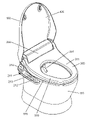
- FIG. 1 is a perspective view showing the appearance of the toilet seat device according to the embodiment of the present disclosure.
- FIG. 2 is a perspective view showing the appearance of the completed state of the toilet seat according to the embodiment of the present disclosure.
- FIG. 3 is a side view of the completed state of the toilet seat in the embodiment of the present disclosure.
- FIG. 4 is a perspective view for explaining the configuration of the parts of the toilet seat according to the embodiment of the present disclosure.
- FIG. 5 is a schematic view showing the lower surface of the toilet seat according to the embodiment of the present disclosure.
- FIG. 6 is a schematic view showing a 6-6 cross section of FIG.
- FIG. 7 is a schematic diagram showing the details of the D portion shown in FIG. FIG.
- FIG. 8A is a schematic view illustrating the contact angle between the surface of the base material and the outer surface of the water droplet.
- FIG. 8B is a schematic diagram illustrating the falling angle of the water droplet on the substrate.
- FIG. 9A is a plan view showing the lower surface of the conventional toilet seat.
- FIG. 9B is a cross-sectional view of a protrusion of a conventional toilet seat.
- the toilet seat according to the example of the embodiment of the present disclosure includes a substantially horizontal main body portion and a support portion inclined diagonally upward from the rear portion of the main body portion in a horizontally installed state.
- the horizontal plane on the substantially flat plate on the lower surface of the main body and the inclined surface on the lower surface of the support are continuously formed.
- the toilet seat according to an example of the embodiment of the present disclosure is a water-repellent treated portion in which convex portions and concave portions are continuously formed so as to form a ridgeline shape from a substantially front end of the horizontal plane to a substantially rear end of the inclined surface. To be equipped with.
- the convex portions are arranged at intervals of 2 ⁇ m or more and 50 ⁇ m or less. Further, in the toilet seat according to the example of the embodiment of the present disclosure, the depth of the recess is formed to be 10 ⁇ m or more.
- the toilet seat according to the example of the embodiment of the present disclosure is preferably configured so that the cross-sectional shape of the convex portion is substantially triangular.
- the water repellency can be further improved.
- the manufacturing cost of the mold can be further reduced, the work of taking out the molded product at the time of molding becomes easy, and the deformation of the molded product can be suppressed.
- the toilet seat according to the example of the embodiment of the present disclosure may be provided with a flat outer peripheral edge on the outer periphery of the water-repellent treated portion and a flat inner peripheral edge on the inner circumference of the water-repellent treated portion.
- the convex portion is preferably configured so as not to protrude from the surfaces of the outer peripheral edge and the inner peripheral edge.
- the toilet seat according to the example of the embodiment of the present disclosure may have a built-in toilet seat heater for heating the main body portion.
- the toilet seat device includes a main body that can be installed on the toilet bowl and a toilet seat that is rotatably supported by the main body according to at least one of the above.
- FIG. 1 is a perspective view showing the appearance of the toilet seat device 100 according to the embodiment of the present disclosure.
- the toilet seat device 100 includes a main body 200 and a toilet seat 300.
- the toilet seat device 100 may include a toilet lid 400.
- the toilet seat device 100 is configured to be installed on the upper surface of the toilet bowl 110.
- the installation side of the main body 200 of the toilet seat device 100 is the rear
- the installation side of the toilet seat 300 is the front
- the right side toward the front is the right side
- the left side toward the front is the left side of each component. The arrangement will be explained.
- the toilet seat 300 and the toilet lid 400 are attached to the main body 200 so as to be openable and closable via a rotation mechanism.
- the toilet lid 400 stands up so as to be located at the rearmost portion of the toilet seat device 100 when the toilet lid 400 is open, and when the toilet lid 400 is closed, the upper surface of the toilet seat 300 is used. And a part of the main body 200 is concealed.
- the toilet seat 300 is configured to stand up from the state of being placed on the upper surface of the toilet bowl 110 on the front surface of the main body 200 like the toilet lid 400.
- the main body 200 includes a cleaning mechanism (not shown), a heat exchanger (not shown), a cleaning mechanism including a cleaning nozzle 201, and a drying unit (not shown). , And a control unit (not shown) are built-in.
- a seating sensor (not shown) for detecting a human body seated on the toilet seat 300 is installed in a bearing portion in the main body 200 that supports the rotation shaft of the toilet seat 300.
- a seating sensor for example, a heavy-weight seating sensor is used.
- the weight-type seating sensor is configured to detect that the user is seated on the toilet seat 300 by opening and closing the switch according to the weight change caused by the user sitting on the toilet seat 300.
- the washing water supply mechanism and the heat exchanger are connected to the washing nozzle 201.
- the washing water supplied from the water pipe is heated by the heat exchanger, and the heated warm washing water is supplied to the washing nozzle 201.
- the washing water is ejected from the cleaning nozzle 201 toward the local part of the user, and the local part of the user is washed by the ejected washing water.
- the cleaning nozzle 201 may include at least one of an ass cleaning nozzle portion for cleaning the buttocks and a bidet nozzle portion for cleaning a female local area.
- the drying unit is configured to blow warm air toward the local area wet with the washing water to dry the local area.
- the cleaning mechanism and the drying unit are not essential components of the toilet seat device 100, and may be a toilet seat device 100 that does not include these components.
- a sleeve portion 210 is provided on the right side of the main body 200 so as to project forward.
- An operation unit 211 is provided on the upper surface of the sleeve portion 210.
- the operation unit 211 is provided with a plurality of operation switches 212 and indicator lights 213 for operating each function of the toilet seat device 100.
- FIG. 2 is a perspective view showing the appearance of the completed toilet seat 300 according to the embodiment of the present disclosure.
- FIG. 3 is a side view of the completed state of the toilet seat 300 according to the embodiment of the present disclosure.
- FIG. 4 is a perspective view for explaining the configuration of the parts of the toilet seat 300 according to the embodiment of the present disclosure.
- FIG. 5 is a schematic view showing the lower surface of the toilet seat according to the embodiment of the present disclosure.
- FIG. 6 is a schematic view showing a 6-6 cross section of FIG.
- the toilet seat 300 has a substantially elliptical ring shape.
- the toilet seat 300 mainly includes a main body portion 301 on which the user sits, and a support portion 302 inclined diagonally upward from the rear portion of the main body portion 301.
- the toilet seat 300 is rotatably supported by the main body 200 via a pivot shaft 303 formed at the rear end of the support portion 302.
- the lower surface of the main body portion 301 of the toilet seat 300 is substantially horizontal, and the lower surface of the support portion 302 is inclined diagonally upward.
- the toilet seat 300 has an upper toilet seat case 310 integrally molded with a resin material mainly made of polypropylene, and a cord heater (shown) on a heat soaking plate made of aluminum foil.
- the toilet seat heater 330 in which the toilet seat heater 330 is arranged and the lower toilet seat case 320 integrally molded of a resin material mainly made of polypropylene are configured as main constituent members.
- the inner and outer peripheral edges of the upper toilet seat case 310 and the lower toilet seat case 320 are joined to each other to form a hollow ring inside.
- the upper toilet seat case 310 is integrally molded by injection molding using a resin material whose main material is polypropylene. Further, the upper toilet seat case 310 is an upper support portion constituting a seat portion 311 constituting a main body portion 301 molded into a substantially elliptical annular shape and a support portion 302 projecting diagonally upward from the rear end portion of the seat portion 311. It is equipped with 312.
- the upper toilet seat case 310 is formed so that the cross section of the seating portion 311 has a substantially mountain shape. Further, the upper surface of the seating portion 311 is formed on a loose curved surface suitable for seating. Further, the inner and outer circumferences of the seating portion 311 are bent downward, and a substantially vertical inner peripheral edge and outer peripheral edge are formed at the tip portion thereof.
- the lower toilet seat case 320 is integrally molded by injection molding using a resin material whose main material is polypropylene.
- the lower toilet seat case 320 is formed into a substantially elliptical annular shape having substantially the same shape as the seating portion 311 of the upper toilet seat case 310.
- the lower toilet seat case 320 includes a lower main body portion 321 and a lower support portion 322.
- the lower support portion 322 has substantially the same shape as the upper support portion 312 of the upper toilet seat case 310, and is formed so as to project diagonally upward from the rear end portion of the lower main body portion 321.
- the inner and outer circumferences of the lower toilet seat case 320 are bent upward, and the inner peripheral edge and the lower outer peripheral edge are formed at the tip portion thereof.
- the inner and outer peripheral edges of the upper toilet seat case 310 and the lower toilet seat case 320 have substantially the same shape, respectively.
- the toilet seat 300 has a continuous appearance shape formed by abutting and connecting the upper toilet seat case 310 and the lower toilet seat case 320, and as shown in FIG. 6, a cavity 304 is formed inside the toilet seat 300. It is configured to be.
- the lower surfaces of the lower main body portion 321 and the lower support portion 322 of the toilet seat 300 are formed in a continuous planar shape.
- a water-repellent treated portion 340 having a substantially linear uneven shape that exhibits water-repellent performance is molded. The details of the water repellent treatment unit 340 will be described later.
- the toilet seat heater 330 has a cord heater covered with a soft vinyl chloride insulating coating at intervals on the surface of a heat soaking plate made of a substantially horseshoe-shaped aluminum foil with a part of the front cut off. It has a structure that is arranged in a meandering manner.
- the toilet seat heater 330 is configured so that the heat generated by the cord heater is conducted to the soaking plate and diffused over the entire surface of the soaking plate.
- the toilet seat heater 330 is adhesively fixed to the inner surface of the upper toilet seat case 310.
- a thermistor which is a temperature detecting means (not shown)
- a thermostat which is a means for preventing overheating, are installed on the surface of the heat soaking plate.
- the cord heater, thermistor and thermostat are connected by lead wires.
- the lower surface of the lower toilet seat case 320 has a horizontal portion 323 corresponding to the lower main body portion 321 and an inclined portion 324 corresponding to the lower support portion 322. Is formed integrally.
- the switching portion 325 between the horizontal portion 323 and the inclined portion 324 is connected by a curved surface arranged substantially linearly behind the lower toilet seat case 320.
- a water repellent treatment portion 340 is formed on substantially the entire surface of the horizontal portion 323 and the inclined portion 324. Further, on the outer circumference and the inner circumference of the water-repellent treated portion 340, flat outer peripheral edges 351 and inner peripheral edges 352 formed in a band shape along the outer peripheral and inner circumferences are formed, respectively (see FIG. 5).
- micrometer-order fine uneven shapes are formed substantially linearly and continuously so as to form a ridgeline from the substantially front end of the horizontal portion 323 to the substantially rear end of the inclined portion 324. More specifically, the water-repellent treatment portion 340 is formed with a convex shape and a groove shape so as to form a ridge line in a direction orthogonal to the switching portion 325.
- FIG. 7 is a schematic diagram showing the details of the D portion shown in FIG.
- the cross-sectional shape of the convex portion 341 of the water repellent treatment portion 340 is substantially triangular, and the bottom portion of the concave portion 342 of the water repellent treatment portion 340 is formed to be substantially flat.
- the convex portions 341 and the concave portions 342 are formed alternately at equal intervals.
- the convex portion 341 is formed in a triangular shape having a height H of about 23 ⁇ m and a base length L of about 18 ⁇ m. Further, the tip portion of the convex portion 341 is formed with a radius R of 1 ⁇ m or less. In the case of a triangular shape having the above dimensions, the tip portion of the convex portion 341 is formed at approximately 45 degrees. The angle of the tip of the convex portion 341 is preferably from about 45 degrees to about 70 degrees. Further, the height H of the convex portion 341 is preferably 10 ⁇ m or more from the viewpoint of water repellency and 50 ⁇ m or less from the viewpoint of strength and the like.
- the width M of the bottom of the recess 342 of the water repellent treatment portion 340 is formed to be approximately 15 ⁇ m.
- These uneven shapes of the water-repellent treated portion 340 are provided so that the pitch N between the tip portions of the adjacent convex portions 341 is approximately 33 ⁇ m.
- the uneven shape is formed over the entire surface of the water-repellent treated portion 340.
- the uneven pitch N is preferably 2 ⁇ m or more and 50 ⁇ m or less.
- the tip portion of the convex portion 341 is arranged at a position not protruding from the surfaces of the outer peripheral edge 351 and the inner peripheral edge 352 adjacent to the water repellent treatment portion 340. With such a configuration, it is possible to obtain an effect of suppressing deformation or breakage of the convex portion 341 during use of the toilet seat 300.
- FIG. 8A is a schematic diagram illustrating the contact angle between the surface of the base material and the outer surface of the water droplet.
- FIG. 8B is a schematic diagram illustrating the falling angle of the water droplet on the substrate.
- the urine or washing water when urine or washing water is applied to the water-repellent treatment section 340 with the toilet seat 300 upright, the urine or washing water becomes small water droplets and slides downward along the unevenness of the water-repellent treatment section 340. It falls into the toilet bowl 110.
- the water repellency As an index for evaluating the water repellency, it is evaluated by a contact angle E as shown in FIG. 8A and a falling angle F as shown in FIG. 8B. That is, it is evaluated that the larger the contact angle E and the smaller the falling angle F, the higher the water repellency.
- the contact angle E is an angle formed by the contact surface of the base material 360 and the outer surface of the water droplets when the water droplets are attached to the surface of the base material 360.
- the fall angle F is an angle at which the base material 360 to which the water droplets are attached is gradually tilted from a horizontal position and the droplets start to slide.
- the contact angle E is about 90 degrees
- the fall angle F is 90 degrees or more.
- the water-repellent treatment unit 340 of the present embodiment can exhibit water-repellent performance with a contact angle E of 150 degrees or more and a falling angle F of 30 degrees or less.
- the water-repellent treated portion 340 of the present embodiment is formed with a fine ridge-shaped uneven shape substantially linearly and continuously from the substantially front end of the horizontal portion 323 to the substantially rear end of the inclined portion 324. With such a configuration, it is possible to unify the drawing direction of the mold at the time of molding. As a result, it is possible to simplify the manufacturing and molding work of the mold, and it is possible to provide the toilet seat 300 having excellent water repellency at low cost.
- the water repellency can be further improved by forming the convex portion so that the cross-sectional shape of the convex portion 341 is substantially triangular. Further, with such a configuration, the manufacturing cost of the mold can be reduced. Further, with such a configuration, the work of taking out the molded product at the time of molding becomes easy, and the deformation of the molded product can be suppressed.
- the water-repellent treated portion 340 of the present embodiment is configured to have a continuous ridge line shape. With such a configuration, when deposits or dirt adhere to the water-repellent treated portion 340, it is easy to clean by wiping. Further, with such a configuration, the effect of suppressing the wear and deformation of the convex portion 341 can be obtained, and the durability can be improved.
- the tip portion of the convex portion 341 of the water repellent treatment portion 340 is configured so as not to protrude from the surfaces of the outer peripheral edge 351 and the inner peripheral edge 352 adjacent to the water repellent treatment portion 340. With such a configuration, it is possible to obtain an effect of suppressing deformation or breakage of the convex portion 341 of the water repellent treatment portion 340 during use of the toilet seat 300.
- the cross-sectional shape of the convex portion 341 is a simple triangle, but the present invention is not limited to this.
- the tip portion is formed to have an acute angle and is opposite to the tip portion.
- the side portion may have a two-step shape formed to have an acute angle.
- the cross-sectional shape of the convex portion 341 is a substantially triangular shape
- the present invention is not limited to this, and a substantially arc shape, a substantially trapezoidal shape, or a shape in which they are combined may be used.
- polypropylene used as the material for the toilet seat 300 is used as the main material, but the present invention is not limited to this, and other resin materials such as ABS resin used for general molded products may also be used. good.
- the present disclosure can be applied to toilet seats and toilet seat devices that can carry out highly durable water repellent treatment at low cost, and further to other applications such as water-related equipment using molded products of resin materials. Is also available.
- Toilet seat device 110 Toilet bowl 200 Main body 201 Cleaning nozzle 210 Sleeve part 211 Operation part 212 Operation switch 213 Indicator light 300 Toilet seat 301 Main body part 302 Support part 303 Pivot shaft 304 Cavity part 310 Upper toilet seat case 311 Seating part 312 Upper support part 320 Lower part Toilet seat case 321 Lower body part 322 Lower support part 323 Horizontal part (horizontal plane) 324 Inclined part (inclined surface) 325 Switching part 330 Toilet seat heater 340 Water repellent treatment part 341 Convex part 342 Concave part 351 Outer peripheral edge 352 Inner peripheral edge 360 Base material
Landscapes
- Health & Medical Sciences (AREA)
- Public Health (AREA)
- Toilet Supplies (AREA)
Priority Applications (2)
| Application Number | Priority Date | Filing Date | Title |
|---|---|---|---|
| CN202180004938.9A CN114828719B (zh) | 2020-11-18 | 2021-06-02 | 便座和具备该便座的便座装置 |
| JP2022511239A JPWO2022107363A1 (https=) | 2020-11-18 | 2021-06-02 |
Applications Claiming Priority (2)
| Application Number | Priority Date | Filing Date | Title |
|---|---|---|---|
| JP2020-191372 | 2020-11-18 | ||
| JP2020191372 | 2020-11-18 |
Publications (1)
| Publication Number | Publication Date |
|---|---|
| WO2022107363A1 true WO2022107363A1 (ja) | 2022-05-27 |
Family
ID=81708692
Family Applications (1)
| Application Number | Title | Priority Date | Filing Date |
|---|---|---|---|
| PCT/JP2021/020995 Ceased WO2022107363A1 (ja) | 2020-11-18 | 2021-06-02 | 便座およびそれを備えた便座装置 |
Country Status (4)
| Country | Link |
|---|---|
| JP (1) | JPWO2022107363A1 (https=) |
| CN (1) | CN114828719B (https=) |
| TW (1) | TW202220604A (https=) |
| WO (1) | WO2022107363A1 (https=) |
Families Citing this family (1)
| Publication number | Priority date | Publication date | Assignee | Title |
|---|---|---|---|---|
| EP4717840A1 (de) * | 2024-09-26 | 2026-04-01 | Hartmut S. Engel | Wc-strahl-waschsystem |
Citations (4)
| Publication number | Priority date | Publication date | Assignee | Title |
|---|---|---|---|---|
| CN205348331U (zh) * | 2015-10-28 | 2016-06-29 | 北京美晟博恩科技有限公司 | 一种防水功能坐便器 |
| JP2017012351A (ja) * | 2015-06-30 | 2017-01-19 | アイシン精機株式会社 | 温水洗浄便座装置 |
| JP2018187350A (ja) * | 2017-04-28 | 2018-11-29 | Toto株式会社 | 便座 |
| JP2019085542A (ja) * | 2017-11-10 | 2019-06-06 | パナソニックIpマネジメント株式会社 | 成形体、家電機器、トイレ用部材、および便座 |
Family Cites Families (2)
| Publication number | Priority date | Publication date | Assignee | Title |
|---|---|---|---|---|
| WO2018128092A1 (ja) * | 2017-01-05 | 2018-07-12 | パナソニックIpマネジメント株式会社 | 成形体 |
| WO2018198667A1 (ja) * | 2017-04-28 | 2018-11-01 | Toto株式会社 | 便座 |
-
2021
- 2021-06-02 CN CN202180004938.9A patent/CN114828719B/zh active Active
- 2021-06-02 JP JP2022511239A patent/JPWO2022107363A1/ja active Pending
- 2021-06-02 WO PCT/JP2021/020995 patent/WO2022107363A1/ja not_active Ceased
- 2021-06-03 TW TW110120266A patent/TW202220604A/zh unknown
Patent Citations (4)
| Publication number | Priority date | Publication date | Assignee | Title |
|---|---|---|---|---|
| JP2017012351A (ja) * | 2015-06-30 | 2017-01-19 | アイシン精機株式会社 | 温水洗浄便座装置 |
| CN205348331U (zh) * | 2015-10-28 | 2016-06-29 | 北京美晟博恩科技有限公司 | 一种防水功能坐便器 |
| JP2018187350A (ja) * | 2017-04-28 | 2018-11-29 | Toto株式会社 | 便座 |
| JP2019085542A (ja) * | 2017-11-10 | 2019-06-06 | パナソニックIpマネジメント株式会社 | 成形体、家電機器、トイレ用部材、および便座 |
Also Published As
| Publication number | Publication date |
|---|---|
| CN114828719A (zh) | 2022-07-29 |
| TW202220604A (zh) | 2022-06-01 |
| CN114828719B (zh) | 2023-07-07 |
| JPWO2022107363A1 (https=) | 2022-05-27 |
Similar Documents
| Publication | Publication Date | Title |
|---|---|---|
| JP3931920B1 (ja) | 衛生洗浄装置及びトイレ装置 | |
| KR20080111455A (ko) | 위생 세정 장치 및 변기 장치 | |
| US7565715B2 (en) | Cleaning implement | |
| WO2022107363A1 (ja) | 便座およびそれを備えた便座装置 | |
| JP6443771B2 (ja) | トイレ装置 | |
| JP5966152B2 (ja) | 暖房便座装置 | |
| CN101548860A (zh) | 卫生清洗装置 | |
| JP7432142B2 (ja) | 便座及び便蓋 | |
| CN111615352A (zh) | 座便装置 | |
| JP4893555B2 (ja) | 洗面化粧台 | |
| CN110714514A (zh) | 卫生清洗装置 | |
| JP5604908B2 (ja) | 交換型便座 | |
| JP7681388B2 (ja) | 便座カバー | |
| JP2009089731A (ja) | 洗面化粧台 | |
| JP7660353B2 (ja) | 便座カバー | |
| JP6845463B2 (ja) | トイレ装置 | |
| JP7122511B2 (ja) | 便座装置 | |
| JP7546436B2 (ja) | 便座カバー | |
| JP7535427B2 (ja) | 便座カバー | |
| JP7643830B2 (ja) | 便座 | |
| JP2007291643A (ja) | 便器 | |
| JP5891432B2 (ja) | 洗面化粧台 | |
| JP2009089730A (ja) | 洗面化粧台 | |
| JP6952553B2 (ja) | 便器 | |
| US499467A (en) | Cleaner for spoons |
Legal Events
| Date | Code | Title | Description |
|---|---|---|---|
| ENP | Entry into the national phase |
Ref document number: 2022511239 Country of ref document: JP Kind code of ref document: A |
|
| 121 | Ep: the epo has been informed by wipo that ep was designated in this application |
Ref document number: 21894240 Country of ref document: EP Kind code of ref document: A1 |
|
| NENP | Non-entry into the national phase |
Ref country code: DE |
|
| 122 | Ep: pct application non-entry in european phase |
Ref document number: 21894240 Country of ref document: EP Kind code of ref document: A1 |