WO2022102775A1 - センシング装置、車両用灯具、車両 - Google Patents
センシング装置、車両用灯具、車両 Download PDFInfo
- Publication number
- WO2022102775A1 WO2022102775A1 PCT/JP2021/041926 JP2021041926W WO2022102775A1 WO 2022102775 A1 WO2022102775 A1 WO 2022102775A1 JP 2021041926 W JP2021041926 W JP 2021041926W WO 2022102775 A1 WO2022102775 A1 WO 2022102775A1
- Authority
- WO
- WIPO (PCT)
- Prior art keywords
- cell
- cells
- light receiving
- sensing device
- light
- Prior art date
- Legal status (The legal status is an assumption and is not a legal conclusion. Google has not performed a legal analysis and makes no representation as to the accuracy of the status listed.)
- Ceased
Links
Images






Classifications
-
- G—PHYSICS
- G01—MEASURING; TESTING
- G01S—RADIO DIRECTION-FINDING; RADIO NAVIGATION; DETERMINING DISTANCE OR VELOCITY BY USE OF RADIO WAVES; LOCATING OR PRESENCE-DETECTING BY USE OF THE REFLECTION OR RERADIATION OF RADIO WAVES; ANALOGOUS ARRANGEMENTS USING OTHER WAVES
- G01S17/00—Systems using the reflection or reradiation of electromagnetic waves other than radio waves, e.g. lidar systems
- G01S17/86—Combinations of lidar systems with systems other than lidar, radar or sonar, e.g. with direction finders
-
- G—PHYSICS
- G01—MEASURING; TESTING
- G01S—RADIO DIRECTION-FINDING; RADIO NAVIGATION; DETERMINING DISTANCE OR VELOCITY BY USE OF RADIO WAVES; LOCATING OR PRESENCE-DETECTING BY USE OF THE REFLECTION OR RERADIATION OF RADIO WAVES; ANALOGOUS ARRANGEMENTS USING OTHER WAVES
- G01S17/00—Systems using the reflection or reradiation of electromagnetic waves other than radio waves, e.g. lidar systems
- G01S17/88—Lidar systems specially adapted for specific applications
- G01S17/93—Lidar systems specially adapted for specific applications for anti-collision purposes
- G01S17/931—Lidar systems specially adapted for specific applications for anti-collision purposes of land vehicles
Definitions
- This disclosure relates to a sensing device.
- an object identification system that senses the position and type of objects existing around the vehicle.
- the object identification system includes a sensor and an arithmetic processing device that analyzes the output of the sensor.
- the sensor is selected from among cameras, LiDAR (Light Detection and Ranging, Laser Imaging Detection and Ranging), millimeter-wave radar, ultrasonic sonar, etc. in consideration of application, required accuracy, and cost.
- ADAS advanced driver-assistance systems
- millimeter-wave radar and camera were the main sensing devices, but in the level 4 or higher automatic driving system, the city area.
- LiDAR is regarded as promising because it is necessary to detect and identify various objects existing in the system.
- the point cloud data generated by LiDAR includes not only the shape of the object but also the distance information to the object, but the resolution is lower than that of a general camera.
- the present disclosure has been made in such circumstances, and one of the exemplary purposes of that aspect is to provide a sensing device capable of obtaining more information.
- the sensing device of one aspect of the present disclosure includes a lighting device capable of irradiating a plurality of cells having a divided field of view with spatially patterned illumination light, and a plurality of light receiving elements corresponding to the plurality of cells. It includes a light receiving element array and an arithmetic processing device that generates distance information for each of a plurality of cells based on the ToF (flight time) method and also generates image data of the plurality of cells based on the correlation method.
- a lighting device capable of irradiating a plurality of cells having a divided field of view with spatially patterned illumination light, and a plurality of light receiving elements corresponding to the plurality of cells. It includes a light receiving element array and an arithmetic processing device that generates distance information for each of a plurality of cells based on the ToF (flight time) method and also generates image data of the plurality of cells based on the correlation method.
- ToF light time
- the sensing device of one aspect of the present disclosure includes a lighting device capable of irradiating each of a plurality of N (N ⁇ 2) cells having a divided field of view with spatially patterned illumination light, and a binary value of each.
- a light receiving element array including K (K ⁇ 2) ⁇ N light receiving elements for outputting a detection signal and K light receiving elements assigned to each of a plurality of N cells, and (i) ToF ( By the (flight time) method, distance information is generated for each of the plurality of N cells based on the output of at least one of the K light receiving elements corresponding to each cell, and (ii) for each of the plurality of N cells. It is provided with an arithmetic processing device that generates a multi-valued detection intensity based on the outputs of K light receiving elements corresponding to each cell and generates image data of each cell by a correlation method.
- This device corresponds to a lighting device capable of irradiating spatially patterned illumination light to each of a plurality of N cells (N ⁇ 2) having a divided field, and a plurality of N cells, each of which corresponds to a plurality of cells.
- a light receiving element array containing a plurality of N light receiving elements that output a binary detection signal, and (i) for each of the plurality of N cells, based on the detection signal output by the corresponding one of the N light receiving elements.
- a histogram with the distance as a class is generated, the distance information of each cell is generated based on the histogram, and (ii) the detection intensity is generated based on the histogram, and the detection intensity is used. It is provided with an arithmetic processing device that generates image data of each cell by the above-mentioned correlation method.
- distance information and image information can be obtained.
- FIG. 9 (a) is a time chart of distance measurement by the sensing device of FIG. 7, and FIG. 9 (b) is a histogram in which the distance is a class.
- FIG. 1 It is a figure explaining the generation of the histogram which concerns on the modification 1. It is a figure explaining the generation of the histogram which concerns on the modification 2. It is a time chart of the generation of one image data in the sensing apparatus of FIG. It is a figure which shows the sensing apparatus which concerns on Embodiment 3.
- FIG. It is a figure which shows the relationship between the histogram HIST ij and the detection intensity bij .
- the sensing device is a light receiving device including a lighting device capable of irradiating a plurality of cells having a divided field of view with spatially patterned illumination light and a plurality of light receiving elements corresponding to the plurality of cells. It includes an element array and an arithmetic processing device that generates distance information for each of a plurality of cells based on the ToF (flight time) method and also generates image data of the plurality of cells based on the correlation method.
- ToF light time
- the image information for each cell can be acquired.
- the illuminating device may sequentially irradiate each cell with a plurality of illuminating lights having a random intensity distribution.
- the arithmetic processing apparatus may acquire the distance information of the corresponding cell by the ToF method based on the output of each light receiving element, and may generate the image data of the corresponding cell by the correlation method. As a result, both distance information and image information can be obtained by one operation of the lighting device.
- the lighting device may sequentially irradiate each cell with a plurality of illumination lights having a random intensity distribution.
- the illuminating device may irradiate each cell with uniform illumination light.
- the illuminating device may irradiate a part of each cell with the illuminating light.
- the sensing device is a lighting device capable of irradiating each of a plurality of N cells (N ⁇ 2) having a divided field of view with spatially patterned illumination light, and detection of binary values for each.
- a light receiving element array that includes K (K ⁇ 2) ⁇ N light receiving elements that output signals and K light receiving elements are assigned to each of a plurality of N cells, and (i) ToF (flying).
- ToF ToF
- distance information can be acquired for each of a plurality of cells. Further, the outputs of a plurality of K binary sensors can be multivalued, and the image data can be restored by the correlation calculation based on the multivalued detection intensity.
- the lighting device when generating image data by the correlation method, may sequentially irradiate a region including K cells with a plurality of illumination lights having a random intensity distribution.
- the illuminating device may irradiate each cell with uniform illumination light.
- the lighting device may irradiate a part of each cell with illumination light when generating distance information by the ToF method.
- the distance information generated by the ToF method may be generated by using a plurality of illumination lights generated by the lighting device when the image data is generated by the correlation method.
- the sensing device includes a lighting device capable of irradiating spatially patterned illumination light to each of a plurality of N cells (N ⁇ 2) having a divided field of view, and a plurality of N cells.
- Corresponding light receiving element arrays including multiple N light receiving elements, each of which outputs a binary detection signal, and (i) detection of each of the plurality of N cells, output by the corresponding one of the N light receiving elements.
- the ToF (flight time) method is used to generate a histogram with the distance as a class, the distance information of each cell is generated based on the histogram, and (ii) the detection intensity is generated based on the histogram. It is provided with an arithmetic processing device that generates image data of each cell by a correlation method using the detection intensity.
- image data can be generated while performing distance measurement.
- the arithmetic processing apparatus may use the frequency at the mode of the histogram as the detection intensity.
- the intensity distribution is random in the present specification does not mean that it is completely random, but it may be random enough to reconstruct an image in ghost imaging. Therefore, “random” in the present specification can include some regularity in it. Also, “random” does not require to be completely unpredictable, but may be predictable and reproducible.
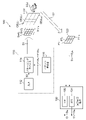
- FIG. 1 is a diagram showing a sensing device 100 according to the first embodiment.
- the sensing device 100 includes a lighting device 110, a light receiving element array 120, and an arithmetic processing device 130.
- the sensing device 100 divides the visual field FOV into a plurality of N cells CELL 1 to CELL N and performs sensing.
- the lighting device 110 is configured to be capable of irradiating a spatially patterned illumination light Sref 1 to Sref N to each of a plurality of cells CELL 1 to CELL N having a divided visual field FOV. Patterning also includes a uniform intensity distribution.
- the visual field FOV is divided into matrix-shaped cells CELL 1 to CELL N having 3 rows ⁇ 4 columns, and the number N of cells is 12.
- the number N and arrangement of the plurality of cells are not limited thereto.
- the illumination lights Sref 1 to Sref N may be irradiated at the same time or may be irradiated in a time-division manner, but in the following, they are simultaneously irradiated.
- the lighting device 110 includes a light source 112, a patterning device 114, and a pattern generator 116.
- An optical system such as a floodlight lens (collimating lens) or a mirror is provided at the emission end of the lighting device 110, but the illustration is omitted.
- the light source 112 produces a light beam S0 having a uniform intensity distribution.
- a laser, a light emitting diode, or the like may be used as the light source 112.
- the wavelength and spectrum of the illumination light Sref are not particularly limited, but are infrared in the present embodiment.
- the patterning device 114 has a plurality of pixels arranged in a matrix, and is configured so that the light intensity distribution I (x, y) can be spatially modulated based on a combination of on and off of the plurality of pixels.
- the pixel in the on state is referred to as an on pixel
- the pixel in the off state is referred to as an off pixel.
- each pixel takes only two values (1,0) of on and off, but it is not limited to this, and an intermediate gradation may be taken.
- An optical system including a lens or the like may be inserted between the patterning device 114 and the light source 112.
- the patterning device 114 As the patterning device 114, a reflective DMD (Digital Micromirror Device) or a transmissive liquid crystal device can be used.
- the patterning device 114 is provided with patterning data PTN (image data) generated by the pattern generator 116.
- the pattern generator 116 may be mounted inside the arithmetic processing apparatus 130.
- the light receiving element array 120 includes a plurality of light receiving elements (phototransducer) PT 1 to PTN corresponding to the plurality of cells CELL 1 to CELL N.
- the structure and type of the light receiving element PT are not particularly limited, but a photodiode, a photomultiplier tube, a photoelectric guide element, and the like can be used. Further, an optical system including a condenser lens and the like is arranged on the front surface of the light receiving element array 120, but the illustration is omitted.
- Each light receiving element PT has sensitivity to the same wavelength as the illumination light S1 generated by the illumination device 110.
- the i -th light receiving element PT i receives the light from the corresponding cell CELL i , more specifically, the reflected light reflected by the object OBJ existing in the cell CELL i , and is increased according to the amount of light. Generates a value or analog detection signal.
- Each light receiving element PT constituting the light receiving element array 120 may be a photodetector (photodetector).
- the arithmetic processing apparatus 130 receives the output of the light receiving element array 120, that is, the detection signals Sp 1 to Sp N of the plurality of light receiving elements PT 1 to PT N.
- the arithmetic processing apparatus 130 includes a ToF processing unit 132 and an SPI (Single Pixel Imaging) processing unit 134.
- the ToF processing unit 132 calculates the distance information for each of the plurality of cells CELL 1 to CELL N. Specifically, the ToF processing unit 132 has distance information to the cell CELL corresponding to the light receiving element PT i based on the detection signal Sp i which is the output of the i-th (1 ⁇ i ⁇ N) light receiving element PT i . Is obtained by the ToF method. For example, the ToF processing unit 132 acquires the delay time ⁇ i from the irradiation start time of the illumination light Sref i by the lighting device 110 until the corresponding detection signal Spi changes, and sets the delay time ⁇ i as the distance information Di. do. From the arithmetic processing device 130, distance information D 1 to DN of each of the plurality of cells CELL 1 to CELL N is output. This set of distance information D 1 to DN can be regarded as corresponding to the point cloud data in LiDAR.
- the SPI processing unit 134 calculates image data Gi (x, y ) for each of the plurality of cells CELL 1 to CELL N.
- the SPI processing unit 134 is based on the detection signal Sp i which is the output of the i-th light receiving element PT i , and the image data (also referred to as a restored image ) of the cell CELL i corresponding to the light receiving element PT i (x, y) is acquired based on the correlation method (also referred to as single pixel imaging).
- the lighting device 110 sequentially irradiates M random patterns PTN i1 to PTN iM with respect to the i-th (1 ⁇ i ⁇ N) cell CELL i .
- the j-th (1 ⁇ j ⁇ M) patterns PTN 1j to PTN Nj irradiated to a plurality of cells CELL 1 to CELL N may be the same or different.
- the detection signal Sp i obtained while irradiating the j-th random pattern PTN ij is referred to as Sp i j .
- the arithmetic processing apparatus 130 acquires the detection intensity bij according to the detection signal Spij .
- the detection signal Spij is sampled only once during the irradiation of one pattern, the value may be set as the detection intensity bij .
- the average value of the plurality of sampling values may be the detection intensity bij , or some of the total sampling values may be selected.
- the integrated value, the average value, and the maximum value of the selected sampling values may be used.
- the xth to yth ranks may be extracted counting from the maximum value, digital values lower than an arbitrary threshold value may be excluded, and the magnitude of signal fluctuation may be excluded. Sampling values in a small range may be extracted.
- M detection intensities bi1 to biM When M random patterns are irradiated, M detection intensities bi1 to biM can be obtained.
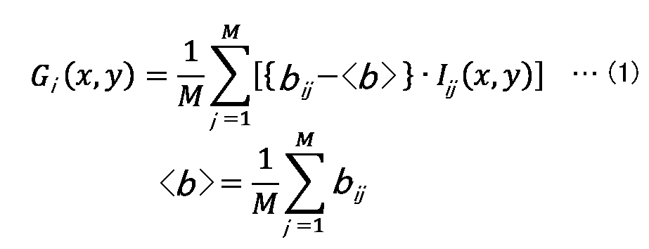
- the arithmetic processing device 130 performs a correlation calculation between M detection intensities bi1 to biM and M patterning data PTN i1 to PTN iM , and generates a restored image Gi (x, y ) of the cell CELL i . ..
- I ij is the intensity distribution of the j-th illumination light Sref ij , that is, the random pattern PTN ij , which is applied to the i-th cell CELL i .
- the arithmetic processing apparatus 130 may output the images G1 to GN of each of the plurality of cells CELL 1 to CELL N individually, or combine them and output them as one image of the entire cell. May be good.
- the plurality of cells CELL are a matrix of horizontal u ⁇ vertical v and the resolution of the pattern PTN is X ⁇ Y
- the resolution of the final image is horizontal X ⁇ u and vertical Y ⁇ v.
- the arithmetic processing unit 130 can be implemented by combining a processor (hardware) such as a CPU (Central Processing Unit), an MPU (Micro Processing Unit), or a microcontroller, and a software program executed by the processor (hardware).
- a processor such as a CPU (Central Processing Unit), an MPU (Micro Processing Unit), or a microcontroller
- the arithmetic processing unit 130 may be a combination of a plurality of processors. Alternatively, the arithmetic processing apparatus 130 may be configured only by hardware.
- the above is the configuration of the sensing device 100. Next, the operation will be described.
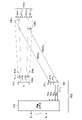
- FIG. 2 is a diagram illustrating distance measurement in the sensing device 100 of FIG.
- set N 4 and focus on the four cells CELL 1 to CELL 4 .
- the lighting device 110 irradiates each of the plurality of cells CELL 1 to CELL 4 with illumination lights Sref 1 to Sref 4 for distance measurement.
- the illumination lights Sref 1 to Sref 4 at this time may also serve as illumination light for generating image data, or may be other light dedicated to distance measurement. In the case of light dedicated to distance measurement, the intensity distribution of each of the illumination lights Sref 1 to Sref 4 can be made uniform.
- the delay time ⁇ i until the change is set with c as the speed of light.
- ⁇ i 2 ⁇ di / c Will be. That is, the delay time ⁇ i is proportional to the distance di .
- the arithmetic processing apparatus 130 can obtain the distance information Di indicating the distance di by acquiring the delay time ⁇ i from the light emission timing to the change of the detection signal Spi.
- the method for measuring the delay time ⁇ is not particularly limited.
- the detection signal Spi when the detection signal Spi is output at a predetermined sampling rate (or a predetermined frame rate as one pixel of image data), the detection signal Spi changes at which sampling from the light emission of the lighting device 110. Depending on what you did, you can get the delay time ⁇ i .
- the delay time ⁇ i may be measured by using a timer resource.
- distance information D 1 to DN indicating the distances d 1 to d N to the objects existing in the plurality of cells CELL 1 to CELL N can be obtained. That is, N point cloud data can be obtained by the sensing device 100.
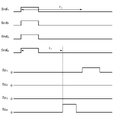
- FIG. 3 is a time chart of distance measurement by the sensing device 100 of FIG.
- the plurality of illumination lights Sref 1 to Sref 4 may be emitted at the same time as shown in FIG.
- a plurality of illumination lights Sref 1 to Sref 4 may be emitted in a time-division manner.
- the distance may be measured by simultaneously irradiating each row.
- the distance may be measured by simultaneously irradiating each row.
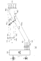
- FIG. 4 is a diagram illustrating the generation of image data in the sensing device 100 of FIG.
- the illumination light Sref i irradiated to each cell CELL i is randomly patterned at a resolution of XY, and M patterns PTN i1 to PTN iM are sequentially patterned. Can be switched.
- the detection intensity bij based on the output Sp ij of the corresponding light receiving element PT i when the j-th pattern PTN ij is irradiated depends on the pattern PTN ij , the shape of the object OBJ i , and the reflectance of each part.
- the arithmetic processing device 130 calculates the correlation between the M detection intensities bi 1 to bi M obtained for the cell CELL i and the intensity distributions I i 1 (x, y) to I i M (x, y) of the corresponding patterns. Based on this, the image data Gi (x, y ) is restored. The resolution of the image data Gi (x, y ) is equal to the resolution of the pattern PTN.
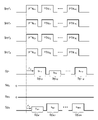
- FIG. 5 is a time chart for generating image data G1 to GN in the sensing device 100 of FIG.
- the spatial intensity distribution of the illumination light Sref i applied to the cell CELL i is sequentially modulated by M patterns PTN i1 to PTN iM .
- the output Sp i of the light receiving element PT i indicates the intensity of the reflected light from the object OBJ i existing in the cell CELL i , and changes every time the pattern PTN ij is switched.
- the detection signal Sp i changes to Sp i1 , Sp i 2, ... Sp iM corresponding to a plurality of patterns PTN i1 to PTN iM , and a plurality of detection intensities bi1 to biM are generated . ..
- the image data Gi (x, y ) is restored by using the plurality of detection intensities bi1 to biM thus obtained.
- FIG. 6 is a time chart for generating image data based on the correlation method.
- FIG. 6 shows image restoration of one cell CELL. Illumination light Sref having M random intensity distributions I 1 to IM is sequentially irradiated to generate an image of one frame. In FIG. 6, the illumination light is patterned with a resolution of 4 ⁇ 4. Then, the detection intensity b is generated for each intensity distribution, and the correlation calculation is performed.
- the above is the configuration of the sensing device 100. According to this sensing device 100, it is possible to obtain distance information of a point cloud corresponding to a plurality of cells CELL 1 to CELL N , and it is possible to operate as a LiDAR.
- a plurality of cells CELL 1 to CELL N are arranged in a matrix, but they may be arranged in a one-dimensional manner in the horizontal direction in one row and N columns.
- Image data generation and distance measurement may be performed separately, but distance measurement may be performed at the same time as image data generation.
- the delay time ⁇ i of the timing at which the output Sp ij of the light receiving element PT i changes and the emission timing of the corresponding illumination light Sref ij is proportional to the distance di to the object OBJ i . Therefore, the delay time may be measured and the distance may be acquired by using the patterned illumination light for generating the image data.
- the lighting device 110 is composed of a combination of the light source 112 and the patterning device 114, but the present invention is not limited to this.
- the lighting device 110 is composed of an array of a plurality of semiconductor light sources (LED (light emitting diode) and LD (laser diode)) arranged in a matrix, and can control on / off (or brightness) of each semiconductor light source. It may be configured as.
- the lighting device 110 may irradiate a part of each cell (for example, only the center) in a spot shape.
- a method using correlation calculation has been described as a method of ghost imaging (or single pixel imaging), but the method of image reconstruction is not limited thereto.
- an analytical method using Fourier transform or Hadamard transform instead of correlation calculation, a method for solving an optimization problem such as sparse modeling, and an algorithm using AI / machine learning are used. The image may be reconstructed.
- FIG. 7 is a diagram showing a sensing device 100A according to the second embodiment.
- the sensing device 100A divides the visual field FOV into a plurality of N cells CELL 1 to CELL N and performs sensing.
- the sensing device 100A includes a lighting device 110, a light receiving element array 120A, and an arithmetic processing device 130A.
- the lighting device 110 is configured to be capable of irradiating spatially patterned illumination lights Sref 1 to Sref N to each of a plurality of N cells CELL 1 to CELL N having a divided visual field FOV. Patterning also includes a uniform intensity distribution.
- the visual field FOV is divided into matrix-shaped cells CELL 1 to CELL N having 6 rows ⁇ 8 columns, and the number N of cells is 48, but in reality, the number N of cells is It may be hundreds to millions.
- the number N and arrangement of the plurality of cells are not limited thereto.
- the illumination lights Sref 1 to Sref N may be irradiated at the same time or may be irradiated in a time-division manner, but in the following, they are simultaneously irradiated.
- the lighting device 110 includes a light source 112, a patterning device 114, and a pattern generator 116.
- An optical system such as a floodlight lens (collimating lens) or a mirror is provided at the emission end of the lighting device 110, but the illustration is omitted.
- the light source 112 produces a light beam S0 having a uniform intensity distribution.
- a laser, a light emitting diode, or the like may be used as the light source 112.
- the wavelength and spectrum of the illumination light Sref are not particularly limited, but are infrared in the present embodiment.
- the patterning device 114 has a plurality of pixels arranged in a matrix, and is configured so that the light intensity distribution I (x, y) can be spatially modulated based on a combination of on and off of the plurality of pixels.
- the pixel in the on state is referred to as an on pixel
- the pixel in the off state is referred to as an off pixel.
- each pixel takes only two values (1,0) of on and off, but it is not limited to this, and an intermediate gradation may be taken.
- An optical system including a lens or the like may be inserted between the patterning device 114 and the light source 112.
- the patterning device 114 As the patterning device 114, a reflective DMD (Digital Micromirror Device) or a transmissive liquid crystal device can be used.
- the patterning device 114 is provided with patterning data PTN (image data) generated by the pattern generator 116.
- the pattern generator 116 generates patterning data PTN i that specifies the intensity distribution I i of the illumination light Sref i .
- the pattern generator 116 may be mounted inside the arithmetic processing apparatus 130A.
- the light receiving element array 120A includes a plurality of N ⁇ K light receiving elements (phototransducer) PT 11 ... PT 1K , PT 21 ... PT 2K , ..., PT N1 ... PT NK . However, K ⁇ 2.
- the light receiving element PT outputs a binary detection signal and has sensitivity to the same wavelength as the illumination light S1 generated by the illumination device 110.
- the structure and type of the light receiving element PT are not particularly limited, but SPAD (Single Photon Avalanche Diode) is suitable, and therefore the light receiving element array 120A can be a SPAD image sensor.
- SPAD image sensor a sensor having several hundred thousand pixels to one million pixels is commercially available.
- an optical system including a condenser lens and the like is arranged on the front surface of the light receiving element array 120, but the illustration is omitted.
- K light receiving elements PTs are assigned to each of the plurality of N cells CELLs.
- the K light receiving elements PT i1 to PT iK corresponding to one cell CELL i reflect the light from the corresponding cell CELL i , more specifically, the object OBJ existing in the cell CELL i reflects the illumination light Sref i .
- the reflected light Sback i is received, and the detection signals Sp i1 to Sp iK , which are 1 or 0, are output based on the photon detection probability of the light receiving element.
- K 4.
- the arithmetic processing apparatus 130A is the output of the light receiving element array 120A, that is, the detection signals Sp 11 to Sp 1K, Sp 21 to a plurality of light receiving elements PT 11 to PT 1K , PT 21 to PT 2K, ..., PT N1 to PT NK . Receive Sp 2K, ..., Sp N1 to Sp NK .
- the arithmetic processing apparatus 130A includes a ToF processing unit 132 and an SPI (Single Pixel Imaging) processing unit 134.
- the ToF processing unit 132 calculates the distance information for each of the plurality of cells CELL 1 to CELL N. Specifically, the ToF processing unit 132 is one or a plurality of detection signals Sp i1 to Sp iK which are outputs of K light receiving elements PT i1 to PT iK corresponding to the i-th (1 ⁇ i ⁇ N) cell. Based on this, the distance information to the cell CELL i is acquired by the ToF method.
- the ToF processing unit 132 acquires the delay time ⁇ i until one or more of the corresponding detection signals Sp i1 to Sp iK change from the irradiation timing of the illumination light Sref i by the lighting device 110, and the delay time ⁇ i .
- the distance information Di is generated based on this. From the arithmetic processing device 130A, the distance information D 1 to DN of each of the plurality of cells CELL 1 to CELL N is output. This set of distance information D 1 to DN can be regarded as corresponding to the point cloud data in LiDAR.
- the SPI processing unit 134 calculates image data G 1 (x, y ) to GN (x, y) for each of the plurality of cells CELL 1 to CELL N.
- the SPI processing unit 134 outputs the K light receiving elements PT i1 to PT iK corresponding to the cell CELL i Sp i1 to Sp iK . Based on this, a multi-valued detection intensity bi is generated. Then, the image data Gi (x, y ) is generated by the correlation method (also referred to as single pixel imaging ) using the detection intensity bi. That is, when x out of K Sp i1 to Sp iK become 1 in a predetermined time window after irradiation with the illumination light Sref i , the value of the detection intensity bi is defined as x. x can take 0 to K.
- the lighting device 110 sequentially irradiates M random patterns PTN i1 to PTN iM with respect to the i-th (1 ⁇ i ⁇ N) cell CELL i .
- the j-th (1 ⁇ j ⁇ M) patterns PTN 1j to PTN Nj irradiated to a plurality of cells CELL 1 to CELL N may be the same or different.
- the arithmetic processing device 130A performs a correlation calculation between M detection intensities bi1 to biM and M patterning data PTN i1 to PTN iM , and generates a restored image Gi (x, y ) of the cell CELL i . ..
- I ij is the intensity distribution of the j-th illumination light Sref ij , that is, the random pattern PTN ij , which is applied to the i-th cell CELL i .
- the arithmetic processing apparatus 130A may output the image data G1 to GN of each of the plurality of cells CELL 1 to CELL N individually, or combine them and output them as one image of the entire visual field FOV. You may.
- the plurality of cells CELL are a matrix of horizontal u ⁇ vertical v and the resolution of the pattern PTN is X ⁇ Y, the resolution of the final image is horizontal X ⁇ u and vertical Y ⁇ v.
- the arithmetic processing unit 130A can be implemented by combining a processor (hardware) such as a CPU (Central Processing Unit), an MPU (Micro Processing Unit), or a microcontroller, and a software program executed by the processor (hardware).
- a processor such as a CPU (Central Processing Unit), an MPU (Micro Processing Unit), or a microcontroller
- the arithmetic processing unit 130A may be a combination of a plurality of processors.
- the arithmetic processing device 130A may be configured by only hardware.
- the above is the configuration of the sensing device 100A. Next, the operation will be described.
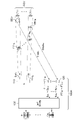
- FIG. 8 is a diagram illustrating distance measurement in the sensing device 100A of FIG. 7.
- the lighting device 110 irradiates each of the plurality of cells CELL 1 to CELL N with illumination light Sref 1 to Sref N for distance measurement.
- the illumination lights Sref 1 to Sref N at this time may also serve as illumination light for generating image data, or may be other light dedicated to distance measurement. In the case of light dedicated to distance measurement, the intensity distribution of each of the illumination lights Sref 1 to Sref N can be made uniform.
- the arithmetic processing apparatus 130A can obtain the distance information Di indicating the round trip time Tdi and thus the distance di by acquiring the delay time ⁇ ij from the emission timing of the illumination light Sref i to the change of the detection signal Sp ij . can.
- the method for measuring the delay time ⁇ is not particularly limited.
- the detection signal Spij when the detection signal Spij is output at a predetermined sampling rate (or a predetermined frame rate as one pixel of image data), the detection signal Spij changes at the sampling number from the light emission of the lighting device 110. Depending on what you did, you can get the delay time ⁇ i .
- the delay time ⁇ ij may be measured by using a timer resource.
- One cell CELL corresponds to a point in LiDAR with SPAD. Similar to LiDAR using SPAD, in the distance measurement of one cell CELL i , the illumination light Sref i is irradiated multiple times, the delay time ⁇ ij is measured for each irradiation, and the delay time ⁇ ij , that is, the distance idi. It is possible to generate a histogram with the class as, and to generate the distance information Di based on the histogram. For example, the mode value of the histogram may be used as distance information, or the average value of the histogram may be used as distance information.
- distance information D 1 to DN indicating the distances d 1 to d N to the objects existing in the plurality of cells CELL 1 to CELL N can be obtained. That is, N point cloud data can be obtained by the sensing device 100A.
- FIG. 9 (a) is a time chart of distance measurement by the sensing device 100A of FIG. 7, and FIG. 9 (b) is a histogram in which the distance is a class. Only one of the K light receiving elements PT i1 to PT iK may be used to generate the histogram. That is, only one of the K detection signals Sp i1 to Sp iK may be monitored, and the delay time ⁇ ij of one detection signal Sp ij may be measured a plurality of times to generate a histogram.
- the lighting device 110 repeatedly irradiates the illumination light Sref i .
- the output Sp i1 of the light receiving element PTi i1 responds only to the return light Sback i , and the delay time ⁇ i1 coincides with the round trip time Tdi .
- the detection signal Sp may behave statistically due to the influence of disturbance, and may change at a timing different from the light reception timing of the return light Sback i . Therefore, in order to obtain the round trip time Tdi, it is necessary to statistically process the delay time ⁇ i1 .
- the arithmetic processing device 130A repeatedly measures the time ⁇ i1 from the light emission to the change of the detection signal Spi 1 , and generates a histogram having the time ⁇ i1 (in other words, the distance) as a class. Then, as shown in FIG. 9B, the mode value of this histogram is acquired as the delay time ⁇ i according to the actual distance, that is, the round trip time Tdi .
- the average value may be used instead of the mode value.
- FIG. 10 is a diagram illustrating the generation of the histogram according to the first modification.
- all of K light receiving elements PT i1 to PT iK may be used to generate the histogram. That is, the delay times ⁇ i1 to ⁇ iK of each of the K detection signals Sp i1 to Sp iK may be measured a plurality of times to generate a histogram.
- FIG. 11 is a diagram illustrating the generation of the histogram according to the modified example 2.
- all of K light receiving elements PT i1 to PT iK may be used to generate the histogram.
- a histogram may be generated by monitoring K detection signals Sp i1 to Sp iK and measuring the delay time ⁇ i multiple times with the time until a predetermined number of them change as the delay time ⁇ i . .. In FIG. 11, the time until the two detection signals change is defined as the delay time ⁇ i .
- the accuracy of the time measurement can be improved.
- a plurality of illumination lights Sref 1 to Sref N may be emitted at the same time.
- a plurality of illumination lights Sref 1 to Sref N may be emitted in a time-division manner.
- the distance may be measured by simultaneously irradiating each row. Alternatively, the distance may be measured by simultaneously irradiating each row.
- FIG. 11 is a diagram illustrating the generation of image data in the sensing device 100A of FIG. 7. As described above, the image data is generated cell by cell.
- the illumination light Sref i irradiated to each cell CELL i is randomly patterned at a resolution of XY, and M patterns PTN i1 to PTN iM are sequentially patterned. Can be switched.
- the detection intensity bi based on the outputs Sp i1 to Sp iK of the corresponding light receiving elements PT i1 to PT iK when the j -th pattern PTN ij is irradiated is referred to as bij .
- the detection intensity bij is the number of detection signals Sp i1 to Sp iK having a value of 1 when the j-th pattern PTN ij is irradiated.
- the arithmetic processing apparatus 130A has a detection intensity bi1 to biM obtained as a result of irradiation of M patterns with respect to the cell CELL i , and an intensity distribution Ii1 (x, y) to IiM (x,,) of the corresponding patterns.
- the image data Gi (x, y ) is restored based on the correlation calculation with y).
- the resolution of the image data Gi (x, y ) is equal to the resolution of the pattern PTN.
- FIG. 12 is a time chart for generating one image data Gi in the sensing device 100A of FIG. 7.
- the spatial intensity distribution of the illumination light Sref i applied to the cell CELL i is sequentially modulated by M patterns PTN i1 to PTN iM .
- the detection signals Sp i1 to Sp iK which are the outputs of the K light receiving elements PT i1 to PT iK , respond to the reflected light from the object OBJ i existing in the cell CELL i , and are based on the detection signals Sp i1 to Sp iK . Therefore, a multi-valued detection intensity bi is generated.
- one pattern PTN ij may be irradiated for a long time to some extent, and the detection signals Sp i1 to Sp ik may be sampled a plurality of times during that time to generate a detection intensity bij .
- the above is the configuration of the sensing device 100A. According to this sensing device 100A, it is possible to obtain distance information of a point cloud corresponding to a plurality of cells CELL 1 to CELL N , and it can be operated as LiDAR.
- the image data generation and the distance measurement may be performed separately, but the distance measurement may be performed at the same time as the image data generation.
- the delay time ⁇ i of the timing at which the output Sp ij of the light receiving element PT i changes and the emission timing of the corresponding illumination light Sref ij is proportional to the distance di to the object OBJ i . Therefore, the delay time may be measured and the distance may be acquired by using the patterned illumination light for generating the image data.
- FIG. 13 is a diagram showing a sensing device 100B according to the third embodiment.
- the sensing device 100B divides the visual field FOV into a plurality of N cells CELL 1 to CELL N and performs sensing.
- the sensing device 100B includes a lighting device 110, a light receiving element array 120B, and an arithmetic processing device 130B.
- the lighting device 110 is configured to be capable of irradiating spatially patterned illumination lights Sref 1 to Sref N to each of a plurality of N cells CELL 1 to CELL N having a divided visual field FOV.
- the light receiving element array 120B includes a plurality of N light receiving elements PT 1 to PTN.
- the light receiving element PT outputs a binary detection signal as in the second embodiment, and has sensitivity to the same wavelength as the illumination light S1 generated by the illumination device 110.
- One of the N light receiving elements PT 1 to PT N , PT i receives the reflected light Sback i in which the object OBJ existing in the corresponding cell CELL i reflects the illumination light Sref i , and 1 based on the photon detection probability. Or, the detection signal Spi of 0 is output.
- the arithmetic processing apparatus 130B receives the output of the light receiving element array 120B, that is, a plurality of detection signals Sp 1 to Sp N.
- the arithmetic processing apparatus 130B includes a ToF processing unit 132 and a GI (Ghost Imaging) processing unit 134.
- the lighting device 110 sequentially irradiates each cell CELL i with a plurality of M illumination light Sref i having a random intensity distribution.
- the illumination light Sref ij of the j-th (1 ⁇ j ⁇ M) pattern PTN ij is irradiated a plurality of L times (L ⁇ 2).
- the ToF processing unit 132 calculates the distance information D 1 to DN for each of the plurality of cells CELL 1 to CELL N. Specifically, the ToF processing unit 132 outputs the distance information to the cell CELL i based on the detection signal Sp i which is the output of the light receiving element PT i corresponding to the i-th (1 ⁇ i ⁇ N) cell. Obtained by law. Distance measurement can be performed, for example, by irradiating the same pattern PTN ij L times as a cycle.
- the ToF processing unit 132 acquires the delay time ⁇ i from the light emission timing until the corresponding detection signal Sp ij changes for each irradiation of the pattern PTN ij L times, and the histogram HIST having the delay time ⁇ i as a class. Generate ij . Then, the ToF processing unit 132 determines the mode as the round trip time Td ij based on the histogram HIST ij , and outputs the round trip time Td ij as the distance information Di. From the arithmetic processing device 130B, distance information D 1 to DN of each of the plurality of cells CELL 1 to CELL N is output. This set of distance information D 1 to DN can be regarded as corresponding to the point cloud data in LiDAR.
- the histogram HIST ij generated by the ToF processing unit 132 is also used to generate the image data G i .
- the SPI processing unit 134 generates the detection intensity bij based on the histogram HIST ij .
- FIG. 14 is a diagram showing the relationship between the histogram HIST ij and the detection intensity bij .
- the SPI processing unit 134 can set the frequency (or frequency at the average value) of the histogram HIST ij at the mode to be the detection intensity bij ((i) in FIG. 14).
- the integrated value (area) of the frequencies in a predetermined class range including the mode (or average value) of the histogram HIST ij may be used as the detection intensity bij (FIG. 14 (ii)).
- the arithmetic processing apparatus 130B may output the image data G1 to GN of each of the plurality of cells CELL 1 to CELL N individually, or combine them and output them as one image of the entire visual field FOV. You may.
- the plurality of cells CELL are a matrix of horizontal u ⁇ vertical v and the resolution of the pattern PTN is X ⁇ Y, the resolution of the final image is horizontal X ⁇ u and vertical Y ⁇ v.
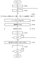
- FIG. 15 is a flowchart of distance measurement and image data generation in the sensing device 100B of FIG.
- the variable i is initialized (S100), and then the variable j is initialized (S102).
- the cell CELL i is repeatedly irradiated with the illumination light Sref ij of the pattern PTN ij L times, and the delay time ⁇ ij of the output Sp ij of the light receiving element PT i is acquired for each irradiation (S104).
- a histogram HIST ij is generated based on the measurement results of L delay times ⁇ ij (S106).
- the distance information Di of the cell CELL i is generated based on the histogram HIST ij (S108). Further, the detection intensity bij is generated based on the histogram HIST ij (S110).
- variable j is incremented (S112), and the illumination light pattern PTN ij is updated.
- the process returns to process S104.
- j> M (Y in S114) the image data Gi (x, y ) is generated by the correlation method (S116).
- variable i is incremented (S118), and the measurement proceeds to the next cell CELL i .
- i> N is not (N in S120), that is, when the processing of all N cells is not completed, the process returns to processing S102.
- i> N (Y in S120)
- the above is the operation of the sensing device 100B.
- this sensing device 100B it was decided to pattern the illumination light used in the ToF method and generate a histogram for distance measurement.
- distance information can be acquired using the histogram, and the output signal of the light receiving element with binary output can be converted into multi-valued detection intensity, and image data can be generated based on the correlation method. Become.
- a plurality of cells are sequentially time-divisioned, but they may be processed in parallel.
- a plurality of cells CELL 1 to CELL N are arranged in a matrix, but they may be arranged in a one-dimensional manner in the horizontal direction in one row and N columns.
- the lighting device 110 is composed of a combination of the light source 112 and the patterning device 114, but the present invention is not limited to this.
- the lighting device 110 is composed of an array of a plurality of semiconductor light sources (LED (light emitting diode) and LD (laser diode)) arranged in a matrix, and can control on / off (or brightness) of each semiconductor light source. It may be configured as.
- the lighting device 110 may irradiate a part of each cell (for example, only the center) in a spot shape.
- a method using correlation calculation has been described as a method of ghost imaging (or single pixel imaging), but the method of image reconstruction is not limited thereto.
- an analytical method using Fourier transform or Hadamard transform instead of correlation calculation, a method for solving an optimization problem such as sparse modeling, and an algorithm using AI / machine learning are used. The image may be reconstructed.
- FIG. 16 is a block diagram of the object identification system 10.
- This object identification system 10 is mounted on a vehicle such as an automobile or a motorcycle, and determines the type (category) of the object OBJ existing around the vehicle.
- the object identification system 10 includes any of the sensing devices 100, 100A, and 100B (simply referred to as 100) described in the first to third embodiments, and the arithmetic processing device 40. As described above, the sensing device 100 irradiates the object OBJ with the illumination light Sref and measures the reflected light S2 to generate the restored image G of the object OBJ.
- the arithmetic processing device 40 processes the output image G of the sensing device 100, and determines the position and type (category) of the object OBJ.
- the classifier 42 of the arithmetic processing device 40 receives the image G as an input and determines the position and type of the object OBJ included in the image G.
- the classifier 42 is implemented based on the model generated by machine learning.
- the algorithm of the classifier 42 is not particularly limited, but is YOLO (You Only Look Once), SSD (Single Shot MultiBox Detector), R-CNN (Region-based Convolutional Neural Network), SPPnet (Spatial Pyramid Pooling), Faster R-CNN. , DSSD (Deconvolution-SSD), Mask R-CNN, etc. can be adopted, or algorithms developed in the future can be adopted.
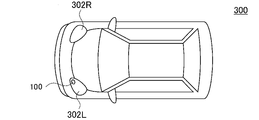
- FIG. 17 is a diagram showing an automobile equipped with a sensing device 100.
- the automobile 300 includes headlights 302L and 302R.
- the sensing device 100 is built in at least one of the headlights 302L and 302R.
- the headlight 302 is located at the tip of the vehicle body, and is the most advantageous as an installation location of the sensing device 100 in detecting surrounding objects.
- FIG. 18 is a block diagram showing a vehicle lamp 200 provided with an object detection system 210.
- the vehicle lamp 200 constitutes the lamp system 310 together with the vehicle side ECU 304.
- the vehicle lamp 200 includes a light source 202, a lighting circuit 204, and an optical system 206. Further, the vehicle lamp 200 is provided with an object detection system 210.
- the object detection system 210 corresponds to the above-mentioned object identification system 10, and includes a sensing device 100 and an arithmetic processing device 40.
- the information about the object OBJ detected by the arithmetic processing device 40 may be used for the light distribution control of the vehicle lamp 200.
- the lamp side ECU 208 generates an appropriate light distribution pattern based on the information regarding the type of the object OBJ generated by the arithmetic processing device 40 and its position.
- the lighting circuit 204 and the optical system 206 operate so as to obtain the light distribution pattern generated by the lamp side ECU 208.
- the information about the object OBJ detected by the arithmetic processing device 40 may be transmitted to the vehicle side ECU 304.
- the vehicle-side ECU may perform automatic driving based on this information.
- the application of the sensing device 100 is not limited to in-vehicle use, and can be applied to other applications.
- This disclosure relates to a sensing device.
- OBJ object 10 object identification system, 40 arithmetic processing device, 42 classifier, 100 sensing device, 110 lighting device, 112 light source, 114 patterning device, 116 pattern generator, 120 light receiving element array, 130 arithmetic processing device, 132 ToF processing Unit, 134 SPI processing unit, 200 vehicle lighting, 202 light source, 204 lighting circuit, 206 optical system, 300 automobile, 302 headlight, 310 lighting system, 304 vehicle side ECU
Landscapes
- Engineering & Computer Science (AREA)
- Physics & Mathematics (AREA)
- Radar, Positioning & Navigation (AREA)
- Remote Sensing (AREA)
- Computer Networks & Wireless Communication (AREA)
- Electromagnetism (AREA)
- General Physics & Mathematics (AREA)
- Optical Radar Systems And Details Thereof (AREA)
Abstract
Description
本開示のいくつかの例示的な実施形態の概要を説明する。この概要は、後述する詳細な説明の前置きとして、実施形態の基本的な理解を目的として、1つまたは複数の実施形態のいくつかの概念を簡略化して説明するものであり、発明あるいは開示の広さを限定するものではない。またこの概要は、考えられるすべての実施形態の包括的な概要ではなく、実施形態の欠くべからざる構成要素を限定するものではない。便宜上、「一実施形態」は、本明細書に開示するひとつの実施形態(実施例や変形例)または複数の実施形態(実施例や変形例)を指すものとして用いる場合がある。
以下、本発明を好適な実施形態をもとに図面を参照しながら説明する。各図面に示される同一または同等の構成要素、部材、処理には、同一の符号を付するものとし、適宜重複した説明は省略する。また、実施形態は、発明を限定するものではなく例示であって、実施形態に記述されるすべての特徴やその組み合わせは、必ずしも発明の本質的なものであるとは限らない。
τi=2×di/c
となる。つまり遅延時間τiは距離diに比例する。演算処理装置130は、発光タイミングから検出信号Spiの変化までの遅延時間τiを取得することで、距離diを示す距離情報Diを得ることができる。
図1では、複数のセルCELL1~CELLNがマトリクス状に配置されたが、1行N列の横方向の一次元の配置としてもよい。
画像データの生成と測距は、別々に行ってもよいが、画像データの生成と同時に、測距を行ってもよい。図5に示すように、受光素子PTiの出力Spijが変化するタイミングと、対応する照明光Srefijの発光タイミングの遅延時間τiは物体OBJiまでの距離diに比例する。そこで、画像データの生成のためのパターニングされた照明光を利用して、遅延時間を測定し、距離を取得してもよい。
実施形態では、照明装置110を、光源112とパターニングデバイス114の組み合わせで構成したがその限りでない。たとえば照明装置110は、マトリクス状に配置される複数の半導体光源(LED(発光ダイオード)やLD(レーザダイオード))のアレイで構成し、個々の半導体光源のオン、オフ(あるいは輝度)を制御可能に構成してもよい。
ToF法にもとづいて距離情報を生成する際に、照明装置110は、各セルの一部分(たとえば中央のみ)にスポット状に照明光を照射してもよい。
実施の形態において、ゴーストイメージング(あるいはシングルピクセルイメージング)の手法として、相関計算を用いた手法を説明したが、画像の再構築の手法はそれに限定されない。いくつかの実施の形態では、相関計算に変えて、フーリエ変換やアダマール逆変換を使用した解析的手法や、スパースモデリングなどの最適化問題を解く手法、およびAI・機械学習を利用したアルゴリズムによって、画像を再構築してもよい。
図7は、実施形態2に係るセンシング装置100Aを示す図である。センシング装置100Aは、視野FOVを複数N個のセルCELL1~CELLNに分割してセンシングを行う。

Tdi=2×di/c
となる。つまりラウンドトリップ時間Tdiは距離diに比例する。
図13は、実施形態3に係るセンシング装置100Bを示す図である。センシング装置100Bは、視野FOVを複数N個のセルCELL1~CELLNに分割してセンシングを行う。
i>Nでないとき(S120のN)、つまりN個すべてのセルの処理が完了していない場合、処理S102に戻る。i>Nであるとき(S120のY)、処理を終了する。
図7では、複数のセルCELL1~CELLNがマトリクス状に配置されたが、1行N列の横方向の一次元の配置としてもよい。
実施の形態では、照明装置110を、光源112とパターニングデバイス114の組み合わせで構成したがその限りでない。たとえば照明装置110は、マトリクス状に配置される複数の半導体光源(LED(発光ダイオード)やLD(レーザダイオード))のアレイで構成し、個々の半導体光源のオン、オフ(あるいは輝度)を制御可能に構成してもよい。
実施形態2において、ToF法にもとづいて距離情報を生成する際に、照明装置110は、各セルの一部分(たとえば中央のみ)にスポット状に照明光を照射してもよい。
実施の形態において、ゴーストイメージング(あるいはシングルピクセルイメージング)の手法として、相関計算を用いた手法を説明したが、画像の再構築の手法はそれに限定されない。いくつかの実施の形態では、相関計算に変えて、フーリエ変換やアダマール逆変換を使用した解析的手法や、スパースモデリングなどの最適化問題を解く手法、およびAI・機械学習を利用したアルゴリズムによって、画像を再構築してもよい。
続いてセンシング装置100の用途を説明する。図16は、物体識別システム10のブロック図である。この物体識別システム10は、自動車やバイクなどの車両に搭載され、車両の周囲に存在する物体OBJの種類(カテゴリ)を判定する。
Claims (14)
- 視野を分割してなる複数のセルそれぞれに、空間的にパターニングされた照明光を照射可能な照明装置と、
前記複数のセルに対応する複数の受光素子を含む受光素子アレイと、
ToF(飛行時間)法にもとづいて、前記複数のセルごとの距離情報を生成するとともに、相関法にもとづいて、前記複数のセルの画像データを生成する演算処理装置と、
を備えることを特徴とするセンシング装置。 - 前記照明装置は、各セルに、強度分布がランダムな複数個の照明光をシーケンシャルに照射し、
前記演算処理装置は、各受光素子の出力にもとづいて、対応するセルの前記距離情報をToF法により取得するとともに、対応するセルの前記画像データを相関法により生成することを特徴とする請求項1に記載のセンシング装置。 - 前記相関法にもとづいて前記画像データを生成する際に、前記照明装置は、各セルに、強度分布がランダムな複数個の照明光をシーケンシャルに照射することを特徴とする請求項1に記載のセンシング装置。
- 前記ToF法にもとづいて前記距離情報を生成する際に、前記照明装置は、各セルに均一な照明光を照射することを特徴とする請求項3に記載のセンシング装置。
- 前記ToF法にもとづいて前記距離情報を生成する際に、前記照明装置は、各セルの一部分に照明光を照射することを特徴とする請求項3に記載のセンシング装置。
- 視野を分割してなる複数N個(N≧2)のセルそれぞれに、空間的にパターニングされた照明光を照射可能な照明装置と、
それぞれが2値の検出信号を出力するK(K≧2)×N個の受光素子を含み、前記複数N個のセルそれぞれに対して、K個の受光素子が割り当てられている受光素子アレイと、
(i)ToF(飛行時間)法により、前記複数N個のセルそれぞれについて、各セルに対応するK個の受光素子の少なくともひとつの出力にもとづいて距離情報を生成するとともに、(ii)前記複数N個のセルそれぞれについて、各セルに対応するK個の受光素子の出力にもとづいて、多値の検出強度を生成し、相関法により、各セルの画像データを生成する演算処理装置と、
を備えることを特徴とするセンシング装置。 - 前記相関法による前記画像データの生成の際に、前記照明装置は、各セルに、強度分布がランダムな複数個の照明光をシーケンシャルに照射することを特徴とする請求項6に記載のセンシング装置。
- 前記ToF法による前記距離情報の生成の際に、前記照明装置は、各セルに均一な照明光を照射することを特徴とする請求項7に記載のセンシング装置。
- 前記ToF法による前記距離情報の生成の際に、前記照明装置は、各セルの一部分に照明光を照射することを特徴とする請求項7に記載のセンシング装置。
- 前記ToF法による前記距離情報の生成は、前記相関法による前記画像データの生成の際に前記照明装置が生成する前記複数個の照明光を利用して行うことを特徴とする請求項7に記載のセンシング装置。
- 視野を分割してなる複数N個(N≧2)のセルそれぞれに、空間的にパターニングされた照明光を照射可能な照明装置と、
前記複数N個のセルに対応し、それぞれが2値の検出信号を出力する複数N個の受光素子を含む受光素子アレイと、
(i)前記複数N個のセルそれぞれについて、前記N個の受光素子の対応するひとつが出力する前記検出信号にもとづいて、ToF(飛行時間)法により、距離を階級とするヒストグラムを生成し、前記ヒストグラムにもとづいて各セルの距離情報を生成するとともに、(ii)前記ヒストグラムにもとづいて検出強度を生成し、当該検出強度を利用した相関法により、各セルの画像データを生成する演算処理装置と、
を備えることを特徴とするセンシング装置。 - 前記演算処理装置は、前記ヒストグラムの最頻値における度数を、前記検出強度とすることを特徴とする請求項11に記載のセンシング装置。
- 請求項1から12のいずれかに記載のセンシング装置を備えることを特徴とする車両用灯具。
- 請求項1から12のいずれかに記載のセンシング装置を備えることを特徴とする車両。
Priority Applications (2)
| Application Number | Priority Date | Filing Date | Title |
|---|---|---|---|
| CN202180075232.1A CN116457700A (zh) | 2020-11-16 | 2021-11-15 | 感测装置、车辆用灯具、车辆 |
| JP2022562223A JPWO2022102775A1 (ja) | 2020-11-16 | 2021-11-15 |
Applications Claiming Priority (4)
| Application Number | Priority Date | Filing Date | Title |
|---|---|---|---|
| JP2020190201 | 2020-11-16 | ||
| JP2020-190200 | 2020-11-16 | ||
| JP2020-190201 | 2020-11-16 | ||
| JP2020190200 | 2020-11-16 |
Publications (1)
| Publication Number | Publication Date |
|---|---|
| WO2022102775A1 true WO2022102775A1 (ja) | 2022-05-19 |
Family
ID=81601358
Family Applications (1)
| Application Number | Title | Priority Date | Filing Date |
|---|---|---|---|
| PCT/JP2021/041926 Ceased WO2022102775A1 (ja) | 2020-11-16 | 2021-11-15 | センシング装置、車両用灯具、車両 |
Country Status (2)
| Country | Link |
|---|---|
| JP (1) | JPWO2022102775A1 (ja) |
| WO (1) | WO2022102775A1 (ja) |
Citations (5)
| Publication number | Priority date | Publication date | Assignee | Title |
|---|---|---|---|---|
| US8242428B2 (en) * | 2007-12-06 | 2012-08-14 | The United States Of America As Represented By The Secretary Of The Army | Method and system for lidar using spatial information from a light source in combination with nonspatial information influenced by the subject to derive an image |
| WO2017187484A1 (ja) * | 2016-04-25 | 2017-11-02 | 株式会社日立製作所 | 物体撮像装置 |
| JP2019060652A (ja) * | 2017-09-25 | 2019-04-18 | シャープ株式会社 | 測距センサ |
| WO2020149140A1 (ja) * | 2019-01-17 | 2020-07-23 | 株式会社小糸製作所 | 車載用イメージング装置、車両用灯具、自動車 |
| JP2020136837A (ja) * | 2019-02-15 | 2020-08-31 | 日本放送協会 | 3次元画像用の撮像装置および3次元画像用の撮像表示装置 |
-
2021
- 2021-11-15 JP JP2022562223A patent/JPWO2022102775A1/ja active Pending
- 2021-11-15 WO PCT/JP2021/041926 patent/WO2022102775A1/ja not_active Ceased
Patent Citations (5)
| Publication number | Priority date | Publication date | Assignee | Title |
|---|---|---|---|---|
| US8242428B2 (en) * | 2007-12-06 | 2012-08-14 | The United States Of America As Represented By The Secretary Of The Army | Method and system for lidar using spatial information from a light source in combination with nonspatial information influenced by the subject to derive an image |
| WO2017187484A1 (ja) * | 2016-04-25 | 2017-11-02 | 株式会社日立製作所 | 物体撮像装置 |
| JP2019060652A (ja) * | 2017-09-25 | 2019-04-18 | シャープ株式会社 | 測距センサ |
| WO2020149140A1 (ja) * | 2019-01-17 | 2020-07-23 | 株式会社小糸製作所 | 車載用イメージング装置、車両用灯具、自動車 |
| JP2020136837A (ja) * | 2019-02-15 | 2020-08-31 | 日本放送協会 | 3次元画像用の撮像装置および3次元画像用の撮像表示装置 |
Non-Patent Citations (1)
| Title |
|---|
| CAO JIE; ZHANG FANGHUA; ZHANG KAIYU; WANG FEI; HAO QUN; FANG YAMI; LUO QIANG: "Three-dimensional ghost imaging based on differential optical path", SPIE PROCEEDINGS, SPIE, US, vol. 10997, 14 May 2019 (2019-05-14), US , pages 109970T - 109970T-7, XP060121892, ISBN: 978-1-5106-3673-6, DOI: 10.1117/12.2523306 * |
Also Published As
| Publication number | Publication date |
|---|---|
| JPWO2022102775A1 (ja) | 2022-05-19 |
Similar Documents
| Publication | Publication Date | Title |
|---|---|---|
| JP5938125B2 (ja) | Ir画像内の生物の数を決定するための方法 | |
| US11009592B2 (en) | LiDAR system and method | |
| CN113227838B (zh) | 车辆用灯具及车辆 | |
| US12135394B2 (en) | Gating camera | |
| EP3998767B1 (en) | Imaging device, lighting device for same, vehicle, and lamp fitting for vehicle | |
| JP7463297B2 (ja) | 車載用イメージング装置、車両用灯具、自動車 | |
| US20230179841A1 (en) | Gating camera | |
| WO2021193646A1 (ja) | イメージング装置および車両用灯具、車両 | |
| CN119716845B (zh) | 远距离快照式光谱成像雷达系统及其应用 | |
| WO2022102775A1 (ja) | センシング装置、車両用灯具、車両 | |
| JP7395511B2 (ja) | イメージング装置、その演算処理装置、車両用灯具、車両、センシング方法 | |
| CN116457700A (zh) | 感测装置、车辆用灯具、车辆 | |
| JP7608353B2 (ja) | イメージング装置、車両用灯具、車両、イメージング方法 | |
| US20240067094A1 (en) | Gating camera, vehicle sensing system, and vehicle lamp | |
| JP7804684B2 (ja) | ゲーティングカメラ、車両用センシングシステム、車両用灯具 | |
| US12517251B2 (en) | Imaging apparatus | |
| US20250095106A1 (en) | Gating camera, sensing system for vehicle, vehicle lamp | |
| WO2023085329A1 (ja) | イメージングシステム、センサユニット、車両用灯具、車両 | |
| JP2025166703A (ja) | 光学装置および移動装置 |
Legal Events
| Date | Code | Title | Description |
|---|---|---|---|
| 121 | Ep: the epo has been informed by wipo that ep was designated in this application |
Ref document number: 21892020 Country of ref document: EP Kind code of ref document: A1 |
|
| WWE | Wipo information: entry into national phase |
Ref document number: 202180075232.1 Country of ref document: CN |
|
| ENP | Entry into the national phase |
Ref document number: 2022562223 Country of ref document: JP Kind code of ref document: A |
|
| NENP | Non-entry into the national phase |
Ref country code: DE |
|
| 122 | Ep: pct application non-entry in european phase |
Ref document number: 21892020 Country of ref document: EP Kind code of ref document: A1 |