WO2022102024A1 - 鉄亜鉛電池 - Google Patents
鉄亜鉛電池 Download PDFInfo
- Publication number
- WO2022102024A1 WO2022102024A1 PCT/JP2020/042120 JP2020042120W WO2022102024A1 WO 2022102024 A1 WO2022102024 A1 WO 2022102024A1 JP 2020042120 W JP2020042120 W JP 2020042120W WO 2022102024 A1 WO2022102024 A1 WO 2022102024A1
- Authority
- WO
- WIPO (PCT)
- Prior art keywords
- iron
- zinc
- positive electrode
- negative electrode
- battery
- Prior art date
- Legal status (The legal status is an assumption and is not a legal conclusion. Google has not performed a legal analysis and makes no representation as to the accuracy of the status listed.)
- Ceased
Links
Images



Classifications
-
- H—ELECTRICITY
- H01—ELECTRIC ELEMENTS
- H01M—PROCESSES OR MEANS, e.g. BATTERIES, FOR THE DIRECT CONVERSION OF CHEMICAL ENERGY INTO ELECTRICAL ENERGY
- H01M10/00—Secondary cells; Manufacture thereof
- H01M10/36—Accumulators not provided for in groups H01M10/05-H01M10/34
- H01M10/38—Construction or manufacture
-
- H—ELECTRICITY
- H01—ELECTRIC ELEMENTS
- H01M—PROCESSES OR MEANS, e.g. BATTERIES, FOR THE DIRECT CONVERSION OF CHEMICAL ENERGY INTO ELECTRICAL ENERGY
- H01M10/00—Secondary cells; Manufacture thereof
- H01M10/36—Accumulators not provided for in groups H01M10/05-H01M10/34
-
- H—ELECTRICITY
- H01—ELECTRIC ELEMENTS
- H01M—PROCESSES OR MEANS, e.g. BATTERIES, FOR THE DIRECT CONVERSION OF CHEMICAL ENERGY INTO ELECTRICAL ENERGY
- H01M4/00—Electrodes
- H01M4/02—Electrodes composed of, or comprising, active material
- H01M4/36—Selection of substances as active materials, active masses, active liquids
- H01M4/38—Selection of substances as active materials, active masses, active liquids of elements or alloys
- H01M4/42—Alloys based on zinc
-
- H—ELECTRICITY
- H01—ELECTRIC ELEMENTS
- H01M—PROCESSES OR MEANS, e.g. BATTERIES, FOR THE DIRECT CONVERSION OF CHEMICAL ENERGY INTO ELECTRICAL ENERGY
- H01M4/00—Electrodes
- H01M4/02—Electrodes composed of, or comprising, active material
- H01M4/36—Selection of substances as active materials, active masses, active liquids
- H01M4/48—Selection of substances as active materials, active masses, active liquids of inorganic oxides or hydroxides
-
- H—ELECTRICITY
- H01—ELECTRIC ELEMENTS
- H01M—PROCESSES OR MEANS, e.g. BATTERIES, FOR THE DIRECT CONVERSION OF CHEMICAL ENERGY INTO ELECTRICAL ENERGY
- H01M4/00—Electrodes
- H01M4/02—Electrodes composed of, or comprising, active material
- H01M4/36—Selection of substances as active materials, active masses, active liquids
- H01M4/48—Selection of substances as active materials, active masses, active liquids of inorganic oxides or hydroxides
- H01M4/52—Selection of substances as active materials, active masses, active liquids of inorganic oxides or hydroxides of nickel, cobalt or iron
- H01M4/521—Selection of substances as active materials, active masses, active liquids of inorganic oxides or hydroxides of nickel, cobalt or iron of iron for aqueous cells
-
- H—ELECTRICITY
- H01—ELECTRIC ELEMENTS
- H01M—PROCESSES OR MEANS, e.g. BATTERIES, FOR THE DIRECT CONVERSION OF CHEMICAL ENERGY INTO ELECTRICAL ENERGY
- H01M4/00—Electrodes
- H01M4/02—Electrodes composed of, or comprising, active material
- H01M4/64—Carriers or collectors
- H01M4/66—Selection of materials
- H01M4/661—Metal or alloys, e.g. alloy coatings
-
- H—ELECTRICITY
- H01—ELECTRIC ELEMENTS
- H01M—PROCESSES OR MEANS, e.g. BATTERIES, FOR THE DIRECT CONVERSION OF CHEMICAL ENERGY INTO ELECTRICAL ENERGY
- H01M4/00—Electrodes
- H01M4/02—Electrodes composed of, or comprising, active material
- H01M2004/026—Electrodes composed of, or comprising, active material characterised by the polarity
- H01M2004/029—Bipolar electrodes
-
- H—ELECTRICITY
- H01—ELECTRIC ELEMENTS
- H01M—PROCESSES OR MEANS, e.g. BATTERIES, FOR THE DIRECT CONVERSION OF CHEMICAL ENERGY INTO ELECTRICAL ENERGY
- H01M2300/00—Electrolytes
- H01M2300/0002—Aqueous electrolytes
-
- H—ELECTRICITY
- H01—ELECTRIC ELEMENTS
- H01M—PROCESSES OR MEANS, e.g. BATTERIES, FOR THE DIRECT CONVERSION OF CHEMICAL ENERGY INTO ELECTRICAL ENERGY
- H01M2300/00—Electrolytes
- H01M2300/0002—Aqueous electrolytes
- H01M2300/0014—Alkaline electrolytes
-
- Y—GENERAL TAGGING OF NEW TECHNOLOGICAL DEVELOPMENTS; GENERAL TAGGING OF CROSS-SECTIONAL TECHNOLOGIES SPANNING OVER SEVERAL SECTIONS OF THE IPC; TECHNICAL SUBJECTS COVERED BY FORMER USPC CROSS-REFERENCE ART COLLECTIONS [XRACs] AND DIGESTS
- Y02—TECHNOLOGIES OR APPLICATIONS FOR MITIGATION OR ADAPTATION AGAINST CLIMATE CHANGE
- Y02E—REDUCTION OF GREENHOUSE GAS [GHG] EMISSIONS, RELATED TO ENERGY GENERATION, TRANSMISSION OR DISTRIBUTION
- Y02E60/00—Enabling technologies; Technologies with a potential or indirect contribution to GHG emissions mitigation
- Y02E60/10—Energy storage using batteries
-
- Y—GENERAL TAGGING OF NEW TECHNOLOGICAL DEVELOPMENTS; GENERAL TAGGING OF CROSS-SECTIONAL TECHNOLOGIES SPANNING OVER SEVERAL SECTIONS OF THE IPC; TECHNICAL SUBJECTS COVERED BY FORMER USPC CROSS-REFERENCE ART COLLECTIONS [XRACs] AND DIGESTS
- Y02—TECHNOLOGIES OR APPLICATIONS FOR MITIGATION OR ADAPTATION AGAINST CLIMATE CHANGE
- Y02P—CLIMATE CHANGE MITIGATION TECHNOLOGIES IN THE PRODUCTION OR PROCESSING OF GOODS
- Y02P70/00—Climate change mitigation technologies in the production process for final industrial or consumer products
- Y02P70/50—Manufacturing or production processes characterised by the final manufactured product
Definitions
- the present invention relates to an iron-zinc battery.
- Batteries currently in general use are often composed of rare metals such as lithium, nickel, manganese, and cobalt, and there is a problem of resource depletion.
- Patent Document 1 An air battery with a low environmental load is being studied.
- Patent Document 1 The battery principle of Patent Document 1 is an air battery, and since oxygen in the air is used as a positive electrode active material, an air intake port is indispensable for the battery. Therefore, the air battery has a drawback that the electrolytic solution volatilizes from the air intake port and is not suitable for long-term storage. Therefore, there is a demand for a new low environmental load battery capable of battery reaction in a closed system.
- the present invention has been made in view of the above circumstances, and an object of the present invention is to provide an iron-zinc battery capable of long-term storage with a low environmental load.
- the iron-zinc battery according to one aspect of the present invention comprises a positive electrode containing iron oxyhydroxide, a negative electrode containing zinc, and an aqueous electrolytic solution arranged between the positive electrode and the negative electrode, and the aqueous electrolytic solution.
- aqueous electrolytic solution arranged between the positive electrode and the negative electrode, and the aqueous electrolytic solution.
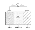
- FIG. 1 is a basic schematic diagram of the iron-zinc battery of the present embodiment.
- FIG. 2 is a schematic cross-sectional view showing the structure of a coin-type iron-zinc battery.
- FIG. 3A is a configuration diagram showing a configuration example of a bipolar type stacked iron-zinc battery.
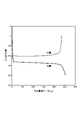
- FIG. 3B is a plan view showing a configuration example of a bipolar type stacked iron-zinc battery. It is a graph which shows the first charge / discharge curve of the iron-zinc battery of Example 1.
- FIG. It is a figure which shows the cycle dependence of the discharge capacity of the iron-zinc battery of Examples 1 to 4.
- FIG. 1 is a block diagram showing a configuration of an iron-zinc battery according to an embodiment of the present invention.
- This iron-zinc battery includes a positive electrode 101 containing iron oxyhydroxide, a negative electrode 103 containing zinc, and an aqueous electrolytic solution 102 arranged between the positive electrode 101 and the negative electrode 103.
- the positive electrode 101 is configured by using iron oxyhydroxide as an active material.
- the negative electrode 103 is configured using zinc as an active material.
- the aqueous electrolyte 102 is arranged so as to be in contact with the positive electrode 101 and the negative electrode 103.
- the iron-zinc battery of the present embodiment is characterized in that the positive electrode 101 contains the active material of iron oxyhydroxide and the negative electrode 103 contains the active material of zinc.
- the discharge reaction at the positive electrode 101 can be expressed as follows.
- the discharge reaction at the negative electrode 103 can be expressed as follows.
- the iron-zinc battery of the present embodiment is composed of an inexpensive material by using iron oxyhydroxide as the positive electrode active material, zinc as the negative electrode active material, and an aqueous electrolytic solution as the electrolytic solution, and has a low environmental load. It can be expected as a good battery.
- the positive electrode 101 can include a positive electrode active material and a conductive auxiliary agent as components. Further, it is preferable that the positive electrode 101 contains a binder for integrating the materials.
- the negative electrode 103 can include a negative electrode active material and a conductive auxiliary agent as components. Further, it is preferable that the negative electrode 103 contains a binder for integrating the materials.
- the positive electrode contains at least a positive electrode active material, and may contain additives such as a conductive auxiliary agent and a binder, if necessary.
- the positive electrode may be applied to a sheet-like current collector containing at least one selected from the group consisting of copper, iron and carbon.
- the positive electrode active material of the present embodiment contains at least iron oxyhydroxide (FeOOH).
- the iron oxyhydroxide has four phases of ⁇ phase, ⁇ phase, ⁇ phase, and ⁇ phase having different crystal forms, but the ⁇ phase is preferable from the viewpoint of cost and productivity.
- the particle size of the positive electrode active material is preferably 0.3 ⁇ m to 10 ⁇ m, and more preferably 0.5 ⁇ m to 5 ⁇ m.
- iron oxyhydroxide For iron oxyhydroxide, a method of oxidizing iron hydroxide (Fe (OH) 2 ) in a pH-controlled aqueous solution, a method of heating an iron chloride (FeCl 3 ) aqueous solution, and iron hydroxide (Fe (OH) 2 ) dispersion. It can be produced by an existing method such as a method of adding hydrogen peroxide (H 2 O 2 ) to the liquid. It is also possible to use commercially available iron oxyhydroxide.
- the positive electrode may contain a conductive auxiliary agent.
- a conductive auxiliary agent for example, carbon or the like can be used as the conductive auxiliary agent.
- Specific examples thereof include carbon blacks such as Ketjen black and acetylene black, activated carbons, graphites, carbon fibers and the like.
- carbon having small particles is suitable. Specifically, it is desirable that the particle size is 1 ⁇ m or less. These carbons can be obtained, for example, as commercial products or by known synthesis.
- Carbon may be directly coated on the positive electrode active material.
- the coating method can be a physical method such as thin film deposition, sputtering or a planetary ball mill, a chemical method such as heat treatment after coating an organic substance, or a known method.
- the positive electrode may contain a binder.
- the binder is not particularly limited, and examples thereof include polytetrafluoroethylene (PTFE), polyvinylidene fluoride (PVDF), styrene butadiene rubber, ethylene propylene diene rubber, and natural rubber. From the viewpoint of environmental load and waste treatment, styrene-butadiene rubber, ethylene propylene diene rubber, and natural rubber that do not contain fluorine are more preferable.
- binders can be used as a powder or as a dispersion.
- the content of the positive electrode active material, the conductive auxiliary agent and the binder in the positive electrode of the present embodiment is greater than 0% by weight and 99% or less, preferably 70 to 95% by weight, based on the weight of the entire positive electrode. %,
- the conductive auxiliary agent is 0 to 90% by weight, preferably 1 to 30% by weight, and the binder is 0 to 50% by weight, preferably 1 to 30% by weight.
- the positive electrode can be prepared as follows.
- a positive electrode is formed by mixing a dispersion liquid such as iron oxyhydroxide powder, carbon powder, and, if necessary, styrene-butadiene rubber, which are positive electrode active materials, and applying this mixture to a current collector and drying it. be able to.
- the current collector is not particularly limited, and for example, a sheet-shaped or mesh-shaped current collector using at least one (one element) selected from the group consisting of copper, iron, titanium, nickel, and carbon is used. can do.
- the current collector is preferably in the form of a sheet. Further, from the viewpoint of environmental load and disposal, a sheet-shaped current collector containing at least one selected from the group consisting of copper, iron and carbon is more preferable. As described above, the positive electrode is preferably applied to a sheet-shaped current collector containing at least one selected from the group consisting of copper, iron and carbon.
- a positive electrode containing iron oxyhydroxide which is a positive electrode active material
- a positive electrode having high activity against a charge reaction and a discharge reaction can be obtained.
- the positive electrode of the iron-zinc battery having the above-mentioned structure it is possible to sufficiently draw out the potential of iron oxyhydroxide, which is the positive electrode active material.
- Negative electrode contains at least a negative electrode active material, and may contain additives such as a conductive auxiliary agent and a binder, if necessary.
- the negative electrode may be applied to a sheet-like current collector containing at least one selected from the group consisting of copper, iron and carbon.
- Negative electrode active material contains at least zinc (Zn).
- the negative electrode active material can be produced by molding a zinc foil into a predetermined shape, but it is preferably used as a powder.
- the particle size of the negative electrode active material is preferably 0.3 ⁇ m to 10 ⁇ m, and more preferably 0.5 ⁇ m to 5 ⁇ m. This is because the smaller the particle size, the more sites that react and the output performance is improved, while if the particle size is too small, the oxidation of zinc and the progress of corrosion by the electrolytic solution are accelerated.
- the negative electrode may contain a conductive auxiliary agent.
- a conductive auxiliary agent for example, carbon or the like can be used as the conductive auxiliary agent.
- Specific examples thereof include carbon blacks such as Ketjen black and acetylene black, activated carbons, graphites, carbon fibers and the like.
- carbon having small particles is suitable. Specifically, it is desirable that the particle size is 1 ⁇ m or less. These carbons can be obtained, for example, as commercial products or by known synthesis.
- Carbon may be directly coated on the negative electrode active material.
- the coating method can be a physical method such as thin film deposition, sputtering or a planetary ball mill, a chemical method such as heat treatment after coating an organic substance, or a known method.
- the negative electrode may contain a binder.
- the binder is not particularly limited, and examples thereof include polytetrafluoroethylene (PTFE), polyvinylidene fluoride (PVDF), styrene butadiene rubber, ethylene propylene diene rubber, and natural rubber. From the viewpoint of environmental load and waste treatment, styrene-butadiene rubber, ethylene propylene diene rubber, and natural rubber that do not contain fluorine are more preferable. These binders can be used as powders or as dispersions.
- the content of the negative electrode active material, the conductive auxiliary agent and the binder of the present embodiment is 99% or less, preferably 70 to 95% by weight, with the negative electrode active material being larger than 0% by weight and 99% or less based on the weight of the entire negative electrode.
- the conductive auxiliary agent is 0 to 90% by weight, preferably 1 to 30% by weight
- the binder is 0 to 50% by weight, preferably 1 to 30% by weight.
- the negative electrode can be prepared as follows.
- a negative electrode can be formed by mixing zinc powder, carbon powder, which is a negative electrode active material, and, if necessary, a dispersion liquid such as styrene-butadiene rubber, applying this mixture to a current collector, and drying the mixture. ..
- the current collector is not particularly limited, and for example, a sheet-shaped or mesh-shaped current collector using at least one (one element) selected from the group consisting of copper, iron, titanium, nickel, and carbon is used. can do.
- the current collector is preferably in the form of a sheet. Further, from the viewpoint of environmental load and disposal, a sheet-shaped current collector containing at least one selected from the group consisting of copper, iron and carbon is more preferable. As described above, the negative electrode is preferably applied to a sheet-shaped current collector containing at least one selected from the group consisting of copper, iron and carbon.
- a negative electrode containing zinc which is a negative electrode active material
- a negative electrode having high activity against a charge reaction and a discharge reaction can be obtained.
- the negative electrode of the iron-zinc battery having the above-mentioned structure it is possible to sufficiently draw out the potential of zinc, which is the negative electrode active material.
- the iron-zinc battery of the present embodiment contains an aqueous electrolytic solution capable of transferring hydroxide ions (OH ⁇ ) at the positive electrode and the negative electrode.
- the aqueous electrolyte solution of this embodiment is an aqueous solution containing zinc chloride (ZnCl 2 ) as an electrolyte.
- the aqueous electrolyte solution may contain other electrolytes in addition to zinc chloride (ZnCl 2 ).
- Other electrolytes include, for example, acetates, carbonates, phosphates, pyrophosphates, metaphosphates, citrates, borates, ammonium salts, formates, hydrogen carbonates, hydroxides, and. At least one selected from the group consisting of chlorides may be used. Therefore, the aqueous electrolyte may contain zinc chloride (ZnCl 2 ) and at least one selected from the above group.
- the aqueous electrolytic solution may be in the form of a liquid, a cream, a gel, or a solid. However, when the electrolytic solution is in the form of a gel or a solid, it is called a solid electrolyte.
- a strong alkaline aqueous solution such as potassium hydroxide (KOH) is used as the electrolytic solution, but in this embodiment, an aqueous electrolytic solution containing zinc chloride (ZnCl 2 ) is used. In order to improve the performance, it is preferable to increase the specific gravity of zinc chloride (ZnCl 2 ) in the aqueous electrolyte solution.
- KOH potassium hydroxide
- the aqueous electrolytic solution contains zinc chloride (ZnCl 2 ), and the weight of zinc chloride (ZnCl 2 ) is equal to or greater than the weight of water ( H2O ) contained in the aqueous electrolytic solution (ZnCl). 2 )
- An aqueous solution is preferable.
- a zinc chloride (ZnCl 2 ) concentrated electrolytic solution in which water ( H2O ) is 3 mol or less is more preferable with respect to 1 mol of zinc chloride (ZnCl 2 ).
- zinc in contact with water reacts with water to form a film of zinc oxide (ZnO) or zinc hydroxide (Zn (OH) 2 ), which causes an increase in battery overvoltage.
- ZnO zinc oxide
- Zn (OH) 2 zinc hydroxide
- ZnCl 2 zinc chloride
- all the water molecules in the electrolytic solution are zinc ions (Zn). Since 2+ ) is taken into consideration, the reaction between water molecules and zinc is suppressed, a film is less likely to be formed, and the operating voltage can be improved.
- the tetrahydroxide zincate ion (Zn (OH) 42-2- ) dissolved during the discharge is deposited as zinc (Zn) on the negative electrode.
- dendritic zinc (dendrite) grows and the negative electrode deteriorates rapidly. If it continues to grow, there is a problem that the separator is damaged and the battery is short-circuited.
- the problem caused by this dendrite is considered to be due to the coating of zinc oxide (ZnO) or zinc hydroxide (Zn (OH) 2 ) generated by reacting with water, and the concentration gradient of zinc ions in the electrolytic solution. .. Therefore, by using a zinc chloride (ZnCl 2 ) concentrated electrolytic solution, it is possible to suppress the concentration gradient of the coating film and zinc ions, and it is possible to suppress the formation of dendrites.
- the iron-zinc battery of the present embodiment may include structural members such as a separator and a battery case, and other elements required for the iron-zinc battery.
- structural members such as a separator and a battery case
- other elements required for the iron-zinc battery As these, conventionally known ones can be used, but from the viewpoint of environmental load and disposal, it is preferable that they do not contain harmful substances, rare metals, rare earths and the like. Furthermore, it is more preferred that these other elements are of biological origin and biodegradable material.
- the iron-zinc battery of the present embodiment contains at least a positive electrode, a negative electrode and an aqueous electrolytic solution as described above, and as illustrated in FIG. 1, between the positive electrode and the negative electrode.
- the aqueous electrolytic solution is arranged so as to be in contact with the positive electrode and the negative electrode.
- An iron-zinc battery having such a configuration can be prepared in the same manner as a conventional secondary battery.
- an iron-zinc battery has a positive electrode active material containing iron oxyhydroxide, a positive electrode containing a conductive auxiliary agent and a binder as described above, and a negative electrode containing a negative electrode active material containing zinc, a conductive auxiliary agent and a binder.
- the aqueous electrolytic solution arranged so as to be in contact with the positive electrode and the negative electrode, each element may be assembled according to the prior art.
- FIG. 2 is a schematic cross-sectional view showing the structure of a coin-type iron-zinc battery. Specifically, first, a separator (not shown) is placed in the positive electrode case 201 in which the positive electrode 101 is installed, and the electrolytic solution 102 is injected into the placed separator. Next, the negative electrode 103 is placed on the electrolytic solution 102, and the negative electrode case 202 is put on the positive electrode case 201. Next, by caulking the peripheral edges of the positive electrode case 201 and the negative electrode case 202 with a coin cell caulking machine, it is possible to manufacture a coin-type iron-zinc battery containing the propylene gasket 203.
- the illustrated coin-type iron-zinc battery uses iron oxyhydroxide powder as the positive electrode active material. Therefore, unlike an air battery that uses oxygen in the air as the positive electrode active material, the positive electrode case 201 of the present embodiment does not need to be provided with an air intake port. That is, in the present embodiment, a sealed battery can be manufactured. Therefore, the iron-zinc battery of the present embodiment can be stored for a long period of time without volatilizing the electrolytic solution from the air intake port.
- FIG. 3A is a configuration diagram showing a configuration example of a bipolar type stacked iron-zinc battery.
- FIG. 3B is a plan view showing a configuration example of a bipolar type stacked iron-zinc battery.
- the iron-zinc battery of this embodiment has a low theoretical battery voltage in a single cell, so the output performance cannot be expected. Therefore, it is preferable to increase the output by using an iron-zinc battery having a stack structure.
- the positive electrode 101 and the negative electrode 103 are applied to both sides of a current collector 322 such as a copper foil, dried and pressed, whereby the positive electrode 101 and the negative electrode are applied to one current collector 322, respectively.
- a current collector 322 such as a copper foil
- Each 103 is formed.
- each of the current collectors 303A and 303B for the outermost layer may be formed with an electrode on only one side, and it is preferable that the current collectors 303A and 303B have tabs 313A and 313B for extracting electricity.
- a positive electrode 101 is formed on only one side thereof, and a tab 313A is formed.
- a negative electrode 103 is formed on only one side of the current collector 303B in the outermost layer, and a tab 313B is formed.
- the tabs 313A and 313B may be processed into a shape having protrusions on the current collectors 303A and 303B, or another metal tab may be joined to the current collectors 303A and 303B by ultrasonic welding, spot welding or the like.
- the current collector 322 forming the positive electrode 101 and the negative electrode 103 is overlapped so that the positive electrode 101 and the negative electrode 103 face each other, and the separator 301 is inserted so as to be in contact with the positive electrode 101 and the negative electrode 103.
- the positive electrode 101 and the negative electrode 103 are overlapped so as to face each other, and the separator 301 is inserted so as to be in contact with the positive electrode 101 and the negative electrode 103. ..
- the peripheral edges of the copper foils of the current collectors are heat-pressed using the heat-sealing sheet 302 to seal them.
- one side (part) of the peripheral portion needs to be opened without hot pressing in order to inject the aqueous electrolytic solution described later.
- the created stack is sandwiched between aluminum laminated films 304 and the like, and after injecting an aqueous electrolyte into each cell (each room), the unsealed side of the stack and the peripheral edge of the aluminum laminated film are vacuum-sealed to perform bipolar. It is possible to manufacture a mold-type stack structure iron-zinc battery.
- Such an iron-zinc battery is a sealed battery that does not require an air intake port, unlike an air battery that uses oxygen in the air as the positive electrode active material. Therefore, the iron-zinc battery of the present embodiment can be stored for a long period of time without volatilizing the electrolytic solution from the air intake port.
- Example 1 the coin-shaped iron-zinc battery (FIG. 2) described above was produced by the following procedure.
- a sheet-shaped electrode (thickness: 0.5 mm) was produced by sufficiently pulverizing and mixing using a derailleur machine and rolling to form a sheet. This sheet-shaped electrode was cut out into a circle having a diameter of 16 mm and pressed onto a copper mesh to obtain a positive electrode.
- a zinc plate (thickness 150 ⁇ m, Niraco Co., Ltd.) was cut out into a circle having a diameter of 16 mm to obtain a negative electrode.
- a coin-type iron-zinc battery shown in FIG. 2 was manufactured using a coin battery case (Hosensha). A cellulosic separator (Nippon Advanced Paper Industry Co., Ltd.) cut out to a diameter of 18 mm was placed on the positive electrode case 201 on which the positive electrode 101 adjusted by the above method was installed, and 7.6 mol / L zinc chloride (ZnCl) was placed on the placed separator. 2 ) Inject the aqueous solution as the aqueous electrolyte 102.
- a coin battery case Hosensha
- a cellulosic separator Nippon Advanced Paper Industry Co., Ltd.
- ZnCl 7.6 mol / L zinc chloride
- a coin containing a propylene gasket 203 by installing the negative electrode 103 on the aqueous electrolyte 102, covering the negative electrode case 202 with the positive electrode case 201, and caulking the peripheral edges of the positive electrode case 201 and the negative electrode case 202 with a coin cell caulking machine. Obtained a type iron-zinc battery.
- the battery performance of the iron-zinc battery adjusted by the above procedure was measured.
- a charge / discharge measurement system manufactured by BioLogic
- the discharge voltage was measured until the voltage was increased.
- the battery charge test was performed at the same current density as when discharged until the battery voltage increased to 1.0 V.
- the battery discharge test was performed in a normal living environment.
- the charge / discharge capacity was expressed as a value (mAh / g) per unit weight of the positive electrode active material (iron oxyhydroxide).
- FIG. 4 shows the initial discharge curve and charge curve. From FIG. 4, it can be seen that when iron oxyhydroxide is used as the positive electrode active material, the average discharge voltage is 0.45 V and the discharge capacity is 254 mAh / g. Here, the average discharge voltage is defined as the discharge voltage when the discharge capacity is 1/2 of the total discharge capacity (here, 127 mAh / g).
- the initial charge capacity is 235 mAh / g, which is almost the same as the discharge capacity, and it can be seen that the reversibility is excellent.
- FIG. 5 shows the cycle dependence of the discharge capacity.
- Example 1 when the charge / discharge cycle was repeated 50 times, the initial discharge capacity decreased by 23%, but the behavior was more stable than that of Comparative Example 1 described later.
- the average charging voltage for the first time is 0.59V.
- the average charge voltage is defined as the charge voltage when the charge capacity is 1/2 of the total charge capacity. Further, from FIG. 4, the voltage at the time of charging has a flat portion at about 0.6 V.
- Example 1 The transition of charge / discharge voltage is shown in Table 1 below.
- Example 1 Although a slight increase in overvoltage was observed during charging and discharging, it was found that the voltage was almost stable. As described above, it was found that the iron-zinc battery has excellent cycle performance.
- Comparative Example 1 In Comparative Example 1, the coin-shaped iron-zinc battery described above was produced by the following procedure. A zinc plate was used as the negative electrode active material, and a 6 mol / L potassium hydroxide aqueous solution (KOH) was used as the strong alkaline electrolytic solution (pH of about 14) as the aqueous electrolytic solution.
- KOH potassium hydroxide aqueous solution
- Example 2 the coin-shaped iron-zinc battery described above was produced by the following procedure.
- a zinc plate was used as the negative electrode active material, and a zinc chloride (ZnCl 2 ) concentrated electrolytic solution in which water ( H2O ) was 3 mol with respect to 1 mol of zinc chloride (ZnCl 2 ) was used as the aqueous electrolytic solution. ..
- FIGS. 5 and 1 The cycle dependence of the discharge capacity and charge / discharge voltage of the iron-zinc battery of Example 2 is shown in FIGS. 5 and 1. As shown in FIG. 5, the discharge capacity of Example 2 was 290 mAh / g at the first time, which was larger than that of Example 1. It was also found that stable behavior was exhibited even after repeating the cycle.
- Example 1 the overvoltage was reduced as compared with Example 1 in the charge / discharge voltage, and the energy efficiency of charge / discharge could be improved. It was also confirmed that the charge / discharge voltage did not increase significantly even after repeated cycles, and that it operated stably.
- Example 3 the coin-shaped iron-zinc battery described above was produced by the following procedure.
- the positive electrode and the negative electrode are prepared by applying them to a copper sheet-shaped current collector, and the aqueous electrolytic solution contains zinc chloride (ZnCl) in which 1 mol of zinc chloride (ZnCl 2 ) and 3 mol of water (H 2 O). 2 ) A concentrated electrolytic solution was used.
- the manufacturing and evaluation method of the battery was carried out in the same manner as in Example 1.
- Zinc iron powder particles size 7 ⁇ m, high-purity chemical laboratory
- Ketjen black powder EC600JD, Lion Specialty Chemicals
- styrene-butadiene rubber AA Portable Power
- Zinc iron powder particle size 7 ⁇ m, high-purity chemical laboratory
- Ketjen black powder EC600JD, Lion Specialty Chemicals
- styrene-butadiene rubber AA Portable Power
- FIGS. 5 and 1 The cycle dependence of the discharge capacity and charge / discharge voltage of the iron-zinc battery of Example 3 is shown in FIGS. 5 and 1. As shown in FIG. 5, the discharge capacity of Example 3 was 295 mAh / g at the first time, which was larger than that of Example 2. It was also found that stable behavior was exhibited even after repeating the cycle.
- Example 4 the above-mentioned bipolar type 3-stack iron-zinc battery was produced by the following procedure.
- FIG. 3A is an exploded view of a bipolar type 3-stack structure iron-zinc battery.
- aqueous electrolytic solution a zinc chloride (ZnCl 2 ) concentrated electrolytic solution in which water (H 2 O) was 3 mol with respect to 1 mol of zinc chloride (ZnCl 2 ) was used as in Example 3.
- the battery evaluation method was the same as in Example 3. However, the charge / discharge test was measured until the discharge voltage decreased to 0.60 V, and the measurement was performed until the charge voltage increased to 3.0 V.
- the positive electrode 101 iron oxyhydroxide powder (particle size 1 ⁇ m, High Purity Chemical Laboratory), Ketjen black powder (EC600JD, Lion Specialty Chemicals), styrene butadiene rubber (AA Portable Power), by weight ratio.
- a slurry was prepared by sufficiently mixing using a kneader (Sinky Co., Ltd.) so as to be 80:10:10. This slurry was applied to a copper foil (Niraco), which is a current collector 322, at a size of 2 cm ⁇ 2 cm, and dried in a vacuum dryer at 100 ° C. for 12 hours.
- the negative electrode 103 zinc iron powder (particle size 7 ⁇ m, High Purity Chemical Laboratory), Ketjen black powder (EC600JD, Lion Specialty Chemicals Co., Ltd.), and styrene butadiene rubber (AA Portable Power Co., Ltd.) were used in terms of weight ratio.
- the mixture was sufficiently mixed using a kneader (Sinky Co., Ltd.) so as to be 80:10:10 to prepare a slurry.
- This slurry was previously coated with the positive electrode 101, applied to the back surface of the dried copper foil 322 at a size of 2 cm ⁇ 2 cm, and dried in a vacuum dryer at 100 ° C. for 12 hours. Then, it was pressed at 120 ° C. to obtain a bipolar electrode 320 to which the positive electrode and the negative electrode 103 were coated on each side.
- the positive electrode 101 and the negative electrode 103 of the outermost layer are coated with the positive electrode 101 or the negative electrode 103 of the above-mentioned copper foil (current collectors 303A and 303B) only on one side thereof, respectively.
- the adjustment method is the same as above.
- Two bipolar electrodes 320 adjusted by the above method were stacked so that the positive electrode 101 and the negative electrode 103 face each other, and the separator 301 cut out to 2.2 cm ⁇ 2.2 cm between the bipolar electrodes 320 and the central portion were cut out.
- a frame-shaped heat-sealing sheet 302 is inserted. After stacking, the three sides of the peripheral edges of the current collectors 322 are hot-pressed at 180 ° C. to seal them.
- the outermost layer also has the negative electrode 103, the positive electrode 101, the separator 301, and the heat fusion sheet 302 of the outermost layer overlapped so that the positive electrode 101 and the negative electrode 103 face each other, and the same three sides as the above-sealed sides are hot-pressed. Seal by doing.
- the stack thus produced is sandwiched between the aluminum laminating film 304 and the heat-sealing sheet 302, and the same three sides as the sides sealed above are hot-pressed to form the aluminum laminating film into a bag shape.
- the number of stacks is 3 in Example 4, it is possible to manufacture a bipolar type stacked iron-zinc battery having 3 or more stacks. In that case, the number of stacked bipolar electrodes 320 may be increased.
- the charge / discharge voltage is also about three times that of the third embodiment, and even an iron-zinc battery having a lower voltage than a conventional battery in a single cell can be used as a bipolar type stack structure iron-zinc battery. By doing so, it is possible to achieve a voltage equivalent to that of a conventional battery.
- the iron-zinc battery of the present embodiment includes a positive electrode containing iron oxyhydroxide, a negative electrode containing zinc, and an aqueous electrolytic solution arranged between the positive electrode and the negative electrode, and the aqueous electrolytic solution comprises. It contains zinc chloride (ZnCl 2 ), and the weight of the zinc chloride (ZnCl 2 ) is equal to or greater than the weight of water ( H2O ) contained in the aqueous electrolyte solution.
- the iron-zinc battery of the present embodiment is a closed type battery that does not require an air intake port unlike an air battery. Therefore, the iron-zinc battery of the present embodiment can be stored for a long period of time without volatilizing the electrolytic solution from the air intake port.
- an aqueous electrolytic solution containing zinc chloride (ZnCl 2 ) is used.
- ZnCl 2 zinc chloride
- the iron-zinc battery of the present embodiment has excellent reversibility and cycle performance.
- the aqueous electrolyte it is possible to manufacture a highly safe and inexpensive battery without fear of fire or explosion.
- the iron-zinc battery of the present embodiment can be effectively used as a new drive source for various electronic devices such as small devices, sensors, and mobile devices.
- Positive electrode 102 Water-based electrolyte 103: Negative electrode 201: Positive electrode case 202: Negative electrode case 203: Propropylene gasket 301: Separator 302: Heat fusion sheet 303A, 303B: Outermost layer current collector 304: Aluminum laminated film 320: Bipolar electrode 322: Collector
Landscapes
- Chemical & Material Sciences (AREA)
- Chemical Kinetics & Catalysis (AREA)
- Electrochemistry (AREA)
- General Chemical & Material Sciences (AREA)
- Engineering & Computer Science (AREA)
- Manufacturing & Machinery (AREA)
- Inorganic Chemistry (AREA)
- Materials Engineering (AREA)
- Battery Electrode And Active Subsutance (AREA)
- Cell Electrode Carriers And Collectors (AREA)
- Secondary Cells (AREA)
Priority Applications (3)
| Application Number | Priority Date | Filing Date | Title |
|---|---|---|---|
| US18/249,409 US20230395873A1 (en) | 2020-11-11 | 2020-11-11 | Iron Zinc Battery |
| JP2022561760A JP7534671B2 (ja) | 2020-11-11 | 2020-11-11 | 鉄亜鉛電池 |
| PCT/JP2020/042120 WO2022102024A1 (ja) | 2020-11-11 | 2020-11-11 | 鉄亜鉛電池 |
Applications Claiming Priority (1)
| Application Number | Priority Date | Filing Date | Title |
|---|---|---|---|
| PCT/JP2020/042120 WO2022102024A1 (ja) | 2020-11-11 | 2020-11-11 | 鉄亜鉛電池 |
Publications (1)
| Publication Number | Publication Date |
|---|---|
| WO2022102024A1 true WO2022102024A1 (ja) | 2022-05-19 |
Family
ID=81600882
Family Applications (1)
| Application Number | Title | Priority Date | Filing Date |
|---|---|---|---|
| PCT/JP2020/042120 Ceased WO2022102024A1 (ja) | 2020-11-11 | 2020-11-11 | 鉄亜鉛電池 |
Country Status (3)
| Country | Link |
|---|---|
| US (1) | US20230395873A1 (https=) |
| JP (1) | JP7534671B2 (https=) |
| WO (1) | WO2022102024A1 (https=) |
Citations (4)
| Publication number | Priority date | Publication date | Assignee | Title |
|---|---|---|---|---|
| JPS5927479A (ja) * | 1982-08-09 | 1984-02-13 | Meidensha Electric Mfg Co Ltd | 亜鉛−ハロゲン二次電池 |
| JP2001527692A (ja) * | 1997-05-05 | 2001-12-25 | ケマジー リミティド | 鉄ベースの蓄電池 |
| JP2014154260A (ja) * | 2013-02-05 | 2014-08-25 | Nippon Shokubai Co Ltd | 亜鉛負極合剤、亜鉛負極及び電池 |
| WO2018229880A1 (ja) * | 2017-06-13 | 2018-12-20 | 日立化成株式会社 | 水溶液系二次電池 |
-
2020
- 2020-11-11 WO PCT/JP2020/042120 patent/WO2022102024A1/ja not_active Ceased
- 2020-11-11 US US18/249,409 patent/US20230395873A1/en active Pending
- 2020-11-11 JP JP2022561760A patent/JP7534671B2/ja active Active
Patent Citations (4)
| Publication number | Priority date | Publication date | Assignee | Title |
|---|---|---|---|---|
| JPS5927479A (ja) * | 1982-08-09 | 1984-02-13 | Meidensha Electric Mfg Co Ltd | 亜鉛−ハロゲン二次電池 |
| JP2001527692A (ja) * | 1997-05-05 | 2001-12-25 | ケマジー リミティド | 鉄ベースの蓄電池 |
| JP2014154260A (ja) * | 2013-02-05 | 2014-08-25 | Nippon Shokubai Co Ltd | 亜鉛負極合剤、亜鉛負極及び電池 |
| WO2018229880A1 (ja) * | 2017-06-13 | 2018-12-20 | 日立化成株式会社 | 水溶液系二次電池 |
Also Published As
| Publication number | Publication date |
|---|---|
| US20230395873A1 (en) | 2023-12-07 |
| JPWO2022102024A1 (https=) | 2022-05-19 |
| JP7534671B2 (ja) | 2024-08-15 |
Similar Documents
| Publication | Publication Date | Title |
|---|---|---|
| TWI830715B (zh) | 鋰離子電池及用於鋰離子電池之負電極 | |
| KR101513821B1 (ko) | 전지용 전극 및 그 이용 | |
| JP6196329B2 (ja) | カソード活性材料、電極及びリチウムイオン移動度及び電池容量が改良された二次バッテリー | |
| JP7583328B2 (ja) | 一次電池 | |
| CN107863567B (zh) | 一种用于锂离子电池正极的补锂添加剂及其应用 | |
| JP2020077611A (ja) | リチウム二次電池用正極活物質およびこれを含むリチウム二次電池 | |
| US10002717B2 (en) | High performance lithium-ion capacitor laminate cells | |
| CN102005615B (zh) | 可充电的镍离子电池 | |
| WO2014099517A1 (en) | Negative electrode active material for energy storage | |
| TW200810182A (en) | Non-aqueous electrolyte secondary battery | |
| JP2010129471A (ja) | 正極活物質および非水電解質電池 | |
| CN111758176A (zh) | 负极活性物质的预掺杂方法、负极的制造方法、以及蓄电装置的制造方法 | |
| CN115832224A (zh) | 正极片及其制备方法、电极组件、储能设备及用电设备 | |
| JP2021048137A (ja) | リチウム二次電池用正極活物質 | |
| JP5904543B2 (ja) | コンバージョン反応により充放電を行うリチウム二次電池用活物質、該活物質を用いたリチウム二次電池 | |
| CN110391415A (zh) | 一种正极活性材料以及包括该正极活性材料的锌离子电池 | |
| JP7534672B2 (ja) | 鉄亜鉛電池 | |
| JPH11126600A (ja) | リチウムイオン二次電池 | |
| JP7534671B2 (ja) | 鉄亜鉛電池 | |
| JP7602148B2 (ja) | 一次電池 | |
| JP7655148B2 (ja) | 電池の製造方法 | |
| JP7662968B2 (ja) | 一次電池 | |
| JP2003151559A (ja) | 有機電解液電池 | |
| JP2003142082A (ja) | 電池用電極の製造方法とリチウム電池 | |
| JP2022144122A (ja) | 非水系アルカリ金属蓄電素子 |
Legal Events
| Date | Code | Title | Description |
|---|---|---|---|
| 121 | Ep: the epo has been informed by wipo that ep was designated in this application |
Ref document number: 20961552 Country of ref document: EP Kind code of ref document: A1 |
|
| ENP | Entry into the national phase |
Ref document number: 2022561760 Country of ref document: JP Kind code of ref document: A |
|
| NENP | Non-entry into the national phase |
Ref country code: DE |
|
| 122 | Ep: pct application non-entry in european phase |
Ref document number: 20961552 Country of ref document: EP Kind code of ref document: A1 |