WO2022101892A1 - Système d'atterrissage automatique pour aéronef à décollage et atterrissage verticaux, aéronef à décollage et atterrissage verticaux, et procédé de commande d'atterrissage d'un aéronef à décollage et atterrissage verticaux - Google Patents
Système d'atterrissage automatique pour aéronef à décollage et atterrissage verticaux, aéronef à décollage et atterrissage verticaux, et procédé de commande d'atterrissage d'un aéronef à décollage et atterrissage verticaux Download PDFInfo
- Publication number
- WO2022101892A1 WO2022101892A1 PCT/IB2022/050229 IB2022050229W WO2022101892A1 WO 2022101892 A1 WO2022101892 A1 WO 2022101892A1 IB 2022050229 W IB2022050229 W IB 2022050229W WO 2022101892 A1 WO2022101892 A1 WO 2022101892A1
- Authority
- WO
- WIPO (PCT)
- Prior art keywords
- landing
- marker
- target point
- aircraft
- vertical take
- Prior art date
Links
- 238000000034 method Methods 0.000 title claims description 94
- 239000003550 marker Substances 0.000 claims abstract description 232
- 238000012545 processing Methods 0.000 claims abstract description 96
- 238000003384 imaging method Methods 0.000 claims description 2
- 238000004364 calculation method Methods 0.000 description 167
- 230000008569 process Effects 0.000 description 47
- 230000007704 transition Effects 0.000 description 30
- RZVHIXYEVGDQDX-UHFFFAOYSA-N 9,10-anthraquinone Chemical compound C1=CC=C2C(=O)C3=CC=CC=C3C(=O)C2=C1 RZVHIXYEVGDQDX-UHFFFAOYSA-N 0.000 description 19
- 238000013459 approach Methods 0.000 description 19
- 230000008859 change Effects 0.000 description 18
- 238000010586 diagram Methods 0.000 description 18
- 230000005540 biological transmission Effects 0.000 description 16
- 230000006854 communication Effects 0.000 description 11
- 238000004891 communication Methods 0.000 description 11
- 230000001133 acceleration Effects 0.000 description 10
- 102220588695 Keratin, type I cytoskeletal 18_S53A_mutation Human genes 0.000 description 6
- 102220484577 Protein NDNF_S43A_mutation Human genes 0.000 description 5
- 102220588696 Keratin, type I cytoskeletal 18_S51A_mutation Human genes 0.000 description 4
- 239000011159 matrix material Substances 0.000 description 4
- 102220585558 T cell receptor gamma constant 1_S41A_mutation Human genes 0.000 description 3
- 230000006698 induction Effects 0.000 description 3
- 238000005259 measurement Methods 0.000 description 3
- 102220588433 Keratin, type I cytoskeletal 18_S42A_mutation Human genes 0.000 description 2
- 102220536512 THAP domain-containing protein 1_S52A_mutation Human genes 0.000 description 2
- 238000001514 detection method Methods 0.000 description 2
- 230000000452 restraining effect Effects 0.000 description 2
- XLYOFNOQVPJJNP-UHFFFAOYSA-N water Substances O XLYOFNOQVPJJNP-UHFFFAOYSA-N 0.000 description 2
- 230000007175 bidirectional communication Effects 0.000 description 1
- 230000000903 blocking effect Effects 0.000 description 1
- 239000003086 colorant Substances 0.000 description 1
- 150000001875 compounds Chemical class 0.000 description 1
- 238000012937 correction Methods 0.000 description 1
- 230000006866 deterioration Effects 0.000 description 1
- 230000000694 effects Effects 0.000 description 1
- 230000002452 interceptive effect Effects 0.000 description 1
- 238000007562 laser obscuration time method Methods 0.000 description 1
- 239000004973 liquid crystal related substance Substances 0.000 description 1
- 238000013508 migration Methods 0.000 description 1
- 230000005012 migration Effects 0.000 description 1
- 230000004043 responsiveness Effects 0.000 description 1
- 230000009466 transformation Effects 0.000 description 1
Images


Classifications
-
- G—PHYSICS
- G05—CONTROLLING; REGULATING
- G05D—SYSTEMS FOR CONTROLLING OR REGULATING NON-ELECTRIC VARIABLES
- G05D1/00—Control of position, course, altitude or attitude of land, water, air or space vehicles, e.g. using automatic pilots
- G05D1/10—Simultaneous control of position or course in three dimensions
- G05D1/101—Simultaneous control of position or course in three dimensions specially adapted for aircraft
- G05D1/102—Simultaneous control of position or course in three dimensions specially adapted for aircraft specially adapted for vertical take-off of aircraft
-
- G—PHYSICS
- G01—MEASURING; TESTING
- G01B—MEASURING LENGTH, THICKNESS OR SIMILAR LINEAR DIMENSIONS; MEASURING ANGLES; MEASURING AREAS; MEASURING IRREGULARITIES OF SURFACES OR CONTOURS
- G01B11/00—Measuring arrangements characterised by the use of optical techniques
- G01B11/002—Measuring arrangements characterised by the use of optical techniques for measuring two or more coordinates
-
- B—PERFORMING OPERATIONS; TRANSPORTING
- B64—AIRCRAFT; AVIATION; COSMONAUTICS
- B64C—AEROPLANES; HELICOPTERS
- B64C13/00—Control systems or transmitting systems for actuating flying-control surfaces, lift-increasing flaps, air brakes, or spoilers
- B64C13/02—Initiating means
- B64C13/16—Initiating means actuated automatically, e.g. responsive to gust detectors
- B64C13/18—Initiating means actuated automatically, e.g. responsive to gust detectors using automatic pilot
-
- B—PERFORMING OPERATIONS; TRANSPORTING
- B64—AIRCRAFT; AVIATION; COSMONAUTICS
- B64C—AEROPLANES; HELICOPTERS
- B64C27/00—Rotorcraft; Rotors peculiar thereto
- B64C27/04—Helicopters
-
- B—PERFORMING OPERATIONS; TRANSPORTING
- B64—AIRCRAFT; AVIATION; COSMONAUTICS
- B64C—AEROPLANES; HELICOPTERS
- B64C39/00—Aircraft not otherwise provided for
- B64C39/02—Aircraft not otherwise provided for characterised by special use
- B64C39/024—Aircraft not otherwise provided for characterised by special use of the remote controlled vehicle type, i.e. RPV
-
- B—PERFORMING OPERATIONS; TRANSPORTING
- B64—AIRCRAFT; AVIATION; COSMONAUTICS
- B64D—EQUIPMENT FOR FITTING IN OR TO AIRCRAFT; FLIGHT SUITS; PARACHUTES; ARRANGEMENT OR MOUNTING OF POWER PLANTS OR PROPULSION TRANSMISSIONS IN AIRCRAFT
- B64D45/00—Aircraft indicators or protectors not otherwise provided for
- B64D45/04—Landing aids; Safety measures to prevent collision with earth's surface
- B64D45/08—Landing aids; Safety measures to prevent collision with earth's surface optical
-
- B—PERFORMING OPERATIONS; TRANSPORTING
- B64—AIRCRAFT; AVIATION; COSMONAUTICS
- B64F—GROUND OR AIRCRAFT-CARRIER-DECK INSTALLATIONS SPECIALLY ADAPTED FOR USE IN CONNECTION WITH AIRCRAFT; DESIGNING, MANUFACTURING, ASSEMBLING, CLEANING, MAINTAINING OR REPAIRING AIRCRAFT, NOT OTHERWISE PROVIDED FOR; HANDLING, TRANSPORTING, TESTING OR INSPECTING AIRCRAFT COMPONENTS, NOT OTHERWISE PROVIDED FOR
- B64F1/00—Ground or aircraft-carrier-deck installations
- B64F1/18—Visual or acoustic landing aids
-
- B—PERFORMING OPERATIONS; TRANSPORTING
- B64—AIRCRAFT; AVIATION; COSMONAUTICS
- B64U—UNMANNED AERIAL VEHICLES [UAV]; EQUIPMENT THEREFOR
- B64U10/00—Type of UAV
- B64U10/20—Vertical take-off and landing [VTOL] aircraft
-
- B—PERFORMING OPERATIONS; TRANSPORTING
- B64—AIRCRAFT; AVIATION; COSMONAUTICS
- B64U—UNMANNED AERIAL VEHICLES [UAV]; EQUIPMENT THEREFOR
- B64U70/00—Launching, take-off or landing arrangements
-
- B—PERFORMING OPERATIONS; TRANSPORTING
- B64—AIRCRAFT; AVIATION; COSMONAUTICS
- B64U—UNMANNED AERIAL VEHICLES [UAV]; EQUIPMENT THEREFOR
- B64U70/00—Launching, take-off or landing arrangements
- B64U70/80—Vertical take-off or landing, e.g. using rockets
-
- B—PERFORMING OPERATIONS; TRANSPORTING
- B64—AIRCRAFT; AVIATION; COSMONAUTICS
- B64U—UNMANNED AERIAL VEHICLES [UAV]; EQUIPMENT THEREFOR
- B64U70/00—Launching, take-off or landing arrangements
- B64U70/90—Launching from or landing on platforms
- B64U70/92—Portable platforms
- B64U70/93—Portable platforms for use on a land or nautical vehicle
-
- B—PERFORMING OPERATIONS; TRANSPORTING
- B64—AIRCRAFT; AVIATION; COSMONAUTICS
- B64U—UNMANNED AERIAL VEHICLES [UAV]; EQUIPMENT THEREFOR
- B64U70/00—Launching, take-off or landing arrangements
- B64U70/90—Launching from or landing on platforms
- B64U70/97—Means for guiding the UAV to a specific location on the platform, e.g. platform structures preventing landing off-centre
-
- G—PHYSICS
- G05—CONTROLLING; REGULATING
- G05D—SYSTEMS FOR CONTROLLING OR REGULATING NON-ELECTRIC VARIABLES
- G05D1/00—Control of position, course, altitude or attitude of land, water, air or space vehicles, e.g. using automatic pilots
- G05D1/04—Control of altitude or depth
- G05D1/06—Rate of change of altitude or depth
- G05D1/0607—Rate of change of altitude or depth specially adapted for aircraft
- G05D1/0653—Rate of change of altitude or depth specially adapted for aircraft during a phase of take-off or landing
- G05D1/0676—Rate of change of altitude or depth specially adapted for aircraft during a phase of take-off or landing specially adapted for landing
- G05D1/0684—Rate of change of altitude or depth specially adapted for aircraft during a phase of take-off or landing specially adapted for landing on a moving platform, e.g. aircraft carrier
-
- G—PHYSICS
- G06—COMPUTING; CALCULATING OR COUNTING
- G06V—IMAGE OR VIDEO RECOGNITION OR UNDERSTANDING
- G06V10/00—Arrangements for image or video recognition or understanding
- G06V10/20—Image preprocessing
- G06V10/24—Aligning, centring, orientation detection or correction of the image
- G06V10/245—Aligning, centring, orientation detection or correction of the image by locating a pattern; Special marks for positioning
-
- G—PHYSICS
- G06—COMPUTING; CALCULATING OR COUNTING
- G06V—IMAGE OR VIDEO RECOGNITION OR UNDERSTANDING
- G06V20/00—Scenes; Scene-specific elements
- G06V20/10—Terrestrial scenes
- G06V20/17—Terrestrial scenes taken from planes or by drones
-
- B—PERFORMING OPERATIONS; TRANSPORTING
- B64—AIRCRAFT; AVIATION; COSMONAUTICS
- B64U—UNMANNED AERIAL VEHICLES [UAV]; EQUIPMENT THEREFOR
- B64U2101/00—UAVs specially adapted for particular uses or applications
- B64U2101/30—UAVs specially adapted for particular uses or applications for imaging, photography or videography
Definitions
- the present invention relates to an automatic landing system for vertical take-off and landing aircraft, a vertical take-off and landing aircraft, and a landing control method for vertical take-off and landing aircraft.
- Patent Document 1 the positional relationship between the takeoff and landing target and the air vehicle is calculated based on the image of the takeoff and landing target acquired by the image pickup device mounted on the air vehicle, and the takeoff and landing of the air vehicle is controlled based on the calculation result.
- An automatic takeoff and landing system is disclosed.
- the takeoff and landing targets are formed of figures (circles, rectangles, triangles, etc.) arranged concentrically and multiple times.
- the moving body may be shaken or a gust may be generated around the vertical takeoff and landing aircraft.
- the takeoff and landing target may be out of the shooting range of the shooting device mounted on the vertical takeoff and landing aircraft due to the influence of the disturbance.
- the take-off and landing target may appear small in the image and may not be recognized by image processing. Due to such factors, the vertical take-off and landing aircraft may not be stably guided to the landing target point.
- the present invention has been made in view of the above, and an object of the present invention is to guide a vertical take-off and landing aircraft to a landing target point more accurately and stably.
- the automatic landing system of the vertical take-off and landing aircraft includes a photographing device mounted on the vertical take-off and landing aircraft and a marker provided at the landing target point by the photographing device.
- Image processing is applied to the captured image of the group, and the relative position acquisition unit that acquires the relative position between the vertical takeoff and landing aircraft and the landing target point, and the vertical takeoff and landing aircraft are controlled so that the relative position becomes zero.
- the marker group includes a control unit, and the marker group includes a plurality of markers arranged side by side with different center positions from each other.
- the position acquisition unit acquires the relative position based on the distance between the marker recognized in the image and the landing target point.
- the vertical take-off and landing aircraft includes an automatic landing system for the above-mentioned vertical take-off and landing aircraft.
- the landing control method of the vertical take-off and landing aircraft is an imaging device mounted on the vertical take-off and landing aircraft, and a group of markers provided at the landing target point is photographed.
- the marker includes a step of performing image processing on the image to acquire a relative position between the vertical take-off and landing aircraft and the landing target point, and a step of controlling the vertical take-off and landing aircraft so that the relative position becomes zero.
- the group includes a plurality of markers arranged side by side with different center positions from each other, the markers being larger as they are placed at a position farther from the landing target point, and the step of acquiring the relative position is the image. The relative position is acquired based on the distance between the marker recognized within and the landing target point.
- the automatic landing system for vertical take-off and landing aircraft, the landing control method for vertical take-off and landing aircraft, and the landing control method for vertical take-off and landing aircraft according to the present invention have the effect that the vertical take-off and landing aircraft can be guided to the landing target point more accurately and stably. Play.
- FIG. 1 is a schematic configuration diagram showing an example of an automatic landing system for a vertical take-off and landing aircraft according to the first embodiment.
- FIG. 2 is an explanatory diagram showing how the vertical take-off and landing aircraft according to the first embodiment heads for the landing target point.
- FIG. 3 is an explanatory diagram showing each coordinate system of the automatic landing system.
- FIG. 4 is an explanatory diagram showing an example of a marker group.
- FIG. 5 is an explanatory diagram showing an example of a marker included in the marker group.
- FIG. 6 is an explanatory diagram showing an example of a case where only a part of the marker group is reflected in the image in the camera fixed coordinate system.
- FIG. 1 is a schematic configuration diagram showing an example of an automatic landing system for a vertical take-off and landing aircraft according to the first embodiment.
- FIG. 2 is an explanatory diagram showing how the vertical take-off and landing aircraft according to the first embodiment heads for the landing target point.
- FIG. 3 is an explanatory diagram showing each coordinate system
- FIG. 7 is an explanatory diagram showing an example of a case where only a part of the marker group is shown in the image in the ship inertial frame.
- FIG. 8 is an explanatory diagram showing an example of a case where only a part of the marker group is reflected in the image in the ship inertial system.
- FIG. 9 is a flowchart showing an example of a processing procedure of the landing control method of the vertical take-off and landing aircraft according to the first embodiment.
- FIG. 10 is an explanatory diagram showing the landing operation of the vertical take-off and landing aircraft according to the first embodiment.
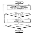
- FIG. 11 is a flowchart showing an example of the processing procedure in the approach mode.
- FIG. 12 is a flowchart showing an example of the processing procedure in the high altitude hovering mode.
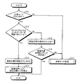
- FIG. 13 is a flowchart showing an example of the processing procedure in the low altitude hovering mode.
- FIG. 14 is a flowchart showing an example of the processing procedure in the landing mode.
- FIG. 15 is a flowchart showing an example of relative position calculation processing.
- FIG. 16 is a schematic configuration diagram showing an example of an automatic landing system for a vertical take-off and landing aircraft according to the second embodiment.
- FIG. 17 is a flowchart showing an example of the processing procedure of the high altitude hovering mode in the second embodiment.
- FIG. 18 is a flowchart showing an example of the processing procedure of the low altitude hovering mode in the second embodiment.
- FIG. 19 is a schematic configuration diagram showing an automatic landing system according to the third embodiment.
- FIG. 20 is a flowchart showing an example of the processing procedure of the high altitude hovering mode in the third embodiment.
- FIG. 21 is a flowchart showing an example of the processing procedure of the low altitude hovering mode in the third embodiment.
- FIG. 1 is a schematic configuration diagram showing an example of an automatic landing system for a vertical take-off and landing aircraft according to the first embodiment
- FIG. 2 is an explanation showing how the vertical take-off and landing aircraft according to the first embodiment heads for a landing target point. It is a figure.
- the vertical take-off and landing aircraft 1 according to the first embodiment is an air vehicle (for example, a helicopter, a drone, etc.) as a rotary wing aircraft.
- the vertical take-off and landing aircraft 1 is an unmanned aerial vehicle.
- the vertical take-off and landing aircraft 1 may be a manned aircraft as long as it is an air vehicle capable of moving forward, backward, laterally, turning, and hovering.
- the flight control based on the remote manual control is prioritized when the remote manual control is executed during the flight control of the unmanned aerial vehicle by the autopilot.
- the flight control based on the manual maneuver is prioritized when the manual maneuver is executed during the flight control of the manned aircraft by the autopilot.
- the vertical takeoff and landing aircraft 1 is equipped with an automatic landing system 100, and the flight is controlled by the automatic landing system 100 to land at the landing target point 2 shown in FIG.
- the landing target point 2 is provided on the ship 5 as shown in FIG. Therefore, the vertical take-off and landing aircraft 1 lands (més) on the ship 5 as a moving body that moves on the water.
- the landing target point 2 is not limited to the ship 5, and may be provided on a vehicle or the like as a moving body that moves on the ground, or may be provided on a non-moving facility or on the ground.
- the ship 5 is provided with a restraining device for restraining the vertical take-off and landing aircraft 1 when the vertical take-off and landing aircraft 1 is landed at the landing target point 2.
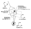
- FIG. 3 is an explanatory diagram showing each coordinate system of the automatic landing system.
- the ship inertial system SG which is the coordinate system in the ship 5
- the aircraft inertial system HG which is the coordinate system in the vertical takeoff and landing aircraft 1
- the camera fixed coordinate system C which is a system, is used.
- the ship inertial frame SG and the aircraft inertial frame HG are three-dimensional Cartesian coordinate systems including X-axis, Y-axis, and Z-axis.
- the camera fixed coordinate system C is a two-dimensional Cartesian coordinate system including an X axis and a Y axis.
- the aircraft is controlled with the center position (Sx, Sy) of the landing target point 2 as the origin, and in the case of the aircraft inertial frame HG , the position of the vertical takeoff and landing aircraft 1 as the origin.
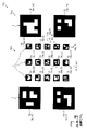
- FIG. 4 is an explanatory diagram showing an example of a marker group.
- FIG. 5 is an explanatory diagram showing an example of a marker included in the marker group. In FIG. 4, it is the position of the marker group 7G shown by the ship inertial system SG, and in FIG. 5, it is the position of the marker shown by the camera fixed coordinate system C.
- the marker group 7G includes a plurality of markers 7. As shown in FIG. 4, in the present embodiment, each marker 7 is, for example, an AR marker color-coded in two colors, black and white, and is a square marker.
- the marker 7 is not limited to the AR marker, and may be any marker that can acquire information for capturing the position of the landing target point 2 by image processing. Further, a plurality of marker groups 7G may be provided on the ship 5, and the vertical take-off and landing aircraft 1 may be guided to a landing target point 2 corresponding to any of the different marker groups 7G.
- the marker group 7G is configured to include a plurality of markers 7. More specifically, the marker group 7G includes a small marker group 72G and a large marker group 74G, as shown in FIG.
- the small marker group 72G includes a small marker 72 (for example, No. 1) provided at the landing target point 2 and a plurality of small markers 72 provided around the landing target point 2.
- the plurality of small markers 72 are arranged side by side so that their center positions are different from each other.
- No. The small marker 72 to be 1 is arranged so that its center position coincides with the center position (Sx, Sy) of the landing target point 2.
- No. The small markers 72 other than 1 are arranged so as to be offset from the center position from the landing target point 2.
- a plurality of small markers 72 are arranged in a matrix.
- FIG 3 shows an example in which a plurality of small markers 72 are arranged in 5 rows and 3 columns, but the number of rows and the number of columns are not particularly limited. Further, the plurality of small markers 72 do not need to be arranged in a matrix, and may be arranged scatteredly around the landing target point 2. That is, the distance between adjacent small markers 72 does not have to be constant.
- the large marker group 74G includes a plurality of large markers 74 having a size larger than that of the small marker 72.
- the large marker 74 is arranged side by side so that the center position is different from that of the small marker 72, and the center positions are different from each other.
- the large marker 74 is arranged off the center from the landing target point 2. Further, the large marker 74 is arranged at a position farther from the landing target point 2 than the small marker 72.
- the large marker 74 is arranged so as to surround the small marker group 72G with the landing target point 2 as the center. Then, in the large marker group 74G, the large markers 74 are arranged in a matrix. FIG.
- the large marker 74 is arranged in 2 rows and 2 columns, but the number of rows and the number of columns are not particularly limited. Further, the plurality of large markers 74 do not need to be arranged in a matrix, and may be arranged scatteredly at positions farther from the landing target point 2 than the small marker group 72G. That is, the distance between adjacent large markers 74 does not have to be constant.
- each marker 7 holds the information of the ID number as an AR marker.
- the ID number a different number is assigned to each of the markers 7.
- the ID number is assigned as smaller as the marker 7 closer to the landing target point 2.
- FIG. 4 shows an example of the ID number.
- the ID number of the small marker 72 arranged so as to coincide with the center of the landing target point 2 is set to "No. 1", and "No. 2" to "No. 15" are assigned to the small markers 72 around the small marker 72. Numbers up to, and numbers from "No. 16" to "No. 19" are assigned to the large marker 74.
- the ID numbers may be exchanged with each other.
- the ID numbers of the large markers 74 may be exchanged with each other. Further, the ID number may be assigned to a larger number as the marker 7 is closer to the landing target point 2.
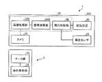
- the ship 5 includes a navigation device 70, a data transmission device 80, and an operation display unit 90.
- the navigation device 70 is, for example, an inertial navigation system (INS: Inertial Navigation System), and acquires attitude angles, bow orientations, speeds, accelerations, position coordinates, and the like in the pitch direction and roll direction of the ship 5.
- INS Inertial Navigation System
- the navigation device 70 will be described by applying it to an inertial navigation system, but the navigation device 70 is not particularly limited, and any navigation device 70 may be used.
- the navigation device 70 is an inertial navigation system including GPS (Global Positioning System) as a position measurement unit in order to improve the accuracy of position measurement.
- GPS Global Positioning System
- the description will be given by applying to an inertial navigation system including GPS, but the present invention is not particularly limited to GPS, and any position measuring unit capable of accurately measuring the position may be used, for example, a quasi-zenith satellite system is used. If the position can be measured accurately only by the navigation device 70, the position measurement unit such as GPS may be omitted. Further, the navigation device 70 may acquire at least a part of various data by a sensor.
- the data transmission device 80 is included in the automatic landing system 100 described later, and exchanges various signals with the data transmission device 40 mounted on the vertical takeoff and landing aircraft 1 by wireless communication.
- the operation display unit 90 is a user interface in which the operator on board the ship 5 grasps the control status and inputs various instructions.
- the instruction input by the operator by the operation display unit 90 includes, for example, a control mode transition instruction described later. The details of the migration instruction will be described later.
- the instruction input by the operation display unit 90 is transmitted from the data transmission device 80 to the data transmission device 40. Further, the control status of the vertical takeoff and landing aircraft 1 is transmitted from the data transmission device 40 to the data transmission device 80. That is, the data transmission device 40 and the data transmission device 80 are capable of bidirectional communication.
- the automatic landing system 100 of the vertical take-off and landing aircraft is a system that controls the position of the vertical take-off and landing aircraft 1 in order to land the vertical take-off and landing aircraft 1 in flight at the landing target point 2.
- the automatic landing system 100 is mounted on the vertical takeoff and landing aircraft 1.
- the automatic landing system 100 includes a camera 10, a navigation device 20, a control unit 30, and a data transmission device 40.
- the camera 10 is a photographing device mounted on the vertical take-off and landing aircraft 1 via a gimbal (not shown).
- the camera 10 may be a monocular camera, a compound eye camera, an infrared camera, or the like as long as the marker 7 can be photographed.
- the camera 10 is provided to photograph the marker 7 provided at the landing target point 2 from the vertical takeoff and landing aircraft 1.
- the camera 10 is capable of adjusting the shooting direction via a gimbal (not shown).
- the camera 10 is controlled by the control unit 30 so that the shooting range (angle of view) B (see FIG. 2) of the camera 10 faces directly below in the vertical direction, for example.
- the camera 10 may be controlled by the control unit 30 so that the shooting range B faces diagonally forward with respect to the vertical direction. Further, the camera 10 may omit the gimbal, and may be fixed directly below the body of the vertical take-off and landing aircraft 1 so that the shooting direction faces, for example, the lower side in the vertical direction.
- the control unit 30 acquires an image taken by the camera 10 in the camera fixed coordinate system C.
- the navigation device 20 is an inertial navigation system including, for example, a GPS.
- the navigation device 20 may be an inertial navigation system including a position measuring unit such as GPS, or an inertial navigation system omitting a position measuring unit such as GPS, as in the navigation device 70.
- the navigation device 20 including the GPS acquires the attitude angles in the pitch direction and the roll direction of the vertical takeoff and landing aircraft 1, the heading, the aircraft speed of the vertical takeoff and landing aircraft 1, the aircraft acceleration, the position coordinates, and the like.
- the navigation device 20 includes an attitude angle sensor that detects the attitude angle of the vertical takeoff and landing aircraft 1, a speed detection sensor that detects the aircraft speed of the vertical takeoff and landing aircraft 1, an acceleration detection sensor that detects the aircraft acceleration of the vertical takeoff and landing aircraft 1, and vertical. It may have a sensor for detecting the nose direction of the takeoff and landing aircraft 1.
- the navigation device 20 outputs the acquired attitude angle, aircraft speed, aircraft acceleration, and position coordinates of the vertical takeoff and landing aircraft 1 to the control unit 30.
- the automatic landing system 100 includes an altitude sensor 25 that detects the altitude of the vertical takeoff and landing aircraft 1 from the ground surface or the water surface.
- the altitude sensor 25 is, for example, a laser altimeter, and measures the relative altitude ⁇ h (see FIG. 2) from the vertical takeoff and landing aircraft 1 to the landing target point 2.
- a radio wave altimeter may be used, a barometric altimeter may be used, or any altimeter may be used. Further, these altimeters may be appropriately combined and applied according to the usage environment, that is, in order to measure the altitude from the ground surface and the altitude from the sea surface.
- the altitude sensor 25 outputs the detected relative altitude ⁇ h of the vertical takeoff and landing aircraft 1 to the control unit 30.
- the altitude sensor 25 measures the altitude of the vertical take-off and landing aircraft 1 and outputs it to the control unit 30, and the control unit 30 in the guidance calculation unit 34 described later, based on the altitude of the vertical take-off and landing aircraft 1, the landing target point.
- Relative altitude ⁇ h up to 2 may be calculated.
- the automatic landing system 100 is not limited to the altitude sensor 25, but the image processing unit 32 described later performs image processing on the image including the marker 7 taken by the camera 10, so that the vertical takeoff and landing aircraft 1 and the ship 5 can be combined with each other.
- the relative altitude ⁇ h may be calculated.
- the control unit 30 includes an image processing unit 32, a guidance calculation unit 34, and a flight control unit 36.
- the control unit 30 includes a shooting control unit (not shown) that controls the shooting direction of the camera 10 via a gimbal (not shown) provided on the vertical take-off and landing aircraft 1.
- the shooting range B of the camera 10 is adjusted so as to face directly below in the vertical direction.
- the image processing unit 32 performs image processing on the image taken by the camera 10 to calculate the center positions (see FIG. 5) of the small marker 72 and the large marker 74.
- the center position (Cx, Cy) here is a coordinate point in the camera fixed coordinate system C having the center of the image taken by the camera 10 as the origin, and can be calculated from the number of pixels from the center of the image. Specifically, as shown in FIG.
- the image processing unit 32 identifies two diagonal lines Ld extending between the corners of the small marker 72 by image processing, and the intersection of the two specified diagonal lines Ld is the center position. Let it be (Cx, Cy).
- the landing target point 2 is not limited to the center position of the small marker 72, and may be any of the four corners of the small marker 72 or may be a position offset from the center position of the small marker 72.
- the image processing unit 32 may specify only one diagonal line Ld and set the center position of the length of the specified diagonal line Ld as the center position (Cx, Cy). Further, the image processing unit 32 may specify two or more diagonal lines Ld and set a position that is the average of the center positions of the specified diagonal lines Ld as the center position (Cx, Cy). Further, the image processing unit 32 may calculate the center position (Cx, Cy) of the square based on the function when the small square marker 72 is trapezoidally corrected by using the function by the projective transformation. At that time, even if the keystone correction is performed using the coordinate points of the four corners of the small marker 72 or the coordinate points of each point of the boundary color-coded in black and white of the small marker 72, the other coordinate points are calculated by interpolation. good.
- small markers 72 having ID numbers “No. 2”, “No. 8”, “No. 10”, and “No. 14” are included in the image.
- the image processing unit 32 calculates the center position (Cx', Cy') of the small marker 72 by using the marker 7 having the smallest ID number among the recognized plurality of markers 7.
- the center position (Cx', Cy') of the small marker 72 is calculated using the small marker 72 of "No. 2" having the smallest ID number.
- the method for calculating the center position (Cx', Cy') of the small marker 72 is the same as the method for calculating the center of the small marker 72 described above.
- the center position of the small marker 72 is the coordinates ( Sx ', Sy'), and the landing target point 2 is the coordinates (Sx, Sy). It has become.
- the relative positional relationship between the landing target point 2 and the center position (Sx', Sy') of the small marker 72, that is, the distance is (Dx, Dy).
- the example shown in FIG. 8 is a case where the altitude of the vertical take-off and landing aircraft 1 is higher than the example shown in FIG. 5, and the ID numbers are “No. 2”, “No. 8”, “No. 10”, and “No. 10”.
- the small marker 72 of "14" and the large marker 74 of the ID number "No. 18" are reflected in the image.
- the image processing unit 32 cannot recognize each small marker 72 due to the small size of each small marker 72 in the image, and can recognize only the large marker 74.
- the center position of the large marker 74 is the coordinates ( Sx ′′, Sy ′′), and the landing target point 2 is the coordinates (Sx, Sy).
- the relative positional relationship between the landing target point 2 and the center position (Sx ′′, Sy ′′) of the large marker 74, that is, the distance (hereinafter, also referred to as an offset amount) is (Dx, Dy).
- the method of calculating the center position of the large marker 74 in the camera fixed coordinate system C is the same as the method of calculating the center of the small marker 72 described above.
- the image processing unit 32 calculates the relative altitude ⁇ h between the vertical takeoff and landing aircraft 1 and the ship 5 by performing image processing on the image including the marker 7 taken by the camera 10. May be good. Further, the image processing unit 32 identifies the direction of the marker 7 by performing image processing on the image including the marker 7 taken by the camera 10, and sets the heading of the vertical takeoff and landing aircraft 1 acquired by the navigation device 20. By associating, the heading direction of the ship 5 may be calculated. A marker for calculating the bow direction may be separately provided on the ship 5.
- the guidance calculation unit 34 calculates the control amount of the vertical take-off and landing aircraft 1 for guiding the vertical take-off and landing aircraft 1 to the landing target point 2.
- the control amount is a control amount for adjusting the airframe speed, attitude angle, change rate of attitude angle, etc. of the vertical takeoff and landing aircraft 1.
- the guidance calculation unit 34 calculates the relative position (X, Y) between the vertical takeoff and landing aircraft 1 and the landing target point 2 and the relative speed between the vertical takeoff and landing aircraft 1 and the landing target point 2 in order to calculate the control amount.
- the guidance calculation unit 34 has the center positions (Cx', Cy') and (Cx', Cy'') of the small marker 72 or the large marker 74 calculated by the image processing unit 32, and the orientation of the camera 10, that is, vertical takeoff and landing. Vertical based on the nose direction of the aircraft 1, the altitude of the vertical takeoff and landing aircraft 1 (relative altitude ⁇ h with respect to the landing target point 2), and the offset amount (Dx, Dy) of the markers 72 and 74 with respect to the landing target point 2. The relative positions (X, Y) between the takeoff and landing aircraft 1 and the landing target point 2 are calculated.
- the orientation of the camera 10 and the heading of the vertical takeoff and landing aircraft 1 are matched, but the orientation is not particularly limited, and the orientation of the camera 10 and the heading of the vertical takeoff and landing aircraft 1 are not matched. You may.
- the image processing unit 32 and the guidance calculation unit 34 function as a relative position acquisition unit that acquires the relative position between the vertical takeoff and landing aircraft 1 and the landing target point 2.
- the relative position (X, Y) is the distance between the vertical takeoff and landing aircraft 1 and the landing target point 2 in the horizontal direction.
- the guidance calculation unit 34 uses the center positions (Cx', Cy'), (Cx', Cy') of the small marker 72 or the large marker 74 in the camera fixed coordinate system C calculated by the image processing unit 32.
- ⁇ is the center of the vertical take-off and landing aircraft 1 and the markers 72 and 74 in the ship inertial frame SG based on the nose orientation of the vertical take-off and landing aircraft 1 and the altitude of the vertical take-off and landing aircraft 1 (relative altitude ⁇ h with respect to the landing target point 2).
- the ship inertia It is converted into a relative position ( X , Y) between the vertical take-off and landing aircraft 1 and the landing target point 2 in the system SG.
- the guidance calculation unit 34 makes landing with the vertical take-off and landing aircraft 1 in the aircraft inertial system HG based on the nose direction of the vertical take-off and landing aircraft 1 and the altitude of the vertical take-off and landing aircraft 1 (relative altitude ⁇ h with respect to the landing target point 2). It may be directly converted to a relative position (X, Y) with the target point 2.
- the ship inertial frame SG is a coordinate system with the landing target point 2 as the origin, the direction along the bow direction of the ship 5, the direction orthogonal to the head direction of the ship 5 in the horizontal direction, and the vertical direction as the orthogonal axis. be. Further, as shown in FIGS.
- the aircraft inertial system HG has the vertical takeoff and landing aircraft 1 as the origin, the X-axis in the direction along the nose direction of the vertical takeoff and landing aircraft 1, and the nose of the vertical takeoff and landing aircraft 1. It is a coordinate system in which the direction orthogonal to the azimuth in the horizontal direction is the Y axis and the vertical direction is the Z axis.
- the guidance calculation unit 34 has the position coordinates in the earth coordinate system of the vertical takeoff and landing machine 1 acquired by the navigation device 20 and the position coordinates acquired by the navigation device 70 of the ship 5 and obtained by communication of the data transmission devices 40 and 80.
- the relative position (X GPS , Y GPS ) between the vertical takeoff and landing aircraft 1 and the landing target point 2 is calculated based on the position coordinates of the ship 5 in the earth coordinate system. Therefore, the guidance calculation unit 34 is based on the position coordinates of the vertical takeoff and landing machine 1 acquired by GPS and the position coordinates of the ship 5 provided with the landing target point 2 acquired by the data transmission device 40. It functions as a second relative position acquisition unit that calculates the relative position (X GPS , Y GPS ) between 1 and the landing target point 2.
- the control unit 30 stores in advance the distance (Dx, Dy) from the center of each marker 7 to the landing target point 2 in a storage unit (not shown).
- the guidance calculation unit 34 is based on the center position (Cx', Cy') of the small marker 72 of "No. 2" calculated by the image processing unit 32.
- the relative position ( X ', Y') between the vertical takeoff and landing aircraft 1 and the center position (Sx', Sy') of the small marker 72 in the inertial frame SG is calculated.
- the guidance calculation unit 34 adds the distance (Dx, Dy) stored in advance to the calculated relative position ( X ', Y') as an offset amount, so that the vertical takeoff and landing aircraft in the ship inertial system SG
- the relative position (X, Y) between 1 and the center position (Sx, Sy) of the landing target point 2 is calculated.
- the small marker 72 No. 1
- it can be said that the distance (Dx, Dy) is 0.
- the small marker 72 (No. 1) is arranged so as to coincide with the center position (Sx, Sy) of the landing target point 2, but this configuration is not essential and all the small marker group 72G are landed. It may be composed of a small marker 72 shifted from the center position (Sx, Sy) of the target point 2.
- the guidance calculation unit 34 uses the large marker 74 of “No. 18” with the smallest ID number recognized in the image to determine the relative position between the vertical takeoff and landing aircraft 1 and the center position (Sx, Sy) of the landing target point 2.
- Calculate (X, Y) That is, as described above, the guidance calculation unit 34 and the vertical takeoff and landing aircraft 1 in the ship inertial frame SG are based on the center position (Cx ′′, Cy ′′) of the large marker 74 calculated by the image processing unit 32.
- the relative position (X', Y') with the center position (Sx', Sy') of the large marker 74 is calculated.
- the guidance calculation unit 34 adds the distance (Dx, Dy) stored in advance to the calculated relative position (X', Y') as an offset amount, so that the vertical takeoff and landing aircraft 1 and the landing target point 2 are added.
- the relative position (X, Y) with respect to the center position (Sx, Sy) of is calculated.
- the relative calculation method offsets to the center position (Sx, Sy) of the landing target point 2 by the above calculation method.
- the position (X, Y) can be calculated.
- the relative position (X, Y) can be calculated based on the marker 7 photographed by the camera 10. That is, when calculating the relative position (X, Y), it is not necessary to perform data communication with the ship 5 side. As a result, when the vertical take-off and landing aircraft 1 is controlled based on the relative position (X, Y), it is not affected by errors due to the navigation devices 20 and 70, so that the position accuracy can be improved and the communication can be performed. It is possible to suppress the deterioration of the responsiveness of the flight control due to the above. Therefore, the vertical take-off and landing aircraft 1 can be landed at the landing target point 2 with higher accuracy. Then, by accurately controlling the position of the vertical take-off and landing aircraft 1 with respect to the landing target point 2, it is possible to prevent the vertical take-off and landing aircraft 1 from interfering with devices and structures provided in the vicinity of the landing target point 2. Can be done.
- the guidance calculation unit 34 calculates the relative speed between the vertical takeoff and landing aircraft 1 and the landing target point 2. Therefore, the guidance calculation unit 34 functions as a relative speed acquisition unit that acquires the relative speed between the vertical takeoff and landing aircraft 1 and the landing target point 2. More specifically, the guidance calculation unit 34 calculates the relative speed from, for example, the difference between the hull speed of the vertical takeoff and landing aircraft 1 acquired by the navigation devices 20 and 70 and the hull speed of the ship 5. Further, the induction calculation unit 34 may calculate the relative velocity based on the pseudo-differentiation of the relative position (X, Y). Further, the guidance calculation unit 34 calculates the relative direction between the heading of the vertical take-off and landing aircraft 1 and the heading of the ship 5.
- the guidance calculation unit 34 calculates the relative altitude ⁇ h up to the landing target point 2 based on the altitude of the vertical takeoff and landing aircraft 1 detected by the altitude sensor 25. Therefore, the altitude sensor 25 and the guidance calculation unit 34 function as a relative altitude acquisition unit that acquires the relative altitude ⁇ h between the vertical takeoff and landing aircraft 1 and the landing target point 2.
- the image processing unit 32 performs image processing on the image including the marker 7 taken by the camera 10 to calculate the relative altitude ⁇ h between the vertical takeoff and landing aircraft 1 and the ship 5
- the image processing unit 32 is relative. It becomes the altitude acquisition department.
- the guidance calculation unit 34 calculates the control amount by feedback control (for example, PID control) based on the relative position (X, Y), relative velocity, relative direction, and aircraft acceleration.
- the guidance calculation unit 34 calculates the control amount of the vertical takeoff and landing aircraft 1 by feedback control so that the relative position (X, Y) and the relative direction become zero.
- the guidance calculation unit 34 may calculate the control amount of the vertical takeoff and landing aircraft 1 by feedback control so that the relative speed is within the predetermined speed and the aircraft acceleration is within the predetermined acceleration. Within a predetermined speed and within a predetermined acceleration, the range is such that the vertical take-off and landing aircraft 1 can be said to be able to fly stably at a predetermined relative altitude ⁇ h.
- the predetermined velocity is zero
- the predetermined acceleration is zero
- the guidance calculation unit 34 outputs the calculated control amount to the flight control unit 36.
- the guidance calculation unit 34 controls the vertical take-off and landing aircraft 1 in a plurality of control modes in order to guide the vertical take-off and landing aircraft 1 to the landing target point and land.
- the plurality of control modes include an approach mode, a hovering mode including a high altitude hovering mode and a low altitude hovering mode, and a landing mode. Details of each control mode will be described later.
- the automatic landing system 100 controls so that the relative position (X, Y) becomes zero, but in reality, the relative position includes an error after the vertical takeoff and landing aircraft 1 lands on the ship 5. It does not always reach zero, and the positions of the vertical takeoff and landing aircraft 1 and the landing target point 2 do not completely match.
- the flight control unit 36 controls each component of the vertical take-off and landing aircraft 1 according to the control amount calculated by the guidance calculation unit 34, which will be described later, to fly the vertical take-off and landing aircraft 1.
- the flight control unit 36 controls the blade pitch angle, rotation speed, etc. of each rotor according to the controlled amount, and adjusts the airframe speed, attitude angle, change rate of attitude angle, etc. of the vertical takeoff and landing aircraft 1.
- the vertical take-off and landing aircraft 1 is guided to the landing target point 2.
- the image processing unit 32 and the guidance calculation unit 34 are described as functional units different from the flight control unit 36, but the flight control unit 36, the image processing unit 32, and the guidance calculation unit 34 are integrated. It may be a functional unit. That is, the flight control unit 36 may process the image processing unit 32 and the guidance calculation unit 34.
- FIG. 9 is a flowchart showing an example of a processing procedure of the landing control method of the vertical take-off and landing aircraft according to the first embodiment.
- FIG. 10 is an explanatory diagram showing the landing operation of the vertical take-off and landing aircraft according to the first embodiment.
- FIG. 11 is a flowchart showing an example of the processing procedure in the approach mode.
- FIG. 12 is a flowchart showing an example of the processing procedure in the high altitude hovering mode.
- FIG. 13 is a flowchart showing an example of the processing procedure in the low altitude hovering mode.
- FIG. 14 is a flowchart showing an example of the processing procedure in the landing mode.
- FIG. 15 is a flowchart showing an example of relative position calculation processing. The processes shown in FIGS. 9 to 15 are executed by the guidance calculation unit 34.
- the vertical take-off and landing aircraft 1 executes a plurality of control modes in a series of landing operations for landing (landing) on a ship 5 from a flight state.
- the vertical take-off and landing aircraft 1 has a step S1 for executing the approach mode, a step S2 for executing the high altitude hovering mode, a step S3 for executing the low altitude hovering mode, and a step S4 for executing the landing mode.
- a series of landing operations are performed.
- the vertical take-off and landing aircraft 1 performs a step (step S17 described later) of interrupting the execution of the high altitude hovering mode and the low altitude hovering mode and executing the emergency mode in which the landing operation is interrupted.
- the approach mode is a mode in which the vertical take-off and landing aircraft 1 is made to enter the deck of the ship 5 and the vertical take-off and landing aircraft 1 is hovered on the landing target point 2 by a command from the ship 5.
- the vertical takeoff and landing aircraft 1 captures the marker group 7G on the deck with the camera 10, and the landing target point 2 is hovering so as to be in the center of the shooting range (angle of view) B of the camera 10. It has become.
- the low altitude hovering mode is a mode in which the vertical takeoff and landing aircraft 1 descends and hovering at a lower altitude than the high altitude hovering mode.
- the landing mode is a mode in which the vertical takeoff and landing aircraft 1 lands at the landing target point 2.
- the emergency mode is a mode in which the landing operation of the vertical take-off and landing aircraft 1 on the ship 5 is interrupted and the ship rises.
- the vertical take-off and landing aircraft 1 executes a landing operation on the ship 5 by executing these control modes. Next, each control mode will be specifically described with reference to FIGS. 11 to 15.
- the guidance calculation unit 34 executes the approach mode as step S1.
- the approach mode will be described in detail with reference to FIG.
- the guidance calculation unit 34 calculates (generates) relative positions (X GPS , Y GPS ) from the navigation devices 20, 70, that is, the position coordinates obtained by GPS.
- the guidance calculation unit 34 determines whether or not the approach mode button is turned on as step S32.
- the approach mode button is a button for inputting a control mode transition instruction provided on the operation display unit 90 of the ship 5, and is turned on and off by an operator on board the ship 5. The operator turns on the approach mode button when the vertical take-off and landing aircraft 1 is ready to land on ship 5.
- the control unit 30 determines that the approach mode button is not turned on (No in step S32)
- the control unit 30 continues the process of step S1.
- the control unit 30 determines that the approach mode button is on (Yes in step S32)
- the control unit 30 proceeds to the process of step S33.
- step S33 the guidance calculation unit 34 executes feedback control so that the relative position (X GPS , Y GPS ) generated in step S31 becomes zero.
- the guidance calculation unit 34 causes the vertical takeoff and landing aircraft 1 to fly toward the landing target point 2 in the horizontal direction.
- the guidance calculation unit 34 executes feedback control so that the calculated relative direction between the heading of the vertical take-off and landing aircraft 1 and the heading of the ship 5 becomes zero as an example.
- the guidance calculation unit 34 makes the vertical takeoff and landing aircraft 1 fly so that the heading of the vertical takeoff and landing aircraft 1 coincides with the heading of the ship 5.
- the guidance calculation unit 34 executes feedback control so that the relative direction becomes zero, but the relative direction is not particularly limited and may not be zero.
- the guidance calculation unit 34 executes feedback control so that the relative altitude ⁇ h measured by the altitude sensor 25 becomes the first relative altitude ⁇ h1.
- the guidance calculation unit 34 keeps the vertical takeoff and landing aircraft 1 at the first relative altitude ⁇ h1 while descending from the initial altitude to the first relative altitude ⁇ h1 (see FIG. 2) in the vertical direction.
- the first relative altitude ⁇ h1 is, for example, 20 m.
- the vertical take-off and landing aircraft 1 is controlled so that the relative position (X GPS , Y GPS ) becomes zero so that the vertical take-off and landing aircraft 1 is within a predetermined range of the landing target point 2. Is in flight control.
- the guidance calculation unit 34 executes the image relative position calculation process as step S34, and calculates the relative position (X, Y) as the horizontal distance between the vertical takeoff and landing aircraft 1 and the landing target point 2. The details of the image relative position calculation process will be described later.
- step S35 the guidance calculation unit 34 determines whether the relative position (X, Y) as the horizontal distance between the vertical takeoff and landing aircraft 1 and the landing target point 2 calculated in step S34 is within the first threshold value. Judge whether or not.
- the first threshold value is set by the camera 10 as a value sufficient to keep capturing the landing target point 2.
- the guidance calculation unit 34 re-executes the processes after step S33. That is, the vertical take-off and landing aircraft 1 cannot capture the landing target point 2 by the camera 10, in other words, it is assumed that the landing target point 2 is not sufficiently close to the landing target point 2, and the processes after step S33 are executed again.
- the guidance calculation unit 34 repeatedly executes the processes after step S33 until the vertical take-off and landing aircraft 1 reaches a distance sufficient for the camera 10 to continue to capture the landing target point 2.
- the guidance calculation unit 34 determines that the relative position (X, Y) is within the first threshold value (Yes in step S35)
- the vertical takeoff and landing aircraft 1 continues to capture the landing target point 2 by the camera 10. It is assumed that the distance is sufficient, that is, the landing target point 2 is sufficiently close to the landing target point 2, and the approach mode is terminated and the next control mode is started.
- the high altitude hovering mode is executed as step S2.
- the high altitude hovering mode will be described in detail with reference to FIG.
- the guidance calculation unit 34 executes feedback control so that the relative position (X, Y) calculated by the image relative position calculation process becomes zero, as shown in step S41 of FIG. .. Further, the guidance calculation unit 34 executes feedback control so that the calculated relative direction between the heading of the vertical take-off and landing aircraft 1 and the heading of the ship 5 becomes zero as an example. Further, the guidance calculation unit 34 executes feedback control so that the relative altitude ⁇ h measured by the altitude sensor 25 becomes the first relative altitude ⁇ h1.
- the guidance calculation unit 34 keeps the vertical takeoff and landing aircraft 1 at the first relative altitude ⁇ h1 while hovering just above the landing target point 2 in the vertical direction. Then, the guidance calculation unit 34 executes the image relative position calculation process again in step S42.
- step S43 the guidance calculation unit 34 determines whether or not the relative position (X, Y) calculated in step S42 is within the second threshold value, and whether or not the low altitude hovering mode button is turned on.
- the second threshold value is set as a value that is equal to or less than the first threshold value in the approach mode.
- the low altitude hovering mode button is a button for inputting a control mode transition instruction provided on the operation display unit 90 of the ship 5, and is turned on and off by an operator on board the ship 5.
- Step S43 determines whether or not the first condition for shifting from the high altitude hovering mode to the low altitude hovering mode is satisfied. That is, in the first embodiment, the first condition includes that the relative position (X, Y) is within the second threshold value and that the operator has instructed the mode to shift to the low altitude hovering mode. ..
- the guidance calculation unit 34 determines that the relative position (X, Y) is not within the second threshold value (No in step S43). Further, even when the guidance calculation unit 34 determines that the low altitude hovering mode button is not turned on (No in step S43), the process after step S41 is executed again. Then, the guidance calculation unit 34 repeatedly executes the processes after step S41 until the vertical takeoff and landing aircraft 1 has a relative position (X, Y) with respect to the landing target point 2 within the second threshold value. When the guidance calculation unit 34 determines that the relative position (X, Y) is within the second threshold value and the low altitude hovering mode button is turned on (Yes in step S43), the high altitude hovering mode And move to the next control mode.
- the guidance calculation unit 34 executes the low altitude hovering mode as step S3.
- the low altitude hovering mode will be described in detail with reference to FIG.
- the guidance calculation unit 34 executes feedback control so that the relative position (X, Y) calculated by the image relative position calculation process becomes zero, as shown in step S51 of FIG. ..
- the guidance calculation unit 34 executes feedback control so that the calculated relative direction between the heading of the vertical take-off and landing aircraft 1 and the heading of the ship 5 becomes zero as an example.
- the guidance calculation unit 34 feedback-controls so that the relative altitude ⁇ h measured by the altitude sensor 25 becomes the second relative altitude ⁇ h2 lower than the first relative altitude ⁇ h1. As a result, the guidance calculation unit 34 lowers the altitude of the vertical takeoff and landing aircraft 1 to the second relative altitude ⁇ h2 (see FIG. 2) while hovering the vertical takeoff and landing aircraft 1 immediately above the landing target point 2.
- the second relative altitude ⁇ h2 is, for example, 3 m.
- the guidance calculation unit 34 sets the descent speed of the vertical takeoff and landing aircraft 1 as the first descent speed.
- the first descent speed is, for example, 0.6 m / s. Then, the guidance calculation unit 34 executes the image relative position calculation process again in step S52.
- step S53 the guidance calculation unit 34 determines whether or not the relative position (X, Y) calculated in step S52 is within the third threshold value (predetermined threshold value), and the landing mode button is turned on. Determine if it is.
- the third threshold value is set as a value that is equal to or less than the second threshold value in high altitude hovering.
- the landing mode button is a button for inputting a control mode transition instruction provided on the operation display unit 90 of the ship 5, and is turned on and off by an operator on board the ship 5. The operator visually confirms whether the vertical take-off and landing aircraft 1 is able to fly stably at the second relative altitude ⁇ h2, and turns on the landing mode button when the vertical take-off and landing aircraft 1 is able to fly stably. ..
- Step S53 determines whether or not the second condition (predetermined condition) for shifting from the low altitude hovering mode to the landing mode is satisfied. That is, in the first embodiment, the second condition includes that the relative position (X, Y) is within the third threshold value and that the operator has instructed the mode transition to the landing mode. The operator may turn on the landing mode button even when the vertical take-off and landing aircraft 1 is not stable.
- the guidance calculation unit 34 determines that the relative position (X, Y) is not within the third threshold value (No in step S53). Further, even when the guidance calculation unit 34 determines that the landing mode button is not turned on (No in step S53), the process after step S51 is executed again. Then, the guidance calculation unit 34 causes the vertical take-off and landing aircraft 1 to descend to the second relative altitude ⁇ h2 while the position (X, Y) relative to the landing target point 2 is within the third threshold value. In addition, the processes after step S51 are repeatedly executed.
- the guidance calculation unit 34 determines that the relative position (X, Y) is within the third threshold value and the landing mode button is turned on (Yes in step S53), the guidance calculation unit 34 ends the low altitude hovering mode. Then, it shifts to the next control mode.
- the guidance calculation unit 34 executes the landing mode as step S4.
- the landing mode will be described in detail with reference to FIG.
- the guidance calculation unit 34 executes feedback control so that the relative position (X, Y) calculated by the image relative position calculation process becomes zero.
- the guidance calculation unit 34 executes feedback control so that the calculated relative direction between the heading of the vertical take-off and landing aircraft 1 and the heading of the ship 5 becomes zero as an example.
- the guidance calculation unit 34 executes vertical speed control in which the descent rate is constant until the relative altitude ⁇ h measured by the altitude sensor 25 becomes the third relative altitude ⁇ h3.
- the descent rate is the degree of altitude that descends per unit time.
- the guidance calculation unit 34 uses the descent speed of the vertical takeoff and landing aircraft 1 as the second descent speed. As a result, the guidance calculation unit 34 lowers the relative altitude ⁇ h of the vertical takeoff and landing aircraft 1 to the third relative altitude ⁇ h3 (see FIG. 2).
- the third relative altitude ⁇ h3 is, for example, 10 cm.
- the second descent speed is, for example, 1.0 m / s.
- the second descent speed is set to be larger than the first descent speed, but the first descent speed and the first descent speed are set.
- the descent speed may be set to a large value or may be the same value. Further, when the altitude of the vertical take-off and landing aircraft 1 reaches the third relative altitude ⁇ h3, the guidance calculation unit 34 keeps the control amount regarding the attitude angle of the vertical take-off and landing aircraft 1 when the altitude reaches the third relative altitude ⁇ h3. Further lower the vertical takeoff and landing aircraft 1. It should be noted that not only the attitude angle but also the control amounts related to the relative position (X, Y), the relative direction, and the relative velocity are all held, not all held, or partially held. , The vertical takeoff and landing aircraft 1 may be landed at the landing target point 2.
- step S62 the guidance calculation unit 34 determines whether or not the camera 10 has captured at least one marker 7, that is, whether or not the landing target point 2 has been captured. Whether or not at least one marker 7 can be captured by the camera 10 can be calculated by the same processing as in step S12 of the image relative position calculation processing described later.
- the guidance calculation unit 34 calculates the relative position (X, Y) by image processing in step S63.
- the relative positions (X, Y) can be calculated by the same processing as in step S14 of the image relative position calculation processing described later.
- step S63 is omitted and the process proceeds to step S64.
- the execution of the landing mode may be interrupted based on the judgment of the pilot during the execution of the landing mode.
- the flight control unit 36 determines in step S64 whether or not the vertical takeoff and landing aircraft 1 has landed at the landing target point 2. Whether or not the vertical take-off and landing aircraft 1 has landed at the landing target point 2 can be determined, for example, by providing a contact-type sensor on a leg (not shown) of the vertical take-off and landing aircraft 1.
- the flight control unit 36 executes the processes after step S61 again. As a result, the vertical take-off and landing aircraft 1 is controlled to descend by the procedure of step S61 until the vertical take-off and landing aircraft 1 lands at the landing target point 2.
- step S64 when the flight control unit 36 determines that the vertical takeoff and landing aircraft 1 has landed at the landing target point 2 (Yes in step S64), the guidance calculation unit 34 ends the landing mode. As a result, the processing routine shown in FIG. 9 is also terminated.
- the guidance calculation unit 34 determines in step S11 whether or not the emergency mode button is turned off.
- the emergency mode button is provided on the operation display unit 90 of the ship 5, and is turned on and off by an operator on board the ship 5.
- the emergency mode button is turned on. Specifically, the operator turns on the emergency mode button when it is visually confirmed that the flight state of the vertical take-off and landing aircraft 1 is unstable due to, for example, the influence of wind or the occurrence of some kind of failure.
- step S11 When the guidance calculation unit 34 determines in step S11 that the emergency mode button is turned on (No in step S11), the guidance calculation unit 34 shifts to the execution of the emergency mode as step S17.
- the guidance calculation unit 34 raises the vertical take-off and landing aircraft 1 to a predetermined altitude (for example, 20 m) sufficiently away from the ship 5 to maintain the current relative position (X, Y).
- the guidance calculation unit 34 can execute the emergency mode during the execution of step S2 for executing the high altitude hovering mode shown in FIG. 9 and step S3 for executing the low altitude hovering mode.
- the guidance calculation unit 34 restarts the process shown in FIG. 9 from step S1.
- the guidance calculation unit 34 determines whether or not at least one marker 7 can be captured by the camera 10 in step S12. Whether or not at least one marker 7 can be captured by the camera 10 is determined by the center position (Cx', Cy'), (Cx',', of the small marker 72 or the large marker 74 in the image taken by the camera 10. It can be determined whether or not information that can calculate Cy ′′) is obtained. That is, it can be determined whether or not at least one of the plurality of markers 7 included in the marker group 7G can be recognized by image processing within the range of the image captured by the camera 10.
- the guidance calculation unit 34 determines that the camera 10 has captured at least one marker 7 (Yes in step S12), the target non-capture counter is set to a value of 0 in step S13. Then, as step S14, the guidance calculation unit 34 sets the center position (Cx', Cy'), (Cx', Cy'') of the small marker 72 or the large marker 74 and the orientation of the camera 10 (that is, the same orientation).
- the relative position (X, Y) between the vertical take-off and landing aircraft 1 and the landing target point 2 is calculated based on.
- the relative positions (X, Y) are the center positions (Cx ′, Cy ′), (Cx ′′ ′ ′) of the small marker 72 or the large marker 74 in the camera fixed coordinate system C calculated by the image processing unit 32. , Cy ′′), the relative position ( X ′, ′ ′′) of the vertical take-off and landing aircraft 1 and the center positions (Sx ′, Sy ′), (Sx ′′, Sy ′′) of the markers 72 and 74 in the ship inertial frame SG.
- step S12 determines in step S12 that the camera 10 has not captured any of the markers 7 (No in step S12)
- the guidance calculation unit 34 adds a value 1 to the target non-capture counter as step S15.
- step S16 it is determined whether or not the target non-capture counter is within a predetermined value.
- the guidance calculation unit 34 executes the processing after step S11 again (the processing of FIG. 15 is executed again).
- the guidance calculation unit 34 determines that the target non-capture counter is not within the predetermined value (No in step S16)
- the process proceeds to step S17, and the process proceeds to the execution of the emergency mode. That is, the guidance calculation unit 34 determines that the time during which even one marker 7 cannot be continuously captured by the camera 10 has reached a predetermined time or longer because the target non-capture counter exceeds a predetermined value, and executes the emergency mode.
- the automatic landing system 100 of the vertical take-off and landing aircraft includes a camera 10 (photographing device) mounted on the vertical take-off and landing aircraft 1 and a marker provided at the landing target point 2 by the camera 10.
- An image processing unit 32 and a guidance calculation unit 34 that perform image processing on the image taken of the group 7G and acquire the relative positions (X, Y) between the vertical takeoff and landing aircraft 1 and the landing target point 2.
- a control unit 30 for controlling the vertical take-off and landing aircraft 1 so that the relative positions (X, Y) become zero is provided, and the marker group 7G includes a plurality of markers 7 provided side by side at different center positions from each other.
- the marker 7 is larger as it is located farther from the landing target point 2, and the image processing unit 32 and the guidance calculation unit 34 are the distance between the marker 7 recognized in the image and the landing target point 2 (Dx, The relative position (X, Y) is acquired based on Dy).
- the landing target point 2 when the landing target point 2 is provided on a moving body such as a ship 5, the moving body is shaken, or a gust is generated around the vertical takeoff and landing machine 1. Even if the above occurs, it becomes easy to capture any one of the plurality of markers 7 included in the marker group 7G in the image. Further, since the marker 7 is as large as the marker 7 placed at a position away from the landing target point 2, even when the altitude of the vertical takeoff and landing aircraft 1, that is, the distance to the marker group 7G is relatively large, the marker 7 having a large size is imaged. It will be easier to recognize within. Therefore, the landing target point 2 can be captured more stably from the vertical take-off and landing aircraft 1.
- the vertical take-off and landing aircraft 1 the automatic landing system 100 of the vertical take-off and landing aircraft 1, and the automatic landing method of the vertical take-off and landing aircraft 1, the vertical take-off and landing aircraft 1 can be more stably moved to the landing target point 2. It becomes possible to induce.
- the marker group 7G includes a small marker 72 and a large marker 74 arranged at a position farther from the landing target point 2 than the small marker 72.
- the marker group 7G may include the markers 7 having three or more sizes. In that case, it is preferable that the larger marker 7 is arranged at a position farther from the landing target point 2. Further, the marker group 7G may be composed of only a marker 7 having a single size.
- a different ID number is assigned to each marker 7, and the image processing unit 32 and the guidance calculation unit 34 acquire the ID number from the marker 7 recognized in the image and correspond to the ID number.
- the relative position (X, Y) is acquired based on the distance (Dx, Dy) between the marker 7 stored in advance and the landing target point 2.
- the ID number is assigned as smaller as the marker 7 closer to the landing target point 2, and the image processing unit 32 and the guidance calculation unit 34 have the marker 7 with the smallest ID number recognized in the image and the landing target point 2.
- the relative position (X, Y) is acquired based on the distance (Dx, Dy) from. With this configuration, the marker 7 arranged at a position close to the landing target point 2 can be easily determined by the size of the ID number. Further, it is possible to accurately obtain a relative position (X, Y) offset to the center position (Sx, Sy) of the landing target point 2 based on the distance (Dx, Dy) between the marker 7 and the landing target point 2. It will be possible.
- a marker 7 closer to the landing target point 2 is assigned a larger number, and the image processing unit 32 and the guidance calculation unit 34 have the marker 7 with the largest ID number recognized in the image and the landing target point 2.
- the relative position (X, Y) may be acquired based on the distance (Dx, Dy) from.
- any marker 7 may be used, but it is preferable to preferentially use the marker 7 near the center of the image.
- the relative position (X, Y) offset to the center position (Sx, Sy) of the landing target point 2 can be calculated more accurately without being affected by the distortion in the vicinity of the image edge. ..
- the image processing unit 32 and the guidance calculation unit 34 calculate the relative position (X, Y) based on the distance (Dx, Dy) from the landing target point 2 for each of the markers 7 recognized in the image.
- the average value of all the calculated relative positions (X, Y) may be acquired as the final relative position (X, Y). More specifically, in the image processing unit 32, for each of the markers 7 recognized in the image, one by one, the relative position (X, Sy) offset to the center position (Sx, Sy) of the landing target point 2 by the above-mentioned method. Y) is calculated. Then, the average value of all the calculated relative positions (X, Y) is acquired as the final relative position (X, Y) at that time.
- the relative positions (X, Y) can be acquired more accurately based on all the markers 7 recognized in the image. Further, since all the markers 7 recognized in the image are used, it is not necessary to set in advance which marker 7 is preferentially used, and the ID number of each marker 7 can be arbitrarily set. Become.
- the marker 7 may hold information on the distance (Dx, Dy) from the landing target point 2 instead of the information on the ID number.
- the image processing unit 32 acquires information on the distance (Dx, Dy) from the landing target point 2 by image processing from any of the markers 7 recognized in the image, and the acquired distance (Dx, Dy). ), The relative position (X, Y) offset to the center position (Sx, Sy) of the landing target point 2 is calculated.
- any marker 7 may be used, but it is preferable to preferentially use the marker 7 close to the landing target point 2.
- FIG. 16 is a schematic configuration diagram showing an example of an automatic landing system for a vertical take-off and landing aircraft according to the second embodiment.
- the automatic landing system 200 according to the second embodiment has a configuration in which the data transmission device 40 is omitted from the automatic landing system 100.
- the automatic landing system 200 includes a guidance calculation unit 34A instead of the guidance calculation unit 34. Since the other configurations of the automatic landing system 200 are the same as those of the automatic landing system 100, the description thereof is omitted, and the same components are designated by the same reference numerals. Further, since the guidance calculation unit 34A has the same functions as the guidance calculation unit 34 except for the portion described below, the description of the same functions will be omitted.
- the ship 5 does not need to include the data transmission device 80 and the operation display unit 90.
- the navigation device 70 is omitted in FIG. 16 because it does not require the exchange of data acquired by the navigation device 70 between the vertical take-off and landing aircraft 1 and the ship 5.
- the automatic landing system 200 does not perform data communication with the ship 5 side. Therefore, when calculating the relative speed, the hull speed cannot be obtained from the ship 5. Therefore, in the second embodiment, the guidance calculation unit 34 calculates the relative speed based on the relative position (X, Y) between the vertical takeoff and landing aircraft 1 and the landing target point 2. Specifically, the induction calculation unit 34A calculates the relative velocity by pseudo-differentiating the relative positions (X, Y).
- the guidance calculation unit 34A does not execute the process of step S1 in the flowchart shown in FIG. 9, and takes off and landing vertically to the extent that the marker 7 is captured in the shooting range B of the camera 10 by another method. Bring the aircraft 1 closer to the vessel 5, that is, the landing target point 2.
- a laser irradiation device is mounted on the vertical take-off and landing aircraft 1, the laser is irradiated toward the ship 5, and the reflected wave is received on the vertical take-off and landing aircraft 1 side.
- a method of acquiring a relative position with the ship 5 and guiding the vertical take-off and landing aircraft 1 to the ship 5 (landing target point 2) based on the relative position can be mentioned.
- FIG. 17 is a flowchart showing an example of the processing procedure of the high altitude hovering mode in the second embodiment.
- FIG. 18 is a flowchart showing an example of the processing procedure of the low altitude hovering mode in the second embodiment.
- step S41A and step S42A in FIG. 17 are the same processes as in step S41 and step S42 in FIG. 12, description thereof will be omitted.
- the image relative position calculation process is the same as the process shown in FIG.
- the relative position (X, Y) calculated in step S42A, the change rate of the attitude angle (pitch direction and roll direction) of the vertical takeoff and landing aircraft 1, and the relative speed correspond to the first.
- the corresponding first determination threshold of the relative position (X, Y) is the second threshold in the first embodiment.
- the corresponding first determination threshold value of the change rate of the posture angle and the relative speed is set individually for each parameter.
- the first determination threshold value corresponding to the change rate of the attitude angle and the relative speed is provided in place of the operator turning on the low altitude hovering mode button in the first embodiment. Therefore, the first determination threshold value corresponding to the change rate of the attitude angle and the relative speed is set so as to satisfy that the vertical takeoff and landing aircraft 1 can be said to be able to fly stably at the first relative altitude ⁇ h1. Will be done.
- the processing after step S41A is executed again. .. Further, even when it is determined that the change rate of the posture angle and the relative speed are not within the corresponding first determination threshold value (No in step S43A), the guidance calculation unit 34A executes the processing after step S41A again.
- the guidance calculation unit 34A has determined that the relative position (X, Y) is within the second threshold value, and the change rate of the posture angle and the relative speed are within the corresponding first determination threshold value.
- the high altitude hovering mode is terminated and the mode shifts to the low altitude hovering mode.
- Step S43A determines whether or not the first condition for shifting from the high altitude hovering mode to the low altitude hovering mode is satisfied. That is, in the second embodiment, the first condition is that the relative position (X, Y) is within the second threshold value, and the change rate of the posture angle and the relative speed are within the corresponding first determination threshold value. Including being.
- step S51A and step S52A of FIG. 18 are the same processes as step S51 and step S52 of FIG. 13 in the first embodiment, the description thereof will be omitted.
- step S53A the guidance calculation unit 34A determines the relative position (X, Y) calculated in step S52A, the change rate of the attitude angle (pitch direction and roll direction) of the vertical takeoff and landing aircraft 1, the relative direction, the relative speed, and the attitude angle. It is determined whether or not the (roll direction, pitch direction), the horizontal angle (roll direction, pitch direction) of the landing target point 2 and the relative altitude ⁇ h are within the corresponding second determination threshold value.
- the corresponding second determination threshold value of the relative position (X, Y) is the third threshold value in the first embodiment.
- the second determination threshold value of the relative altitude ⁇ h is the second relative altitude ⁇ h2.
- the second determination threshold value of the relative altitude ⁇ h is provided to automatically determine that the vertical takeoff and landing aircraft 1 has descended to the second relative altitude ⁇ h2 and is stable in the low altitude hovering mode.
- the second determination threshold value corresponding to the change rate of the attitude angle of the vertical takeoff and landing aircraft 1, the relative orientation, the relative speed, the attitude angle, and the horizontal angle of the landing target point 2 is set individually for each parameter. ..
- the horizontal angle of the landing target point 2 is the horizontal angle of the surface provided with the landing target point 2 of the ship 5, and the image of the marker 7 taken by the camera 10 in the image processing unit 32. It can be calculated by performing image processing.
- the second determination threshold value corresponding to the change rate of the attitude angle, the relative direction, the relative speed, the attitude angle, and the horizontal angle of the landing target point 2 is that the operator turns on the landing mode button in the first embodiment. It is provided instead.
- the second determination threshold value corresponding to the change rate of the attitude angle, the relative orientation, the relative speed, the attitude angle, and the horizontal angle of the landing target point 2 is stable for the vertical takeoff and landing aircraft 1 at the second relative altitude ⁇ h2. It is set to satisfy the condition that it can be said that it can fly.
- the second determination threshold value of the change rate of the posture angle and the relative speed may be smaller than the first determination threshold value or may be the same value as the first determination threshold value. ..
- the processing after step S51A is executed again. .. Further, when the guidance calculation unit 34A determines that the relative altitude ⁇ h is not within the corresponding first determination threshold value, that is, the second relative altitude ⁇ h2 (No in step S53A), the processing after step S51A is executed again. Further, when the guidance calculation unit 34A determines that the change rate of the attitude angle, the relative direction, the relative speed, the attitude angle, and the horizontal angle of the landing target point 2 are not within the corresponding second determination threshold value (step S53A). In No), the processes after step S51A are executed again.
- the relative position (X, Y) is within the second determination threshold value, that is, the third threshold value, the relative altitude ⁇ h is within the second relative altitude ⁇ h2, and the attitude angle.
- the second determination threshold value that is, the third threshold value
- the relative altitude ⁇ h is within the second relative altitude ⁇ h2
- the attitude angle is determined that the change rate, relative orientation, relative velocity, attitude angle, and horizontal angle of the landing target point 2 are within the corresponding second determination threshold value (Yes in step S53A)
- the low altitude hovering mode is terminated. Then, it shifts to the landing mode.
- Step S53A determines whether or not the second condition (predetermined condition) for shifting from the low altitude hovering mode to the landing mode is satisfied.
- the second condition is that the relative position (X, Y) is within the third threshold value, the change rate of the attitude angle, the relative direction, the relative speed, the attitude angle, and the landing target point. It includes that the horizontal angle of 2 and the relative altitude ⁇ h are within the corresponding second determination threshold.
- the vertical takeoff and landing aircraft 1 is landed by acquiring the relative position (X, Y) using the marker group 7G including the plurality of markers 7. It is possible to guide to point 2 more stably.
- the automatic landing system 200 of the vertical take-off and landing aircraft can calculate the relative position (X, Y) based on the marker 7 taken by the camera 10, and is also based on the relative position (X, Y). Relative velocity can be calculated. Therefore, it is not necessary to perform data communication with the ship 5 side when calculating the relative position (X, Y) and the relative speed. Thereby, when controlling the vertical take-off and landing aircraft 1 based on the relative position (X, Y) and the relative speed, it is not necessary to perform data communication, so that the system can be simplified.
- the vertical takeoff and landing aircraft 1 is stably flown without the need for a transition instruction from the operator, and the high altitude hovering mode is changed to the low altitude hovering mode, and the low altitude hovering mode is changed to the landing mode. It can be migrated automatically. Therefore, it is not necessary to exchange data with the ship 5 at the time of transition from the high altitude hovering mode to the low altitude hovering mode and the transition from the low altitude hovering mode to the landing mode.
- FIG. 19 is a schematic configuration diagram showing an automatic landing system according to the third embodiment.
- the automatic landing system 300 according to the third embodiment guides instead of the image processing unit 32B and the guidance calculation unit 34A of the automatic landing system 200 according to the second embodiment.
- a calculation unit 34B is provided. Since the other configurations of the automatic landing system 300 are the same as those of the automatic landing system 200, the description thereof is omitted, and the same components are designated by the same reference numerals. Further, since the image processing unit 32B and the guidance calculation unit 34B have the same functions as the image processing unit 32 and the guidance calculation unit 34 except for the parts described below, the description of the same functions will be omitted.
- the ship 5 does not need to be provided with the data transmission device 80 and the operation display unit 90 as in the second embodiment.
- the navigation device 70 is omitted because it does not require the exchange of data acquired by the navigation device 70 between the vertical take-off and landing aircraft 1 and the ship 5.
- the ship 5 is provided with an operation display unit 95 connected to the marker group 7G.
- the plurality of markers 7 included in the marker group 7G are displayed on a display device (not shown) such as a liquid crystal display, and the marker shape is variable.
- the marker 7 includes at least a shape for instructing the transition from the high altitude hovering mode to the low altitude hovering mode and a shape for instructing the transition from the low altitude hovering mode to the landing mode.
- the plurality of markers 7 included in the marker group 7G have a shape for instructing the transition from the high altitude hovering mode to the low altitude hovering mode, and a shape for instructing the transition from the low altitude hovering mode to the landing mode.
- each marker 7 includes ID number information or distance (Dx, Dy) information similar to that in the first embodiment regardless of the shape.
- the entire marker group 7G may be displayed on one display device, each marker 7 may be displayed one by one, or a plurality of markers may be displayed on individual display devices.
- the image processing unit 32B identifies the shape of the marker 7 in the image by image processing the image taken by the camera 10, and outputs an instruction based on the specified shape to the guidance calculation unit 34B. Specifically, when the image processing unit 32B identifies that the marker 7 has a shape for instructing the transition from the high altitude hovering mode to the low altitude hovering mode, the image processing unit 32B shifts from the high altitude hovering mode to the low altitude hovering mode. The transition instruction is output to the guidance calculation unit 34B.
- the image processing unit 32B when the image processing unit 32B identifies that the marker 7 has a shape for instructing the transition from the low altitude hovering mode to the landing mode, the image processing unit 32B issues a guidance calculation unit 34B to instruct the transition from the low altitude hovering mode to the landing mode. Output to.
- the guidance calculation unit 34B calculates the relative velocity by the same method as the guidance calculation unit 34A of the second embodiment. Thereby, as in the second embodiment, the relative speed can be obtained without obtaining the hull speed from the ship 5.
- the guidance calculation unit 34B does not execute the processes of steps S1 to S3 of the flowchart shown in FIG. 9 as in the second embodiment, but by another method, the shooting range B of the camera 10 is set.
- the vertical take-off and landing aircraft 1 is brought close to the ship 5, that is, the landing target point 2 until the marker 7 is captured.
- the guidance calculation unit 34B calculates the relative position of the image shown in FIG.
- FIG. 20 is a flowchart showing an example of the processing procedure of the high altitude hovering mode in the third embodiment.
- FIG. 21 is a flowchart showing an example of the processing procedure of the low altitude hovering mode in the third embodiment.
- step S41B and step S42B of FIG. 20 are the same processes as steps S41 and S42 of FIG. 12, description thereof will be omitted. Also in the third embodiment, the image relative position calculation process is the same as the process shown in FIG.
- the guidance calculation unit 34B indicates whether or not the relative position (X, Y) calculated in step S42B is within the second threshold value as step S43B, and the marker 7 shifts to the low altitude hovering mode. Determine if it has a shape. Whether or not the marker 7 has a shape indicating the transition to the low altitude hovering mode is provided in place of the operator turning on the low altitude hovering mode button in the first embodiment. The operator visually confirms whether or not the vertical take-off and landing aircraft 1 is able to fly stably at the first relative altitude ⁇ h1, and when the vertical take-off and landing aircraft 1 is able to fly stably, the operation display unit 95 is used. The marker 7 is changed into a shape indicating the transition to the low altitude hovering mode.
- step S41B determines that the relative position (X, Y) is not within the corresponding second threshold value (No in step S43B). Further, even when the guide calculation unit 34B determines that the marker 7 does not have a shape indicating the transition to the low altitude hovering mode (No in step S43B), the processing after step S41B is executed again. As a result, the vertical takeoff and landing aircraft 1 is at a position where the relative position (X, Y) with respect to the landing target point 2 is within the second threshold value, and the first relative altitude ⁇ h1 is set, as in the first embodiment. The flight is controlled by feedback control so that it is maintained.
- step S43B determines whether or not the first condition for shifting from the high altitude hovering mode to the low altitude hovering mode is satisfied. That is, in the third embodiment, the first condition is that the relative position (X, Y) is within the second threshold value and the marker 7 has a shape indicating the transition to the low altitude hovering mode. including.
- step S51B and step S52B of FIG. 21 are the same processes as step S51 and step S52 of FIG. 13 in the first embodiment, the description thereof will be omitted.
- step S53B the guidance calculation unit 34B has a shape indicating whether or not the relative position (X, Y) calculated in step S52B is within the third threshold value, and the marker 7 indicates the transition to the landing mode. Determine if it is. Whether or not the marker 7 has a shape indicating the transition to the landing mode is provided in the first embodiment instead of the operator turning on the landing mode button. The operator visually confirms whether or not the vertical take-off and landing aircraft 1 is able to fly stably at the second relative altitude ⁇ h2, and when the vertical take-off and landing aircraft 1 is able to fly stably, the operation display unit 95 is used. The marker 7 is changed into a shape indicating the transition to the landing mode.
- the guidance calculation unit 34B determines that the relative position (X, Y) is not within the corresponding second threshold value (No in step S53B)
- the process after step S51B is executed again. Further, even when it is determined that the marker 7 does not have a shape indicating the transition to the landing mode (No in step S53B), the guidance calculation unit 34B re-executes the processes after step S51B.
- the vertical takeoff and landing aircraft 1 is at a position where the relative position (X, Y) with respect to the landing target point 2 is within the third threshold value, and the second relative altitude ⁇ h2 is set, as in the first embodiment.
- the flight is controlled by feedback control so that it is maintained.
- step S53B determines whether or not the second condition (predetermined condition) for shifting from the low altitude hovering mode to the landing mode is satisfied. That is, in the third embodiment, the second condition includes that the relative position (X, Y) is within the third threshold value and the marker 7 has a shape indicating the transition to the landing mode. ..
- the vertical takeoff and landing aircraft 1 is landed by acquiring the relative position (X, Y) using the marker group 7G including the plurality of markers 7. It is possible to guide to point 2 more stably.
- the automatic landing system 300 of the vertical take-off and landing aircraft it is not necessary to perform data communication with the ship 5 side when calculating the relative position (X, Y) and the relative speed.
- it is not necessary to perform data communication so that the system can be simplified.
- the mode transition instruction from the operator is not received by data communication, and based on the change in the marker shape, the high altitude hovering mode is changed to the low altitude hovering mode, and the low altitude hovering mode is changed to the landing mode. You can perform the transition to. Therefore, when shifting from the high altitude hovering mode to the low altitude hovering mode and from the low altitude hovering mode to the landing mode, it is not necessary to exchange data with the ship 5, and it is possible to instruct the mode transition without communication. It is possible, for example, to instruct the mode transition even in a radio wave blocking environment.
Landscapes
- Engineering & Computer Science (AREA)
- Aviation & Aerospace Engineering (AREA)
- Physics & Mathematics (AREA)
- General Physics & Mathematics (AREA)
- Remote Sensing (AREA)
- Automation & Control Theory (AREA)
- Mechanical Engineering (AREA)
- Radar, Positioning & Navigation (AREA)
- Multimedia (AREA)
- Theoretical Computer Science (AREA)
- Acoustics & Sound (AREA)
- Traffic Control Systems (AREA)
- Length Measuring Devices By Optical Means (AREA)
Abstract
Ce système d'atterrissage automatique pour aéronef à décollage et atterrissage verticaux comprend : un dispositif de prise de vues monté sur un aéronef à décollage et atterrissage verticaux ; une unité d'acquisition de positionnement relatif qui effectue un traitement d'image sur une image obtenue en utilisant le dispositif de prise de vues pour capturer une image d'un groupe de marqueurs disposé au niveau d'un site d'atterrissage cible, et acquiert le positionnement relatif de l'aéronef à décollage et atterrissage verticaux et du site d'atterrissage cible ; et une unité de commande qui commande l'aéronef à décollage et atterrissage verticaux de telle sorte que le positionnement relatif devient nul, le groupe de marqueurs comprenant une pluralité de marqueurs qui ont été alignés de telle sorte que leurs positions centrales sont mutuellement différentes, des marqueurs positionnés au niveau de sites distants du site d'atterrissage cible étant plus grands, et l'unité d'acquisition de positionnement relatif acquérant le positionnement relatif sur la base de la distance entre le site d'atterrissage cible et les marqueurs reconnus dans l'image.
Priority Applications (2)
| Application Number | Priority Date | Filing Date | Title |
|---|---|---|---|
| EP22723002.6A EP4227217A4 (fr) | 2020-11-13 | 2022-01-13 | Système d'atterrissage automatique pour aéronef à décollage et atterrissage verticaux, aéronef à décollage et atterrissage verticaux, et procédé de commande d'atterrissage d'un aéronef à décollage et atterrissage verticaux |
| US18/036,773 US20230418310A1 (en) | 2020-11-13 | 2022-01-13 | Automatic landing system for vertical take-off and landing aircraft, vertical take-off and landing aircraft, and landing control method for vertical take-off and landing aircraft |
Applications Claiming Priority (2)
| Application Number | Priority Date | Filing Date | Title |
|---|---|---|---|
| JP2020189569A JP2022078699A (ja) | 2020-11-13 | 2020-11-13 | 垂直離着陸機の自動着陸システム、垂直離着陸機および垂直離着陸機の着陸制御方法 |
| JP2020-189569 | 2020-11-13 |
Publications (1)
| Publication Number | Publication Date |
|---|---|
| WO2022101892A1 true WO2022101892A1 (fr) | 2022-05-19 |
Family
ID=81600879
Family Applications (1)
| Application Number | Title | Priority Date | Filing Date |
|---|---|---|---|
| PCT/IB2022/050229 WO2022101892A1 (fr) | 2020-11-13 | 2022-01-13 | Système d'atterrissage automatique pour aéronef à décollage et atterrissage verticaux, aéronef à décollage et atterrissage verticaux, et procédé de commande d'atterrissage d'un aéronef à décollage et atterrissage verticaux |
Country Status (4)
| Country | Link |
|---|---|
| US (1) | US20230418310A1 (fr) |
| EP (1) | EP4227217A4 (fr) |
| JP (1) | JP2022078699A (fr) |
| WO (1) | WO2022101892A1 (fr) |
Citations (6)
| Publication number | Priority date | Publication date | Assignee | Title |
|---|---|---|---|---|
| JP2012071645A (ja) | 2010-09-28 | 2012-04-12 | Topcon Corp | 自動離着陸システム |
| US20160122038A1 (en) * | 2014-02-25 | 2016-05-05 | Singularity University | Optically assisted landing of autonomous unmanned aircraft |
| JP2017534869A (ja) * | 2014-10-29 | 2017-11-24 | アマゾン テクノロジーズ インコーポレイテッド | マルチ・スケール基準マーカー及び方法 |
| WO2019175994A1 (fr) * | 2018-03-13 | 2019-09-19 | 日本電気株式会社 | Dispositif et procédé de guidage de corps mobile, et support de stockage lisible par ordinateur |
| WO2019175993A1 (fr) * | 2018-03-13 | 2019-09-19 | 日本電気株式会社 | Élément cible |
| US20200130864A1 (en) * | 2018-10-29 | 2020-04-30 | California Institute Of Technology | Long-duration, fully autonomous operation of rotorcraft unmanned aerial systems including energy replenishment |
Family Cites Families (2)
| Publication number | Priority date | Publication date | Assignee | Title |
|---|---|---|---|---|
| KR20220010590A (ko) * | 2019-06-18 | 2022-01-25 | 엘지전자 주식회사 | 무인 항공 제어 시스템에서 멀티패턴을 이용한 무인 비행 로봇의 정밀착륙 방법 및 이를 위한 장치 |
| JP6929914B2 (ja) * | 2019-10-11 | 2021-09-01 | 三菱重工業株式会社 | 垂直離着陸機の自動着陸システム、垂直離着陸機および垂直離着陸機の着陸制御方法 |
-
2020
- 2020-11-13 JP JP2020189569A patent/JP2022078699A/ja active Pending
-
2022
- 2022-01-13 EP EP22723002.6A patent/EP4227217A4/fr active Pending
- 2022-01-13 WO PCT/IB2022/050229 patent/WO2022101892A1/fr active Application Filing
- 2022-01-13 US US18/036,773 patent/US20230418310A1/en active Pending
Patent Citations (6)
| Publication number | Priority date | Publication date | Assignee | Title |
|---|---|---|---|---|
| JP2012071645A (ja) | 2010-09-28 | 2012-04-12 | Topcon Corp | 自動離着陸システム |
| US20160122038A1 (en) * | 2014-02-25 | 2016-05-05 | Singularity University | Optically assisted landing of autonomous unmanned aircraft |
| JP2017534869A (ja) * | 2014-10-29 | 2017-11-24 | アマゾン テクノロジーズ インコーポレイテッド | マルチ・スケール基準マーカー及び方法 |
| WO2019175994A1 (fr) * | 2018-03-13 | 2019-09-19 | 日本電気株式会社 | Dispositif et procédé de guidage de corps mobile, et support de stockage lisible par ordinateur |
| WO2019175993A1 (fr) * | 2018-03-13 | 2019-09-19 | 日本電気株式会社 | Élément cible |
| US20200130864A1 (en) * | 2018-10-29 | 2020-04-30 | California Institute Of Technology | Long-duration, fully autonomous operation of rotorcraft unmanned aerial systems including energy replenishment |
Non-Patent Citations (1)
| Title |
|---|
| See also references of EP4227217A4 |
Also Published As
| Publication number | Publication date |
|---|---|
| US20230418310A1 (en) | 2023-12-28 |
| EP4227217A4 (fr) | 2024-01-10 |
| JP2022078699A (ja) | 2022-05-25 |
| EP4227217A1 (fr) | 2023-08-16 |
Similar Documents
| Publication | Publication Date | Title |
|---|---|---|
| JP6929914B2 (ja) | 垂直離着陸機の自動着陸システム、垂直離着陸機および垂直離着陸機の着陸制御方法 | |
| JP5690539B2 (ja) | 自動離着陸システム | |
| EP3540550B1 (fr) | Procédé pour l'acquisition d'images à partir de perspectives arbitraires au moyen d'avions sans pilote dotés d'imageurs fixes | |
| EP2208083B1 (fr) | Système pour la localisation précise d'une cible au sol par une plateforme en vol et procédé de fonctionnement associé | |
| WO2008100337A2 (fr) | Controle d'approche de precision | |
| WO2022101895A1 (fr) | Système de commande de position d'aéronef, aéronef et procédé de commande de position d'aéronef | |
| AU2020364556B2 (en) | Aircraft position control system, aircraft, and aircraft position control method | |
| CN105068548B (zh) | 无人机着陆引导系统 | |
| Mebarki et al. | Autonomous landing of rotary-wing aerial vehicles by image-based visual servoing in GPS-denied environments | |
| WO2023127289A1 (fr) | Système de décollage/atterrissage automatique pour aéronef à décollage/atterrissage vertical, aéronef à décollage/atterrissage vertical, et procédé de commande de décollage/atterrissage vertical pour aéronef à décollage/atterrissage vertical | |
| WO2022101892A1 (fr) | Système d'atterrissage automatique pour aéronef à décollage et atterrissage verticaux, aéronef à décollage et atterrissage verticaux, et procédé de commande d'atterrissage d'un aéronef à décollage et atterrissage verticaux | |
| US20230409050A1 (en) | Aircraft control system, aircraft, aircraft control method, and program | |
| WO2024157972A1 (fr) | Système d'atterrissage automatique pour aéronef à décollage et atterrissage verticaux, aéronef à décollage et atterrissage verticaux, et procédé de commande d'atterrissage pour aéronef à décollage et atterrissage verticaux | |
| CN114035600A (zh) | 一种无人飞行器监控方法、终端以及可读存储介质 | |
| WO2022101894A1 (fr) | Système de commande de position d'aéronef, aéronef et procédé de commande de position d'aéronef | |
| WO2024157977A1 (fr) | Système de commande de position d'aéronef, aéronef et procédé de commande de position d'aéronef | |
| JP2019168229A (ja) | Uavを用いた標点マーキングシステム | |
| JP2024104215A (ja) | 垂直離着陸機の位置制御システム、垂直離着陸機及び垂直離着陸機の位置制御方法 | |
| KR20230018237A (ko) | Gps 신호 수신 불가 시 드론의 회귀 방법 |
Legal Events
| Date | Code | Title | Description |
|---|---|---|---|
| 121 | Ep: the epo has been informed by wipo that ep was designated in this application |
Ref document number: 22723002 Country of ref document: EP Kind code of ref document: A1 |
|
| WWE | Wipo information: entry into national phase |
Ref document number: 18036773 Country of ref document: US |
|
| ENP | Entry into the national phase |
Ref document number: 2022723002 Country of ref document: EP Effective date: 20230512 |
|
| NENP | Non-entry into the national phase |
Ref country code: DE |