WO2022097749A1 - Distance measuring device, distance measuring method, and program - Google Patents
Distance measuring device, distance measuring method, and program Download PDFInfo
- Publication number
- WO2022097749A1 WO2022097749A1 PCT/JP2021/041049 JP2021041049W WO2022097749A1 WO 2022097749 A1 WO2022097749 A1 WO 2022097749A1 JP 2021041049 W JP2021041049 W JP 2021041049W WO 2022097749 A1 WO2022097749 A1 WO 2022097749A1
- Authority
- WO
- WIPO (PCT)
- Prior art keywords
- target
- value
- exponential function
- distance measuring
- distance
- Prior art date
Links
- 238000000034 method Methods 0.000 title claims abstract description 33
- 238000012545 processing Methods 0.000 claims abstract description 31
- 230000006870 function Effects 0.000 claims description 57
- 239000000284 extract Substances 0.000 claims description 6
- 238000000691 measurement method Methods 0.000 claims description 4
- 238000004088 simulation Methods 0.000 description 13
- 230000006835 compression Effects 0.000 description 12
- 238000007906 compression Methods 0.000 description 12
- 238000005259 measurement Methods 0.000 description 10
- 238000010586 diagram Methods 0.000 description 7
- 230000005540 biological transmission Effects 0.000 description 6
- 238000007796 conventional method Methods 0.000 description 6
- 230000003595 spectral effect Effects 0.000 description 6
- 238000004891 communication Methods 0.000 description 5
- 238000000605 extraction Methods 0.000 description 4
- 230000010355 oscillation Effects 0.000 description 4
- 230000001934 delay Effects 0.000 description 2
- 230000000694 effects Effects 0.000 description 2
- 230000000052 comparative effect Effects 0.000 description 1
- 238000005401 electroluminescence Methods 0.000 description 1
- 238000005516 engineering process Methods 0.000 description 1
- 238000011156 evaluation Methods 0.000 description 1
- 239000004973 liquid crystal related substance Substances 0.000 description 1
- 238000012986 modification Methods 0.000 description 1
- 230000004048 modification Effects 0.000 description 1
- 230000002093 peripheral effect Effects 0.000 description 1
- 238000006467 substitution reaction Methods 0.000 description 1
Images


Classifications
-
- G—PHYSICS
- G01—MEASURING; TESTING
- G01S—RADIO DIRECTION-FINDING; RADIO NAVIGATION; DETERMINING DISTANCE OR VELOCITY BY USE OF RADIO WAVES; LOCATING OR PRESENCE-DETECTING BY USE OF THE REFLECTION OR RERADIATION OF RADIO WAVES; ANALOGOUS ARRANGEMENTS USING OTHER WAVES
- G01S7/00—Details of systems according to groups G01S13/00, G01S15/00, G01S17/00
- G01S7/02—Details of systems according to groups G01S13/00, G01S15/00, G01S17/00 of systems according to group G01S13/00
- G01S7/28—Details of pulse systems
- G01S7/285—Receivers
- G01S7/292—Extracting wanted echo-signals
- G01S7/2921—Extracting wanted echo-signals based on data belonging to one radar period
-
- G—PHYSICS
- G01—MEASURING; TESTING
- G01S—RADIO DIRECTION-FINDING; RADIO NAVIGATION; DETERMINING DISTANCE OR VELOCITY BY USE OF RADIO WAVES; LOCATING OR PRESENCE-DETECTING BY USE OF THE REFLECTION OR RERADIATION OF RADIO WAVES; ANALOGOUS ARRANGEMENTS USING OTHER WAVES
- G01S13/00—Systems using the reflection or reradiation of radio waves, e.g. radar systems; Analogous systems using reflection or reradiation of waves whose nature or wavelength is irrelevant or unspecified
- G01S13/006—Theoretical aspects
-
- G—PHYSICS
- G01—MEASURING; TESTING
- G01S—RADIO DIRECTION-FINDING; RADIO NAVIGATION; DETERMINING DISTANCE OR VELOCITY BY USE OF RADIO WAVES; LOCATING OR PRESENCE-DETECTING BY USE OF THE REFLECTION OR RERADIATION OF RADIO WAVES; ANALOGOUS ARRANGEMENTS USING OTHER WAVES
- G01S13/00—Systems using the reflection or reradiation of radio waves, e.g. radar systems; Analogous systems using reflection or reradiation of waves whose nature or wavelength is irrelevant or unspecified
- G01S13/02—Systems using reflection of radio waves, e.g. primary radar systems; Analogous systems
- G01S13/06—Systems determining position data of a target
- G01S13/08—Systems for measuring distance only
- G01S13/10—Systems for measuring distance only using transmission of interrupted, pulse modulated waves
- G01S13/26—Systems for measuring distance only using transmission of interrupted, pulse modulated waves wherein the transmitted pulses use a frequency- or phase-modulated carrier wave
- G01S13/28—Systems for measuring distance only using transmission of interrupted, pulse modulated waves wherein the transmitted pulses use a frequency- or phase-modulated carrier wave with time compression of received pulses
- G01S13/282—Systems for measuring distance only using transmission of interrupted, pulse modulated waves wherein the transmitted pulses use a frequency- or phase-modulated carrier wave with time compression of received pulses using a frequency modulated carrier wave
-
- G—PHYSICS
- G01—MEASURING; TESTING
- G01S—RADIO DIRECTION-FINDING; RADIO NAVIGATION; DETERMINING DISTANCE OR VELOCITY BY USE OF RADIO WAVES; LOCATING OR PRESENCE-DETECTING BY USE OF THE REFLECTION OR RERADIATION OF RADIO WAVES; ANALOGOUS ARRANGEMENTS USING OTHER WAVES
- G01S13/00—Systems using the reflection or reradiation of radio waves, e.g. radar systems; Analogous systems using reflection or reradiation of waves whose nature or wavelength is irrelevant or unspecified
- G01S13/02—Systems using reflection of radio waves, e.g. primary radar systems; Analogous systems
- G01S13/06—Systems determining position data of a target
- G01S13/08—Systems for measuring distance only
- G01S13/32—Systems for measuring distance only using transmission of continuous waves, whether amplitude-, frequency-, or phase-modulated, or unmodulated
- G01S13/34—Systems for measuring distance only using transmission of continuous waves, whether amplitude-, frequency-, or phase-modulated, or unmodulated using transmission of continuous, frequency-modulated waves while heterodyning the received signal, or a signal derived therefrom, with a locally-generated signal related to the contemporaneously transmitted signal
Definitions
- the present invention relates to a distance measuring device, a distance measuring method, and a program.
- This application claims priority based on Japanese Patent Application No. 2020-186767 filed in Japan on November 9, 2020, the contents of which are incorporated herein by reference.
- the pulse compression radar transmits a pulsed radio wave modulated so that the frequency changes linearly with time toward the target.
- the pulse compression radar performs inverse correlation processing with the pulse radio waves that transmit the echo radio waves reflected by the target and returned to the radar for each pulse time width, the time corresponding to twice the distance between the radar and the target peaks. Is obtained.
- the pulse compression radar can measure the distance of the target when it detects the peak time. The above is the principle of distance measurement with a pulse compression radar.
- the frequency change width is ⁇ f
- the distance resolution ⁇ d is given by ⁇ c / (2 ⁇ f) ⁇ .
- c is the speed of light (see, for example, Non-Patent Document 1).
- the distance of the target is measured in the distance resolution unit as described in Non-Patent Document 1. Therefore, in the prior art, there is a problem that the distance measurement accuracy and the resolution are limited to the values determined by the frequency change width of the pulse compression radar.
- the present invention has been made in view of the above problems, and provides a distance measuring device, a distance measuring method, and a program capable of improving the measurement accuracy and the resolution from the values determined by the frequency change width of the transmitted radio wave. The purpose.
- the distance measuring device transmits a frequency-modulated pulse wave toward a target, and transmits the echo wave reflected and returned by the target. It is provided with a signal processing unit for fitting a signal obtained by inversely correlating with and in the frequency domain by a prony method using an exponential function having a real part and an imaginary part as arguments.
- the signal processing unit extracts an exponential function in which the absolute value of the real part is equal to or less than a predetermined value from the exponential functions obtained by the fitting. May be good.
- the signal processing unit may acquire the value of the amplitude and the value of the imaginary part from the extracted exponential function.
- the signal processing unit has the relative amplitude value of the target and the distance from the exponential function information including the acquired amplitude value and the imaginary number part value. You may try to get the value of.
- the distance measuring device may further include a display unit for displaying target information including the acquired relative amplitude value and the distance value.
- a computer transmits a frequency-modulated pulse wave toward a target, and transmits an echo wave reflected by the target and returned.
- a signal obtained by inversely correlating with the pulse wave in the frequency domain is fitted by the Prony method with an exponential function having a real part and an imaginary part as arguments.
- the program according to one aspect of the present invention causes a computer to transmit a frequency-modulated pulse wave toward a target, and transmits the echo wave reflected and returned by the target.
- a signal obtained by inversely correlating with a wave in the frequency domain is fitted by the Prony method with an exponential function having a real part and an imaginary part as arguments.
- the measurement accuracy and resolution can be improved from the values determined by the frequency change width of the transmitted radio wave.
- FIG. 1 is a block diagram showing a configuration example of a distance measuring device according to the present embodiment.
- the distance measuring device 1 includes an oscillation unit 11, a delay circuit 12, a circulator unit 13, an antenna 14, an inverse correlation unit 15, a signal processing unit 16, and a display unit 17.
- the distance measuring device 1 is, for example, a pulse compression radar device, and is an echo radio wave (“echo wave”) that transmits a pulse radio wave (also referred to as “pulse wave”) toward a target, is reflected by the target, and returns to the radar.
- echo wave an echo radio wave
- the distance of the target is measured by processing the signal obtained by inversely correlating with the pulsed radio wave transmitted (also referred to as) in the frequency region.
- the oscillation unit 11 outputs a pulsed radio wave modulated so that the frequency changes linearly with time to the delay circuit 12 and the circulator unit 13.
- the delay circuit 12 delays the pulse radio wave input from the oscillation unit 11 by an integral multiple including 0 times the pulse time, and outputs the pulse radio wave to the inverse correlation unit 15.
- the circulator unit 13 outputs the radio wave input from the oscillation unit 11 to the antenna 14. Further, the circulator unit 13 outputs the radio wave input from the antenna 14 to the inverse correlation unit 15.
- the antenna 14 radiates the radio wave input from the circulator unit 13 toward the target, receives the echo radio wave scattered by the target and returns, and outputs the echo wave to the circulator unit 13.
- the antenna 14 can be any antenna such as a dipole antenna, a horn antenna, a parabolic antenna, and an array antenna.
- the inverse correlation unit 15 outputs a signal obtained by inversely correlating the pulse radio wave input from the delay circuit 12 and the radio wave input from the circulator unit 13 in the frequency domain to the signal processing unit 16.
- the signal processing unit 16 performs predetermined signal processing and outputs the value of the relative amplitude of the target and the value of the distance to the display unit 17.
- the display unit 17 is, for example, a liquid crystal display device, an organic EL (Electroluminescence) display device, or the like, and displays information on the relative strength and distance of the target based on the output from the signal processing unit 16.
- FIG. 2 is a block diagram showing a configuration example of the signal processing unit according to the present embodiment.
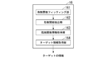
- the signal processing unit 16 includes an exponential function fitting unit 161, an exponential function extraction unit 162, an exponential function information acquisition unit 163, and a target information acquisition unit 164.
- the exponential function fitting unit 161 is an exponential function having a real part and an imaginary part with the input signal as an argument, and fits by the Prony method.
- the Prony method is a method of fitting a data series with an exponential function.
- the exponential function extraction unit 162 extracts an exponential function whose absolute value of the real part is equal to or less than a predetermined value among the exponential functions obtained by fitting.
- the exponential function information acquisition unit 163 acquires the amplitude value and the value of the imaginary part from the extracted exponential function.
- the target information acquisition unit 164 acquires the value of the relative amplitude of the target and the value of the distance from the acquired exponential function information.
- ⁇ Distance measurement method> an example of the distance measurement method will be described.
- a pulsed radio wave modulated so that the frequency of the transmitted radio wave changes linearly with time is transmitted toward the target.
- the transmitted radio wave signal e T (t) is expressed as follows.
- Equation (1) j is an imaginary unit, t is time, f 0 is the carrier frequency, c is the speed of light, ⁇ f is the frequency change width, and TC is the pulse time width.
- j is an imaginary unit
- t time
- f 0 is the carrier frequency
- c is the speed of light
- ⁇ f is the frequency change width
- TC is the pulse time width.
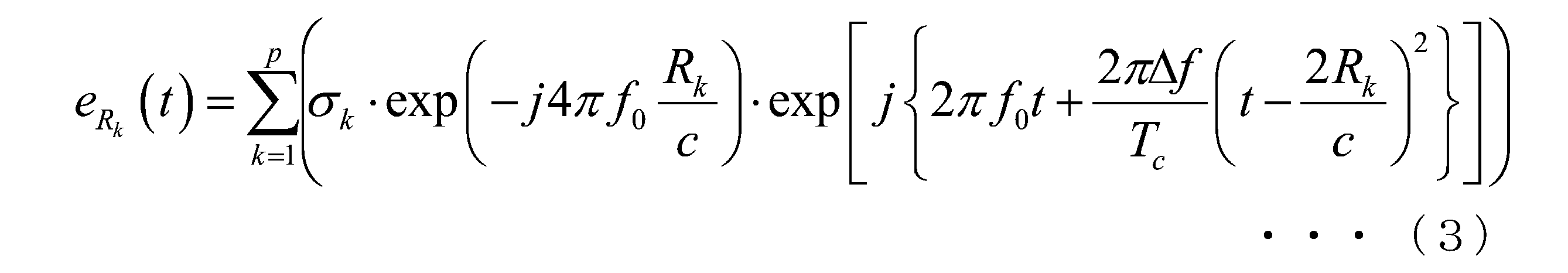
- Equation (2) ⁇ k is the scattering coefficient of the target. Further, the equation (2) is an echo signal when one target exists. Generalizing this, the echo signal eRk (t) when p targets exist is given by the following equation (3).
- the inverse correlation processing of the echo signal and the transmission signal is performed on the signal obtained by converting these signals into a baseband.
- the equation obtained by converting the transmission signal e T (t) into the baseband signal b T (t) is the following equation (4).
- the echo signal b Rk (t) is a signal obtained by shifting the time of the baseband signal b T (t) by 2 R k / c and multiplying by a coefficient. Therefore, assuming that the spectral signal of the baseband signal b T (t) is BT ( ⁇ ), the spectral signal BR k ( ⁇ ) of b Rk ( t ) uses BT ( ⁇ ) and is given by the following equation (6). ).
- the inverse correlation process is performed by dividing BRk ( ⁇ ) by BT ( ⁇ ) in the spectral region.
- the signal obtained by dividing BRk ( ⁇ ) by BT ( ⁇ ) is expressed by the following equation (7).
- the signal obtained by the inverse correlation processing in the spectral region is the sum of the exponential functions.
- the signal actually obtained is a data series composed of numerical values.
- the Prony method is known as a method of fitting a data series to an exponential function. Therefore, in the present embodiment, the amplitude of the exponential function ⁇ k ⁇ exp ( ⁇ j4 ⁇ f 0 R k / c) is obtained by fitting the data series obtained by performing the inverse correlation processing in the spectral region to the exponential function by the Prony method. And the argument (-j2R k ) / c. Thereby, in the present embodiment, the distance Rk of the target can be obtained.
- Equation (7) is an ideal equation, but since the signal actually obtained contains noise, when it is fitted by the Prony method, BRk ( ⁇ ) is divided by BT ( ⁇ ). As the signal ⁇ ⁇ , a signal expressed by the following equation (8) can be obtained.
- ⁇ k is obtained in addition to ⁇ k ⁇ exp ( ⁇ j4 ⁇ f 0 R k / c) and ( ⁇ j2 R k ) / c.
- equation (7) since ⁇ k for the target is 0 in the ideal state, when a signal containing noise is fitted by the Prony method, ⁇ k for the target is small even if it is not 0. Considered to be a value.
- ⁇ k for noise is not always a small value, but is considered to be an arbitrary value.
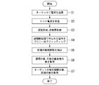
- FIG. 3 is a flowchart of the distance measurement processing procedure according to the present embodiment.
- Step S1 The antenna 14 radiates the radio wave input from the circulator unit 13 toward the target.
- Step S2 The antenna 14 receives the echo radio wave scattered by the target and returned.
- Step S3 The delay circuit 12 delays the pulse radio wave input from the oscillating unit 11 by an integral multiple including 0 times the pulse time. Subsequently, the inverse correlation unit 15 performs an inverse correlation in the frequency domain with the pulse radio wave input from the delay circuit 12 and the radio wave input from the circulator unit 13.
- Step S4 The exponential function fitting unit 161 fits the signal obtained by the inverse correlation processing by the Prony method.
- Step S5 The exponential function extraction unit 162 extracts an exponential function whose absolute value of the real part of the argument is equal to or less than a predetermined value among the exponential functions obtained by fitting.
- Step S6 The exponential function information acquisition unit 163 acquires the amplitude value and the imaginary part value of the argument from the extracted exponential function.
- Step S7 The target information acquisition unit 164 acquires the value of the relative amplitude of the target and the value of the distance from the acquired exponential function information.
- the object transmitted and received by the distance measuring device is not limited to radio waves, but may be light, sound waves, or the like.
- the method of the present embodiment can be applied to a device that performs pulse compression even if the device transmits and receives using light or sound waves. That is, the "frequency-modulated pulse wave" is due to radio waves, light, sound waves, and the like.
- the simulation condition is that the carrier frequency is 76 [GHz], and the radio wave modulated so that the frequency increases linearly by 500 [MHz] in 1 [ ⁇ sec] is transmitted from the pulse compression radar. Then, in the simulation, the echo radio waves that are scattered from two targets with the same radar scattering cross section existing at the distances of 20.0 [m] and 20.2 [m] from the radar and return to the radar are signal pairs. The target information obtained when the noise ratio was acquired in an environment of 20 [dB] was examined.
- FIG. 4 is a diagram showing information of the top 5 relative amplitudes among the target information obtained by the simulation.
- FIG. 5 shows the results of illustrating the target information with a distance of 10 to 30 [m] among the target information obtained by the simulation.
- FIG. 5 is a diagram showing the relationship between the distance and the relative strength obtained by the simulation in the present embodiment.
- the horizontal axis is the distance [m] and the vertical axis is the relative intensity [dB].
- the relative amplitude differs by 20 [dB] or more between the upper 2 and the upper 3 or less, so that the upper 2 is the target information and the upper 3 or less is the information due to noise. .. Therefore, it can be seen that there are two targets.
- the distance between the two target information has a very small error of 4 [cm] and 9 [cm] from the actual distance.
- the difference between the relative amplitudes of the two targets is as small as 0.48 [dB].
- the accuracy and resolution of the distance measurement obtained by the conventional method is 30 [cm].
- the accuracy and resolution of the distance measurement obtained by the conventional method is 30 [cm].
- the present embodiment it is possible to identify two targets approaching 30 [cm] or less as shown in FIGS. 4 and 5. Further, the error in the distance between the two obtained targets is 9 [cm] at the maximum, which is less than one-third of the distance measurement accuracy of the conventional method. From these, according to the present embodiment, the number of targets, the distance, and the relative amplitude can be obtained without being limited to the value determined from the frequency change width of the pulse compression radar system.
- FIG. 6 is a diagram showing the results of simulation performed by a conventional method.
- the horizontal axis is the distance [m] and the vertical axis is the relative intensity [dB].
- the simulation conditions are the same as the numerical simulation performed to confirm the effect of the method of this embodiment.
- the target exists in the vicinity of 20.0 [m], and it is not possible to recognize that there are two targets.
- the echo radio wave and the transmitted radio wave are fitted by the prony method with an exponential function having a real part and an imaginary part with a signal obtained by inversely correlating in the frequency region as an argument, and obtained by fitting.
- the amplitude value and the imaginary part value of the argument are acquired from the extracted exponential function, and the relative amplitude value of the target and the distance value are acquired from the acquired exponential function information. I made it.
- the measurement accuracy and the resolution can be improved from the values determined by the frequency change width of the transmitted radio wave.
- a program for realizing all or part of the functions of the distance measuring device 1 in the present invention is recorded on a computer-readable recording medium, and the program recorded on the recording medium is read into a computer system and executed. By doing so, all or part of the processing performed by the distance measuring device 1 may be performed.
- the term "computer system” as used herein includes hardware such as an OS and peripheral devices. Further, the “computer system” shall also include a WWW system provided with a homepage providing environment (or display environment). Further, the "computer-readable recording medium” refers to a portable medium such as a flexible disk, a magneto-optical disk, a ROM, or a CD-ROM, and a storage device such as a hard disk built in a computer system.
- a "computer-readable recording medium” is a volatile memory (RAM) inside a computer system that serves as a server or client when a program is transmitted via a network such as the Internet or a communication line such as a telephone line.
- RAM volatile memory
- the above program may be transmitted from a computer system in which this program is stored in a storage device or the like to another computer system via a transmission medium or by a transmission wave in the transmission medium.
- the "transmission medium” for transmitting a program refers to a medium having a function of transmitting information, such as a network (communication network) such as the Internet or a communication line (communication line) such as a telephone line.
- the above program may be for realizing a part of the above-mentioned functions.
- a so-called difference file (difference program) may be used, which can realize the above-mentioned function in combination with a program already recorded in the computer system.
Landscapes
- Engineering & Computer Science (AREA)
- Radar, Positioning & Navigation (AREA)
- Remote Sensing (AREA)
- Computer Networks & Wireless Communication (AREA)
- Physics & Mathematics (AREA)
- General Physics & Mathematics (AREA)
- Radar Systems Or Details Thereof (AREA)
Abstract
This distance measuring device is provided with a signal processing unit which transmits a frequency modulated pulse wave toward a target, and which employs Prony's method, using an exponential function having an argument with a real part and an imaginary part, to fit a signal obtained by inverse correlation, in the frequency domain, of an echo wave that has been reflected by the target and has returned with the transmitted pulse wave.
Description
本発明は、距離計測装置、距離計測方法、及びプログラムに関する。
本願は、2020年11月 9日に、日本に出願された特願2020-186767号に基づき優先権を主張し、その内容をここに援用する。 The present invention relates to a distance measuring device, a distance measuring method, and a program.
This application claims priority based on Japanese Patent Application No. 2020-186767 filed in Japan on November 9, 2020, the contents of which are incorporated herein by reference.
パルス圧縮レーダは、周波数が時間に対して直線的に変化するように変調させたパルス電波をターゲットに向けて送信する。パルス圧縮レーダは、ターゲットで反射されてレーダに戻って来たエコー電波をパルス時間幅毎に送信したパルス電波と逆相関処理を行うと、レーダとターゲットの距離の2倍に対応した時刻がピークとなる信号が得られる。パルス圧縮レーダは、ピークとなる時刻を検出すると、ターゲットの距離を計測することができる。以上がパルス圧縮レーダでの距離計測の原理である。この時、周波数変化幅をΔfとすると、距離分解能Δdは、{c/(2Δf)}で与えられる。ここでcは光速である(例えば非特許文献1参照)。なお、パルス圧縮レーダの距離分解能は、非特許文献1の式(1.14)Rres=cτ/2のパルス幅τに、パルス圧縮後の波形のパルス幅の1/Δfを代入すれば求めることができる。
The pulse compression radar transmits a pulsed radio wave modulated so that the frequency changes linearly with time toward the target. When the pulse compression radar performs inverse correlation processing with the pulse radio waves that transmit the echo radio waves reflected by the target and returned to the radar for each pulse time width, the time corresponding to twice the distance between the radar and the target peaks. Is obtained. The pulse compression radar can measure the distance of the target when it detects the peak time. The above is the principle of distance measurement with a pulse compression radar. At this time, assuming that the frequency change width is Δf, the distance resolution Δd is given by {c / (2Δf)}. Here, c is the speed of light (see, for example, Non-Patent Document 1). The distance resolution of the pulse compression radar can be obtained by substituting 1 / Δf of the pulse width of the waveform after pulse compression into the pulse width τ of the equation (1.14) R res = cτ / 2 of Non-Patent Document 1. be able to.
しかしながら、従来技術では、ターゲットの距離が、非特許文献1も記載のように距離分解能単位での計測となる。このため、従来技術では、距離計測精度、分解能がパルス圧縮レーダの周波数変化幅から定まる値に制限されるという課題があった。
However, in the prior art, the distance of the target is measured in the distance resolution unit as described in Non-Patent Document 1. Therefore, in the prior art, there is a problem that the distance measurement accuracy and the resolution are limited to the values determined by the frequency change width of the pulse compression radar.
本発明は、上記の問題点に鑑みてなされたものであって、計測精度、分解能を送信電波の周波数変化幅から決まる値より向上できる距離計測装置、距離計測方法、及びプログラムを提供することを目的とする。
The present invention has been made in view of the above problems, and provides a distance measuring device, a distance measuring method, and a program capable of improving the measurement accuracy and the resolution from the values determined by the frequency change width of the transmitted radio wave. The purpose.
上記目的を達成するため、本発明の一態様に係る距離計測装置は、周波数変調したパルス波をターゲットに向けて送信し、前記ターゲットで反射されて戻って来たエコー波を送信した前記パルス波と周波数領域で逆相関して得られる信号を、引数に実数部と虚数部とを有する指数関数でプロニー法によりフィッティングする信号処理部、を備える。
In order to achieve the above object, the distance measuring device according to one aspect of the present invention transmits a frequency-modulated pulse wave toward a target, and transmits the echo wave reflected and returned by the target. It is provided with a signal processing unit for fitting a signal obtained by inversely correlating with and in the frequency domain by a prony method using an exponential function having a real part and an imaginary part as arguments.
また、本発明の一態様に係る距離計測装置において、前記信号処理部は、前記フィッティングにより得られた指数関数のうち、前記実数部の絶対値が所定値以下の指数関数を抽出するようにしてもよい。
Further, in the distance measuring device according to one aspect of the present invention, the signal processing unit extracts an exponential function in which the absolute value of the real part is equal to or less than a predetermined value from the exponential functions obtained by the fitting. May be good.
また、本発明の一態様に係る距離計測装置において、前記信号処理部は、前記抽出した指数関数から振幅の値、及び前記虚数部の値を取得するようにしてもよい。
Further, in the distance measuring device according to one aspect of the present invention, the signal processing unit may acquire the value of the amplitude and the value of the imaginary part from the extracted exponential function.
また、本発明の一態様に係る距離計測装置において、前記信号処理部は、前記取得した振幅の値、及び前記虚数部の値を含む指数関数情報から、前記ターゲットの相対振幅の値、及び距離の値を取得するようにしてもよい。
Further, in the distance measuring device according to one aspect of the present invention, the signal processing unit has the relative amplitude value of the target and the distance from the exponential function information including the acquired amplitude value and the imaginary number part value. You may try to get the value of.
また、本発明の一態様に係る距離計測装置において、前記取得した相対振幅の値、及び距離の値を含むターゲット情報を表示する表示部を更に備えるようにしてもよい。
Further, the distance measuring device according to one aspect of the present invention may further include a display unit for displaying target information including the acquired relative amplitude value and the distance value.
上記目的を達成するため、本発明の一態様に係る距離計測方法は、コンピュータが、周波数変調したパルス波をターゲットに向けて送信し、前記ターゲットで反射されて戻って来たエコー波を送信した前記パルス波と周波数領域で逆相関して得られる信号を、引数に実数部と虚数部とを有する指数関数でプロニー法によりフィッティングする。
In order to achieve the above object, in the distance measuring method according to one aspect of the present invention, a computer transmits a frequency-modulated pulse wave toward a target, and transmits an echo wave reflected by the target and returned. A signal obtained by inversely correlating with the pulse wave in the frequency domain is fitted by the Prony method with an exponential function having a real part and an imaginary part as arguments.
上記目的を達成するため、本発明の一態様に係るプログラムは、コンピュータに、周波数変調したパルス波をターゲットに向けて送信させ、前記ターゲットで反射されて戻って来たエコー波を送信した前記パルス波と周波数領域で逆相関して得られる信号を、引数に実数部と虚数部とを有する指数関数でプロニー法によりフィッティングさせる。
In order to achieve the above object, the program according to one aspect of the present invention causes a computer to transmit a frequency-modulated pulse wave toward a target, and transmits the echo wave reflected and returned by the target. A signal obtained by inversely correlating with a wave in the frequency domain is fitted by the Prony method with an exponential function having a real part and an imaginary part as arguments.
本発明によれば、計測精度、分解能を送信電波の周波数変化幅から決まる値より向上できる。
According to the present invention, the measurement accuracy and resolution can be improved from the values determined by the frequency change width of the transmitted radio wave.
以下、本発明の実施の形態について図面を参照しながら説明する。なお、以下の例では、距離計測装置をレーダ装置に適用する例を説明する。
Hereinafter, embodiments of the present invention will be described with reference to the drawings. In the following example, an example of applying the distance measuring device to the radar device will be described.
<距離計測装置の構成例>
図1は、本実施形態に係る距離計測装置の構成例を示すブロック図である。図1のように、距離計測装置1は、発振部11、遅延回路12、サーキュレータ部13、アンテナ14、逆相関部15、信号処理部16、および表示部17を備える。 <Configuration example of distance measuring device>
FIG. 1 is a block diagram showing a configuration example of a distance measuring device according to the present embodiment. As shown in FIG. 1, thedistance measuring device 1 includes an oscillation unit 11, a delay circuit 12, a circulator unit 13, an antenna 14, an inverse correlation unit 15, a signal processing unit 16, and a display unit 17.
図1は、本実施形態に係る距離計測装置の構成例を示すブロック図である。図1のように、距離計測装置1は、発振部11、遅延回路12、サーキュレータ部13、アンテナ14、逆相関部15、信号処理部16、および表示部17を備える。 <Configuration example of distance measuring device>
FIG. 1 is a block diagram showing a configuration example of a distance measuring device according to the present embodiment. As shown in FIG. 1, the
距離計測装置1は、例えばパルス圧縮レーダ装置であり、ターゲットに向けてパルス電波(「パルス波」ともいう)を送信し、ターゲットで反射されてレーダに戻って来たエコー電波(「エコー波」ともいう)を送信したパルス電波と周波数領域で逆相関して得られる信号を処理することにより、ターゲットの距離を計測する。
The distance measuring device 1 is, for example, a pulse compression radar device, and is an echo radio wave (“echo wave”) that transmits a pulse radio wave (also referred to as “pulse wave”) toward a target, is reflected by the target, and returns to the radar. The distance of the target is measured by processing the signal obtained by inversely correlating with the pulsed radio wave transmitted (also referred to as) in the frequency region.
発振部11は、周波数が時間に対して直線的に変化するように変調させたパルス電波を、遅延回路12とサーキュレータ部13へ出力する。
The oscillation unit 11 outputs a pulsed radio wave modulated so that the frequency changes linearly with time to the delay circuit 12 and the circulator unit 13.
遅延回路12は、発振部11から入力されたパルス電波をパルス時間の0倍を含む整数倍の時間を遅らせ、逆相関部15へ出力する。
The delay circuit 12 delays the pulse radio wave input from the oscillation unit 11 by an integral multiple including 0 times the pulse time, and outputs the pulse radio wave to the inverse correlation unit 15.
サーキュレータ部13は、発振部11から入力された電波をアンテナ14へ出力する。また、サーキュレータ部13は、アンテナ14から入力された電波を逆相関部15へ出力する。
The circulator unit 13 outputs the radio wave input from the oscillation unit 11 to the antenna 14. Further, the circulator unit 13 outputs the radio wave input from the antenna 14 to the inverse correlation unit 15.
アンテナ14は、サーキュレータ部13から入力された電波をターゲットへ向けて放射するとともに、ターゲットで散乱されて戻ってきたエコー電波を受信し、サーキュレータ部13へ出力する。アンテナ14は、例えば、ダイポール系のアンテナ、ホーンアンテナ、パラボラアンテナ、アレイアンテナなど如何なるアンテナでも用いることができる。
The antenna 14 radiates the radio wave input from the circulator unit 13 toward the target, receives the echo radio wave scattered by the target and returns, and outputs the echo wave to the circulator unit 13. The antenna 14 can be any antenna such as a dipole antenna, a horn antenna, a parabolic antenna, and an array antenna.
逆相関部15は、遅延回路12から入力されたパルス電波とサーキュレータ部13から入力された電波を周波数領域で逆相関して得られる信号を信号処理部16へ出力する。
The inverse correlation unit 15 outputs a signal obtained by inversely correlating the pulse radio wave input from the delay circuit 12 and the radio wave input from the circulator unit 13 in the frequency domain to the signal processing unit 16.
信号処理部16は、所定の信号処理を施し、ターゲットの相対振幅の値、及び距離の値を表示部17へ出力する。
The signal processing unit 16 performs predetermined signal processing and outputs the value of the relative amplitude of the target and the value of the distance to the display unit 17.
表示部17は、例えば液晶表示装置や有機EL(Electro Luminescence)表示装置等であり、信号処理部16からの出力に基づきターゲットの相対強度及び距離に関する情報を表示する。
The display unit 17 is, for example, a liquid crystal display device, an organic EL (Electroluminescence) display device, or the like, and displays information on the relative strength and distance of the target based on the output from the signal processing unit 16.
<信号処理部16の構成例>
次に、信号処理部16の構成例を説明する。図2は、本実施形態に係る信号処理部の構成例を示すブロック図である。図2のように、信号処理部16は、指数関数フィッティング部161、指数関数抽出部162、指数関数情報取得部163、およびターゲット情報取得部164を備える。 <Configuration example ofsignal processing unit 16>
Next, a configuration example of thesignal processing unit 16 will be described. FIG. 2 is a block diagram showing a configuration example of the signal processing unit according to the present embodiment. As shown in FIG. 2, the signal processing unit 16 includes an exponential function fitting unit 161, an exponential function extraction unit 162, an exponential function information acquisition unit 163, and a target information acquisition unit 164.
次に、信号処理部16の構成例を説明する。図2は、本実施形態に係る信号処理部の構成例を示すブロック図である。図2のように、信号処理部16は、指数関数フィッティング部161、指数関数抽出部162、指数関数情報取得部163、およびターゲット情報取得部164を備える。 <Configuration example of
Next, a configuration example of the
指数関数フィッティング部161は、入力された信号を引数に実数部と虚数部とを有する指数関数でプロニー(Prony)法によりフィッティングする。なお、プロニー法は、データ系列を指数関数でフィッティングする手法である。
The exponential function fitting unit 161 is an exponential function having a real part and an imaginary part with the input signal as an argument, and fits by the Prony method. The Prony method is a method of fitting a data series with an exponential function.
指数関数抽出部162は、フィッティングにより得られた指数関数のうち、前記実数部の絶対値が所定値以下の指数関数を抽出する。
The exponential function extraction unit 162 extracts an exponential function whose absolute value of the real part is equal to or less than a predetermined value among the exponential functions obtained by fitting.
指数関数情報取得部163は、抽出した指数関数から振幅の値、前記虚数部の値を取得する。
The exponential function information acquisition unit 163 acquires the amplitude value and the value of the imaginary part from the extracted exponential function.
ターゲット情報取得部164は、取得した指数関数情報から、ターゲットの相対振幅の値、及び距離の値を取得する。
The target information acquisition unit 164 acquires the value of the relative amplitude of the target and the value of the distance from the acquired exponential function information.
<距離測定の方法>
次に、距離測定方法例を説明する。
パルス圧縮レーダでは、送信した電波の周波数が時間に対して直線的に変化するように変調させたパルス電波をターゲットに向けて送信する。送信電波信号eT(t)は以下で表現される。 <Distance measurement method>
Next, an example of the distance measurement method will be described.
In the pulse compression radar, a pulsed radio wave modulated so that the frequency of the transmitted radio wave changes linearly with time is transmitted toward the target. The transmitted radio wave signal e T (t) is expressed as follows.

式(1)において、jは虚数単位、tは時間、f0はキャリア周波数、cは光速であり、Δfは周波数変化幅であり、TCはパルス時間幅である。ここでは説明を簡略化するために、ターゲットはレーダからcTC/2の距離内に存在する場合を考える。
レーダからターゲットまでの距離をRkとすると、ターゲットのエコー信号は、2Rk/cの時間後にレーダに到達するので、エコー信号eRk(t)は、次式(2)で表現される。 In equation (1), j is an imaginary unit, t is time, f 0 is the carrier frequency, c is the speed of light, Δf is the frequency change width, and TC is the pulse time width. Here, for the sake of brevity, consider the case where the target is within a distance of cTC / 2 from the radar.
Assuming that the distance from the radar to the target is R k , the echo signal of the target reaches the radar after a time of 2 R k / c, so that the echo signal e Rk (t) is expressed by the following equation (2).
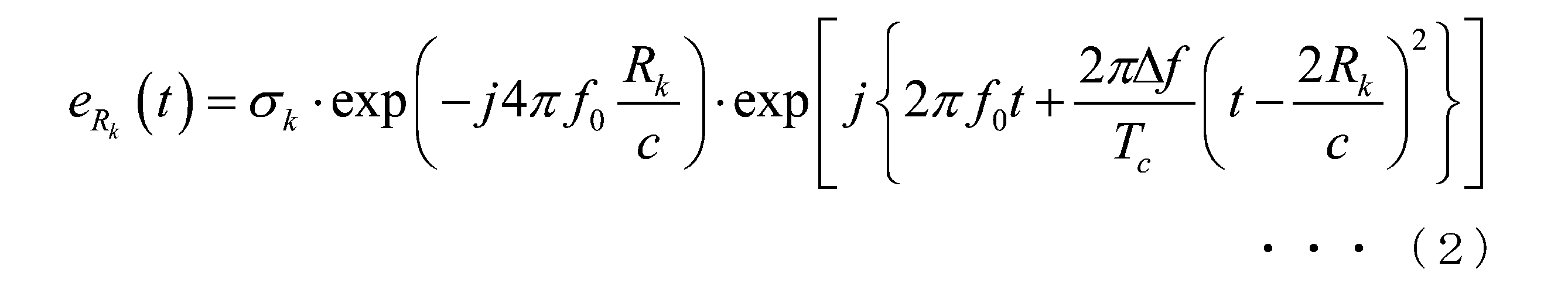
式(2)において、σkはターゲットの散乱係数である。また、式(2)はターゲットが1個存在している場合のエコー信号である。これを一般化し、p個のターゲットが存在している場合のエコー信号eRk(t)は、次式(3)となる。
In equation (2), σ k is the scattering coefficient of the target. Further, the equation (2) is an echo signal when one target exists. Generalizing this, the echo signal eRk (t) when p targets exist is given by the following equation (3).
エコー信号と送信信号の逆相関処理は、これらの信号をベースバンドに変換した信号で実施する。送信信号eT(t)をベースバンド信号bT(t)に変換した式は、次式(4)となる。
The inverse correlation processing of the echo signal and the transmission signal is performed on the signal obtained by converting these signals into a baseband. The equation obtained by converting the transmission signal e T (t) into the baseband signal b T (t) is the following equation (4).

エコー信号eRk(t)をベースバンド信号bRT(t)に変換した式は、次式(5)となる。
The equation obtained by converting the echo signal e Rk (t) into the baseband signal b RT (t) is the following equation (5).

逆相関処理はスペクトル領域では除算となるため、効率的に実施できる。エコー信号bRk(t)は、ベースバンド信号bT(t)の時間を2Rk/cずらし、係数を乗じた信号である。このため、ベースバンド信号bT(t)のスペクトル信号をBT(ω)とすると、bRk(t)のスペクトル信号BRk(ω)はBT(ω)を使用して次式(6)で表現される。
Since the inverse correlation processing is division in the spectral region, it can be efficiently performed. The echo signal b Rk (t) is a signal obtained by shifting the time of the baseband signal b T (t) by 2 R k / c and multiplying by a coefficient. Therefore, assuming that the spectral signal of the baseband signal b T (t) is BT (ω), the spectral signal BR k (ω) of b Rk ( t ) uses BT (ω) and is given by the following equation (6). ).

逆相関処理は、スペクトル領域でBRk(ω)をBT(ω)で割ることで実施される。BRk(ω)をBT(ω)で割った信号は、次式(7)で表現される。
The inverse correlation process is performed by dividing BRk (ω) by BT (ω) in the spectral region. The signal obtained by dividing BRk (ω) by BT (ω) is expressed by the following equation (7).

この信号をフーリエ変換で時間領域に再変換すると逆相関処理が完了する。これが従来の逆相関処理である。
When this signal is reconverted into the time domain by Fourier transform, the inverse correlation process is completed. This is the conventional inverse correlation process.
式(7)から分かるように、スペクトル領域で逆相関処理をして得られる信号は、指数関数の和となる。実際に得られる信号は数値で構成されるデータ系列である。データ系列を指数関数にフィッティングする方法としてプロニー法が知られている。このため、本実施形態では、スペクトル領域で逆相関処理をして得られるデータ系列をプロニー法で指数関数にフィッティングすることで、指数関数の振幅σk・exp(-j4πf0Rk/c)と引数(-j2Rk)/cを求める。これにより、本実施形態では、ターゲットの距離Rkを求めることができる。
As can be seen from the equation (7), the signal obtained by the inverse correlation processing in the spectral region is the sum of the exponential functions. The signal actually obtained is a data series composed of numerical values. The Prony method is known as a method of fitting a data series to an exponential function. Therefore, in the present embodiment, the amplitude of the exponential function σ k · exp (−j4πf 0 R k / c) is obtained by fitting the data series obtained by performing the inverse correlation processing in the spectral region to the exponential function by the Prony method. And the argument (-j2R k ) / c. Thereby, in the present embodiment, the distance Rk of the target can be obtained.
この方法では、従来の方法のように帯域Δfの制約を受けることなく、ターゲットの距離Rkを数値で直接求めるため、精確に求めることができる。
式(7)は理想的な場合の式であるが、実際に得られる信号にはノイズが含まれるため、それをプロニー法でフィッティングすると、BRk(ω)をBT(ω)で割った信号{・^}は、次式(8)で表現される信号が得られる。 In this method, the distance R k of the target is directly obtained numerically without being restricted by the band Δf as in the conventional method, so that the distance R k can be obtained accurately.
Equation (7) is an ideal equation, but since the signal actually obtained contains noise, when it is fitted by the Prony method, BRk (ω) is divided by BT (ω). As the signal {・ ^}, a signal expressed by the following equation (8) can be obtained.
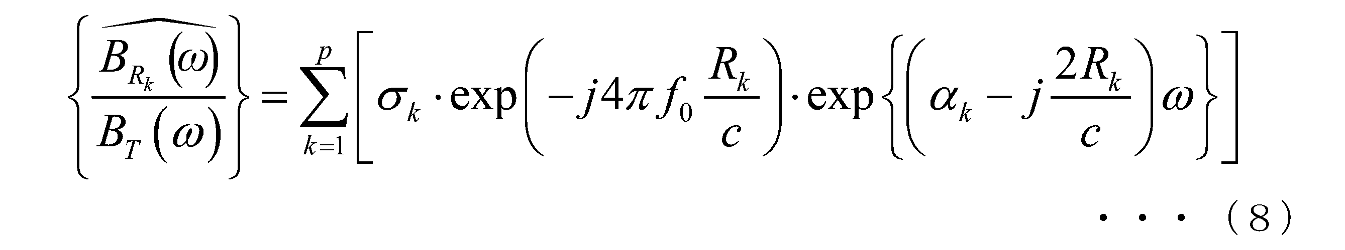
実際の信号をプロニー法でフィッティングすると、αk・exp(-j4πf0Rk/c)と(-j2Rk)/cの他にαkも求められる。式(7)に示したように、理想的な状態ではターゲットに対するαkは0であるので、ノイズが含まれる信号をプロニー法でフィッティングした場合、ターゲットに対するαkは0ではないとしても、小さい値であると考えられる。
When the actual signal is fitted by the Prony method, α k is obtained in addition to α k · exp (−j4πf 0 R k / c) and (−j2 R k ) / c. As shown in equation (7), since α k for the target is 0 in the ideal state, when a signal containing noise is fitted by the Prony method, α k for the target is small even if it is not 0. Considered to be a value.
ノイズに対するαkは、小さい値であるとは限らず、任意の値であると考えられる。αkの大きさのこの違いを利用すると、得られた指数関数の中から、ノイズに対する指数関数の一部を取り除くことで、ターゲットに対する指数関数を効率よく抽出することが可能となる。
Α k for noise is not always a small value, but is considered to be an arbitrary value. By utilizing this difference in the magnitude of α k , it is possible to efficiently extract the exponential function for the target by removing a part of the exponential function for noise from the obtained exponential function.
<距離計測方法>
次に、距離測定の処理手順例を説明する。図3は、本実施形態に係る距離測定の処理手順のフローチャートである。 <Distance measurement method>
Next, an example of the processing procedure for distance measurement will be described. FIG. 3 is a flowchart of the distance measurement processing procedure according to the present embodiment.
次に、距離測定の処理手順例を説明する。図3は、本実施形態に係る距離測定の処理手順のフローチャートである。 <Distance measurement method>
Next, an example of the processing procedure for distance measurement will be described. FIG. 3 is a flowchart of the distance measurement processing procedure according to the present embodiment.
(ステップS1)アンテナ14は、サーキュレータ部13から入力された電波をターゲットへ向けて放射する。
(Step S1) The antenna 14 radiates the radio wave input from the circulator unit 13 toward the target.
(ステップS2)アンテナ14は、ターゲットで散乱されて戻ってきたエコー電波を受信する。
(Step S2) The antenna 14 receives the echo radio wave scattered by the target and returned.
(ステップS3)遅延回路12は、発振部11から入力されたパルス電波をパルス時間の0倍を含む整数倍の時間を遅らせる。続けて、逆相関部15は、遅延回路12から入力されたパルス電波とサーキュレータ部13から入力された電波に対して周波数領域で逆相関を行う。
(Step S3) The delay circuit 12 delays the pulse radio wave input from the oscillating unit 11 by an integral multiple including 0 times the pulse time. Subsequently, the inverse correlation unit 15 performs an inverse correlation in the frequency domain with the pulse radio wave input from the delay circuit 12 and the radio wave input from the circulator unit 13.
(ステップS4)指数関数フィッティング部161は、逆相関処理で得られる信号をプロニー法によりフィッティングする。
(Step S4) The exponential function fitting unit 161 fits the signal obtained by the inverse correlation processing by the Prony method.
(ステップS5)指数関数抽出部162は、フィッティングにより得られた指数関数のうち、引数の実数部の絶対値が所定値以下の指数関数を抽出する。
(Step S5) The exponential function extraction unit 162 extracts an exponential function whose absolute value of the real part of the argument is equal to or less than a predetermined value among the exponential functions obtained by fitting.
(ステップS6)指数関数情報取得部163は、抽出された指数関数から振幅の値、引数の虚数部の値を取得する。
(Step S6) The exponential function information acquisition unit 163 acquires the amplitude value and the imaginary part value of the argument from the extracted exponential function.
(ステップS7)ターゲット情報取得部164は、取得された指数関数情報から、ターゲットの相対振幅の値、及び距離の値を取得する。
(Step S7) The target information acquisition unit 164 acquires the value of the relative amplitude of the target and the value of the distance from the acquired exponential function information.
なお、上述した例では電波を送受信する例を説明したが、これに限らない。距離計測装置が送受信する対象は電波に限らず、光、音波等であってもよい。このように、光や音波を用いて送受信する装置であっても、パルス圧縮を行う装置に、本実施形態の手法を適用することができる。すなわち、「周波数変調したパルス波」は、電波、光および音波等によるものである。
In the above example, an example of transmitting and receiving radio waves was explained, but the present invention is not limited to this. The object transmitted and received by the distance measuring device is not limited to radio waves, but may be light, sound waves, or the like. As described above, the method of the present embodiment can be applied to a device that performs pulse compression even if the device transmits and receives using light or sound waves. That is, the "frequency-modulated pulse wave" is due to radio waves, light, sound waves, and the like.
<評価>
次に、本実施形態の手法の効果を確認するために行った数値シミュレーション結果例を説明する。
シミュレーション条件は、キャリア周波数が76[GHz]で、1[μ秒]の間に周波数が直線的に500[MHz]増加するように変調させた電波をパルス圧縮レーダから送信する。そして、シミュレーションでは、レーダから20.0[m]と20.2[m]の距離に存在しているレーダ散乱断面積が等しい2つのターゲットから散乱され、レーダに戻ってくるエコー電波を信号対雑音比が20[dB]の環境で取得した際に得られるターゲット情報を検討した。 <Evaluation>
Next, an example of numerical simulation results performed to confirm the effect of the method of this embodiment will be described.
The simulation condition is that the carrier frequency is 76 [GHz], and the radio wave modulated so that the frequency increases linearly by 500 [MHz] in 1 [μsec] is transmitted from the pulse compression radar. Then, in the simulation, the echo radio waves that are scattered from two targets with the same radar scattering cross section existing at the distances of 20.0 [m] and 20.2 [m] from the radar and return to the radar are signal pairs. The target information obtained when the noise ratio was acquired in an environment of 20 [dB] was examined.
中間周波数信号を引数に実数部と虚数部とを有する指数関数でプロニー法によりフィッティングして得られた指数関数の内、引数の実数部の絶対値が0.003以下となる指数関数を抽出し、指数関数の振幅値からターゲットの相対振幅を取得し、指数関数の引数の虚数部からターゲットの距離を取得した結果を図4に示す。図4は、シミュレーションによって得られたターゲット情報の内、相対振幅が上位5までの情報を示した図である。
From the exponential functions obtained by fitting by the Prony method with an exponential function having a real part and an imaginary part with an intermediate frequency signal as an argument, an exponential function in which the absolute value of the real part of the argument is 0.003 or less is extracted. , The relative amplitude of the target is obtained from the amplitude value of the exponential function, and the distance of the target is obtained from the imaginary part of the argument of the exponential function. The result is shown in FIG. FIG. 4 is a diagram showing information of the top 5 relative amplitudes among the target information obtained by the simulation.
シミュレーションで得られたターゲット情報の内、距離が10~30[m]までのターゲット情報を図示した結果を図5に示す。図5は、本実施形態におけるシミュレーションによって得られた距離と相対強度の関係を示す図である。図5において、横軸は距離[m]であり、縦軸は相対強度[dB]である。
FIG. 5 shows the results of illustrating the target information with a distance of 10 to 30 [m] among the target information obtained by the simulation. FIG. 5 is a diagram showing the relationship between the distance and the relative strength obtained by the simulation in the present embodiment. In FIG. 5, the horizontal axis is the distance [m] and the vertical axis is the relative intensity [dB].
図4より、相対振幅が上位2までと上位3以下とでは、相対振幅が20[dB]以上異なることより、上位2までがターゲットの情報で、上位3以下は雑音による情報であることが分かる。従って、ターゲットは2つ存在していることが分かる。2つのターゲット情報の内の距離は、実際の距離との誤差が4[cm]、9[cm]と非常に小さい。また、2つのターゲットの相対振幅の差は0.48[dB]と非常に小さい。
From FIG. 4, it can be seen that the relative amplitude differs by 20 [dB] or more between the upper 2 and the upper 3 or less, so that the upper 2 is the target information and the upper 3 or less is the information due to noise. .. Therefore, it can be seen that there are two targets. The distance between the two target information has a very small error of 4 [cm] and 9 [cm] from the actual distance. Moreover, the difference between the relative amplitudes of the two targets is as small as 0.48 [dB].
シミュレーションで使用した周波数変化幅は500[MHz]であるので、従来の手法で得られる距離計測の精度、分解能は30[cm]である。これに対して、本実施形態によれば、図4、図5のように30[cm]以下に接近している2つのターゲットを識別することができている。また、得られた2つのターゲットの距離の誤差は最大で9[cm]であり、従来の手法の距離計測精度の3分の1未満である。これらより、本実施形態により、パルス圧縮レーダシステムの周波数変化幅から定まる値に制限されることなく、ターゲットの数、距離、及び相対振幅を求められる。
Since the frequency change width used in the simulation is 500 [MHz], the accuracy and resolution of the distance measurement obtained by the conventional method is 30 [cm]. On the other hand, according to the present embodiment, it is possible to identify two targets approaching 30 [cm] or less as shown in FIGS. 4 and 5. Further, the error in the distance between the two obtained targets is 9 [cm] at the maximum, which is less than one-third of the distance measurement accuracy of the conventional method. From these, according to the present embodiment, the number of targets, the distance, and the relative amplitude can be obtained without being limited to the value determined from the frequency change width of the pulse compression radar system.
ここで、比較例を説明する。図6は、従来の手法によりシミュレーションを行った結果を示す図である。図6において、横軸は距離[m]であり、縦軸は相対強度[dB]である。なお、シミュレーション条件は、本実施形態の手法の効果を確認するために行った数値シミュレーションと同じである。図6のように、従来の手法では、ターゲットは20.0[m]付近に存在することが分かるのみで、ターゲットが2つあることを認識することができない。
Here, a comparative example will be explained. FIG. 6 is a diagram showing the results of simulation performed by a conventional method. In FIG. 6, the horizontal axis is the distance [m] and the vertical axis is the relative intensity [dB]. The simulation conditions are the same as the numerical simulation performed to confirm the effect of the method of this embodiment. As shown in FIG. 6, in the conventional method, it is only known that the target exists in the vicinity of 20.0 [m], and it is not possible to recognize that there are two targets.
以上のように、本実施形態では、エコー電波と送信電波を周波数領域で逆相関して得られる信号を引数に実数部と虚数部とを有する指数関数でプロニー法によりフィッティングし、フィッティングにより得られた指数関数の引数の実数部の絶対値が所定値以下の指数関数を抽出する。そして、本実施形態では、抽出された指数関数から振幅の値、引数の虚数部の値を取得し、取得された指数関数情報から、ターゲットの相対振幅の値、及び距離の値を取得するようにした。
As described above, in the present embodiment, the echo radio wave and the transmitted radio wave are fitted by the prony method with an exponential function having a real part and an imaginary part with a signal obtained by inversely correlating in the frequency region as an argument, and obtained by fitting. Extract an exponential function whose absolute value of the real part of the argument of the exponential function is less than or equal to a predetermined value. Then, in the present embodiment, the amplitude value and the imaginary part value of the argument are acquired from the extracted exponential function, and the relative amplitude value of the target and the distance value are acquired from the acquired exponential function information. I made it.
これにより、本実施形態によれば、計測精度、分解能を送信電波の周波数変化幅から決まる値より向上できる。
Thereby, according to the present embodiment, the measurement accuracy and the resolution can be improved from the values determined by the frequency change width of the transmitted radio wave.
なお、本発明における距離計測装置1の機能の全てまたは一部を実現するためのプログラムをコンピュータ読み取り可能な記録媒体に記録して、この記録媒体に記録されたプログラムをコンピュータシステムに読み込ませ、実行することにより距離計測装置1が行う処理の全てまたは一部を行ってもよい。なお、ここでいう「コンピュータシステム」とは、OSや周辺機器等のハードウェアを含むものとする。また、「コンピュータシステム」は、ホームページ提供環境(あるいは表示環境)を備えたWWWシステムも含むものとする。また、「コンピュータ読み取り可能な記録媒体」とは、フレキシブルディスク、光磁気ディスク、ROM、CD-ROM等の可搬媒体、コンピュータシステムに内蔵されるハードディスク等の記憶装置のことをいう。さらに「コンピュータ読み取り可能な記録媒体」とは、インターネット等のネットワークや電話回線等の通信回線を介してプログラムが送信された場合のサーバやクライアントとなるコンピュータシステム内部の揮発性メモリ(RAM)のように、一定時間プログラムを保持しているものも含むものとする。
A program for realizing all or part of the functions of the distance measuring device 1 in the present invention is recorded on a computer-readable recording medium, and the program recorded on the recording medium is read into a computer system and executed. By doing so, all or part of the processing performed by the distance measuring device 1 may be performed. The term "computer system" as used herein includes hardware such as an OS and peripheral devices. Further, the "computer system" shall also include a WWW system provided with a homepage providing environment (or display environment). Further, the "computer-readable recording medium" refers to a portable medium such as a flexible disk, a magneto-optical disk, a ROM, or a CD-ROM, and a storage device such as a hard disk built in a computer system. Furthermore, a "computer-readable recording medium" is a volatile memory (RAM) inside a computer system that serves as a server or client when a program is transmitted via a network such as the Internet or a communication line such as a telephone line. In addition, it shall include those that hold the program for a certain period of time.
また、上記プログラムは、このプログラムを記憶装置等に格納したコンピュータシステムから、伝送媒体を介して、あるいは、伝送媒体中の伝送波により他のコンピュータシステムに伝送されてもよい。ここで、プログラムを伝送する「伝送媒体」は、インターネット等のネットワーク(通信網)や電話回線等の通信回線(通信線)のように情報を伝送する機能を有する媒体のことをいう。また、上記プログラムは、前述した機能の一部を実現するためのものであってもよい。さらに、前述した機能をコンピュータシステムにすでに記録されているプログラムとの組み合わせで実現できるもの、いわゆる差分ファイル(差分プログラム)であってもよい。
Further, the above program may be transmitted from a computer system in which this program is stored in a storage device or the like to another computer system via a transmission medium or by a transmission wave in the transmission medium. Here, the "transmission medium" for transmitting a program refers to a medium having a function of transmitting information, such as a network (communication network) such as the Internet or a communication line (communication line) such as a telephone line. Further, the above program may be for realizing a part of the above-mentioned functions. Further, a so-called difference file (difference program) may be used, which can realize the above-mentioned function in combination with a program already recorded in the computer system.
以上、本発明を実施するための形態について実施形態を用いて説明したが、本発明はこうした実施形態に何等限定されるものではなく、本発明の要旨を逸脱しない範囲内において種々の変形および置換を加えることができる。
Although the embodiments for carrying out the present invention have been described above using the embodiments, the present invention is not limited to these embodiments, and various modifications and substitutions are made without departing from the gist of the present invention. Can be added.
1…距離計測装置、11…発振部、12…遅延回路、13…サーキュレータ部、14…アンテナ、15…逆相関部、16…信号処理部、17…表示部、161…指数関数フィッティング部、162…指数関数抽出部、163…指数関数情報取得部、164…ターゲット情報取得部
1 ... Distance measuring device, 11 ... Oscillating section, 12 ... Delay circuit, 13 ... Circulator section, 14 ... Antenna, 15 ... Inverse correlation section, 16 ... Signal processing section, 17 ... Display section, 161 ... Exponential function fitting section, 162 ... Exponential function extraction unit, 163 ... Exponential function information acquisition unit, 164 ... Target information acquisition unit
Claims (7)
- 周波数変調したパルス波をターゲットに向けて送信し、前記ターゲットで反射されて戻って来たエコー波を送信した前記パルス波と周波数領域で逆相関して得られる信号を、引数に実数部と虚数部とを有する指数関数でプロニー法によりフィッティングする信号処理部、
を備える距離計測装置。 The frequency-modulated pulse wave is transmitted toward the target, and the signal obtained by inversely correlating with the pulse wave transmitted by the echo wave reflected and returned by the target in the frequency domain is used as an argument for the real part and the imaginary number. A signal processing unit that fits by the Prony method with an exponential function having a unit,
A distance measuring device equipped with. - 前記信号処理部は、前記フィッティングにより得られた指数関数のうち、前記実数部の絶対値が所定値以下の指数関数を抽出する、
請求項1に記載の距離計測装置。 The signal processing unit extracts an exponential function whose absolute value of the real part is equal to or less than a predetermined value from the exponential functions obtained by the fitting.
The distance measuring device according to claim 1. - 前記信号処理部は、前記抽出した指数関数から振幅の値、及び前記虚数部の値を取得する、
請求項2に記載の距離計測装置。 The signal processing unit acquires the value of the amplitude and the value of the imaginary part from the extracted exponential function.
The distance measuring device according to claim 2. - 前記信号処理部は、前記取得した振幅の値、及び前記虚数部の値を含む指数関数情報から、前記ターゲットの相対振幅の値、及び距離の値を取得する、
請求項3に記載の距離計測装置。 The signal processing unit acquires the relative amplitude value of the target and the distance value from the acquired amplitude value and the exponential function information including the imaginary number part value.
The distance measuring device according to claim 3. - 前記取得した相対振幅の値、及び距離の値を含むターゲット情報を表示する表示部を更に備える、
請求項4に記載の距離計測装置。 Further provided with a display unit for displaying target information including the acquired relative amplitude value and distance value.
The distance measuring device according to claim 4. - コンピュータが、
周波数変調したパルス波をターゲットに向けて送信し、
前記ターゲットで反射されて戻って来たエコー波を送信した前記パルス波と周波数領域で逆相関して得られる信号を、引数に実数部と虚数部とを有する指数関数でプロニー法によりフィッティングする、
距離計測方法。 The computer
Sends a frequency-modulated pulse wave toward the target and sends it to the target.
A signal obtained by inversely correlating with the pulse wave transmitted by the echo wave reflected and returned by the target in the frequency domain is fitted by an exponential function having a real part and an imaginary part as arguments by the Prony method.
Distance measurement method. - コンピュータに、
周波数変調したパルス波をターゲットに向けて送信させ、
前記ターゲットで反射されて戻って来たエコー波を送信した前記パルス波と周波数領域で逆相関して得られる信号を、引数に実数部と虚数部とを有する指数関数でプロニー法によりフィッティングさせる、
プログラム。 On the computer
Send the frequency-modulated pulse wave toward the target and send it.
A signal obtained by inversely correlating with the pulse wave transmitted by the echo wave reflected and returned by the target in the frequency domain is fitted by an exponential function having a real part and an imaginary part as arguments by the Prony method.
program.
Priority Applications (2)
| Application Number | Priority Date | Filing Date | Title |
|---|---|---|---|
| US17/918,233 US20230152423A1 (en) | 2020-11-09 | 2021-11-08 | Range measurement device, range measurement method, and storage medium |
| EP21889300.6A EP4116736A4 (en) | 2020-11-09 | 2021-11-08 | Distance measuring device, distance measuring method, and program |
Applications Claiming Priority (2)
| Application Number | Priority Date | Filing Date | Title |
|---|---|---|---|
| JP2020-186767 | 2020-11-09 | ||
| JP2020186767A JP7112765B2 (en) | 2020-11-09 | 2020-11-09 | DISTANCE MEASURING DEVICE, DISTANCE MEASURING METHOD, AND PROGRAM |
Publications (1)
| Publication Number | Publication Date |
|---|---|
| WO2022097749A1 true WO2022097749A1 (en) | 2022-05-12 |
Family
ID=81458380
Family Applications (1)
| Application Number | Title | Priority Date | Filing Date |
|---|---|---|---|
| PCT/JP2021/041049 WO2022097749A1 (en) | 2020-11-09 | 2021-11-08 | Distance measuring device, distance measuring method, and program |
Country Status (4)
| Country | Link |
|---|---|
| US (1) | US20230152423A1 (en) |
| EP (1) | EP4116736A4 (en) |
| JP (1) | JP7112765B2 (en) |
| WO (1) | WO2022097749A1 (en) |
Families Citing this family (1)
| Publication number | Priority date | Publication date | Assignee | Title |
|---|---|---|---|---|
| CN117607884B (en) * | 2024-01-24 | 2024-04-02 | 中国科学院长春光学精密机械与物理研究所 | Ranging method and ranging system of laser radar system based on cross-correlation algorithm |
Citations (6)
| Publication number | Priority date | Publication date | Assignee | Title |
|---|---|---|---|---|
| JPH0472588A (en) * | 1990-07-13 | 1992-03-06 | Yuseisho Tsushin Sogo Kenkyusho | Radar transmit modulation signal generating method and its radar device |
| WO2018174172A1 (en) * | 2017-03-24 | 2018-09-27 | 国立研究開発法人宇宙航空研究開発機構 | Observation device, observation method, and program |
| JP2019101004A (en) * | 2017-11-28 | 2019-06-24 | 正宣 神力 | Information acquisition device based on echo signal, rader device and pulse compression device |
| JP2019168255A (en) * | 2018-03-22 | 2019-10-03 | 株式会社東芝 | Pulse compression radar device and radar signal processing method therefor |
| WO2019211923A1 (en) * | 2018-05-01 | 2019-11-07 | Mitsubishi Electric Corporation | Frequency modulation continuous wave (fmcw) -based system and method for fmcw range estimation |
| JP2020186767A (en) | 2019-05-14 | 2020-11-19 | ワタナベ株式会社 | Intermediate joint |
Family Cites Families (7)
| Publication number | Priority date | Publication date | Assignee | Title |
|---|---|---|---|---|
| EP0995128A1 (en) * | 1997-07-02 | 2000-04-26 | Ekko Dane Production A/S | Radar plant and measurement technique for determination of the orientation and the depth of buried objects |
| KR100572670B1 (en) | 2004-08-31 | 2006-04-24 | 심관식 | A method for estimating parameter of time series data by fourier transform |
| DE102007008944A1 (en) | 2006-02-24 | 2007-09-13 | Adc Automotive Distance Control Systems Gmbh | Radar system for detecting e.g. length of truck in traffic condition, has reception unit for receiving power reflected by objects such as motor vehicle, and signal processing units for processing received power |
| JP6778572B2 (en) | 2016-09-29 | 2020-11-04 | 株式会社Ihi | Reflected wave identification method |
| US10830881B2 (en) | 2018-03-20 | 2020-11-10 | Panosense Inc. | Active signal detection using adaptive identification of a noise floor |
| WO2019182849A1 (en) | 2018-03-23 | 2019-09-26 | Bodidata, Inc. | Systems and methods for generating a refined 3d model using radar and optical camera data |
| US10890656B2 (en) | 2018-08-01 | 2021-01-12 | Raytheon Company | Weapons detection system using ultra-wide band radar |
-
2020
- 2020-11-09 JP JP2020186767A patent/JP7112765B2/en active Active
-
2021
- 2021-11-08 US US17/918,233 patent/US20230152423A1/en active Pending
- 2021-11-08 WO PCT/JP2021/041049 patent/WO2022097749A1/en unknown
- 2021-11-08 EP EP21889300.6A patent/EP4116736A4/en active Pending
Patent Citations (6)
| Publication number | Priority date | Publication date | Assignee | Title |
|---|---|---|---|---|
| JPH0472588A (en) * | 1990-07-13 | 1992-03-06 | Yuseisho Tsushin Sogo Kenkyusho | Radar transmit modulation signal generating method and its radar device |
| WO2018174172A1 (en) * | 2017-03-24 | 2018-09-27 | 国立研究開発法人宇宙航空研究開発機構 | Observation device, observation method, and program |
| JP2019101004A (en) * | 2017-11-28 | 2019-06-24 | 正宣 神力 | Information acquisition device based on echo signal, rader device and pulse compression device |
| JP2019168255A (en) * | 2018-03-22 | 2019-10-03 | 株式会社東芝 | Pulse compression radar device and radar signal processing method therefor |
| WO2019211923A1 (en) * | 2018-05-01 | 2019-11-07 | Mitsubishi Electric Corporation | Frequency modulation continuous wave (fmcw) -based system and method for fmcw range estimation |
| JP2020186767A (en) | 2019-05-14 | 2020-11-19 | ワタナベ株式会社 | Intermediate joint |
Non-Patent Citations (2)
| Title |
|---|
| See also references of EP4116736A4 |
| TAKASHI YOSHIDA: "Institute of Electronics, Information and Communication Engineers", 25 May 1999, CORONA PUBLISHING CO., LTD., article "Revised Radar Technology", pages: 274 - 277 |
Also Published As
| Publication number | Publication date |
|---|---|
| JP7112765B2 (en) | 2022-08-04 |
| JP2022076378A (en) | 2022-05-19 |
| EP4116736A1 (en) | 2023-01-11 |
| US20230152423A1 (en) | 2023-05-18 |
| EP4116736A4 (en) | 2024-05-08 |
Similar Documents
| Publication | Publication Date | Title |
|---|---|---|
| US10746865B2 (en) | Radar system | |
| JP5871559B2 (en) | Radar equipment | |
| JP6576595B2 (en) | Radar equipment | |
| WO2014106907A1 (en) | Radar device | |
| JP5656505B2 (en) | Radar equipment | |
| CN107271955B (en) | Time difference and scale difference estimation method for broadband linear frequency modulation signal | |
| WO2022097749A1 (en) | Distance measuring device, distance measuring method, and program | |
| JP6164918B2 (en) | Radar equipment | |
| JP5460290B2 (en) | Radar equipment | |
| JP5607424B2 (en) | Pulse compression device, radar device, pulse compression method, and pulse compression program | |
| JP2011237338A (en) | Radar device | |
| JP2010175457A (en) | Radar apparatus | |
| KR101978555B1 (en) | Antenna radiation pattern measurement system using frequency modulated continuous wave and method thereof | |
| Intyas et al. | Improvement of radar performance using LFM pulse compression technique | |
| JP2012167948A (en) | Radar signal processor | |
| WO2022097748A1 (en) | Distance measuring device, distance measuring method, and program | |
| JP2008003078A (en) | Transmission signal generator and radar transmission device using the same | |
| JP2013113723A (en) | Radar system | |
| JP6425863B1 (en) | Radar equipment | |
| JP6037625B2 (en) | Radar interference canceling apparatus and radar interference canceling method | |
| JP4005007B2 (en) | Radar signal processing device | |
| Selvaganesh et al. | Computation of range velocity and direction of arrival in FMCW radar | |
| KR20150135734A (en) | Radar using linear frequency modulation signal and noise signal, and method for controlling the same | |
| US11940556B2 (en) | Testing device for testing a distance sensor that operates using electromagnetic waves | |
| Centers et al. | A Vibrational Radar Backscatter Communication Experimental Testbed |
Legal Events
| Date | Code | Title | Description |
|---|---|---|---|
| 121 | Ep: the epo has been informed by wipo that ep was designated in this application |
Ref document number: 21889300 Country of ref document: EP Kind code of ref document: A1 |
|
| ENP | Entry into the national phase |
Ref document number: 2021889300 Country of ref document: EP Effective date: 20221005 |
|
| NENP | Non-entry into the national phase |
Ref country code: DE |