WO2022097691A1 - Cdi device - Google Patents
Cdi device Download PDFInfo
- Publication number
- WO2022097691A1 WO2022097691A1 PCT/JP2021/040645 JP2021040645W WO2022097691A1 WO 2022097691 A1 WO2022097691 A1 WO 2022097691A1 JP 2021040645 W JP2021040645 W JP 2021040645W WO 2022097691 A1 WO2022097691 A1 WO 2022097691A1
- Authority
- WO
- WIPO (PCT)
- Prior art keywords
- electrode
- flow path
- ions
- concentration
- liquid
- Prior art date
Links
- 239000007788 liquid Substances 0.000 claims abstract description 78
- 150000002500 ions Chemical class 0.000 claims abstract description 74
- 239000011149 active material Substances 0.000 claims abstract description 31
- 239000011148 porous material Substances 0.000 claims abstract description 21
- 238000005868 electrolysis reaction Methods 0.000 abstract description 7
- 239000000243 solution Substances 0.000 description 41
- 239000003085 diluting agent Substances 0.000 description 13
- 238000011084 recovery Methods 0.000 description 9
- OKTJSMMVPCPJKN-UHFFFAOYSA-N Carbon Chemical compound [C] OKTJSMMVPCPJKN-UHFFFAOYSA-N 0.000 description 7
- 239000012212 insulator Substances 0.000 description 7
- 238000001179 sorption measurement Methods 0.000 description 7
- 150000001450 anions Chemical class 0.000 description 5
- 150000001768 cations Chemical class 0.000 description 5
- -1 polyethylene Polymers 0.000 description 5
- 239000004698 Polyethylene Substances 0.000 description 4
- 238000010586 diagram Methods 0.000 description 4
- 229920000573 polyethylene Polymers 0.000 description 4
- 229920001343 polytetrafluoroethylene Polymers 0.000 description 4
- 239000004810 polytetrafluoroethylene Substances 0.000 description 4
- XLYOFNOQVPJJNP-UHFFFAOYSA-N water Substances O XLYOFNOQVPJJNP-UHFFFAOYSA-N 0.000 description 4
- 239000004020 conductor Substances 0.000 description 3
- 238000002242 deionisation method Methods 0.000 description 3
- 238000001514 detection method Methods 0.000 description 3
- 230000004044 response Effects 0.000 description 3
- 239000013543 active substance Substances 0.000 description 2
- 239000003990 capacitor Substances 0.000 description 2
- 230000007423 decrease Effects 0.000 description 2
- 239000007789 gas Substances 0.000 description 2
- 238000004065 wastewater treatment Methods 0.000 description 2
- 229920000049 Carbon (fiber) Polymers 0.000 description 1
- UFHFLCQGNIYNRP-UHFFFAOYSA-N Hydrogen Chemical compound [H][H] UFHFLCQGNIYNRP-UHFFFAOYSA-N 0.000 description 1
- 230000009471 action Effects 0.000 description 1
- 230000002776 aggregation Effects 0.000 description 1
- 238000004220 aggregation Methods 0.000 description 1
- 239000007864 aqueous solution Substances 0.000 description 1
- QVGXLLKOCUKJST-UHFFFAOYSA-N atomic oxygen Chemical compound [O] QVGXLLKOCUKJST-UHFFFAOYSA-N 0.000 description 1
- 229910052797 bismuth Inorganic materials 0.000 description 1
- JCXGWMGPZLAOME-UHFFFAOYSA-N bismuth atom Chemical compound [Bi] JCXGWMGPZLAOME-UHFFFAOYSA-N 0.000 description 1
- 229910052799 carbon Inorganic materials 0.000 description 1
- 239000012141 concentrate Substances 0.000 description 1
- 230000006866 deterioration Effects 0.000 description 1
- 239000012895 dilution Substances 0.000 description 1
- 238000010790 dilution Methods 0.000 description 1
- 239000006185 dispersion Substances 0.000 description 1
- 239000008151 electrolyte solution Substances 0.000 description 1
- 238000009713 electroplating Methods 0.000 description 1
- 239000010419 fine particle Substances 0.000 description 1
- 239000001257 hydrogen Substances 0.000 description 1
- 229910052739 hydrogen Inorganic materials 0.000 description 1
- 238000009413 insulation Methods 0.000 description 1
- 230000014759 maintenance of location Effects 0.000 description 1
- 239000000463 material Substances 0.000 description 1
- 229910052751 metal Inorganic materials 0.000 description 1
- 239000002184 metal Substances 0.000 description 1
- 229910021645 metal ion Inorganic materials 0.000 description 1
- VNWKTOKETHGBQD-UHFFFAOYSA-N methane Chemical class C VNWKTOKETHGBQD-UHFFFAOYSA-N 0.000 description 1
- 238000000034 method Methods 0.000 description 1
- 239000000203 mixture Substances 0.000 description 1
- 239000001301 oxygen Substances 0.000 description 1
- 229910052760 oxygen Inorganic materials 0.000 description 1
- 230000037361 pathway Effects 0.000 description 1
- 238000001556 precipitation Methods 0.000 description 1
- 239000007787 solid Substances 0.000 description 1
- 239000002904 solvent Substances 0.000 description 1
Images
Classifications
-
- C—CHEMISTRY; METALLURGY
- C02—TREATMENT OF WATER, WASTE WATER, SEWAGE, OR SLUDGE
- C02F—TREATMENT OF WATER, WASTE WATER, SEWAGE, OR SLUDGE
- C02F1/00—Treatment of water, waste water, or sewage
- C02F1/46—Treatment of water, waste water, or sewage by electrochemical methods
- C02F1/469—Treatment of water, waste water, or sewage by electrochemical methods by electrochemical separation, e.g. by electro-osmosis, electrodialysis, electrophoresis
- C02F1/4691—Capacitive deionisation
-
- C—CHEMISTRY; METALLURGY
- C02—TREATMENT OF WATER, WASTE WATER, SEWAGE, OR SLUDGE
- C02F—TREATMENT OF WATER, WASTE WATER, SEWAGE, OR SLUDGE
- C02F1/00—Treatment of water, waste water, or sewage
- C02F1/008—Control or steering systems not provided for elsewhere in subclass C02F
-
- C—CHEMISTRY; METALLURGY
- C02—TREATMENT OF WATER, WASTE WATER, SEWAGE, OR SLUDGE
- C02F—TREATMENT OF WATER, WASTE WATER, SEWAGE, OR SLUDGE
- C02F2201/00—Apparatus for treatment of water, waste water or sewage
- C02F2201/46—Apparatus for electrochemical processes
- C02F2201/461—Electrolysis apparatus
- C02F2201/46105—Details relating to the electrolytic devices
- C02F2201/4612—Controlling or monitoring
- C02F2201/46125—Electrical variables
- C02F2201/46135—Voltage
-
- C—CHEMISTRY; METALLURGY
- C02—TREATMENT OF WATER, WASTE WATER, SEWAGE, OR SLUDGE
- C02F—TREATMENT OF WATER, WASTE WATER, SEWAGE, OR SLUDGE
- C02F2209/00—Controlling or monitoring parameters in water treatment
- C02F2209/05—Conductivity or salinity
-
- C—CHEMISTRY; METALLURGY
- C02—TREATMENT OF WATER, WASTE WATER, SEWAGE, OR SLUDGE
- C02F—TREATMENT OF WATER, WASTE WATER, SEWAGE, OR SLUDGE
- C02F2209/00—Controlling or monitoring parameters in water treatment
- C02F2209/10—Solids, e.g. total solids [TS], total suspended solids [TSS] or volatile solids [VS]
-
- C—CHEMISTRY; METALLURGY
- C02—TREATMENT OF WATER, WASTE WATER, SEWAGE, OR SLUDGE
- C02F—TREATMENT OF WATER, WASTE WATER, SEWAGE, OR SLUDGE
- C02F2209/00—Controlling or monitoring parameters in water treatment
- C02F2209/40—Liquid flow rate
Abstract
This CDI device comprises: a positive electrode and a negative electrode that make active materials 38a, 38b face each other to form a flow path therebetween and suction ions 44 on the basis of an electric double layer 43 formed on the surfaces of the active materials 38a, 38b inside a pore 42; a concentration control device that maintains the concentration of ions included in a liquid flowing in the flow path above a predetermined threshold value; and a control circuit that controls the potential applied to the positive electrode and the negative electrode below an upper limit determined according to the detected concentration of ions. Accordingly, it is possible to provide a CDI device that more efficiently suctions ions while avoiding electrolysis.
Description
本発明は、活物質を向き合わせてそれらの間に流路を形成し、細孔内で活物質の表面に形成される電気二重層に基づきイオンを吸着する正極および負極を備えるCDI(Capacitive Deionization)装置に関する。
The present invention comprises a CDI (Capacitive Deionization) comprising a positive electrode and a negative electrode that face active materials to form a flow path between them and adsorb ions based on an electric double layer formed on the surface of the active material in the pores. ) Regarding the device.
特許文献1は電気二重層を用いた排水処理システムを開示する。排水処理システムは、直流電圧の印加に応じて電気二重層を形成する正極および負極を備える。正極および負極は活性炭繊維の表面に形成される電気二重層に基づきイオンを吸着する。吸着したイオンは逆方向の電位に応じて正極および負極から脱離することができる。こうしてイオンは回収されることができる。こうした手法は一般にCDI(Capacitive Deionization)と呼ばれる。
Patent Document 1 discloses a wastewater treatment system using an electric double layer. The wastewater treatment system includes a positive electrode and a negative electrode that form an electric double layer in response to the application of a DC voltage. The positive electrode and the negative electrode adsorb ions based on the electric double layer formed on the surface of the activated carbon fiber. The adsorbed ions can be desorbed from the positive electrode and the negative electrode according to the potential in the opposite direction. In this way, the ions can be recovered. Such a method is generally called CDI (Capacitor Deionization).
CDI装置では、正極および負極の間で作用する直流電位が特定の値を超えると、溶液中で水の電気分解が引き起こされてしまう。こうして電気分解で生成される水素や酸素といった気体は正極や負極の活性炭繊維を劣化させる。劣化に応じてイオンの吸着効率は低下する。直流電位の上限値は自ずと設定される。さらに効率的にイオンを吸着する条件が模索される。
In the CDI device, when the DC potential acting between the positive electrode and the negative electrode exceeds a specific value, electrolysis of water is caused in the solution. Gases such as hydrogen and oxygen generated by electrolysis in this way deteriorate the activated carbon fibers of the positive electrode and the negative electrode. Ion adsorption efficiency decreases with deterioration. The upper limit of the DC potential is set naturally. Conditions for adsorbing ions more efficiently are sought.
本発明は、電気分解を回避しながら、さらに効率的にイオンを吸着することができるCDI装置を提供することを目的とする。
An object of the present invention is to provide a CDI device capable of adsorbing ions more efficiently while avoiding electrolysis.
本発明の一形態によれば、活物質を向き合わせてそれらの間に流路を形成し、細孔内で活物質の表面に形成される電気二重層に基づきイオンを吸着する正極および負極と、前記流路に流入する液体に含まれるイオンの濃度を決められた閾値以上に維持する濃度制御装置と、検出されるイオンの濃度に応じて決められる上限値未満に前記正極および前記負極に印加される電位を制御する制御回路とを備えるCDI装置は提供される。
According to one embodiment of the present invention, the positive electrode and the negative electrode which face the active materials to form a flow path between them and adsorb ions based on the electric double layer formed on the surface of the active material in the pores. A concentration control device that maintains the concentration of ions contained in the liquid flowing into the flow path to a predetermined threshold value or higher, and an upper limit value determined according to the detected ion concentration applied to the positive electrode and the negative electrode. CDI devices are provided that include a control circuit that controls the potential to be applied.
活物質の表面がイオンを含有する液体に接触し、正極および負極の間に直流電位が作用すると、活物質の細孔内で活物質の表面に電気二重層は形成される。電気二重層に基づき細孔内にイオンは捕獲される。このとき、液体ではイオンの濃度は決められた閾値以上に維持されることから、活物質の表面では電気二重層の厚みは細孔の大きさに応じて決められた厚み以下に抑えられることができる。その結果、細孔内で電気二重層の干渉は回避されることができる。こうして細孔内で良好に電気二重層は維持されることができる。活物質は効率的にイオンを吸着することができる。イオンの濃度に応じて液体の導電率が変化しても、正極および負極に印加される電位は上限値未満に制御されるので、水の電気分解は回避されることができる。
When the surface of the active material comes into contact with a liquid containing ions and a DC potential acts between the positive electrode and the negative electrode, an electric double layer is formed on the surface of the active material in the pores of the active material. Ions are trapped in the pores based on the electric double layer. At this time, since the ion concentration is maintained above a predetermined threshold value in the liquid, the thickness of the electric double layer on the surface of the active material can be suppressed to be less than or equal to the thickness determined according to the size of the pores. can. As a result, interference of the electric double layer in the pores can be avoided. Thus, the electric double layer can be well maintained in the pores. The active material can efficiently adsorb ions. Even if the conductivity of the liquid changes according to the concentration of ions, the potential applied to the positive electrode and the negative electrode is controlled to be less than the upper limit, so that electrolysis of water can be avoided.
以上のように、電気分解を回避しながら、さらに効率的にイオンを吸着することができるCDI装置は提供されることができる。
As described above, a CDI device capable of adsorbing ions more efficiently while avoiding electrolysis can be provided.
12…流路(第1流路)
21…濃度制御装置の1構成要素(第1流量制御弁)
22…濃度制御装置の1構成要素(第2流量制御弁)
34…濃度制御装置の1構成要素(制御回路)
36…正極または負極(第1電極)
37…負極または正極(第2電極)
38a…活物質
38b…活物質
42…細孔
43…電気二重層
44…イオン 12 ... Flow path (first flow path)
21 ... One component of the concentration control device (first flow rate control valve)
22 ... One component of the concentration control device (second flow rate control valve)
34 ... One component of the concentration control device (control circuit)
36 ... Positive electrode or negative electrode (first electrode)
37 ... Negative electrode or positive electrode (second electrode)
38a ...Active material 38b ... Active material 42 ... Pore 43 ... Electric double layer 44 ... Ions
21…濃度制御装置の1構成要素(第1流量制御弁)
22…濃度制御装置の1構成要素(第2流量制御弁)
34…濃度制御装置の1構成要素(制御回路)
36…正極または負極(第1電極)
37…負極または正極(第2電極)
38a…活物質
38b…活物質
42…細孔
43…電気二重層
44…イオン 12 ... Flow path (first flow path)
21 ... One component of the concentration control device (first flow rate control valve)
22 ... One component of the concentration control device (second flow rate control valve)
34 ... One component of the concentration control device (control circuit)
36 ... Positive electrode or negative electrode (first electrode)
37 ... Negative electrode or positive electrode (second electrode)
38a ...
以下、添付図面を参照しつつ本発明の一実施形態を説明する。
Hereinafter, an embodiment of the present invention will be described with reference to the accompanying drawings.
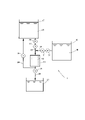
図1は本発明の一実施形態に係る回収システムの構成を概略的に示す。回収システム11は、第1流路12を形成するCDI(Capacitive Deionaization)ユニット13と、第2流路14でCDIユニット13の第1流路12に接続される第1液槽15と、第2流路14に合流する第3流路16でCDIユニット13の第1流路12に接続される第2液槽17とを備える。第1液槽15には、回収したいイオン(例えば金属イオン)を含む溶液18が湛えられる。そういった溶液18には、例えば電解めっき処理で用いられた電解液が含まれることができる。溶液18には、決められた濃度以上でイオン(例えばビスマスといったイオン金属)が含有される。
FIG. 1 schematically shows the configuration of a recovery system according to an embodiment of the present invention. The recovery system 11 includes a CDI (Capacitor Deionization) unit 13 forming the first flow path 12, a first liquid tank 15 connected to the first flow path 12 of the CDI unit 13 by the second flow path 14, and a second liquid tank 15. A second liquid tank 17 connected to the first flow path 12 of the CDI unit 13 by the third flow path 16 joining the flow path 14 is provided. The first liquid tank 15 is filled with a solution 18 containing ions (for example, metal ions) to be recovered. Such a solution 18 can contain, for example, the electrolytic solution used in the electrolytic plating treatment. The solution 18 contains ions (for example, an ionic metal such as bismuth) at a concentration equal to or higher than a predetermined concentration.
第2液槽17には、第1液槽15の溶液18に混合された際に溶液18中のイオンの濃度を低下させることができる希釈液19が湛えられる。そういった希釈液19には例えば水が含まれることができる。希釈液19は溶液18の溶媒であればよい。
The second liquid tank 17 is filled with a diluted liquid 19 that can reduce the concentration of ions in the solution 18 when mixed with the solution 18 of the first liquid tank 15. Such a diluent 19 can contain, for example, water. The diluent 19 may be the solvent of the solution 18.
第2流路14は、第1液槽15からCDIユニット13に至る配管で形成され、決められた濃度以上でイオンを含有する液体の通路を形成する。第3流路16は、第2液槽17から第2流路14の配管に合流する配管で形成され、溶液18の通路に希釈液19の通路を結合し溶液18に希釈液19を混合する。
The second flow path 14 is formed by a pipe from the first liquid tank 15 to the CDI unit 13, and forms a passage for a liquid containing ions at a predetermined concentration or higher. The third flow path 16 is formed by a pipe that joins the pipes of the second liquid tank 17 to the second flow path 14, and connects the passage of the diluent 19 to the passage of the solution 18 to mix the diluted liquid 19 with the solution 18. ..
第2流路14には、通路を流通する溶液18の流量を調整する第1流量制御弁21が配置される。第1流量制御弁21は、例えば制御信号の供給に応じて制御信号で設定される開き度で開く電磁弁で構成されることができる。第1流量制御弁21の開き度に応じて溶液18の流量は調整されることができる。
In the second flow path 14, a first flow rate control valve 21 for adjusting the flow rate of the solution 18 flowing through the passage is arranged. The first flow rate control valve 21 can be composed of, for example, a solenoid valve that opens with an opening degree set by a control signal according to the supply of the control signal. The flow rate of the solution 18 can be adjusted according to the degree of opening of the first flow rate control valve 21.
第3流路16には、通路を流通する希釈液19の流量を調整する第2流量制御弁22が配置される。第2流量制御弁22は、例えば制御信号の供給に応じて制御信号で設定される開き度で開く電磁弁で構成されることができる。第2流量制御弁22の開き度に応じて希釈液19の流量は調整されることができる。
A second flow rate control valve 22 for adjusting the flow rate of the diluent 19 flowing through the passage is arranged in the third flow path 16. The second flow rate control valve 22 can be composed of, for example, a solenoid valve that opens with an opening degree set by a control signal according to the supply of the control signal. The flow rate of the diluent 19 can be adjusted according to the degree of opening of the second flow rate control valve 22.
回収システム11は、CDIユニット13の第1流路12から第2液槽17に至る第4流路24をさらに備える。CDIユニット13から流出する希釈液19は第2液槽17に戻る。第4流路24には、通路を流通する希釈液(以下「戻り希釈液」という)の流量を調整する第1開閉弁25が配置される。第1開閉弁25は、例えば制御信号の供給に応じて開閉する電磁弁で構成されることができる。第1開閉弁25の開閉に応じて戻り希釈液の流通は停止され許容される。
The recovery system 11 further includes a fourth flow path 24 from the first flow path 12 of the CDI unit 13 to the second liquid tank 17. The diluted solution 19 flowing out of the CDI unit 13 returns to the second liquid tank 17. In the fourth flow path 24, a first on-off valve 25 for adjusting the flow rate of the diluent (hereinafter referred to as “return diluent”) flowing through the passage is arranged. The first on-off valve 25 can be composed of, for example, a solenoid valve that opens and closes according to the supply of a control signal. The flow of the return diluent is stopped and allowed according to the opening and closing of the first on-off valve 25.
回収システム11は、CDIユニット13および第1開閉弁25の間で第4流路24から分岐する第5流路26でCDIユニット13の第1流路12に接続される第3液槽27をさらに備える。第3液槽27には、CDIユニット13で脱離されたイオンを含む希釈液(以下「濃縮液」という)が湛えられる。
The recovery system 11 has a third liquid tank 27 connected to the first flow path 12 of the CDI unit 13 by the fifth flow path 26 branching from the fourth flow path 24 between the CDI unit 13 and the first on-off valve 25. Further prepare. The third liquid tank 27 is filled with a diluted liquid (hereinafter referred to as “concentrated liquid”) containing the ions desorbed by the CDI unit 13.
第5流路26には、通路を流通する濃縮液の流量を調整する第2開閉弁28が配置される。第2開閉弁28は、例えば制御信号の供給に応じて開閉する電磁弁で構成されることができる。第2開閉弁28の開閉に応じて濃縮液の流通は停止され許容される。
A second on-off valve 28 for adjusting the flow rate of the concentrated liquid flowing through the passage is arranged in the fifth flow path 26. The second on-off valve 28 can be composed of, for example, a solenoid valve that opens and closes in response to the supply of a control signal. The flow of the concentrated liquid is stopped and allowed according to the opening and closing of the second on-off valve 28.
第2液槽17、第3流路16、CDIユニット13(第1流路12)および第4流路24は循環経路を形成する。希釈液19は循環経路を循環する。循環経路には液流ポンプ29が配置される。液流ポンプ29は決められた圧力で希釈液19の循環を生み出す。液流ポンプ29は例えば第2液槽17と第2流量制御弁22との間で第3流路16に設置されればよい。
The second liquid tank 17, the third flow path 16, the CDI unit 13 (first flow path 12) and the fourth flow path 24 form a circulation path. The diluent 19 circulates in the circulation pathway. A liquid flow pump 29 is arranged in the circulation path. The liquid flow pump 29 creates a circulation of the diluent 19 at a determined pressure. The liquid flow pump 29 may be installed in the third flow path 16 between the second liquid tank 17 and the second flow rate control valve 22, for example.
第2流路14には、第1液槽15から溶液18の流出を促す液流ポンプ31が配置されてもよい。液流ポンプ31は決められた圧力で溶液18を吐出する。液流ポンプ31は例えば第1液槽15と第1流量制御弁21との間で第2流路14に設置されればよい。
A liquid flow pump 31 that promotes the outflow of the solution 18 from the first liquid tank 15 may be arranged in the second flow path 14. The liquid flow pump 31 discharges the solution 18 at a predetermined pressure. The liquid flow pump 31 may be installed in the second flow path 14 between the first liquid tank 15 and the first flow rate control valve 21, for example.
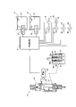
図2に示されるように、回収システム11は、第2流路14に流入する溶液18のイオンの濃度を検出する第1センサー32と、第3流路16に流入する希釈液19のイオンの濃度を検出する第2センサー33と、第1センサー32および第2センサー33に電気的に接続されて、第1センサー32および第2センサー33でそれぞれ検出される濃度に基づき第1流量制御弁21および第2流量制御弁22の開き度を制御する制御回路34とをさらに備える。第1センサー32は例えば第1液槽15に設置されればよい。第2センサー33は例えば第2液槽17に設置されればよい。第1センサー32および第2センサー33は例えばTDS(Total Dissolved Solids)メーターで構成されることができる。
As shown in FIG. 2, the recovery system 11 detects the concentration of the ion of the solution 18 flowing into the second flow path 14, and the ion of the diluted solution 19 flowing into the third flow path 16. The second sensor 33 that detects the concentration is electrically connected to the first sensor 32 and the second sensor 33, and the first flow control valve 21 is based on the concentration detected by the first sensor 32 and the second sensor 33, respectively. Further, a control circuit 34 for controlling the degree of opening of the second flow control valve 22 is provided. The first sensor 32 may be installed in, for example, the first liquid tank 15. The second sensor 33 may be installed in, for example, the second liquid tank 17. The first sensor 32 and the second sensor 33 can be configured with, for example, a TDS (Total Dissolved Solids) meter.
CDIユニット13は、第1流路12を形成する筒体35内に配置される第1電極36および第2電極37を備える。第1電極36および第2電極37は決められた電極間距離DEで離れる。第1電極36および第2電極37は、それぞれ、表裏に活物質38a、38bを保持する導電材シート39で形成される。活物質38a、38bは、例えば導電材シート39の表裏面に貼り付けられる活性炭シートで形成されることができる。導電材シート39にはカーボンシートが用いられることができる。裏側の活物質38bの表面は絶縁体41で覆われる。第1電極36および第2電極37が重ねられると、絶縁体41は第1電極36および第2電極37を絶縁する。絶縁体41はメッシュ構造に構成されることから、第1電極36および第2電極37の間に液体は流通することができる。第1電極36および第2電極37は幾重にも積層されることができる。
The CDI unit 13 includes a first electrode 36 and a second electrode 37 arranged in a tubular body 35 forming the first flow path 12. The first electrode 36 and the second electrode 37 are separated by a predetermined distance between electrodes DE. The first electrode 36 and the second electrode 37 are formed of a conductive material sheet 39 holding active materials 38a and 38b on the front and back surfaces, respectively. The active materials 38a and 38b can be formed of, for example, an activated carbon sheet attached to the front and back surfaces of the conductive material sheet 39. A carbon sheet can be used for the conductive material sheet 39. The surface of the active material 38b on the back side is covered with the insulator 41. When the first electrode 36 and the second electrode 37 are overlapped with each other, the insulator 41 insulates the first electrode 36 and the second electrode 37. Since the insulator 41 has a mesh structure, a liquid can flow between the first electrode 36 and the second electrode 37. The first electrode 36 and the second electrode 37 can be stacked in multiple layers.
絶縁体41は、例えば活性炭シートの表面に貼り合わせられるポリエチレンメッシュと、ポリエチレンメッシュの表面に貼り付けられるPTFE(ポリテトラフルオロエチレン)シートとで形成されることができる。PTFEシートはメッシュ構造に構成される。ポリエチレンメッシュは、仮に活物質38bから破片が生じた際に、第1電極36および第2電極37で絶縁を確保する役割を担う。PTFEシートは、第1電極36および第2電極37の間で距離を確保しながら液体の流路を形成する役割を担う。ポリエチレンメッシュは例えば0.1[mm]の厚みを有することができる。
The insulator 41 can be formed of, for example, a polyethylene mesh attached to the surface of an activated carbon sheet and a PTFE (polytetrafluoroethylene) sheet attached to the surface of the polyethylene mesh. The PTFE sheet has a mesh structure. The polyethylene mesh plays a role of ensuring insulation at the first electrode 36 and the second electrode 37 when debris is generated from the active material 38b. The PTFE sheet plays a role of forming a liquid flow path while ensuring a distance between the first electrode 36 and the second electrode 37. The polyethylene mesh can have a thickness of, for example, 0.1 [mm].
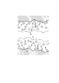
ここでは、図3に示されるように、活物質38a、38bは例えば多孔質体で形成される。第1電極36および第2電極37の間で直流電位が作用すると、細孔42内で活物質38a、38bの表面には電気二重層43が形成される。電気二重層43に基づき細孔42内にイオン44は捕獲される。このとき、電気二重層43の厚み(=debye length κ-1)は次式で与えられる。
Here, as shown in FIG. 3, the active materials 38a and 38b are formed of, for example, a porous body. When a direct current potential acts between the first electrode 36 and the second electrode 37, an electric double layer 43 is formed on the surfaces of the active materials 38a and 38b in the pores 42. Ions 44 are captured in the pores 42 based on the electric double layer 43. At this time, the thickness of the electric double layer 43 (= debye length κ-1) is given by the following equation.

「ε」は液体の誘電率を示し、「k」はBoltzmann定数を示し、「T」は絶対温度を示し、「n」はイオン密度を示し、「e」は電子電荷を示し、「v」はイオンの値数(対イオンの価数)を示す。細孔42内ではイオンの濃度の調整に基づき電気二重層43の干渉は回避されることができる。
"Ε" indicates the permittivity of the liquid, "k" indicates the Boltzmann constant, "T" indicates the absolute temperature, "n" indicates the ion density, "e" indicates the electron charge, and "v". Indicates the number of ion values (counterion valence). Interference of the electric
第1電極36および第2電極37には、第1電極36および第2電極37に直流電力を供給する電源45が接続される。電源45の働きで第1電極36および第2電極37の間に電位は生成される。電源45は、第1流路12で第1電極36から第2電極37に向かって直流電流を形成する第1モードと、第1流路12で第2電極37から第1電極36に向かって直流電流を形成する第2モードとで切り替えられることができる。すなわち、第1モードでは第1電極36は正極として機能し第2電極37は負極として機能する。第2モードでは第1電極36は負極として機能し第2電極37は正極として機能する。電源45の第1モードでは、絶縁体41を流通する液体中の陰イオンは第1電極36の活物質38a、38bに吸着される。液体中の陽イオンは第2電極37の活物質38a、38bに吸着される。第1電極36に付着する陽イオンは第1電極36から脱離する。第2電極37に付着する陰イオンは第2電極37から脱離する。電源45の第2モードでは、絶縁体41を流通する液体中の陰イオンは第2電極37の活物質38a、38bに吸着される。液体中の陽イオンは第1電極36の活物質38a、38bに吸着される。第2電極37に付着する陽イオンは第2電極37から脱離する。第1電極36に付着する陰イオンは第1電極36から脱離する。ここでは、絶縁体41は例えば第1電極36および第2電極37の間に少なくとも10[mm]の電極間距離DEを保持する。電極間距離DEが10[mm]を超えると、液体の流通時に電気抵抗値が過度に増大してしまい、陰イオンおよび陽イオンの吸着に十分な電流が確保されることができない。
A power supply 45 for supplying DC power to the first electrode 36 and the second electrode 37 is connected to the first electrode 36 and the second electrode 37. A potential is generated between the first electrode 36 and the second electrode 37 by the action of the power supply 45. The power supply 45 has a first mode in which a direct current is formed from the first electrode 36 toward the second electrode 37 in the first flow path 12, and a first mode in which a direct current is formed from the second electrode 37 toward the first electrode 36 in the first flow path 12. It can be switched with the second mode that forms a direct current. That is, in the first mode, the first electrode 36 functions as a positive electrode and the second electrode 37 functions as a negative electrode. In the second mode, the first electrode 36 functions as a negative electrode and the second electrode 37 functions as a positive electrode. In the first mode of the power supply 45, the anions in the liquid flowing through the insulator 41 are adsorbed by the active materials 38a and 38b of the first electrode 36. The cations in the liquid are adsorbed on the active materials 38a and 38b of the second electrode 37. The cations adhering to the first electrode 36 are desorbed from the first electrode 36. Anions adhering to the second electrode 37 are desorbed from the second electrode 37. In the second mode of the power supply 45, the anions in the liquid flowing through the insulator 41 are adsorbed by the active materials 38a and 38b of the second electrode 37. The cations in the liquid are adsorbed on the active materials 38a and 38b of the first electrode 36. The cations adhering to the second electrode 37 are desorbed from the second electrode 37. Anions adhering to the first electrode 36 are desorbed from the first electrode 36. Here, the insulator 41 holds, for example, an inter-electrode distance DE of at least 10 [mm] between the first electrode 36 and the second electrode 37. If the distance DE between the electrodes exceeds 10 [mm], the electric resistance value increases excessively during the flow of the liquid, and a sufficient current cannot be secured for the adsorption of anions and cations.
制御回路34には、第1センサー32および第2センサー33のほか、第1流量制御弁21や第2流量制御弁22、第1開閉弁25、第2開閉弁28、液流ポンプ29、31が電気的に接続される。制御回路34は、第1流量制御弁21や第2流量制御弁22、第1開閉弁25、第2開閉弁28、液流ポンプ29、31の制御信号を生成する。制御回路34は、第1流量制御弁21および第2流量制御弁22の開き度の設定にあたって、第2流路14から第1流路12に流入する溶液18と、第3流路16から第1流路12に流入する希釈液19との混合比を算出する。この混合比に基づき、決められた濃度未満でイオンを含有する液体が確立される。加えて、イオンの濃度は決められた閾値以上に維持される。ここでは、制御回路34、第1流量制御弁21および第2流量制御弁22は、第1流路12に流入する液体に含まれるイオンの濃度を決められた閾値以上に維持する濃度制御装置として機能する。濃度制御装置はCDIユニット13に組み合わせられてCDI装置を構成する。
In addition to the first sensor 32 and the second sensor 33, the control circuit 34 includes a first flow rate control valve 21, a second flow rate control valve 22, a first on-off valve 25, a second on-off valve 28, and a liquid flow pump 29, 31. Is electrically connected. The control circuit 34 generates control signals for the first flow rate control valve 21, the second flow rate control valve 22, the first on-off valve 25, the second on-off valve 28, and the liquid flow pumps 29 and 31. The control circuit 34 sets the degree of opening of the first flow rate control valve 21 and the second flow rate control valve 22 with the solution 18 flowing from the second flow path 14 into the first flow path 12 and the third flow rate control valve 16 to the first. 1 The mixing ratio with the diluent 19 flowing into the flow path 12 is calculated. Based on this mixing ratio, a liquid containing ions below a predetermined concentration is established. In addition, the ion concentration is maintained above a fixed threshold. Here, the control circuit 34, the first flow rate control valve 21, and the second flow rate control valve 22 serve as concentration control devices for maintaining the concentration of ions contained in the liquid flowing into the first flow path 12 to a predetermined threshold value or higher. Function. The concentration control device is combined with the CDI unit 13 to form the CDI device.
制御回路34は、検出されるイオンの濃度に応じて決められる上限値未満に第1電極36および第2電極37に印加される電位を制御する。電位の制御にあたって制御回路34は第1センサー32および第2センサー33の検出値から第1流路12に流入する液体の導電率を算出する。制御回路34は、算出された導電率に基づき決定される電位の上限値を特定する制御信号を生成する。生成された制御信号は電源45に供給される。
The control circuit 34 controls the potential applied to the first electrode 36 and the second electrode 37 to be less than the upper limit value determined according to the concentration of the detected ion. In controlling the potential, the control circuit 34 calculates the conductivity of the liquid flowing into the first flow path 12 from the detected values of the first sensor 32 and the second sensor 33. The control circuit 34 generates a control signal that specifies an upper limit of the potential determined based on the calculated conductivity. The generated control signal is supplied to the power supply 45.
次に回収システム11の動作を説明する。制御回路34では吸着モードが設定される。吸着モードでは第1開閉弁25は開放され第2開閉弁28は閉じられる。第2液槽17には希釈液19が導入される。液流ポンプ29が作動すると、希釈液19は第2液槽17、第3流路16、CDIユニット13(第1流路12)および第4流路24を循環する。
Next, the operation of the recovery system 11 will be described. The adsorption mode is set in the control circuit 34. In the suction mode, the first on-off valve 25 is opened and the second on-off valve 28 is closed. The diluent 19 is introduced into the second liquid tank 17. When the liquid flow pump 29 operates, the diluted liquid 19 circulates in the second liquid tank 17, the third flow path 16, the CDI unit 13 (first flow path 12), and the fourth flow path 24.
第1液槽15には溶液18が導入される。液流ポンプ31が作動すると、第2流路14に溶液18は流入する。このとき、制御回路34は第1流量制御弁21の開き度と第2流量制御弁22の開き度とを制御する。こうして溶液18の流量と希釈液19の流量とが調整されることで、第1流路12に流入する液体ではイオンの濃度は決められた濃度未満に設定される。流量の調整にあたって制御回路34は第1センサー32および第2センサー33から検出信号を受領する。検出信号では例えば導電率に基づきイオンの濃度は特定される。
The solution 18 is introduced into the first liquid tank 15. When the liquid flow pump 31 operates, the solution 18 flows into the second flow path 14. At this time, the control circuit 34 controls the opening degree of the first flow rate control valve 21 and the opening degree of the second flow rate control valve 22. By adjusting the flow rate of the solution 18 and the flow rate of the diluted solution 19 in this way, the concentration of ions in the liquid flowing into the first flow path 12 is set to be less than a predetermined concentration. In adjusting the flow rate, the control circuit 34 receives detection signals from the first sensor 32 and the second sensor 33. In the detection signal, for example, the ion concentration is specified based on the conductivity.
制御回路34は電源45に第1モードを設定する。第1電極36(正極)および第2電極37(負極)の間で直流電位が作用すると、活物質38a、38bの細孔42内で活物質38a、38bの表面には電気二重層43が形成される。電気二重層43に基づき細孔42内にイオン44は捕獲される。第1流路12を流通する液体から第1電極36および第2電極37にイオンが吸着される。第1流路12ではイオンの濃度は決められた濃度未満に設定されることから、活物質38a、38bは効率的にイオンを吸着することができる。
The control circuit 34 sets the first mode to the power supply 45. When a direct current potential acts between the first electrode 36 (positive electrode) and the second electrode 37 (negative electrode), an electric double layer 43 is formed on the surface of the active materials 38a and 38b in the pores 42 of the active materials 38a and 38b. Will be done. Ions 44 are captured in the pores 42 based on the electric double layer 43. Ions are adsorbed on the first electrode 36 and the second electrode 37 from the liquid flowing through the first flow path 12. Since the ion concentration is set to less than a predetermined concentration in the first flow path 12, the active materials 38a and 38b can efficiently adsorb ions.
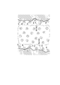
このとき、第1流路12に流入する液体ではイオンの濃度は決められた閾値以上に維持されることから、活物質38a、38bの表面では電気二重層43の厚みは細孔42の大きさに応じて決められた厚み以下に抑えられることができる。その結果、細孔42内で電気二重層43の干渉は回避されることができる。こうして細孔42内で良好に電気二重層43は維持されることができる。活物質38a、38bは効率的にイオンを吸着することができる。その一方で、仮にイオンの濃度が決められた閾値を下回ると、図4に示されるように、細孔42内で電気二重層の厚みが増大し、電気二重層の干渉47が生じる。こうした電気二重層の干渉47はイオンの吸着を阻害する。吸着の効率は低下してしまう。
At this time, since the ion concentration is maintained above a predetermined threshold value in the liquid flowing into the first flow path 12, the thickness of the electric double layer 43 on the surfaces of the active materials 38a and 38b is the size of the pores 42. It can be suppressed to the thickness or less determined according to the above. As a result, the interference of the electric double layer 43 in the pores 42 can be avoided. In this way, the electric double layer 43 can be well maintained in the pores 42. The active substances 38a and 38b can efficiently adsorb ions. On the other hand, if the ion concentration falls below a predetermined threshold, the thickness of the electric double layer increases in the pores 42, and interference 47 of the electric double layer occurs, as shown in FIG. The interference 47 of such an electric double layer inhibits the adsorption of ions. The efficiency of adsorption will decrease.
続いて制御回路34では脱離モードが設定される。脱離モードでは第1開閉弁25は閉じられ第2開閉弁28は開かれる。液流ポンプ29が作動すると、希釈液19は第2液槽17から第3流路16、CDIユニット13(第1流路12)および第5流路26を経て第3液槽27に流入する。液流ポンプ31は停止する。第1流量制御弁21は閉じる。
Subsequently, the detachment mode is set in the control circuit 34. In the detachment mode, the first on-off valve 25 is closed and the second on-off valve 28 is opened. When the liquid flow pump 29 operates, the diluted liquid 19 flows from the second liquid tank 17 into the third liquid tank 27 via the third flow path 16, the CDI unit 13 (first flow path 12) and the fifth flow path 26. .. The liquid flow pump 31 is stopped. The first flow control valve 21 is closed.
ここでは、制御回路34は電源45に第2モードを設定する。第1電極36および第2電極37では正極および負極は入れ替わる。第1電極36(負極)および第2電極37(正極)の間で直流電位が形成されると、第1流路12を流通する希釈液19に第1電極36および第2電極37からイオンが脱離する。濃縮液は第3液槽27に流入する。こうしてイオンは濃縮液として回収される。
Here, the control circuit 34 sets the second mode to the power supply 45. In the first electrode 36 and the second electrode 37, the positive electrode and the negative electrode are interchanged. When a direct current potential is formed between the first electrode 36 (negative electrode) and the second electrode 37 (positive electrode), ions are emitted from the first electrode 36 and the second electrode 37 into the diluted solution 19 flowing through the first flow path 12. Detach. The concentrated liquid flows into the third liquid tank 27. In this way, the ions are recovered as a concentrate.
本実施形態に係る回収システム11は、溶液18に希釈液19を混合し、第1流路12に向かって決められた濃度未満でイオンを含有する液体を導入する第3流路16を備える。正極および負極の間で直流電位が形成されると、第1流路12を流通する液体から正極および負極にはイオンが吸着される。第1流路12ではイオンの濃度は決められた濃度未満に設定されることから、イオンの析出は良好に回避され(抑制され)ることができる。正極および負極からイオンは効率的に回収されることができる。
The recovery system 11 according to the present embodiment includes a third flow path 16 in which the diluted solution 19 is mixed with the solution 18 and a liquid containing ions at a concentration lower than a predetermined concentration is introduced toward the first flow path 12. When a DC potential is formed between the positive electrode and the negative electrode, ions are adsorbed from the liquid flowing through the first flow path 12 to the positive electrode and the negative electrode. Since the concentration of ions is set to less than a predetermined concentration in the first flow path 12, precipitation of ions can be satisfactorily avoided (suppressed). Ions can be efficiently recovered from the positive and negative electrodes.
本実施形態では、第2流路14に流入する溶液18のイオンの濃度を検出する第1センサー32と、第3流路16に流入する希釈液19のイオンの濃度を検出する第2センサー33と、第2流路14に配置されて、通路を流通する溶液18の流量を調整する第1流量制御弁21と、第3流路16に配置されて、通路を流通する希釈液19の流量を調整する第2流量制御弁22とを備える。制御回路34は、第1センサー32および第2センサー33でそれぞれ検出される濃度に基づき第1流量制御弁21および第2流量制御弁22の開き度を制御する。溶液18に含まれるイオンの濃度と、希釈液19に含まれるイオンの濃度とに基づき第1流量制御弁21および第2流量制御弁22の開き度は制御される。こうして溶液18と希釈液19との混ざり具合は調整される。第1流路12に流入する液体に含まれるイオンの濃度は調整されることができる。
In the present embodiment, the first sensor 32 that detects the concentration of the ion of the solution 18 flowing into the second flow path 14 and the second sensor 33 that detects the concentration of the ion of the diluted solution 19 flowing into the third flow path 16. The flow rate of the first flow rate control valve 21 arranged in the second flow path 14 to adjust the flow rate of the solution 18 flowing through the passage, and the flow rate of the diluent 19 arranged in the third flow path 16 and flowing through the passage. It is provided with a second flow rate control valve 22 for adjusting. The control circuit 34 controls the degree of opening of the first flow rate control valve 21 and the second flow rate control valve 22 based on the concentrations detected by the first sensor 32 and the second sensor 33, respectively. The degree of opening of the first flow rate control valve 21 and the second flow rate control valve 22 is controlled based on the concentration of ions contained in the solution 18 and the concentration of ions contained in the diluted solution 19. In this way, the mixing condition of the solution 18 and the diluted solution 19 is adjusted. The concentration of ions contained in the liquid flowing into the first flow path 12 can be adjusted.
本実施形態では、イオンの吸着にあたってCDIユニット13への導入に先立ち希釈液19に溶液18は混合される。仮に回収する溶液18の流量や総量が少なくても、希釈液19で十分に第1流路12を流通する液体の流量は確保されることができる。第1流路12では第1電極36および第2電極37は流通する液体に浸ることができる。こうしてイオンは効率的に吸着されることができる。気体に対して活物質38a、38bの暴露は回避されることができる。
In this embodiment, the solution 18 is mixed with the diluted solution 19 prior to introduction into the CDI unit 13 for ion adsorption. Even if the flow rate or the total amount of the recovered solution 18 is small, the diluted solution 19 can sufficiently secure the flow rate of the liquid flowing through the first flow path 12. In the first flow path 12, the first electrode 36 and the second electrode 37 can be immersed in the flowing liquid. In this way, the ions can be efficiently adsorbed. Exposure of the active substances 38a, 38b to the gas can be avoided.
本実施形態に係る回収システム11では、希釈液19および溶液18の混合に基づきCDIユニット13に流入する液体のイオンの濃度は調整されることができる。溶液18の希釈化に応じてCDIユニット13から流出する液体のイオンの濃度は第2液槽17内の希釈液19のそれに合わせ込まれることができる。こうしてイオンの吸着時でも第2液槽17内では希釈液19のイオンは一定の濃度に維持されることができる。第2液槽17ではイオンの滞留は回避されることができる。溶液18からイオンの全量は回収されることができる。
In the recovery system 11 according to the present embodiment, the concentration of the ions of the liquid flowing into the CDI unit 13 can be adjusted based on the mixture of the diluted solution 19 and the solution 18. The concentration of the ions of the liquid flowing out of the CDI unit 13 in response to the dilution of the solution 18 can be adjusted to that of the diluted solution 19 in the second liquid tank 17. In this way, the ions of the diluted solution 19 can be maintained at a constant concentration in the second liquid tank 17 even when the ions are adsorbed. In the second liquid tank 17, the retention of ions can be avoided. The entire amount of ions can be recovered from solution 18.
本実施形態に係る制御回路34は、第1センサー32および第2センサー33の検出値から第1流路12に流入する液体の導電率を算出し、算出された導電率に基づき第1電極36および第2電極37に印加される電位を制御する。イオンの濃度に応じて液体の導電率が変化しても、第1電極36および第2電極37に印加される電位は上限値未満に制御されるので、水の電気分解は回避されることができる。水溶液の導電率はイオンの濃度の上昇に応じて高まることから、イオンの濃度が高まるにつれて上限値は高く設定されることができ、その結果、効率的にイオンの吸着は実現されることができる。
Thecontrol circuit 34 according to the present embodiment calculates the conductivity of the liquid flowing into the first flow path 12 from the detection values of the first sensor 32 and the second sensor 33, and the first electrode 36 is based on the calculated conductivity. And the potential applied to the second electrode 37 is controlled. Even if the conductivity of the liquid changes according to the concentration of ions, the potential applied to the first electrode 36 and the second electrode 37 is controlled to be less than the upper limit, so that electrolysis of water can be avoided. can. Since the conductivity of the aqueous solution increases as the ion concentration increases, the upper limit can be set higher as the ion concentration increases, and as a result, ion adsorption can be efficiently realized. ..
The
Claims (1)
- 活物質を向き合わせてそれらの間に流路を形成し、細孔内で活物質の表面に形成される電気二重層に基づきイオンを吸着する正極および負極と、
前記流路に流入する液体に含まれるイオンの濃度を決められた閾値以上に維持する濃度制御装置と、
検出されるイオンの濃度に応じて決められる上限値未満に前記正極および前記負極に印加される電位を制御する制御回路と、
を備えることを特徴とするCDI装置。
Positive and negative electrodes that face the active materials to form a flow path between them and adsorb ions based on the electric double layer formed on the surface of the active material in the pores.
A concentration control device that maintains the concentration of ions contained in the liquid flowing into the flow path above a predetermined threshold value, and
A control circuit that controls the potential applied to the positive electrode and the negative electrode below the upper limit value determined according to the concentration of detected ions, and
A CDI device comprising.
Priority Applications (3)
| Application Number | Priority Date | Filing Date | Title |
|---|---|---|---|
| EP21889243.8A EP4242178A4 (en) | 2020-11-06 | 2021-11-04 | Cdi device |
| CN202180074792.5A CN116547242A (en) | 2020-11-06 | 2021-11-04 | CDI device |
| US18/143,568 US20230271856A1 (en) | 2020-11-06 | 2023-05-04 | Cdi device |
Applications Claiming Priority (2)
| Application Number | Priority Date | Filing Date | Title |
|---|---|---|---|
| JP2020186071A JP7089570B2 (en) | 2020-11-06 | 2020-11-06 | CDI device |
| JP2020-186071 | 2020-11-06 |
Related Child Applications (1)
| Application Number | Title | Priority Date | Filing Date |
|---|---|---|---|
| US18/143,568 Continuation US20230271856A1 (en) | 2020-11-06 | 2023-05-04 | Cdi device |
Publications (1)
| Publication Number | Publication Date |
|---|---|
| WO2022097691A1 true WO2022097691A1 (en) | 2022-05-12 |
Family
ID=81458371
Family Applications (1)
| Application Number | Title | Priority Date | Filing Date |
|---|---|---|---|
| PCT/JP2021/040645 WO2022097691A1 (en) | 2020-11-06 | 2021-11-04 | Cdi device |
Country Status (5)
| Country | Link |
|---|---|
| US (1) | US20230271856A1 (en) |
| EP (1) | EP4242178A4 (en) |
| JP (1) | JP7089570B2 (en) |
| CN (1) | CN116547242A (en) |
| WO (1) | WO2022097691A1 (en) |
Families Citing this family (1)
| Publication number | Priority date | Publication date | Assignee | Title |
|---|---|---|---|---|
| JP2023164037A (en) | 2022-04-28 | 2023-11-10 | セイコーエプソン株式会社 | Piezoelectric actuator, manufacturing method thereof, droplet discharge head, and ultrasonic device |
Citations (5)
| Publication number | Priority date | Publication date | Assignee | Title |
|---|---|---|---|---|
| JP2002273439A (en) * | 2001-03-22 | 2002-09-24 | Kurita Water Ind Ltd | Desalting method and device therefor |
| JP2014108377A (en) * | 2012-11-30 | 2014-06-12 | Panasonic Corp | Water treatment equipment |
| JP2014124483A (en) * | 2012-12-27 | 2014-07-07 | Nomura Micro Sci Co Ltd | Method of sterilizing pure water production apparatus for pharmaceuticals and pure water production apparatus for pharmaceuticals |
| JP6570692B1 (en) | 2018-04-16 | 2019-09-04 | 株式会社タクマ | Waste water treatment method and waste water treatment system using electric double layer |
| WO2019193901A1 (en) * | 2018-04-05 | 2019-10-10 | 三菱電機株式会社 | Water treatment device and water treatment method |
Family Cites Families (3)
| Publication number | Priority date | Publication date | Assignee | Title |
|---|---|---|---|---|
| JP3846536B2 (en) * | 1999-12-06 | 2006-11-15 | 三菱電機株式会社 | Ion remover |
| JP2002336864A (en) * | 2001-05-11 | 2002-11-26 | Kurita Water Ind Ltd | Desalted water making method and desalted water making apparatus |
| JP2005219045A (en) * | 2004-01-09 | 2005-08-18 | Air Water Inc | Method and apparatus for controlling liquid quantity of solution |
-
2020
- 2020-11-06 JP JP2020186071A patent/JP7089570B2/en active Active
-
2021
- 2021-11-04 WO PCT/JP2021/040645 patent/WO2022097691A1/en active Application Filing
- 2021-11-04 EP EP21889243.8A patent/EP4242178A4/en active Pending
- 2021-11-04 CN CN202180074792.5A patent/CN116547242A/en active Pending
-
2023
- 2023-05-04 US US18/143,568 patent/US20230271856A1/en active Pending
Patent Citations (5)
| Publication number | Priority date | Publication date | Assignee | Title |
|---|---|---|---|---|
| JP2002273439A (en) * | 2001-03-22 | 2002-09-24 | Kurita Water Ind Ltd | Desalting method and device therefor |
| JP2014108377A (en) * | 2012-11-30 | 2014-06-12 | Panasonic Corp | Water treatment equipment |
| JP2014124483A (en) * | 2012-12-27 | 2014-07-07 | Nomura Micro Sci Co Ltd | Method of sterilizing pure water production apparatus for pharmaceuticals and pure water production apparatus for pharmaceuticals |
| WO2019193901A1 (en) * | 2018-04-05 | 2019-10-10 | 三菱電機株式会社 | Water treatment device and water treatment method |
| JP6570692B1 (en) | 2018-04-16 | 2019-09-04 | 株式会社タクマ | Waste water treatment method and waste water treatment system using electric double layer |
Non-Patent Citations (1)
| Title |
|---|
| SHINNOSUKE USUI ET AL.: "Dispersion and aggregation of fine particles", JOURNAL RESOURCES AND MATERIALS OF JAPAN, vol. 107, 25 December 1991 (1991-12-25), pages 585 - 591 |
Also Published As
| Publication number | Publication date |
|---|---|
| EP4242178A1 (en) | 2023-09-13 |
| EP4242178A4 (en) | 2024-05-01 |
| JP7089570B2 (en) | 2022-06-22 |
| CN116547242A (en) | 2023-08-04 |
| US20230271856A1 (en) | 2023-08-31 |
| JP2022075340A (en) | 2022-05-18 |
Similar Documents
| Publication | Publication Date | Title |
|---|---|---|
| Huang et al. | Investigation of pH-dependent phosphate removal from wastewaters by membrane capacitive deionization (MCDI) | |
| US20080057398A1 (en) | Non-faraday based systems, devices and methods for removing ionic species from liquid | |
| JP3349710B2 (en) | Electrolyzer and electrolyzed water generator | |
| JP4394957B2 (en) | Water purification apparatus and method | |
| US8062485B2 (en) | Water treatment device | |
| WO2015154708A1 (en) | Water electrolysis cup | |
| WO2022097691A1 (en) | Cdi device | |
| JP4600225B2 (en) | Electrolyzed water generator | |
| JP2000091169A (en) | Liquid-passable capacitor and method of treating liquid using the same | |
| JP2000087299A (en) | Substrate plating apparatus | |
| WO2022097690A1 (en) | Recovery system | |
| JP2012107331A (en) | Water electrolysis system | |
| JP2002273439A (en) | Desalting method and device therefor | |
| JP2007054762A (en) | Electrolytic water generator | |
| JP2002273432A (en) | Device for producing desalted water and method of producing desalted water | |
| JP2002336864A (en) | Desalted water making method and desalted water making apparatus | |
| JP6982668B1 (en) | Purification device | |
| JP2008178771A (en) | Electrolytic water generator | |
| JP3774033B2 (en) | Ozone water generator | |
| JPH0318924B2 (en) | ||
| WO2023137220A1 (en) | Process and apparatus for high recovery in electrodialysis and electrodeionization systems | |
| KR20210080073A (en) | Water treatment system | |
| JP2002343689A (en) | Regeneration method of liquid passing type electric double-layer capacitor | |
| CN116621280A (en) | Device for treating thallium-containing wastewater by means of electro-adsorption coupling bipolar membrane | |
| JP2017051907A (en) | Ion concentration adjusting device and ion concentration adjustment method |
Legal Events
| Date | Code | Title | Description |
|---|---|---|---|
| 121 | Ep: the epo has been informed by wipo that ep was designated in this application |
Ref document number: 21889243 Country of ref document: EP Kind code of ref document: A1 |
|
| WWE | Wipo information: entry into national phase |
Ref document number: 202180074792.5 Country of ref document: CN |
|
| NENP | Non-entry into the national phase |
Ref country code: DE |
|
| ENP | Entry into the national phase |
Ref document number: 2021889243 Country of ref document: EP Effective date: 20230606 |