JP2012107331A - Water electrolysis system - Google Patents
Water electrolysis system Download PDFInfo
- Publication number
- JP2012107331A JP2012107331A JP2011233910A JP2011233910A JP2012107331A JP 2012107331 A JP2012107331 A JP 2012107331A JP 2011233910 A JP2011233910 A JP 2011233910A JP 2011233910 A JP2011233910 A JP 2011233910A JP 2012107331 A JP2012107331 A JP 2012107331A
- Authority
- JP
- Japan
- Prior art keywords
- water
- water electrolysis
- electrolytic solution
- anode
- concentration
- Prior art date
- Legal status (The legal status is an assumption and is not a legal conclusion. Google has not performed a legal analysis and makes no representation as to the accuracy of the status listed.)
- Pending
Links
Images

Abstract
Description
本発明は、水電解システムに関し、特に水を電気分解で処理する水電解システムに関する。 The present invention relates to a water electrolysis system, and more particularly to a water electrolysis system for treating water by electrolysis.
水を電気分解する技術として電解装置が知られている。従来の電解装置は、イオン伝導膜(固体(高分子)電解質膜)の一方の面が陽極に接し、他方の面が陰極に接するというサンドウィッチ構造を用いている。すなわち、イオン伝導膜の両面は、それぞれ陽極及び陰極に密着している。このような構造の電解装置で水の電気分解を行う場合、陰極側では水素が発生し、陽極側では酸素が発生する。従って、発生した水素や酸素を逃がすために、陰極及び陽極として多孔体状や網状の電極を用いることは不可欠である。そのような構造の一例として、特開2004−353033号公報(以下、特許文献1という)が挙げられる。 An electrolyzer is known as a technique for electrolyzing water. A conventional electrolysis apparatus uses a sandwich structure in which one surface of an ion conductive membrane (solid (polymer) electrolyte membrane) is in contact with the anode and the other surface is in contact with the cathode. That is, both surfaces of the ion conductive film are in close contact with the anode and the cathode, respectively. When electrolysis of water is performed in an electrolytic apparatus having such a structure, hydrogen is generated on the cathode side and oxygen is generated on the anode side. Therefore, in order to release generated hydrogen and oxygen, it is indispensable to use porous or net-like electrodes as the cathode and the anode. As an example of such a structure, there is JP-A-2004-353033 (hereinafter referred to as Patent Document 1).
特許文献1には、水の電気分解用膜・電極接合体およびそれを用いた水の電気分解装置が開示されている。この水の電気分解用膜・電極接合体は、固体高分子電解質膜と、該固体高分子電解質膜の一方側に接合された酸素極と、他方側に接合された水素極とを含む。酸素極は、イリジウムめっきされた多孔性のシート状カーボン素材と、固体高分子電解質膜に接する側のシート状カーボン素材の面に対してなされたカーボンと固体高分子膜用樹脂を含む混合物のコーティング層とを含む。水素極は、多孔性のシート状カーボン素材と、シート状カーボン素材に対してなされたカーボンおよび固体高分子膜用樹脂を含む混合物のコーティング層と、このコーティング層に対してさらにPt(合金)および/またはPt(合金)担持カーボンと固体高分子膜用樹脂を含む混合物のコーティング層とを含む。すなわち、この例では、多孔性のシート状カーボン素材を主体とした水素極(陰極)及び酸素極(陽極)を用いている。
上記のような構造において、例えば、イオン伝導膜と陰極とが密着した部分を詳細に観察すると、イオン伝導膜と陰極とが接触している部分と接触していない部分とが混在する。そのため、イオン伝導膜と陰極とが密着した部分では、電界の不均衡が発生していると考えられる。すなわち、イオン伝導膜内には、局所的に電界が集中する部分が存在すると考えられる。この電界集中により、イオン伝導膜内での電圧ロスが増大し、電界効率が低下し、更には、電解装置の劣化が引き起こされる原因となっていると考えられる。 In the structure as described above, for example, when a portion where the ion conductive film and the cathode are in close contact is observed in detail, a portion where the ion conductive film and the cathode are in contact with a portion where the ion conductive film and the cathode are in contact with each other are mixed. Therefore, it is considered that an electric field imbalance occurs in the portion where the ion conductive film and the cathode are in close contact. That is, it is considered that there is a portion where the electric field concentrates locally in the ion conductive film. This concentration of electric field is thought to increase the voltage loss in the ion conductive film, lower the electric field efficiency, and further cause deterioration of the electrolysis apparatus.
その劣化を抑制する技術として、特開2010−059514号公報(以下、特許文献2という)に水電解装置及び水電解システムが開示されている。この水電解装置は、固体電解質膜と、陽極と、陰極と、流路とを具備している。固体電解質膜は、第1の面と、第1の面と反対側の第2の面とを有している。陽極は、第1の面の側に、第1の面に接して設けられ、水が流通可能である。陰極は、第2の面の側に、第2の面から離れて設けられている。流路は、陰極と第2の面との間に設けられ、電解液が介在可能である。 As a technique for suppressing such deterioration, a water electrolysis apparatus and a water electrolysis system are disclosed in JP 2010-059514 A (hereinafter referred to as Patent Document 2). This water electrolysis apparatus includes a solid electrolyte membrane, an anode, a cathode, and a flow path. The solid electrolyte membrane has a first surface and a second surface opposite to the first surface. The anode is provided on the first surface side in contact with the first surface and allows water to flow therethrough. The cathode is provided on the second surface side away from the second surface. The flow path is provided between the cathode and the second surface, and an electrolytic solution can be interposed therebetween.
特許文献2は、上記特許文献1のような従来構造の電解装置での劣化メカニズムが少なくとも二種類あると指摘している。第1の劣化のメカニズムは、陽極側からイオン導電膜中を移動してくる陽イオンのうち、水素やアルカリ金属を除く陽イオンが、陰極側の電界集中部分において析出し、そのイオン伝導膜の陰極側で析出した物質(主に金属)が、イオン伝導膜を破壊したり、イオン伝導膜中のイオン伝導を妨げたりする、というものである。この劣化は、主に電解装置の運転中に発生する。第2の劣化のメカニズムは、陽極で発生し、イオン伝導膜内を陰極へ移動して、陰極で水素となって遊離するはずの水素イオンが、電源遮断(電源オフ)時に、陰極からイオン伝導膜内を陽極へ移動して、陽極と反応することで陽極の触媒活性を低下させる、というものである。この劣化は、主に電解装置の運転終了後に発生する。これら2つの劣化原因により、電解装置の動作時間に対応して劣化が進みつつ(第1の劣化のメカニズム)、動作の断続によって急激に劣化する(第2の劣化のメカニズム)という現象が起きていた。しかし、特許文献2の水電解装置及びそれを用いた水電解システムは、上述の構成を有することにより、その二種類の劣化のいずれも抑制することができる。
Patent Document 2 points out that there are at least two types of degradation mechanisms in the conventional electrolyzer as in
上記の特許文献2の水電解システムの構成のように、陰極と固体電解質膜とを離し、その間(流路)を電解液で満たすことにより、電極の寿命の向上と電解能率の向上を図ることができる。しかしながら、更に電極寿命及び電解能率の向上ができれば実用上非常に有用である。研究の結果、発明者は、今回初めて、以下の劣化のメカニズムを見出した。すなわち、電解中に陽極の表面に酸化物(例えば白金の場合、PtOやPtO2)が形成され、それが電解能率の低下に大きく関与している、というメカニズムである。その酸化物の劣化への影響として、電解を行っていく過程で酸化物層が増大して電気抵抗が増大すること、及び、形成される酸化層の触媒能力が低いことが見出された。更に、長時間電解を行っていくと、陽極表面の酸化層に更に酸素が侵入し、酸化層がポーラスになって行き、電気抵抗も更に増加し、陽極と電解膜との接触も更に阻害されることも見出された。 As in the configuration of the water electrolysis system of Patent Document 2, the cathode and the solid electrolyte membrane are separated from each other, and the space (flow path) between them is filled with the electrolytic solution, thereby improving the life of the electrode and the electrolytic efficiency. Can do. However, if the electrode life and electrolytic efficiency can be further improved, it is very useful in practice. As a result of the research, the inventor found the following degradation mechanism for the first time. That is, this is a mechanism in which an oxide (for example, PtO or PtO 2 in the case of platinum) is formed on the surface of the anode during electrolysis, which is largely involved in a decrease in electrolytic efficiency. As an influence on the deterioration of the oxide, it has been found that in the process of electrolysis, the oxide layer increases and the electric resistance increases, and the oxide layer formed has a low catalytic ability. Furthermore, when electrolysis is performed for a long time, oxygen further penetrates into the oxide layer on the anode surface, the oxide layer becomes porous, the electrical resistance further increases, and the contact between the anode and the electrolyte membrane is further inhibited. It was also found.
従って、本発明の目的は、水を電気分解で処理するとき、水電解のセルの電極寿命を向上させることが可能な水電解システムを提供することにある。また、本発明の他の目的は、水を電気分解で処理するとき、水電解のセル内、特に陽極近傍で発生する劣化現象を抑制可能な水電解システムを提供することにある。また、本発明の他の目的は、水を電気分解で処理するとき、水電解のセルの電解効率を向上させることが可能な水電解システムを提供することにある。 Accordingly, an object of the present invention is to provide a water electrolysis system capable of improving the electrode life of a water electrolysis cell when water is electrolyzed. Another object of the present invention is to provide a water electrolysis system capable of suppressing a deterioration phenomenon that occurs in a water electrolysis cell, particularly in the vicinity of an anode, when water is electrolyzed. Another object of the present invention is to provide a water electrolysis system capable of improving the electrolysis efficiency of a water electrolysis cell when water is electrolyzed.
この発明のこの目的とそれ以外の目的と利益とは以下の説明と添付図面とによって容易に確認することができる。 This object and other objects and advantages of the present invention can be easily confirmed by the following description and attached drawings.
以下に、発明を実施するための形態で使用される番号・符号を用いて、課題を解決するための手段を説明する。これらの番号・符号は、特許請求の範囲の記載と発明を実施するための形態との対応関係を明らかにするために括弧付きで付加されたものである。ただし、それらの番号・符号を、特許請求の範囲に記載されている発明の技術的範囲の解釈に用いてはならない。 Hereinafter, means for solving the problem will be described using the numbers and symbols used in the embodiments for carrying out the invention. These numbers and symbols are added with parentheses in order to clarify the correspondence between the description of the claims and the mode for carrying out the invention. However, these numbers and symbols should not be used for interpreting the technical scope of the invention described in the claims.
本発明の水電解システムは、水供給部(90)と、電解液供給部(89)と、水電解装置(1)とを具備している。水供給部(90)は、水を供給する。電解液供給部(89)は、電解液を供給する。水電解装置(1)は、水と電解液とを供給され、水を電気分解する処理を実行し、処理後の水を送出する。水電解装置(1)は、固体電解質膜(10)と、陽極(4)と、陰極(8)と、流路(3c)とを備えている。固体電解質膜(10)は、第1の面(10a)と、第1の面(10a)と反対側の第2の面(10b)とを有する。陽極(4)は、第1の面(10a)の側に、第1の面(10a)に接して設けられ、水が流通する。陰極(8)は、第2の面(10b)の側に、第2の面(10b)から離れて設けられている。流路(3c)は、陰極(8)と第2の面(10b)との間に設けられ、電解液が流通する。電解液は、塩素イオンを含んでいる。塩素イオンの濃度は、50mg/L以上飽和濃度以下である。 The water electrolysis system of the present invention includes a water supply unit (90), an electrolytic solution supply unit (89), and a water electrolysis device (1). The water supply unit (90) supplies water. The electrolytic solution supply unit (89) supplies an electrolytic solution. The water electrolysis apparatus (1) is supplied with water and an electrolytic solution, performs a process of electrolyzing water, and sends out the processed water. The water electrolysis apparatus (1) includes a solid electrolyte membrane (10), an anode (4), a cathode (8), and a flow path (3c). The solid electrolyte membrane (10) has a first surface (10a) and a second surface (10b) opposite to the first surface (10a). The anode (4) is provided on the first surface (10a) side in contact with the first surface (10a), and water flows therethrough. The cathode (8) is provided on the second surface (10b) side, away from the second surface (10b). The channel (3c) is provided between the cathode (8) and the second surface (10b), and the electrolyte solution flows therethrough. The electrolytic solution contains chlorine ions. The concentration of chloride ions is 50 mg / L or more and the saturation concentration or less.
上記の水電解システムにおいて、電解液は、塩素イオン以外のハロゲンイオンの濃度が10mg/L以下であることが好ましい。 In the above water electrolysis system, the electrolytic solution preferably has a concentration of halogen ions other than chlorine ions of 10 mg / L or less.
上記の水電解システムにおいて、陽極(4)での水の滞留時間は、0秒より大きく10秒以下であることが好ましい。 In the above water electrolysis system, the residence time of water at the anode (4) is preferably greater than 0 seconds and 10 seconds or less.
上記の水電解解システムにおいて、塩素イオンは、アルカリ金属塩又は塩酸の塩素イオンを含むことが好ましい。 In the water electrolysis solution described above, the chlorine ions preferably include alkali metal salt or hydrochloric acid chloride ions.
上記の水電解システムにおいて、電解液は、電気伝導度を向上させる電解質材料を更に含むことが好ましい。 In the above water electrolysis system, the electrolytic solution preferably further contains an electrolyte material that improves electrical conductivity.
上記の水電解システムにおいて、電解液は、緩衝溶液であることが好ましい。 In the above water electrolysis system, the electrolytic solution is preferably a buffer solution.
上記の水電解システムにおいて、電解液の塩素イオン濃度を調整する第1濃度調整部(102)を更に具備することが好ましい。 The water electrolysis system preferably further includes a first concentration adjusting unit (102) that adjusts the chlorine ion concentration of the electrolytic solution.
上記の水電解システムにおいて、電解液の陽イオン濃度を調整する第2濃度調整部(102)を更に具備することが好ましい。 The water electrolysis system preferably further includes a second concentration adjusting unit (102) that adjusts the cation concentration of the electrolytic solution.
上記の水電解システムにおいて、電解液供給部(89)は、水電解装置(1)から送出された電解液を受け入れ、受け入れた電解液を水電解装置(1)に供給することが好ましい In the above water electrolysis system, the electrolyte supply unit (89) preferably receives the electrolyte sent from the water electrolysis device (1) and supplies the received electrolyte to the water electrolysis device (1).
上記の水電解システムにおいて、電解液供給部(89)が水電解装置(1)に供給する電解液の量は、水供給部(90)が水電解装置(1)に供給する水の量に対して、1/1000以上1/1以下であることが好ましい。 In the water electrolysis system, the amount of the electrolyte supplied from the electrolyte supply unit (89) to the water electrolysis device (1) is the amount of water supplied from the water supply unit (90) to the water electrolysis device (1). On the other hand, it is preferably 1/1000 or more and 1/1 or less.
本発明の水電解方法は、固体電解質膜の第1の面に接して設けられ水が流通可能な陽極に、水を流すステップと、固体電解質膜の第2の面の側に第2の面から離れて設けられた陰極と、第2の面との間に電解液を流すステップと、陽極と陰極との間に直流電力を印加するステップとを具備している。電解液は、塩素イオンを含んでいる。塩素イオンの濃度は、50mg/L以上飽和濃度以下である。 The water electrolysis method of the present invention includes a step of flowing water to an anode provided in contact with a first surface of a solid electrolyte membrane and capable of flowing water, and a second surface on the second surface side of the solid electrolyte membrane. And a step of flowing an electrolytic solution between the cathode and the second surface, and a step of applying DC power between the anode and the cathode. The electrolytic solution contains chlorine ions. The concentration of chloride ions is 50 mg / L or more and the saturation concentration or less.
上記の水電解方法において、電解液は、塩素イオン以外のハロゲンイオンの濃度が10mg/L以下であることが好ましい。 In the above water electrolysis method, the electrolytic solution preferably has a halogen ion concentration other than chlorine ions of 10 mg / L or less.
上記の水電解方法において、陽極(4)での水の滞留時間は、0秒より大きく10秒以下であることが好ましい。 In the above water electrolysis method, the residence time of water at the anode (4) is preferably greater than 0 seconds and 10 seconds or less.
上記の水電解方法において、塩素を含むアルカリ金属塩又は塩酸の水溶液を電解液として準備するステップを更に具備することが好ましい。 In the above water electrolysis method, it is preferable to further comprise a step of preparing an alkali metal salt containing chlorine or an aqueous solution of hydrochloric acid as an electrolytic solution.
本発明により、水を電気分解で処理するとき、水電解のセルの電極寿命を向上させることが可能となる。また、本発明により、水を電気分解で処理するとき、水電解のセル内、特に陽極近傍で発生する劣化現象を抑制可能となる。また、本発明により、水を電気分解で処理するとき、水電解のセルの電解効率を向上させることが可能となる。 According to the present invention, when water is electrolyzed, the electrode life of a water electrolysis cell can be improved. Further, according to the present invention, when water is electrolyzed, it is possible to suppress a deterioration phenomenon that occurs in a water electrolysis cell, particularly in the vicinity of the anode. In addition, according to the present invention, when water is electrolyzed, the electrolysis efficiency of a water electrolysis cell can be improved.
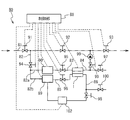
以下、本発明の実施の形態に係る水電解システムに関して、添付図面を参照して説明する。図1は、本発明の実施の形態に係る水電解システムの構成を示すブロック図である。水電解システム80は、水供給部90、電解液供給部89、水電解装置1、制御部88、配管82〜86、バルブ94〜99、濃度調整部102を具備する。矢印は、水の流れる方向を示す。
Hereinafter, a water electrolysis system according to an embodiment of the present invention will be described with reference to the accompanying drawings. FIG. 1 is a block diagram showing a configuration of a water electrolysis system according to an embodiment of the present invention. The
本発明では、水を電気分解で処理する水電解装置1に、水だけでなく電解液を供給して電気的処理の劣化現象を抑制する。水電解装置1における電解液の詳細、その供給方法及びその役割については、後述する。以下、本実施の形態について詳細に説明する。
In the present invention, not only water but also an electrolytic solution is supplied to the
水供給部90は、配管82aを介して供給された水(例示:水道水、以下同じ)の不純物を除去し、配管83(及びバルブ95)を介して水電解装置1へ供給する。水供給部90は、例えば、イオン交換樹脂フィルタ(図示されず)を含み、そのイオン交換により不純物を除去する。不純物としては、水電解装置1のセル(後述)の行う水の電気分解処理に対して影響を及ぼす物質である。そのような物質としては、カルシウム、マグネシウム等のミネラル分が例示される。イオン交換樹脂フィルタは、陽イオン交換樹脂(塩型:例示、Na型)に例示される。更に、これに加えて、塩素を除去するために、活性炭フィルタや亜硫酸カルシュウムのフィルタ、陰イオン交換樹脂フィルタの少なくとも一つを有していても良い。又は、水に含まれる他物質を可能な限り除去する装置を更に付加しても良い。
The water supply unit 90 removes impurities from water (eg, tap water, the same applies hereinafter) supplied via the
電解液供給部89は、配管82bを介して供給された水を用いて電解液を生成し、配管85(及びバルブ96)を介して水電解装置1へ供給する。電解液供給部89は、例えば、供給された水に、予めタンク等に貯蔵された電解質材料又は高濃度の電解液を所定の量だけ添加する方法などで電解液を生成する。電解液の詳細については後述する。なお、タンク等は外部の別の場所に設けても良い。また、高濃度の電解液を所定の量だけ添加する箇所は、電解液供給部89以外でもよく、例えば、水電解装置1内において、陰極とイオン導電膜(後述)との間に供給しても良い。
The electrolytic
濃度調整部102は、水電解装置1で使用された電解液を再利用するとき、使用済みの電解液のイオン濃度を調整し、電解液供給部89へ供給する。それにより、電解液供給部89−配管85(バルブ96)−水電解装置1−配管86(バルブ98)−濃度調整部102−電解液供給部89の循環路を用いて、電解液を循環させて再利用することができる。濃度調整部102は、塩素イオン濃度や、水素イオン濃度や、陽イオン濃度などを調整する。例えば、塩素イオン等の特定のアニオンを吸着させたアニオン交換樹脂や、水素イオンやナトリウムイオン等の特定のカチオンを吸着させたカチオン交換樹脂を備えている。それにより、電解液の組成変化を緩和し、電解液の交換頻度を低減できる。
When the electrolytic solution used in the
電解液を循環させて用いる場合、電解液供給部89が水電解装置1に供給する電解液の量は、水供給部90が水電解装置1に供給する水の量に対して、1/1000以上であることが好ましい。上限は特にないが、コストの面から例えば1/1以下である。例えば、水電解装置1の陽極側から送出される電解処理済みの水の量が1000Lのとき、陰極側の電解液は1L以上である。すなわち、同質(例示:同イオン濃度)のフレッシュな電解液を1L以上準備して用いることが好ましい。これは、後述されるように、電解効率を高めるために、電解液の塩素イオン濃度を所定の範囲に保つ必要が有るためである。
When the electrolytic solution is circulated and used, the amount of the electrolytic solution that the electrolytic
水電解装置1は、水供給部90から配管83を介して水を陽極側に、電解液供給部89から配管85を介して電解液を陰極側に、それぞれ供給される。そして、水に電力を印加する電気的処理(電気分解)を実行する。この電気分解で水分子が分解される。それにより、水に印加する電力の大きさに対応した生成物が生成する。例えば、通常の電気分解で用いられる電力(電圧、電流)を用いれば、陽極側で酸素ガスが、陰極側で水素ガスがそれぞれ生成される。一方、通常の電気分解で用いられる電力よりも高い電力(高い電圧、電流)を用いれば、陽極側でラジカル分子を豊富に含むラジカル酸素水が生成される。ラジカル分子は、活性酸素、過酸化水素、オゾン、ヒドロキシルラジカルに例示される。また、陰極側では水素ガス、又は水素ラジカルが生成される。水電解装置1は、陽極側の生成物を含む水を配管84に、陰極側の生成物を含む電解液を配管86にそれぞれ排出する。
In the
配管81は、水(例示:水道水)を供給する。バルブ91は、配管81の途中に設けられ、配管81の水の流通を制御する。バルブ92とバルブ93は、配管81の途中に設けられ、水電解システム80をバイパスする水の流通を制御する。配管82は、バルブ91とバルブ92との間の配管81から分岐し、バルブ94に接続されている。バルブ94は、水電解システム80への水の供給を制御する。配管82aは、バルブ94と水供給部90との間を接続している。配管82bは、バルブ94と電解液供給部89との間を接続している。配管83はバルブ95を介して、水供給部90と水電解装置1(陽極側)とを接続している。配管85はバルブ96を介して、電解液供給部89と水電解装置1(陰極側)とを接続している。配管84は、水電解装置1(陽極側)に接続され、バルブ97を介して(陽極側の)水を排水可能であり、また、バルブ99及び逆止弁を介して配管81へ水を排出可能である。配管86は、水電解装置1(陰極側)に接続され、バルブ100を介して(陰極側の)電解液を排出可能であり、また、バルブ98を介して濃度調整部102へ電解液を循環可能である。
The pipe 81 supplies water (for example, tap water). The valve 91 is provided in the middle of the pipe 81 and controls the flow of water in the pipe 81. The
制御部88は、バルブ91〜100、水供給部90、電解液供給部89、濃度調整部102及び水電解装置1の動作を制御する。ただし、全てを制御部88で制御しなくても良く、複数の制御装置で制御しても良い。また、制御部88を設けず、全て手動で制御することも可能である。制御部88はパーソナルコンピュータやマイクロコンピュータに例示される。
The
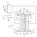
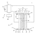
水電解装置1について更に説明する。図2は、本発明の実施の形態に係る水電解装置の構成を示す概略断面図である。水電解装置1は、電源部1bと、水電解装置本体1aとを備える。電源部1bの動作は、制御部88に制御されている。矢印は、水や電解液等の流れる方向を示す。ここでは、通常の電気分解ではなく、ラジカル酸素水を生成する電気分解を行う水電解装置について説明する。ただし、印加する電力を低く変更すれば、通常の電気分解用の水電解装置になる。
The
電源部1bは、水電解装置本体1aに電力を供給する。電源部1bは、交流電源32及び変換部31を含む。交流電源32は、所定の交流電力を供給する。交流電源32は、系統電源(電力会社が保有する商用の配電線網から供給される電源、例示:100V又は200V)に例示される。変換部31は、交流電源32から交流電力を供給され、所定の直流電力へ変換する。そして、その直流電力を水電解装置本体1aへ供給する。供給される直流電力は、例えば、電圧:4〜20V、水電解装置本体1aのセルの単位面積あたりの電流:0.1〜5A/cm2である。この電圧及び電流は通常の水の電気分解の直流電力よりも大きいため、陽極での反応によりオゾンや活性酸素が生成し易くなる。従って、この場合、水電解装置1はラジカル酸素水を生成する。
The
水電解装置本体1aは、水供給部90で処理された水21を陽極側に、電解液供給部89で処理された電解液23を陰極側に、それぞれ供給される。そして、電源部1bから供給される電力で、水21を電気的に処理(電気分解)して、ラジカル酸素水22として、外部に送出する。電解液23は循環させて再利用する。水電解装置本体1aは、陽極側流路2、陰極側流路3、セル13を備える。セル13は、イオン伝導膜10、陽極部11、陰極部12を含む。
In the water electrolysis apparatus
陽極側流路2は、開口部2a、流路2b、2c、2d、開口部2eを有する。開口部2aは、水電解装置本体1aの外表面に設けられ、配管83に接続されている。水供給部90で処理された水21を水電解装置本体1aへ導入する。流路2bは、開口部2aから水電解装置本体1aの内部の陽極部11の端部に向かって設けられている。開口部2aを介して供給された水21を陽極部11へ供給する。流路2cは、陽極部11の陽極4及びTi金網5(後述)の内部の隙間部分である。すなわち、供給された水21は、流路2cとしての陽極4及びTi金網5の内部の隙間部分を流通する。ただし、陽極4とイオン伝導膜10とは接触している部分と接触していない部分とが混在している。流路2dは、陽極部11の端部から水電解装置本体1aの外表面に向かって設けられている。陽極部11で処理されたラジカル酸素水22を開口部2eへ送出する。開口部2eは、水電解装置本体1aの外表面に設けられ、配管84に接続されている。流路2dからの水22を水電解装置本体1aから送出する。
The anode side flow path 2 has an
陰極側流路3は、開口部3a、流路3b、3c、3d、開口部3eを有する。開口部3aは、水電解装置本体1aの外表面に設けられ、配管85に接続されている。電解液供給部89で処理された電解液23を水電解装置本体1aへ導入する。流路3bは、開口部3aから水電解装置本体1aの内部の陰極部12の端部に向かって設けられている。開口部3aを介して供給された電解液23を陰極部12へ供給する。流路3cは、陰極部12の陰極8とイオン伝導膜10(後述)との間に設けられた隙間(一部、陰極8の内部の隙間部分を含む)である。すなわち、供給された電解液23は、流路3cとしての陰極8とイオン伝導膜10との間の隙間を流通する。ただし、陰極8とイオン伝導膜10とは、接触している部分がなく、互いに全く接触していない。流路3dは、陰極部12の端部から水電解装置本体1aの外表面に向かって設けられている。流路3cを通過した電解液24を開口部3eへ送出する。開口部3eは、水電解装置本体1aの外表面に設けられ、配管86に接続されている。流路3dからの電解液24を水電解装置本体1aから送出する。
The cathode side flow path 3 has an
セル13は、水電解装置本体1a内に設けられ、イオン伝導膜10、陽極部11、陰極部12を含んでいる。水供給部90から供給された水21が陽極側流路2を介して陽極部11に、電解液供給部89から供給された電解液23が陰極側流路3を介して陰極部12に、それぞれ供給される。セル13は、電源部1bから陽極部11と陰極部12とに供給される直流電力で、陽極部12内の水21を電気的に処理して、ラジカル酸素水22を生成する。
The
イオン導電膜(固体電解質膜)10は、陽極側の第1面10aと陰極側の第2面10bを有するプロトン導電膜(H型のイオン交換膜)である。プロトン導電膜としては、固体高分子膜のスルフォン酸型の強酸性陽イオン交換樹脂や、パーフルオロスルホン酸ポリマー膜に例示される。例えば、ナフィオン膜(登録商標:デュポン社製)に例示される。膜厚は、例えば、0.2mmである。
The ion conductive film (solid electrolyte membrane) 10 is a proton conductive film (H-type ion exchange membrane) having a
陽極部11は、イオン導電膜10の一方の面10aに接するように設けられ、水21が流通可能である。陽極部11は、電源部1bから直流電力を供給される電極として機能する。陽極部11は、第1電極部6、第2電極部5及び陽極4とを含む。第1電極部6は、変換部31が直流電力をセル13へ供給するとき、変換部31の正極に接続されている。第1電極部6は、導電性の板であり、Ti(チタン)板に例示される。第2電極部5は、一方の面を第1電極部6に密着し、他方の面を陽極4に密着するように設けられている。第2電極部5は、水21が透過可能な導電性の多孔体又は網であり、Ti(チタン)金網に例示される。金網は、例えば、0.4〜0.6mmφ、40メッシュである。陽極4は、一方の面を第2電極部5に密着し、他方の面をイオン伝導膜10の一方の面10aに密着するように設けられている。陽極4は、水21が透過可能で導電性があり、電解反応の触媒機能を有する多孔体又は網であり、Pt(白金)金網に例示される。金網は、例えば、0.05〜0.1mmφ、80メッシュである。
The
陰極部12は、イオン導電膜10の他方の面10bから離れて(接しないように)設けられている。供給される電解液23は、陰極部12とイオン導電膜10との間(隙間)である流路3cを流通可能である。陰極部12は、電極部9と陰極8とを含む。電極部9は、変換部31が直流電力をセル13へ供給するとき、変換部31の負極に接続されている。電極部9は、導電性の板であり、Ti(チタン)板に例示される。陰極8は、一方の面を電極部9に密着し、他方の面をイオン伝導膜10の他方の面10bから離れて設けられている。供給される電解液23は、陰極8とイオン導電膜10との間(隙間)である流路3cを流通可能である。陰極8は、電解液23が透過可能で導電性があり、電解反応の触媒機能を有する多孔体又は網であり、Pt(白金)金網に例示される。金網は、例えば、0.05〜0.1mmφ、80メッシュである。
The
第2電極部5として金網(例示:Ti金網)を用い、陽極4として金網(例示:Pt金網)を用いた場合、Ti金網とPt金網とが重なり狭隘な水路(以下、「マイクロ流路」ともいう)を形成している。そのため、第2電極部5及び陽極4とイオン伝導膜10との接触部分である金網中を、供給された水21が高速で通過するとき、流れが乱された状態となる。
When a wire mesh (example: Ti wire mesh) is used as the
一方、陰極8として金網(例示:Pt金網)を用いた場合、Pt金網が狭隘な流路を形成している。そのため、供給された電解液23は、金網中及びイオン伝導膜10と陰極8との隙間(流路3c)に充填された状態となる。
On the other hand, when a wire mesh (example: Pt wire mesh) is used as the
このような陽極部11と陰極部12の状態において、それら陽極部11と陰極部12との間に電力を供給して起こす電解によって、陽極側でオゾン等(気泡)が生成される。その場合、電解で生成された気泡は、流れが乱された水流と共にそのマイクロ流路を高速で通過する。そのため、気泡がそのマイクロ流路の幅以下の非常に細かい大きさになり、気液接触面積が増加すると考えられる。その結果、気泡は効率良く水中へ溶け込むことができる。すなわち、供給された水21は、陽極4の近傍を通過する際に効率的に電解され、オゾンや酸素が溶存したラジカル酸素水22となって送出される。それにより、水電解装置1で発生するラジカル酸素水22のオゾン等の濃度を高めることができる。
In such a state of the
電解液23としては、必ず塩素イオンを含んでいる溶液を用いる。例えば、水を溶媒とした場合、塩素を含むアルカリ金属塩を溶解させた水溶液や、水で希釈した塩酸である。塩素を含むアルカリ金属塩としては、塩化ナトリウム、塩化カリウム、塩化リチウムが例示される。また、他の塩化物を何らかの溶媒に溶解して使用することも効果的である。電解液23の詳細は後述される。
As the
陰極8とイオン伝導膜10との距離dは、大きければ大きいほどイオン伝導膜10の劣化が少なくなる。しかし、逆に大きすぎると電解液23の伝導度の限界によって電力損失が増大してしまう。従って、下限としては、劣化防止等の効果を考慮して、少なくともイオン伝導膜10の陰極側と陽極側との間で生じる電位差ΔVの1/10の電位差が生じる距離が好ましい。一方、上限としては、電解液の伝導度の限界を考慮して、電位差ΔVの4倍の電位差が生じる距離が好ましい。
As the distance d between the
電解液として例えば塩化ナトリウム水溶液を用いる場合、陰極8とイオン伝導膜10との距離dは以下のようになる。電解液23が10重量%の塩化ナトリウム水溶液であれば、その導電率は121mS/cmである。この値は、例えば、ナフィオン等のイオン伝導膜10の導電率とほぼ同等である。そのため、この程度の濃度の電解液23を使用する場合、イオン伝導膜10と陰極8との距離dはイオン伝導膜10の膜厚の0.1〜4倍とすることができる。すなわち、イオン伝導膜10の膜厚を0.2mmとすれば、イオン伝導膜10と陰極8との距離dは0.02mmから0.8mmとなる。
For example, when a sodium chloride aqueous solution is used as the electrolytic solution, the distance d between the
陰極8とイオン伝導膜10との間に隙間(流路3c)を設ける方法としては、例えば、陽極部11とイオン伝導膜10とを一体的に水電解装置本体1aの筐体に保持させる一方、陰極部12をイオン伝導膜10から離して水電解装置本体1aの筐体に保持させることが考えられる。また、陰極8とイオン伝導膜10との間は、例えば、陰極側の電解液23に陽極側の水21よりも高い圧力をかけることで、イオン伝導膜10と陽極4との密着性を確保すると共に、イオン伝導膜10と陰極8との距離dを一定に保つような構成にすることもできる。
As a method for providing a gap (flow
次に、電解液23について詳細に説明する。
既述のように、発明者は、電解中に陽極の表面に形成される酸化物(例えば白金の場合、PtOやPtO2)が電解能率の低下に大きく関与することを今回初めて見出した。すなわち、電解を行っていく過程で酸化物層が増大することで、陽極の電気抵抗の増大を引き起こしている。また、触媒能力が低い酸化層が増加することにより、陽極での反応効率の低下を招いている。更に、長時間の電解の場合、酸化層が多孔質になり、酸化層自身の電気抵抗も更に増加し、陽極と電解質膜との接触が阻害されて接触抵抗の増加が起きている。
Next, the
As described above, the inventor has found for the first time that an oxide (for example, PtO or PtO 2 in the case of platinum) formed on the surface of the anode during electrolysis greatly contributes to a decrease in electrolytic efficiency. That is, the increase in the oxide layer in the process of electrolysis causes an increase in the electrical resistance of the anode. In addition, an increase in the number of oxide layers having a low catalytic ability leads to a decrease in reaction efficiency at the anode. Furthermore, in the case of electrolysis for a long time, the oxide layer becomes porous, the electric resistance of the oxide layer itself further increases, the contact between the anode and the electrolyte membrane is inhibited, and the contact resistance increases.
発明者は、陰極側の電解液に塩素イオンを一定濃度以上溶解させることで、陽極の表面での酸化層の形成を著しく抑制することが可能であることを今回始めて見出した。酸化層の形成の抑制は、以下のメカニズムによると考えられる。すなわち、一定濃度以上の塩素イオンが電解液に溶解していることにより、電解質膜(イオン伝導膜10)を透過して陽極側に塩素イオンが到達し、陽極4と電解質膜(イオン伝導膜10)との界面に集中して存在することになる。その塩素イオンによって陽極表面での酸化が阻害され、陽極表面はフレッシュな状態な状態で保たれる。その結果、電解能率及び電極寿命を向上させることができる。この効果は電解液中の塩素イオンの濃度が高いほど強いと期待される。
The inventor found for the first time that the formation of an oxide layer on the surface of the anode can be remarkably suppressed by dissolving chlorine ions in the electrolyte solution on the cathode side at a certain concentration or more. The suppression of the formation of the oxide layer is considered to be due to the following mechanism. That is, when chlorine ions of a certain concentration or more are dissolved in the electrolytic solution, the chlorine ions pass through the electrolyte membrane (ion conductive film 10) and reach the anode side, and the
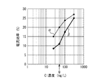
次に、電解液中の塩素イオンの濃度と、電解能率との関係について行った実験結果について説明する。図3Aは、電解液中の塩素濃度と電流効率との関係を示すグラフである。横軸は、電解液23に含まれる塩素(Cl)濃度(mg/L)を示している。すなわち、溶媒を水としてNaClを溶解させた電解液中の塩素濃度を示している。この場合、塩素濃度は、飽和濃度以下であり、実質的に塩素イオン(Cl−)濃度とみなすことができる。一方、縦軸は、陽極でのオゾンの生成量に基づいて算出した電流効率(%)を示している。すなわち、供給された電流に対するオゾン生成に使用された電流の割合を示している。この場合、電流効率(%)は、電解能率(電解効率)の一つの指標とみなすことができる。三角(曲線I)、四角(曲線II)、及び菱形(曲線III)は、セル13に供給される電流の電流密度がそれぞれ1A/cm2、0.75A/cm2、及び0.5A/cm2の場合を示している。本実験は、図1及び図2で説明した水電解システム80を用いて行った。
Next, the results of experiments conducted on the relationship between the concentration of chlorine ions in the electrolytic solution and the electrolytic efficiency will be described. FIG. 3A is a graph showing the relationship between the chlorine concentration in the electrolyte and the current efficiency. The horizontal axis indicates the chlorine (Cl) concentration (mg / L) contained in the
図3Aを参照すると、塩素濃度を塩素イオン(Cl−)濃度とみなせば、電流密度に拘わらず、電流効率は塩素イオン濃度に対して単調に増加していることが分かる。そして、塩素イオン濃度が35.5mg/L(0.001mol/L)の場合と比較して、50mg/L(0.0014mol/L:図3AのP)又はそれ以上の塩素イオン濃度であれば、電流効率が向上して、十分な効果が得られることが分かった。更に、塩素イオン濃度が100mg/L(0.0028mol/L)以上あることが好ましい。更に、塩素イオン濃度が177.5mg/L(0.005mol/L)以上あることがより好ましい。一方、塩素イオン濃度は多いほどよいので上限は特にない。ただし、溶媒を水としてNaClを溶解させた電解液の場合、NaClの飽和濃度(溶解度)で決まる。その場合、例えば、室温(例示:30℃)で約218g/Lである。 Referring to FIG. 3A, when the chlorine concentration is regarded as the chlorine ion (Cl − ) concentration, it can be seen that the current efficiency monotonously increases with respect to the chlorine ion concentration regardless of the current density. If the chlorine ion concentration is 50 mg / L (0.0014 mol / L: P in FIG. 3A) or higher than the case where the chlorine ion concentration is 35.5 mg / L (0.001 mol / L), It was found that the current efficiency was improved and a sufficient effect was obtained. Further, the chlorine ion concentration is preferably 100 mg / L (0.0028 mol / L) or more. Furthermore, the chlorine ion concentration is more preferably 177.5 mg / L (0.005 mol / L) or more. On the other hand, the higher the chlorine ion concentration, the better. However, in the case of an electrolytic solution in which NaCl is dissolved using water as a solvent, it is determined by the saturated concentration (solubility) of NaCl. In that case, for example, it is about 218 g / L at room temperature (example: 30 ° C.).
また、塩素イオン濃度が十分に高く、17750mg/L(0.5mol/L)又はそれ以上であれば、電流密度に拘わらず、概ね電流効率28%以上という効果が得られることが判明した。従って、電流効率28%程度で十分である場合には、この近傍の濃度、例えば、17.750g/L(0.5mol/L)〜71.000g/L(2.0mol/L)あれば、ある程度の効果を得ることは可能であると考えられる。 Further, it has been found that if the chlorine ion concentration is sufficiently high, 17,750 mg / L (0.5 mol / L) or more, the effect of approximately 28% current efficiency can be obtained regardless of the current density. Therefore, when a current efficiency of about 28% is sufficient, a concentration in the vicinity thereof, for example, 17.750 g / L (0.5 mol / L) to 71.000 g / L (2.0 mol / L), It is considered possible to obtain a certain effect.
塩素イオンによる酸化防止効果が起きるのは、広い電位範囲で陽極表面にCl−イオンの被覆が発生するためであると考えられる。そのCl−イオンの被膜は、陽極表面に酸素が到達することを妨げ、結果として表面の酸化層形成を防止する。また、陽極表面に酸化層が形成されたとしても、Cl−イオンの存在下では、その酸化層が塩化物(例示:PtCl4)に変化して水中に溶出するため、陽極表面に酸化層が蓄積されることが少ないことも判明した。 The reason that the antioxidant effect by chlorine ions occurs is considered to be that Cl − ions are coated on the anode surface in a wide potential range. The Cl − ion coating prevents oxygen from reaching the anode surface and consequently prevents the formation of an oxide layer on the surface. Even if an oxide layer is formed on the anode surface, in the presence of Cl − ions, the oxide layer changes into chloride (eg, PtCl 4 ) and elutes in water. It was also found that there was little accumulation.
また、発明者の実験から、電解液23は塩素イオン以外のハロゲンイオン(例示:F−、Br−、I−)をできるだけ含まないことが好ましいことが判明した。上記効果を奏するのが塩素イオンであること、他のハロゲンイオンはその効果を奏さず、塩素イオンの効果を阻害する可能性が有ることなどの理由による。具体的には、ハロゲンイオンは10mg/L(例示:F−、Br−、I−=0.53、0.13、0.08×10−3mol/L)以下にすることが好ましい。更に、1mg/L(例示:0.053、0.013、0.008×10−3mol/L)以下にすることがより好ましい。
Further, from the inventors' experiments, it has been found that the
これら塩素イオンの効果は、陽極に供給される水の中に塩素イオンが存在している場合よりも、陰極に供給される電解液の中に存在している場合の方が顕著である。発明者の実験によれば、例えば、陽極側にNaCl:0.001mol/L水溶液を用い、電流密度0.5A/cm2のときの陽極でのオゾン発生量は約0.55mg/Lであったのに対して、陰極側にNaCl:0.001mol/L水溶液を用い、電流密度0.5A/cm2のときの陽極でのオゾン発生量は約7.9mg/Lであった。すなわち、陰極側に塩素イオンを混入した方が、10倍以上効果が有ることが分かった。これは、陰極側の電解液のCl−イオンは、電解質膜中を電位差によって泳動して陽極の表面に集中的に供給されるが、陽極側の水にCl−イオンが存在しても、陰極側のCl−イオンのような作用が殆ど現れないためである。したがって、陰極溶液中に塩素イオンが存在することが極めて重要である。
The effect of these chlorine ions is more remarkable when the chlorine ions are present in the electrolytic solution supplied to the cathode than when the chlorine ions are present in the water supplied to the anode. According to the inventor's experiment, for example, an aqueous solution of NaCl: 0.001 mol / L was used on the anode side, and the amount of ozone generated at the anode at a current density of 0.5 A / cm 2 was about 0.55 mg / L. In contrast, the amount of ozone generated at the anode when the NaCl: 0.001 mol / L aqueous solution was used on the cathode side and the current density was 0.5 A / cm 2 was about 7.9 mg / L. That is, it has been found that mixing chlorine ions on the cathode side has an
ここで、陽極表面にCl−イオンが集中すると生成物に次亜塩素酸イオンが生成する可能性が考え得る。しかし、電解による次亜塩素酸の反応生成速度は遅い。そのため、図1及び図2の構造の水電解装置1のセル13において陽極部11内での水の流通速度を大きくすることで、次亜塩素酸が生成する前に水をセル13外に排出することができる。水の流通速度を大きくすることは、水がセル13内に滞留する時間を短くすることに対応する。従って、滞留時間は短いほど、次亜塩素酸の生成が少なくなり、好ましいことが分かる。その滞留時間の好ましい範囲は、使用している装置やその使用条件等により異なる。発明者による研究によれば、通常使用条件(例示:印加電圧:4〜20V、電流密度:0.1〜5A/cm2、電解液の塩素イオン濃度:50mg/L〜218g/L)下では、セル13内の水の滞留時間を10秒以下にすれば次亜塩素酸イオンの発生を抑制でき、更にセル13内の水の滞留時間を1秒以下にすれば次亜塩素酸イオンの発生を大幅に抑制できることが分かった。それは以下の理由による。
Here, if Cl − ions concentrate on the anode surface, hypochlorite ions may be generated in the product. However, the reaction generation rate of hypochlorous acid by electrolysis is slow. Therefore, by increasing the flow rate of water in the
電解による次亜塩素酸の生成速度は、電流密度に比例する。そして、上記セル13の通常使用条件での電流密度で、40mg/Ahの次亜塩素酸イオンが生成する。これを、上記セル13に当てはめて考えると、セル13の上記通常使用条件の電流密度で、10秒程度の滞留時間とすることで、次亜塩素酸は1mg程度の生成量になると見積もられる。これは、1mg/L程度の次亜塩素酸濃度であり、生成されるオゾンの濃度を大幅に下回る。すなわち、オゾンと比較して次亜塩素酸が効果を表す濃度ではない。しかしながら、滞留時間が長くなると次亜塩素酸の生成が無視できなくなるので、セル13内に流れる電解水の滞留時間は1秒以下がより好ましい。更に、0.5秒以下とすることが好ましく、0.1秒以下とすることが更により好ましい。
The rate of formation of hypochlorous acid by electrolysis is proportional to the current density. And 40 mg / Ah hypochlorite ion is produced | generated by the current density on the normal use conditions of the said
更に、陽極部11内での水の流通速度を大きくし、陽極部11内での水の滞留時間を短くすることで、陽極部11側で生成するイオン種や気泡を速く流し出してフレッシュな水を供給することができる。その結果、水電解装置1におけるラジカル酸素水22の生成効率を高めることができる。
Further, by increasing the flow rate of water in the
また、電解液23には、電気伝導度を向上させるために、他の電解質材料を加えても良い。例えば、硝酸イオンや硫酸イオンを生じさせるような材料である。そのような材料として、硝酸、硫酸、硝酸ナトリウム、又は硫酸ナトリウムが例示される。
In addition, another electrolyte material may be added to the
更に、電解液23のpHを安定化させるために、電解液23を緩衝溶液としても良い。例えば、NaClの水溶液に、ホウ酸+ホウ酸ナトリウム、リン酸+リン酸ナトリウム、酢酸+酢酸ナトリウム、又はクエン酸+クエン酸ナトリウムなどを加えることで、電解液23を緩衝溶液とすることができる。
Furthermore, in order to stabilize the pH of the
次に、電解液中の塩素イオンの濃度と、電解能率との関係について行った他の実験結果について説明する。この実験では、電解を長時間行った場合の影響について調べている。図3Bは、電解液中の塩素濃度と電流効率との関係を示すグラフである。この場合にも、横軸は、電解液23に含まれる塩素(Cl)濃度(mg/L)を示している。すなわち、溶媒を水としてNaClを溶解させた電解液中の塩素濃度を示している。この場合、塩素濃度は、飽和濃度以下であり、実質的に塩素イオン(Cl−)濃度とみなすことができる。また、縦軸は、陽極でのオゾンの生成量に基づいて算出した電流効率(%)を示している。すなわち、供給された電流に対するオゾン生成に使用された電流の割合を示している。この場合、電流効率(%)は、電解能率(電解効率)の一つの指標とみなすことができる。菱形(曲線α)は電解開始後1時間以内(初期状態)の電流効率を示し、丸(曲線β)は電解開始後20時間連続運転後の電流効率を示している。ただし、電流密度は、いずれも0.625A/cm2の場合を示している。本実験は、図1及び図2で説明した水電解システム80を用いて行った。
Next, the results of another experiment conducted on the relationship between the concentration of chlorine ions in the electrolytic solution and the electrolytic efficiency will be described. In this experiment, the effect of performing electrolysis for a long time is examined. FIG. 3B is a graph showing the relationship between the chlorine concentration in the electrolytic solution and the current efficiency. Also in this case, the horizontal axis indicates the chlorine (Cl) concentration (mg / L) contained in the
図3Bを参照すると、塩素濃度を塩素イオン(Cl−)濃度とみなせば、塩素イオン濃度が100mg/L以下になると、初期状態の電流効率も大きく低下するが、20時間運転後の電流効率は更に低下が大きい。実用的には、電流効率が10%以上あることが好ましいことから、長時間の運転に際して少なくとも50mg/L(0.0014mol/L:図3BのQ)又はそれ以上の塩素イオン濃度が必要であることが分かる。 Referring to FIG. 3B, assuming that the chlorine concentration is the chlorine ion (Cl − ) concentration, the current efficiency in the initial state is greatly reduced when the chlorine ion concentration becomes 100 mg / L or less, but the current efficiency after 20 hours of operation is Furthermore, the decrease is great. Practically, since the current efficiency is preferably 10% or more, a chlorine ion concentration of at least 50 mg / L (0.0014 mol / L: Q in FIG. 3B) or more is required for a long-time operation. I understand that.
上述されたように、電解液23中の塩素イオン濃度が低い場合、陽極の表面に酸化膜が生成して行くことでオゾン発生を阻害するようになり、電流効率が低下する。しかし、電解液23中の塩素イオン濃度が十分に高い場合、陽極表面の酸化物は塩素によって溶かされるため、陽極表面に酸化膜が生成することを抑制することができる。そして、その効果は、電解の時間が長くなればなるほど顕著になることが分かる。このデータからも、電解液23の塩素イオン濃度は50mg/Lは最低でも必要であり、好ましくは100mg/L以上は必要であることが分かる。
As described above, when the chlorine ion concentration in the
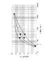
次に、セルに流す電流密度と、電解能率との関係について行った実験結果について説明する。図4は、電流密度と電流効率との関係を示すグラフである。横軸は、セル13に流れる電流の電流密度(A/cm2)を示している。一方、縦軸は、陽極でのオゾンの生成量に基づいて算出した電流効率(%)を示している。この場合、電流効率(%)は、電解能率の一つの指標とみなすことができる。菱形(曲線A)、四角(曲線B)、及び三角(曲線C)は、陰極8に供給される電解液23の塩素イオン濃度(塩素濃度)がそれぞれ0.5mol/L、0.01mol/L、及び0.005mol/Lの場合を示している。本実験は、図1及び図2で説明した水電解システム80を用いて行った。
Next, the experimental results of the relationship between the current density flowing through the cell and the electrolytic efficiency will be described. FIG. 4 is a graph showing the relationship between current density and current efficiency. The horizontal axis indicates the current density (A / cm 2 ) of the current flowing through the
図4を参照すると、電流密度が高くなるほど電流効率が向上するが、電流密度がある程度の値になると電流効率は飽和することが分かった。例えば、0.5mol/L(曲線A)の場合、0.5A/cm2以上になると、電流効率は約28%で概ね飽和していることが分かる。0.01mol/L(曲線B)及び0.005mol/L(曲線C)の場合にも、グラフは完全には飽和していないが、電流密度を高めることで、飽和しつつあることが見て取れる。また、塩素イオン濃度(塩素濃度)が高いほど、低い電流密度で電流効率が飽和することが分かる。したがって、塩素イオン濃度を高めることにより、低い電流密度で十分な電流効率を得ることができることが裏付けられている。 Referring to FIG. 4, it was found that the current efficiency increases as the current density increases, but the current efficiency is saturated when the current density reaches a certain value. For example, in the case of 0.5 mol / L (curve A), it can be seen that when the current is 0.5 A / cm 2 or more, the current efficiency is approximately saturated at about 28%. Even in the case of 0.01 mol / L (curve B) and 0.005 mol / L (curve C), the graph is not completely saturated, but it can be seen that it is saturated by increasing the current density. It can also be seen that the higher the chlorine ion concentration (chlorine concentration), the more saturated the current efficiency at a lower current density. Therefore, it is supported that a sufficient current efficiency can be obtained at a low current density by increasing the chlorine ion concentration.
以上の図3Aと図3Bと図4の結果をまとめると、塩素イオン(Cl−)濃度が50mg/L(0.0014mol/L:図3AのP、図3BのQ)又はそれ以上であれば、電流効率が向上して、十分な効果が得られる。また、塩素イオン濃度が十分に高く、17750mg/L(0.5mol/L)又はそれ以上であれば、電流密度に拘わらず、概ね電流効率28%以上という効果が得られる。塩素イオン濃度の上限は特になく飽和濃度でも良い。ただし、電流効率28%程度で十分である場合には、この近傍の濃度、例えば、17.750g/L(0.5mol/L)〜71.000g/L(2.0mol/L)であればよい。また、より低い電流密度で十分な電流効率を得ようとする場合には、塩素イオン濃度を高めることで達成することができる。 When the results of FIGS. 3A, 3B, and 4 are summarized, the chlorine ion (Cl − ) concentration is 50 mg / L (0.0014 mol / L: P in FIG. 3A, Q in FIG. 3B) or more. The current efficiency is improved and a sufficient effect is obtained. In addition, if the chlorine ion concentration is sufficiently high and 17750 mg / L (0.5 mol / L) or more, the effect of current efficiency of 28% or more can be obtained regardless of the current density. There is no particular upper limit on the chlorine ion concentration, and a saturated concentration may be used. However, if a current efficiency of about 28% is sufficient, the concentration in this vicinity, for example, 17.750 g / L (0.5 mol / L) to 71.000 g / L (2.0 mol / L) may be used. Good. Moreover, when trying to obtain sufficient current efficiency at a lower current density, it can be achieved by increasing the chlorine ion concentration.
次に、本実施の形態に係る水電解装置の技術的効果について説明する。
本実施の形態では、陰極側の電解液23に塩素イオンを一定濃度(50mg/L)以上溶解させている。それにより、陽極4の表面での酸化層の形成を著しく抑制することができる。すなわち、一定濃度以上の塩素イオンが電解液23に溶解していることにより、イオン伝導膜10を透過して陽極側に塩素イオンが移動して、陽極4とイオン伝導膜10との界面に塩素イオンが集中して存在することになる。その結果、その塩素イオンによって陽極表面での酸化が阻害され、又は、酸化層が塩素化されて除去される。そのため、陽極表面はフレッシュな状態な状態で保つことができる。その結果、電解能率及び電極寿命を向上させることができる。
Next, technical effects of the water electrolysis apparatus according to the present embodiment will be described.
In the present embodiment, chlorine ions are dissolved in the
また、本実施の形態では、陰極8をイオン伝導膜10から離し、その間の流路3cに電解液23を満たしている。このような構造では、イオン伝導膜10内での電界集中は緩和され、電界はほぼ均一な状態になる。イオン伝導膜10中を移動するイオンの密度はほぼ均一となり、イオン伝導膜10での電圧ロスも最小限にすることができる。更に、電源の遮断(電源オフ)時には、陰極8の近傍の水素イオンは電解液23中のアニオンにトラップされる。そのため、その水素イオンはイオン伝導膜10中に移動することは無い。加えて、イオン伝導膜10中の水素イオンもイオン伝導膜10中にあるアニオンにトラップされる。そのため、陽極側に移動する水素イオンは非常に少なくなる。従って、陽極4が水素と反応することは大きく抑制されるため、陽極4の触媒活性は電源の遮断時でも維持される。
In the present embodiment, the
以上のような効果により、陽極4の劣化やイオン伝導膜10の劣化は最小限に抑えられると共に電極寿命や電界効率の向上を図ることができる。その結果、水電解システムの寿命及び効率は大幅に改善される。
Due to the above effects, the deterioration of the
次に、本発明の実施の形態に係る水電解システムの動作について説明する。ここでは、通常の電気分解ではなく、ラジカル酸素水を生成する電気分解を行う水電解システムについて説明する。ただし、印加する電力を低く変更すれば、通常の電気分解用の水電解システムになる。 Next, the operation of the water electrolysis system according to the embodiment of the present invention will be described. Here, a water electrolysis system that performs electrolysis to generate radical oxygen water instead of normal electrolysis will be described. However, if the applied power is changed to a low level, a normal electrolysis water electrolysis system is obtained.
図1を参照して、バルブ91、93、94、95、96、98、99は開いている。バルブ92は、水とラジカル酸素水とが所望の割合で混合されるのに必要な量の水を配管82へ流すような開度に開いている。
Referring to FIG. 1,
配管82、82aを流通した水道水が水供給部90へ供給される。水供給部90は、水電解装置1のセル13の行う水の電気的な処理に対して影響を及ぼす物質を水道水から除去する。水供給部90で処理された水21は、配管83を介して水電解装置1の陽極側へ供給される。一方、配管82、82bを流通した水道水が電解液供給部89へ供給される。電解液供給部89は、水道水を用いて電解液23を生成する。電解液供給部89で生成された電解液23は、配管85を介して水電解装置1の陰極側へ供給される。電解液23は、塩素イオンの濃度が50mg/L以上とし、他のハロゲンイオンの濃度は10mg/L以下とする。
The tap water flowing through the
図2を参照して、水供給部90で処理された水21が、水電解装置1の流路2bを流通して陽極部11へ供給される。水21は、第2電極部5及び陽極4の中を流通する。一方、電解液供給部89で生成された電解液23が、水電解装置1の流路3bを流通して陰極部12へ供給される。電解液23は、陰極8及び流路3cの中を流通する。電源部1bの変換部31は、陽極部11と陰極部12との間に所定の直流電圧を供給する。その結果、陰極8とイオン伝導膜10と陽極4との間で、電解反応が行われる。電解反応により、陽極側で、酸素ガスよりもオゾンや活性酸素が多く生成される。その結果、陽極側で、活性酸素、過酸化水素、オゾン及びヒドロキシルラジカルのようなラジカル分子を豊富に含むラジカル酸素水22が生成される。ラジカル酸素水22は、流路2dを介して水電解装置1の外部(配管84)へ送出される。また、陰極側では電解液中に水素が生成される。このとき、陽極側の水は滞留時間が1秒以下になるように流速が制御される。また、ラジカル酸素水22を1000L生成する場合、電解液23は少なくとも1L用いられる。例えば、陽極4に1000Lの水が供給される間に、陰極8に再利用されていない電解液23が少なくとも1L供給される。
With reference to FIG. 2, the
電解液23中の塩素イオンのごく一部は、電解質膜を透過して、陽極と電解質膜との界面に塩素イオンが移動する。それにより、陽極表面は塩素イオンで被覆され、酸化膜の形成が防止される。また、陽極表面に酸化層が形成されたとしても塩素イオンの存在下では、その酸化層が塩化物(例示:PtCl4)に変化して水中に溶出するため、陽極表面に酸化層が蓄積されることが少ない。また、陰極8をイオン伝導膜10から離し、その間の流路3cに電解液23を満たしているので、イオン伝導膜10内での電界集中は緩和され、電界はほぼ均一な状態になる。イオン伝導膜10中を移動するイオンの密度はほぼ均一となり、イオン伝導膜10での電圧ロスも最小限にすることができる。
A small part of the chlorine ions in the
図1を参照して、ラジカル酸素水22は、配管84及びバルブ99を介して、水供給部90及び水電解装置1をバイパスした配管81の水と混合される。そして、所望の濃度を有するラジカル酸素水22としてバルブ93から送出される。なお、ラジカル酸素水22を、配管81の水と混合せずに、バルブ97を介してそのまま使用することも可能である。一方、水電解装置1の陰極部12で使用された排電解液24は、配管86を介して濃度調整部102へ供給され、濃度調整をされた後、電解液供給部89へ循環、再利用される。ただし、バルブ100を介して外部へ排出しても良い。
Referring to FIG. 1,
その後の水電解装置1の電源の遮断(電源オフ)時には、陰極8の近傍の水素イオンは電解液23中のアニオンに、イオン伝導膜10中の水素イオンもイオン伝導膜10中にあるアニオンにそれぞれトラップされる。そのため、その水素イオンはほとんど移動しなくなる。陽極4が水素イオンと反応することは大きく抑制されるため、陽極4の触媒活性は電源の遮断時でも維持される。
Thereafter, when the power of the
以上のように、本発明の実施の形態に係る水電解システムは動作することができる。 As described above, the water electrolysis system according to the embodiment of the present invention can operate.
上記実施の形態では、陰極8とイオン伝導膜10との間には電解液23のみが存在している。しかし、本発明はその例に限定されるものではない。すなわち、陰極8とイオン伝導膜10との間に、電解液23を含んだ非導電性部材を有していても良い。図5は、本発明の実施の形態に係る水電解装置の他の構成を示す概略断面図である。この水電解装置1は、基本的には図2の水電解装置1と同じである。ただし、陰極8とイオン伝導膜10との間(流路3c)に非導電性部材7を有している点で、図2の場合と異なる。
In the above embodiment, only the
非導電性部材7は、陰極8とイオン伝導膜10との間(流路3c)に設けられ、非導電性の材料で形成されている。非導電性部材7は、電解液23を内部に流通可能であり、多孔体又は網状体に例示される。非導電性部材7は、例えば、ガラス繊維や石英繊維のような無機的材料や海綿や綿のような有機的材料を用いたスポンジ状のものなどを使用することができる。特に、ガラス繊維や石英繊維のような無機的材料物は、有機物と比較して液中で安定的で効果が高く好ましい。非導電性部材7は、また、弾性力のあるものが好ましい。その場合、陰極側の電解液23に、陽極側の水21よりも高い圧力をかけるのではなく、イオン伝導膜10と陰極8との間に弾性力を持った非導電性部材7を挟み、その非導電性部材7の弾性力でイオン伝導膜10を陽極4に押さえつける構造をとることが可能となる。
The
また、電解液23は非導電性部材7としてのスポンジや綿に含んだ状態で存在しても良いし、更に外側に電解液23を貯蔵したタンクを設け、ポンプで循環する構造としても良い。こうすることにより、電解液23の組成変化が少なくなるとともに、電解液23の補充や交換が容易になる。
Further, the
本実施の形態において、原料の水である水道水を用いて生成されたラジカル酸素水は、含有されるラジカル量は従来の技術では見られない程多く、例えば、約1017個/L以上である。そのため、原料の水である水道水に20%〜30%程度添加しても、その効果(例示:殺菌効果)が確認できる。従来型の電解水では希釈応用というような電解された水を薄めて応用する技術は、その性格上確認されていなかった。しかし、本発明のラジカル酸素水においては、上述の様に希釈応用の様な使用環境も可能となる。ただし、水で希釈した場合には、その希釈量に応じて本来の水に戻る作用も早くなる。本発明で生成されたラジカル酸素水は、中性領域を保つようにコントロールされている。 In the present embodiment, the radical oxygen water generated using tap water which is the raw material water contains a radical amount that is not found in the prior art, for example, about 10 17 / L or more. is there. Therefore, even if about 20% to 30% is added to tap water which is raw material water, the effect (example: sterilization effect) can be confirmed. In conventional electrolyzed water, a technique for diluting and applying electrolyzed water, such as dilution application, has not been confirmed due to its character. However, in the radical oxygen water of the present invention, a use environment such as dilution application is possible as described above. However, when diluted with water, the action of returning to the original water is accelerated according to the amount of dilution. The radical oxygen water produced in the present invention is controlled so as to maintain a neutral region.
本実施の形態の技術は、既述のように、通常の水の電気分解を行う電解装置に適用することができる。加えて、電気分解の正反対の反応である燃料電池の発電に対しても同様に適用することができる。すなわち、上記電気分解と正反対の反応を用いた固体高分子形燃料電池においても、本実施の形態の技術を適用することで、固体高分子形燃料電池においても発生している劣化現象を同様に抑制することができる。その場合、例えば、図2の水電解装置本体1aにおいて、陰極部12の側(流路3c)に酸化剤(例示:酸素)及び電解液を、陽極部11の側に燃料(例示:水素ガス+水)をそれぞれ供給し、必要に応じて所定の温度に加熱する。そうすると、陽極部11の水素ガスは水素イオンとなりイオン導電膜10中を陰極部12の側へ移動してくる。この場合、陰極部12が固体高分子形燃料電池のカソード部12(陰極8はカソード8)となり、陽極部11が固体高分子形燃料電池のアノード部11(陽極4はアノード4)となる。
As described above, the technique of the present embodiment can be applied to an electrolysis apparatus that performs electrolysis of normal water. In addition, the present invention can be similarly applied to power generation of a fuel cell that is a reaction opposite to electrolysis. That is, even in a polymer electrolyte fuel cell using the reaction opposite to the electrolysis described above, the deterioration phenomenon occurring in the polymer electrolyte fuel cell can be similarly applied by applying the technique of the present embodiment. Can be suppressed. In that case, for example, in the water electrolysis apparatus
本発明は上記実施の形態に限定されるものではなく、発明の範囲及び精神を逸脱しない変形や変更が可能であることは明らかである。 The present invention is not limited to the above-described embodiment, and it is obvious that modifications and changes can be made without departing from the scope and spirit of the invention.
1 水電解装置(1b 電源部 1a 水電解装置本体)
2 陽極側流路(2a、2e 開口部 2b、2c、2d 流路)
3 陰極側流路(3a、3e 開口部 3b、3c、3d 流路)
4 陽極(アノード)
5 第2電極部
6 第1電極部
7 非導電性部材
8 陰極(カソード)
9 電極部
10 イオン伝導膜(10a 第1面 10b 第2面)
11 陽極部(アノード部)
12 陰極部(カソード部)
13 セル
21 水(供給水)
22 ラジカル酸素水
23 電解液
24 排電解液
31 変換部
32 交流電源
80 水電解システム
81、82、82a、82b、83、84、85、86 配管
88 制御部
89 電解液供給部
90 水供給部
91、92、93、94、95、96、97、98、99、100 バルブ
102 濃度調整部
1 Water electrolysis device (1b
2 Anode-side flow path (2a, 2e
3 Cathode side flow path (3a, 3e
4 Anode
5
9
11 Anode (Anode)
12 Cathode part (cathode part)
13
22
Claims (14)
電解液を供給する電解液供給部と、
前記水と前記電解液とを供給され、前記水を電気分解する処理を実行し、前記処理後の前記水を送出する水電解装置と
を具備し、
前記水電解装置は、
第1の面と、前記第1の面と反対側の第2の面とを有する固体電解質膜と、
前記第1の面の側に、前記第1の面に接して設けられ、前記水が流通する陽極と、
前記第2の面の側に、前記第2の面から離れて設けられた陰極と、
前記陰極と前記第2の面との間に設けられ、前記電解液が流通する流路と
を備え、
前記電解液は、塩素イオンを含み、
前記塩素イオンの濃度は、50mg/L以上飽和濃度以下である
水電解システム。 A water supply section for supplying water;
An electrolyte supply unit for supplying the electrolyte;
A water electrolysis device that is supplied with the water and the electrolytic solution, performs a process of electrolyzing the water, and sends out the water after the treatment;
The water electrolysis device is:
A solid electrolyte membrane having a first surface and a second surface opposite to the first surface;
An anode provided on the first surface side in contact with the first surface and through which the water flows;
A cathode provided on the second surface side, apart from the second surface;
A passage provided between the cathode and the second surface and through which the electrolyte flows,
The electrolytic solution contains chlorine ions,
The concentration of the chlorine ions is 50 mg / L or more and a saturation concentration or less.
前記電解液は、前記塩素イオン以外のハロゲンイオンの濃度が10mg/L以下である
水電解システム。 The water electrolysis system according to claim 1,
The electrolytic solution is a water electrolysis system in which a concentration of halogen ions other than the chlorine ions is 10 mg / L or less.
前記陽極での前記水の滞留時間は、0秒より大きく10秒以下である
水電解システム。 The water electrolysis system according to claim 1 or 2,
The water electrolysis system wherein the residence time of the water at the anode is greater than 0 seconds and not more than 10 seconds.
前記塩素イオンは、アルカリ金属塩又は塩酸の塩素イオンを含む
水電解システム。 In the water electrolysis solution system according to any one of claims 1 to 3,
The chlorine ion is a water electrolysis system containing an alkali metal salt or a chloride ion of hydrochloric acid.
前記電解液は、電気伝導度を向上させる電解質材料を更に含む
水電解システム。 In the water electrolysis system according to any one of claims 1 to 4,
The electrolytic solution further includes an electrolyte material for improving electrical conductivity.
前記電解液は、緩衝溶液である
水電解システム。 The water electrolysis system according to any one of claims 1 to 5,
The electrolysis solution is a buffer solution.
前記電解液の塩素イオン濃度を調整する第1濃度調整部を更に具備する
水電解システム。 The water electrolysis system according to any one of claims 1 to 6,
A water electrolysis system further comprising a first concentration adjusting unit for adjusting a chlorine ion concentration of the electrolytic solution.
前記電解液の陽イオン濃度を調整する第2濃度調整部を更に具備する
水電解システム。 The water electrolysis system according to any one of claims 1 to 7,
A water electrolysis system further comprising a second concentration adjusting unit for adjusting a cation concentration of the electrolytic solution.
前記電解液供給部は、前記水電解装置から送出された前記電解液を受け入れ、受け入れた前記電解液を前記水電解装置に供給する
水電解システム。 The water electrolysis system according to claim 7 or 8,
The electrolytic solution supply unit is a water electrolysis system that receives the electrolytic solution sent from the water electrolytic device and supplies the received electrolytic solution to the water electrolytic device.
前記電解液供給部が前記水電解装置に供給する前記電解液の量は、前記水供給部が前記水電解装置に供給する前記水の量に対して、1/1000以上1/1以下である
水電解システム。 The water electrolysis system according to any one of claims 1 to 9,
The amount of the electrolytic solution supplied to the water electrolysis device by the electrolytic solution supply unit is 1/1000 or more and 1/1 or less with respect to the amount of water supplied from the water supply unit to the water electrolysis device. Water electrolysis system.
前記固体電解質膜の第2の面の側に前記第2の面から離れて設けられた陰極と、前記第2の面との間に電解液を流すステップと、
前記陽極と前記陰極との間に直流電力を印加するステップと
を具備し、
前記電解液は、塩素イオンを含み、
前記塩素イオンの濃度は、50mg/L以上飽和濃度以下である
水電解方法。 Flowing water through an anode provided in contact with the first surface of the solid electrolyte membrane and capable of flowing water;
Flowing an electrolytic solution between the second surface and a cathode provided on the second surface side of the solid electrolyte membrane away from the second surface;
Applying DC power between the anode and the cathode, and
The electrolytic solution contains chlorine ions,
The water electrolysis method, wherein the concentration of the chlorine ions is 50 mg / L or more and a saturation concentration or less.
前記電解液は、前記塩素イオン以外のハロゲンイオンの濃度が10mg/L以下である
水電解方法。 The water electrolysis method according to claim 11,
The electrolytic solution is a water electrolysis method wherein the concentration of halogen ions other than chlorine ions is 10 mg / L or less.
前記陽極での前記水の滞留時間は、0秒より大きく10秒以下である
水電解方法。 The water electrolysis method according to claim 11 or 12,
The water electrolysis method, wherein a residence time of the water at the anode is greater than 0 seconds and 10 seconds or less.
塩素を含むアルカリ金属塩又は塩酸の水溶液を電解液として準備するステップを更に具備する
水電解方法。 The water electrolysis method according to any one of claims 11 to 13,
A water electrolysis method further comprising the step of preparing an aqueous solution of an alkali metal salt containing hydrochloric acid or hydrochloric acid as an electrolytic solution.
Priority Applications (1)
| Application Number | Priority Date | Filing Date | Title |
|---|---|---|---|
| JP2011233910A JP2012107331A (en) | 2010-10-26 | 2011-10-25 | Water electrolysis system |
Applications Claiming Priority (3)
| Application Number | Priority Date | Filing Date | Title |
|---|---|---|---|
| JP2010240176 | 2010-10-26 | ||
| JP2010240176 | 2010-10-26 | ||
| JP2011233910A JP2012107331A (en) | 2010-10-26 | 2011-10-25 | Water electrolysis system |
Publications (1)
| Publication Number | Publication Date |
|---|---|
| JP2012107331A true JP2012107331A (en) | 2012-06-07 |
Family
ID=46493223
Family Applications (1)
| Application Number | Title | Priority Date | Filing Date |
|---|---|---|---|
| JP2011233910A Pending JP2012107331A (en) | 2010-10-26 | 2011-10-25 | Water electrolysis system |
Country Status (1)
| Country | Link |
|---|---|
| JP (1) | JP2012107331A (en) |
Cited By (6)
| Publication number | Priority date | Publication date | Assignee | Title |
|---|---|---|---|---|
| WO2015146944A1 (en) * | 2014-03-28 | 2015-10-01 | 国立大学法人横浜国立大学 | Device for manufacturing organic hydride |
| JP2015196871A (en) * | 2014-03-31 | 2015-11-09 | 石川金属機工株式会社 | Apparatus and method for production of radical oxygen water |
| JP2015196872A (en) * | 2014-03-31 | 2015-11-09 | 石川金属機工株式会社 | Apparatus and method for supply of radical oxygen water |
| JP2015196873A (en) * | 2014-03-31 | 2015-11-09 | 石川金属機工株式会社 | Apparatus and method for production of radical oxygen water |
| CN114314759A (en) * | 2021-12-15 | 2022-04-12 | 珠海格力电器股份有限公司 | Ozone water preparation system and preparation method thereof |
| JP7452842B2 (en) | 2020-03-03 | 2024-03-19 | 日本水力株式会社 | Hydrogen production system and hydrogen production method |
Citations (4)
| Publication number | Priority date | Publication date | Assignee | Title |
|---|---|---|---|---|
| JP2000001794A (en) * | 1998-06-15 | 2000-01-07 | Asahi Glass Co Ltd | Method for electrolyzing salt water |
| JP2001271098A (en) * | 2000-03-24 | 2001-10-02 | Lion Corp | Electrolytic cleaning water, method for producing the same and cleaning system for clothes or tableware using electrolytic cleaning water |
| JP2009195884A (en) * | 2008-02-25 | 2009-09-03 | Purotekku:Kk | Apparatus for generating electrolytic water |
| JP2010059514A (en) * | 2008-09-05 | 2010-03-18 | Waterware:Kk | Water electrolytic apparatus and water electrolytic system |
-
2011
- 2011-10-25 JP JP2011233910A patent/JP2012107331A/en active Pending
Patent Citations (4)
| Publication number | Priority date | Publication date | Assignee | Title |
|---|---|---|---|---|
| JP2000001794A (en) * | 1998-06-15 | 2000-01-07 | Asahi Glass Co Ltd | Method for electrolyzing salt water |
| JP2001271098A (en) * | 2000-03-24 | 2001-10-02 | Lion Corp | Electrolytic cleaning water, method for producing the same and cleaning system for clothes or tableware using electrolytic cleaning water |
| JP2009195884A (en) * | 2008-02-25 | 2009-09-03 | Purotekku:Kk | Apparatus for generating electrolytic water |
| JP2010059514A (en) * | 2008-09-05 | 2010-03-18 | Waterware:Kk | Water electrolytic apparatus and water electrolytic system |
Cited By (11)
| Publication number | Priority date | Publication date | Assignee | Title |
|---|---|---|---|---|
| WO2015146944A1 (en) * | 2014-03-28 | 2015-10-01 | 国立大学法人横浜国立大学 | Device for manufacturing organic hydride |
| KR20170012199A (en) * | 2014-03-28 | 2017-02-02 | 내셔널 유니버서티 코포레이션 요코하마 내셔널 유니버서티 | Device for producing organic hydride |
| JPWO2015146944A1 (en) * | 2014-03-28 | 2017-04-13 | 国立大学法人横浜国立大学 | Organic hydride production equipment |
| US10202698B2 (en) | 2014-03-28 | 2019-02-12 | Yokohama National University | Device for manufacturing organic hydride |
| KR102028915B1 (en) | 2014-03-28 | 2019-10-07 | 내셔널 유니버서티 코포레이션 요코하마 내셔널 유니버서티 | Device for producing organic hydride |
| JP2015196871A (en) * | 2014-03-31 | 2015-11-09 | 石川金属機工株式会社 | Apparatus and method for production of radical oxygen water |
| JP2015196872A (en) * | 2014-03-31 | 2015-11-09 | 石川金属機工株式会社 | Apparatus and method for supply of radical oxygen water |
| JP2015196873A (en) * | 2014-03-31 | 2015-11-09 | 石川金属機工株式会社 | Apparatus and method for production of radical oxygen water |
| JP7452842B2 (en) | 2020-03-03 | 2024-03-19 | 日本水力株式会社 | Hydrogen production system and hydrogen production method |
| CN114314759A (en) * | 2021-12-15 | 2022-04-12 | 珠海格力电器股份有限公司 | Ozone water preparation system and preparation method thereof |
| CN114314759B (en) * | 2021-12-15 | 2023-11-28 | 珠海格力电器股份有限公司 | Ozone water preparation system and preparation method thereof |
Similar Documents
| Publication | Publication Date | Title |
|---|---|---|
| JP5279419B2 (en) | Water electrolysis apparatus and water electrolysis system | |
| TWI472563B (en) | Membrane-electrode assembly, electrolytic cell using the same, method and apparatus for producing ozone water, method for disinfection and method for wastewater or waste fluid treatment | |
| JP2012107331A (en) | Water electrolysis system | |
| US9011650B2 (en) | Electrochemical systems and methods for operating an electrochemical cell with an acidic anolyte | |
| MXPA03007923A (en) | Method and apparatus for producing negative and positive oxidative reductive potential (orp) water. | |
| JPH10314740A (en) | Electrolytic bath for acidic water production | |
| CN103305865B (en) | The method of the foraminate oxygen-consuming electrode electrolyzing alkali metal chloride of apparatus | |
| JP2005144240A (en) | Electrolytic cell and electrolytic water generator | |
| TW200936816A (en) | Method of electrolysis | |
| JP4597263B1 (en) | Electrolyzed water production apparatus and electrolyzed water production method using the same | |
| JPH1099861A (en) | Water electrolyzing method | |
| JP2015196873A (en) | Apparatus and method for production of radical oxygen water | |
| JPH11269690A (en) | Method for stopping membrane electrolytic cell having oxygen reduction cathode | |
| JP2015196871A (en) | Apparatus and method for production of radical oxygen water | |
| JP2002273428A (en) | Electrolytic water generator | |
| JP4649200B2 (en) | Radical oxygen water generator and radical oxygen water generator system | |
| JP5057424B2 (en) | Hypohalous acid reduction mechanism and reduction method | |
| Kim et al. | Electrolytic decomposition of ammonia to nitrogen in a multi-cell-stacked electrolyzer with a self-pH-adjustment function | |
| JP6847477B1 (en) | Electrolyzed water production equipment and method for producing electrolyzed water using this | |
| JP2015196872A (en) | Apparatus and method for supply of radical oxygen water | |
| JPH101794A (en) | Electrolytic cell and electrolyzing method | |
| Hou et al. | In-situ oxygen generation using Titanium foam/IrO2 electrode for efficient sulfide control in sewers | |
| JPH09239364A (en) | Electrolyzer and ionic water producing device | |
| WO2022195708A1 (en) | Electrolyzed water production apparatus, and electrolyzed water production method using same | |
| TWI512143B (en) | The method of starting the electrolysis cell for ozone generation |
Legal Events
| Date | Code | Title | Description |
|---|---|---|---|
| RD04 | Notification of resignation of power of attorney |
Free format text: JAPANESE INTERMEDIATE CODE: A7424 Effective date: 20140507 |
|
| A521 | Written amendment |
Free format text: JAPANESE INTERMEDIATE CODE: A523 Effective date: 20140625 |
|
| A621 | Written request for application examination |
Free format text: JAPANESE INTERMEDIATE CODE: A621 Effective date: 20141022 |
|
| A521 | Written amendment |
Free format text: JAPANESE INTERMEDIATE CODE: A523 Effective date: 20141106 |
|
| A977 | Report on retrieval |
Free format text: JAPANESE INTERMEDIATE CODE: A971007 Effective date: 20150714 |
|
| A131 | Notification of reasons for refusal |
Free format text: JAPANESE INTERMEDIATE CODE: A131 Effective date: 20150825 |
|
| A521 | Written amendment |
Free format text: JAPANESE INTERMEDIATE CODE: A523 Effective date: 20151023 |
|
| A131 | Notification of reasons for refusal |
Free format text: JAPANESE INTERMEDIATE CODE: A131 Effective date: 20160405 |
|
| A521 | Written amendment |
Free format text: JAPANESE INTERMEDIATE CODE: A523 Effective date: 20160603 |
|
| A02 | Decision of refusal |
Free format text: JAPANESE INTERMEDIATE CODE: A02 Effective date: 20160803 |