WO2022097680A1 - Refrigerant circuit for a refrigeration apparatus with a thermal storage and method for controlling a refrigerant circuit - Google Patents
Refrigerant circuit for a refrigeration apparatus with a thermal storage and method for controlling a refrigerant circuit Download PDFInfo
- Publication number
- WO2022097680A1 WO2022097680A1 PCT/JP2021/040591 JP2021040591W WO2022097680A1 WO 2022097680 A1 WO2022097680 A1 WO 2022097680A1 JP 2021040591 W JP2021040591 W JP 2021040591W WO 2022097680 A1 WO2022097680 A1 WO 2022097680A1
- Authority
- WO
- WIPO (PCT)
- Prior art keywords
- thermal storage
- communication pipe
- fluid communication
- heat exchanger
- refrigerant
- Prior art date
- Legal status (The legal status is an assumption and is not a legal conclusion. Google has not performed a legal analysis and makes no representation as to the accuracy of the status listed.)
- Ceased
Links
Images







Classifications
-
- F—MECHANICAL ENGINEERING; LIGHTING; HEATING; WEAPONS; BLASTING
- F25—REFRIGERATION OR COOLING; COMBINED HEATING AND REFRIGERATION SYSTEMS; HEAT PUMP SYSTEMS; MANUFACTURE OR STORAGE OF ICE; LIQUEFACTION SOLIDIFICATION OF GASES
- F25B—REFRIGERATION MACHINES, PLANTS OR SYSTEMS; COMBINED HEATING AND REFRIGERATION SYSTEMS; HEAT PUMP SYSTEMS
- F25B9/00—Compression machines, plants or systems, in which the refrigerant is air or other gas of low boiling point
- F25B9/002—Compression machines, plants or systems, in which the refrigerant is air or other gas of low boiling point characterised by the refrigerant
- F25B9/008—Compression machines, plants or systems, in which the refrigerant is air or other gas of low boiling point characterised by the refrigerant the refrigerant being carbon dioxide
-
- F—MECHANICAL ENGINEERING; LIGHTING; HEATING; WEAPONS; BLASTING
- F25—REFRIGERATION OR COOLING; COMBINED HEATING AND REFRIGERATION SYSTEMS; HEAT PUMP SYSTEMS; MANUFACTURE OR STORAGE OF ICE; LIQUEFACTION SOLIDIFICATION OF GASES
- F25B—REFRIGERATION MACHINES, PLANTS OR SYSTEMS; COMBINED HEATING AND REFRIGERATION SYSTEMS; HEAT PUMP SYSTEMS
- F25B41/00—Fluid-circulation arrangements
- F25B41/20—Disposition of valves, e.g. of on-off valves or flow control valves
-
- F—MECHANICAL ENGINEERING; LIGHTING; HEATING; WEAPONS; BLASTING
- F25—REFRIGERATION OR COOLING; COMBINED HEATING AND REFRIGERATION SYSTEMS; HEAT PUMP SYSTEMS; MANUFACTURE OR STORAGE OF ICE; LIQUEFACTION SOLIDIFICATION OF GASES
- F25B—REFRIGERATION MACHINES, PLANTS OR SYSTEMS; COMBINED HEATING AND REFRIGERATION SYSTEMS; HEAT PUMP SYSTEMS
- F25B41/00—Fluid-circulation arrangements
- F25B41/40—Fluid line arrangements
-
- F—MECHANICAL ENGINEERING; LIGHTING; HEATING; WEAPONS; BLASTING
- F25—REFRIGERATION OR COOLING; COMBINED HEATING AND REFRIGERATION SYSTEMS; HEAT PUMP SYSTEMS; MANUFACTURE OR STORAGE OF ICE; LIQUEFACTION SOLIDIFICATION OF GASES
- F25B—REFRIGERATION MACHINES, PLANTS OR SYSTEMS; COMBINED HEATING AND REFRIGERATION SYSTEMS; HEAT PUMP SYSTEMS
- F25B13/00—Compression machines, plants or systems, with reversible cycle
-
- F—MECHANICAL ENGINEERING; LIGHTING; HEATING; WEAPONS; BLASTING
- F25—REFRIGERATION OR COOLING; COMBINED HEATING AND REFRIGERATION SYSTEMS; HEAT PUMP SYSTEMS; MANUFACTURE OR STORAGE OF ICE; LIQUEFACTION SOLIDIFICATION OF GASES
- F25B—REFRIGERATION MACHINES, PLANTS OR SYSTEMS; COMBINED HEATING AND REFRIGERATION SYSTEMS; HEAT PUMP SYSTEMS
- F25B2313/00—Compression machines, plants or systems with reversible cycle not otherwise provided for
- F25B2313/023—Compression machines, plants or systems with reversible cycle not otherwise provided for using multiple indoor units
- F25B2313/0233—Compression machines, plants or systems with reversible cycle not otherwise provided for using multiple indoor units in parallel arrangements
-
- F—MECHANICAL ENGINEERING; LIGHTING; HEATING; WEAPONS; BLASTING
- F25—REFRIGERATION OR COOLING; COMBINED HEATING AND REFRIGERATION SYSTEMS; HEAT PUMP SYSTEMS; MANUFACTURE OR STORAGE OF ICE; LIQUEFACTION SOLIDIFICATION OF GASES
- F25B—REFRIGERATION MACHINES, PLANTS OR SYSTEMS; COMBINED HEATING AND REFRIGERATION SYSTEMS; HEAT PUMP SYSTEMS
- F25B2400/00—Component parts or details not otherwise provided for in this subclass
- F25B2400/13—Economisers
-
- F—MECHANICAL ENGINEERING; LIGHTING; HEATING; WEAPONS; BLASTING
- F25—REFRIGERATION OR COOLING; COMBINED HEATING AND REFRIGERATION SYSTEMS; HEAT PUMP SYSTEMS; MANUFACTURE OR STORAGE OF ICE; LIQUEFACTION SOLIDIFICATION OF GASES
- F25B—REFRIGERATION MACHINES, PLANTS OR SYSTEMS; COMBINED HEATING AND REFRIGERATION SYSTEMS; HEAT PUMP SYSTEMS
- F25B2400/00—Component parts or details not otherwise provided for in this subclass
- F25B2400/24—Thermal storage element
-
- F—MECHANICAL ENGINEERING; LIGHTING; HEATING; WEAPONS; BLASTING
- F25—REFRIGERATION OR COOLING; COMBINED HEATING AND REFRIGERATION SYSTEMS; HEAT PUMP SYSTEMS; MANUFACTURE OR STORAGE OF ICE; LIQUEFACTION SOLIDIFICATION OF GASES
- F25B—REFRIGERATION MACHINES, PLANTS OR SYSTEMS; COMBINED HEATING AND REFRIGERATION SYSTEMS; HEAT PUMP SYSTEMS
- F25B6/00—Compression machines, plants or systems, with several condenser circuits
- F25B6/04—Compression machines, plants or systems, with several condenser circuits arranged in series
-
- Y—GENERAL TAGGING OF NEW TECHNOLOGICAL DEVELOPMENTS; GENERAL TAGGING OF CROSS-SECTIONAL TECHNOLOGIES SPANNING OVER SEVERAL SECTIONS OF THE IPC; TECHNICAL SUBJECTS COVERED BY FORMER USPC CROSS-REFERENCE ART COLLECTIONS [XRACs] AND DIGESTS
- Y02—TECHNOLOGIES OR APPLICATIONS FOR MITIGATION OR ADAPTATION AGAINST CLIMATE CHANGE
- Y02E—REDUCTION OF GREENHOUSE GAS [GHG] EMISSIONS, RELATED TO ENERGY GENERATION, TRANSMISSION OR DISTRIBUTION
- Y02E60/00—Enabling technologies; Technologies with a potential or indirect contribution to GHG emissions mitigation
- Y02E60/14—Thermal energy storage
Definitions
- the present disclosure relates to a refrigerant circuit for cooling and/or heating purposes.
- the disclosure relates to a refrigerant circuit for a refrigeration apparatus with a thermal storage particularly a thermal storage with a phase changing material (PCM).
- PCM phase changing material
- the disclosure relates to a refrigerant circuit for a refrigeration apparatus with a thermal storage using CO 2 as a refrigerant.
- a refrigerating apparatus which includes a refrigerant circuit performing a refrigeration cycle.
- the refrigerating apparatus of this type has been widely used for coolers such as refrigerators and freezers for storing food etc. and air conditioners for cooling/heating an inside of a room.
- EP 2 844 924 B1 discloses an air-conditioning system comprising: a chiller system including a compressor, a condenser, an expansion device and an evaporator, a phase change material in thermal communication with the condenser, an actuator coupled to the phase change material; and a controller providing a trigger signal to the actuator to initiate changing the phase change material from a supercooled state to a solid state, wherein the phase change material includes a coolant supply line in thermal communication with the phase change material and the coolant supply line is coupled to the chiller system.
- the phase change material is selected so that the phase change material transitions from liquid to solid when cooling demand on the chiller system is low or non-existent. This may occur in the evening, when ambient temperatures are lower.
- the solid or frozen phase change material absorbs energy from the condenser, improving the efficiency of the condenser when the chiller system is running and increasing efficiency and capacity of the chiller system.
- the air-conditioning system described in EP 2 844 924 B1 aims to provide a system that is capable of balancing cooling demand by using a phase change material as a heat buffer between the condenser and the ambient air temperature.
- the phase change material absorbs the heat from the condenser and release it to the outside air. Due to its thermal capacity and the latent heat release, the phase change material will heat up slower than air and thus result in higher energy efficiency.
- the phase change material is cooled down faster by the fresher air temperature using the fan only.
- phase change material active cooling of the phase change material with the fan is inefficient, therefore, said system is particularly not suitable for regions with warmer climates, where air temperatures at night remain high.
- the described system is not able to realize big improvements with regard to energy efficiency but will “flatten out” the energy consumption pattern due to the thermal response time of the phase change material. This is in particular true, since the active cooling of the phase change material also causes heating of the condenser, as the condenser is in thermal communication with the phase change material, and no control of the use of the phase change material is possible.
- fluorocarbon has been conventionally used as a refrigerant in refrigeration systems.
- Montreal Protocol in 1987 and the Kyoto Protocol in 1997 artificially developed substitute chlorofluorocarbons, whose ozone depletion potential is low, have become commonly used as refrigerants.
- natural refrigerants such as carbon dioxide, ammonia, hydrocarbons (isobutene, propane, etc.), water and air, has progressed.
- These natural refrigerants are materials that have the property that, when compared with the aforementioned chlorofluorocarbons and substitute chlorofluorocarbons, their GWP (Global Warming Potential) value is extremely low.
- carbon dioxide is known as a material whose ozone depletion potential is zero, whose global warming potential is also much lower in comparison to conventional refrigerants, which has no toxicity, is non-flammable, and whose efficiency in creating a high temperature is good among natural refrigerants, and from environmental/energy aspects and safety aspects, carbon dioxide is garnering attention as a refrigerant in air conditioners.
- CO 2 carbon dioxide
- fluorinated refrigerants performs at high outside temperatures with a lower efficiency than fluorinated refrigerants. Accordingly, on an annual base the performance of an air conditioner system using CO 2 as a refrigerant is lower compared to fluorinated refrigerants, particularly in warmer climates.
- a refrigerant circuit for a refrigeration apparatus with a thermal storage which is using carbon dioxide (CO 2 ) as refrigerant, allowing the storage of thermal energy, particularly cold, for example when outside temperatures are low, preferably during the night, and use the thermal energy during peak temperatures during the day when transcritical conditions occur or during peak demand, in order to substantially prevent a decrease in cooling efficiency, which is particularly due to the use of a natural refrigerant like carbon dioxide, while ensuring a high cooling capacity and providing flexibility with regard to charging the thermal storage with cold.
- the provided refrigerant circuit should also be able to store thermal energy, particularly cold, even during peak temperatures when for example much/excess PV power (CO 2 neutral energy generation) is available.
- a refrigerant circuit for a refrigeration apparatus with a thermal storage which is using carbon dioxide (CO 2 ) as refrigerant, includes: at least one compressor, a heat-source-side heat exchanger, an expansion device, and a thermal storage, including a thermal storage material, particularly a phase changing material (PCM) from the group: organic PCMs like bio-based, paraffin, carbohydrate or lipid derived, or water, wherein the refrigerant circuit further includes: a first fluid communication pipe communicating between a fluid side of the heat-source-side heat exchanger and one side of the thermal storage, and a second fluid communication pipe communicating between the expansion device and the other side of the thermal storage.
- PCM phase changing material
- a refrigerant circuit capable of storing thermal energy, particularly cold, when for example outside temperatures are low, and using the stored thermal energy during peak temperatures during the day when transcritical conditions occur or during peak demand, in order to substantially prevent a decrease in cooling efficiency, which is particularly due to the use of a natural refrigerant like carbon dioxide, while ensuring a high cooling capacity and providing flexibility with regard to charging the thermal storage with cold.
- the provided refrigerant circuit also allows to store thermal energy, particularly cold, during peak temperatures, if other circumstances require it or make it possible, like for example excess of PV (photovoltaic) power or other CO 2 neutral generated electric power. Accordingly, the provided refrigerant circuit can not only store thermal energy when low outside temperatures allow it, but also by availability of excessive renewable electricity, which in total will decrease CO 2 emissions even further, even if the refrigerant circuit is less efficient.
- the term “fluid” concerning the “fluid communication pipe(s)” and the “fluid port(s)” is used as the fluid, particularly the CO 2 , flowing there through is in a supercritical condition (supercritical fluid), which means, the fluid is at a temperature and pressure above its critical point, where distinct liquid and gas phases do not exist. Accordingly, the “fluid communication pipe(s)” and the “fluid port(s)” are common “liquid communication pipe(s)” and “liquid port(s)”, only emphasizing that the fluid flowing there through is in a supercritical condition.
- the refrigerant circuit further includes a first switching mechanism located/provided on the first fluid communication pipe and communicating among the heat-source-side heat exchanger, the thermal storage, a third fluid communication pipe, and a first gas communication pipe, wherein the third fluid communication pipe communicates to the expansion device and the first gas communication pipe communicates to a suction side of the compressor.
- the first switching mechanism may include: a first valve, which is a three-way valve, communicating among the heat-source-side heat exchanger, the expansion device and the thermal storage, and preferably a second valve, which is a three-way valve and located/provided between the first valve and the thermal storage, communicating among the first valve, the thermal storage and the first gas communication pipe.
- a first valve which is a three-way valve, communicating among the heat-source-side heat exchanger, the expansion device and the thermal storage
- a second valve which is a three-way valve and located/provided between the first valve and the thermal storage, communicating among the first valve, the thermal storage and the first gas communication pipe.
- the first switching mechanism may include: a first valve, which is a four-way valve, communicating among the heat-source-side heat exchanger, the thermal storage, the first gas communication pipe and the expansion device, wherein the first switching mechanism preferably further comprises a check valve that stops a backflow from the third fluid communication pipe to the first valve.
- the refrigerant circuit may include a second switching mechanism located/provided on the second fluid communication pipe and communicating among the thermal storage, the expansion device and a fourth fluid communication pipe, wherein the fourth fluid communication pipe is communicating to a utilization-side heat exchanger.
- the second switching mechanism may be a valve, which is a three-way valve, communicating among the thermal storage, the expansion valve and the utilization-side heat exchanger, wherein preferably an expansion device is provided on the fourth fluid communication pipe, located/provided between the second switching mechanism and the utilization-side heat exchanger.
- the refrigerant circuit further comprising a receiver, which is preferably located/provided on the third fluid communication pipe, preferably between the expansion device and a/the utilization-side heat exchanger, wherein the receiver is configured to separate liquid refrigerant and gas refrigerant.
- the refrigerant circuit further includes a subcooling heat exchanger, which is preferably located/provided between a/the utilization-side heat exchanger and the expansion device, more preferably between the utilization-side heat exchanger and a/the receiver.
- the refrigerant circuit further includes an expansion device, particularly a storage side expansion valve, located on the fourth fluid communication pipe and between the second switching mechanism and the utilization-side heat exchanger, and a controller configured to select modes of operation, wherein the modes comprise:
- a normal refrigeration and/or cooling mode a cold storage making mode and a cold storage using mode, wherein particularly:
- the first switching mechanism is set so that the first fluid communication pipe and the third fluid communication pipe are communicated, and the expansion device is closed,
- the first switching mechanism is set so that the first fluid communication pipe and the third fluid communication pipe are communicated and the first gas communication pipe and the thermal storage are communicated
- the second switching mechanism is set so that the fourth fluid communication pipe and the thermal storage are communicated
- the expansion device is opened
- the first switching mechanism is set so that first fluid communication pipe and the thermal storage are communicated
- the second switching mechanism is set so that the second fluid communication pipe and the thermal storage are communicated
- the expansion device is closed.
- the refrigerant circuit may further include an outside temperature sensor, a gas cooler out temperature sensor, a thermal storage medium temperature sensor, and a discharge side pressure sensor, provided on the high pressure side of the at least one compressor.
- the refrigerant circuit may further include a thermal storage unit having the thermal storage and comprising a water circuit, a refrigerant to phase change material (PCM) circuit or a refrigerant to water to phase change material (PCM) circuit, wherein the refrigerant to water to phase change material (PCM) circuit includes a heat exchanger, particularly a plate heat exchanger, and a circulating pump.
- a thermal storage unit having the thermal storage and comprising a water circuit, a refrigerant to phase change material (PCM) circuit or a refrigerant to water to phase change material (PCM) circuit, wherein the refrigerant to water to phase change material (PCM) circuit includes a heat exchanger, particularly a plate heat exchanger, and a circulating pump.
- the refrigerant circuit may further include a thermal storage unit including the first switching mechanism and the second switching mechanism.
- the refrigerant circuit with the receiver may further include a heat exchange unit unit including the receiver and the subcooling heat exchanger.
- a fourteenth aspect a method for controlling a refrigerant circuit, particularly the above described refrigerant circuit, for a refrigerant apparatus with a thermal storage which is using CO 2 as refrigerant, the method comprising different modes of operation, wherein the modes comprise:
- a normal refrigeration and/or cooling mode a cold storage making mode and a cold storage using mode, wherein:
- a first switching mechanism is set so that a first fluid communication pipe and a third fluid communication pipe are communicated, and an expansion device is closed,
- the first switching mechanism is set so that the first fluid communication pipe and the third fluid communication pipe are communicated and a first gas communication pipe and the thermal storage are communicated
- a second switching mechanism is set so that a fourth fluid communication pipe and the thermal storage are communicated, and the expansion device is opened, and
- the first switching mechanism is set so that first fluid communication pipe and the thermal storage are communicated
- the second switching mechanism is set so that the second fluid communication pipe and the thermal storage are communicated
- the expansion device is closed.
- the first fluid communication pipe may communicate between a fluid side of a heat-source-side heat exchanger and one side of the thermal storage
- the second fluid communication pipe may communicate between an expansion device and the other side of the thermal storage
- the third fluid communication pipe may communicate to the expansion device
- the first gas communication pipe may communicate to a suction side of at least one compressor.
- the modes of operation may further include a simultaneous cold storage making and refrigeration and/or cooling mode, wherein the controller is configured to prioritize refrigeration and/or cooling over cold storage making.
- the cold storage making mode may include: a cold storage making mode only and a cold storage making and a refrigeration and/or cooling mode, and the cold storage using mode comprises: a refrigerant and/or cooling and using cold storage mode.
- the method for controlling a refrigerant circuit can be used for controlling the refrigerant circuit of the disclosure.
- the method can also be used for controlling the thermal storage unit described above, or vice versa. Therefore, the further features disclosed in connection with the above description of the method for controlling a refrigerant circuit may also be applied to the refrigerant circuit or the thermal storage unit of the disclosure. The same applies vice versa for the heat exchange unit.
- Fig. 1 shows a conventional air-conditioning system having a supercooled phase change material (PCM);
- Fig. 2 is a refrigerant circuit diagram illustrating a configuration of a refrigerant circuit of a first embodiment;
- Fig. 3 is a refrigerant circuit diagram illustrating a configuration of a thermal storage unit of a fist embodiment;
- Fig. 4 is a refrigerant circuit diagram illustrating a configuration of a thermal storage unit of a second embodiment;
- Fig. 5 is a refrigerant circuit diagram illustrating a configuration of a thermal storage unit of a third embodiment;
- Fig. 6 is a refrigerant circuit diagram illustrating a configuration of a heat exchange unit of a first embodiment;
- FIG. 7 is a refrigerant circuit diagram illustrating a configuration of a refrigeration apparatus of a first embodiment during a normal refrigeration and cooling operation
- Fig. 8 is a refrigerant circuit diagram illustrating the refrigeration apparatus of Fig. 7 during a refrigeration operation using the thermal storage
- Fig. 9 is a refrigerant circuit diagram illustrating the refrigeration apparatus of Fig. 7 during a refrigeration and cooling operation using the thermal storage
- Fig. 10 is a refrigerant circuit diagram illustrating the refrigeration apparatus of Fig. 7 during an only charging operation of the thermal storage
- Fig. 11 is a refrigerant circuit diagram illustrating the refrigeration apparatus of Fig. 7 during a refrigeration operation while charging the thermal storage
- FIG. 12 is a refrigerant circuit diagram illustrating a configuration of a refrigeration apparatus of a second embodiment having a capacity increasing unit
- Fig. 13 is a refrigerant circuit diagram illustrating a capacity increasing unit
- Fig. 14 is a refrigerant circuit diagram illustrating a combi unit having a capacity increasing unit and a thermal storage unit.
- FIG. 1 shows a conventional air-conditioning system 100 having a supercooled phase change material (PCM).
- a chiller system includes a compressor 110, a first heat exchanger 112, an expansion device 114 and a second heat exchanger 116.
- the first heat exchanger 112 may be used as a condenser coil and may be located outside of a building or space to be conditioned.
- the second heat exchanger 116 may be used as an evaporator coil.
- refrigerant is subjected to a vapor compression cycle through compressor 110, condenser 112, expansion device 114 and evaporator 116. Heat is absorbed at evaporator 116 and heat is discharged at condenser 112.
- the system of Fig. 1 may be a water chiller system.
- Evaporator 116 is in thermal communication with a heat exchanger 118 (e.g., a coil) that carries a fluid coolant, e.g., water.
- a supply pump 120 circulates coolant from heat exchanger 118 cooled by evaporator 116 to a supply valve 122.
- Supply valve 22 supplies chilled water to a local zone terminal where a fan draws air over a coil to chill a space as known in the art.
- a return valve 124 receives fluid returned from the local zone terminal and provides the return fluid to heat exchanger 118.
- the condenser coil 112 as shown in Fig. 1 is in thermal communication with a phase change material 126.
- a fan 128 draws air through the phase change material 126 to aid in cooling the phase change material 126.
- a controller 132 then initiates the transition of the phase change material 126 from supercooled liquid to solid.
- An actuator 130 is used to initiate the transition of the phase change material 126 from supercooled liquid to solid when the phase change material 126 is in a supercooled state.
- the actuator 130 includes a thermoelectric cooler for freezing the phase change material 126.
- Controller 132 receives a phase change material temperature signal from a phase change material sensor 134 and an ambient temperature signal from an ambient temperature sensor 136.
- the phase change material 126 is selected so that the phase change material transitions from liquid to solid when cooling demand on the chiller system is low or non-existent. This may occur in the evening, when ambient temperatures are low. During the day, the solid or frozen phase change material 126 absorbs energy from the condenser 112 when the chiller system is running and increasing efficiency and capacity of the chiller system.
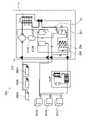
- Fig. 2 is a refrigerant circuit 1 diagram illustrating a configuration of a refrigerant circuit of a first embodiment.
- the shown refrigerant circuit uses CO 2 as refrigerant and includes one compressor 10, a heat-source-side heat exchanger of an outdoor unit of a so called “Conveni-Pack”, including usually coolers such as refrigerators and freezers for storing food etc. and air conditioners (indoor units) for cooling/heating an inside of a room, particularly a show room/shopping room.
- Conveni-Pack usually coolers such as refrigerators and freezers for storing food etc.
- air conditioners indoor units for cooling/heating an inside of a room, particularly a show room/shopping room.
- the refrigerant circuit only one indoor unit and one cooler are illustrated as example, but the refrigerant circuit can naturally include several coolers and air conditioners.
- the shown refrigerant circuit further includes a thermal storage unit 100 and a heat exchange unit 200, which will be explained later in more detail.
- the thermal storage unit 100 includes a thermal storage 20 including/accumulating a thermal storage material 21, which is a phase changing material (PCM).
- the shown refrigerant circuit further includes a first fluid communication pipe 30 that connects a fluid side of the heat-source-side heat exchanger 11 with one side of the thermal storage 20 and a second fluid communication pipe 40 that connects the expansion device 12 and the other side of the thermal storage 20.
- the term “connect” is used in the present disclosure to define that two entities, for example the “one side of the thermal storage” and the “thermal storage”, are connected with each other by a connecting means such as a “liquid pipe” or a “gas pipe” in such a manner that a fluid like a refrigerant can be liquid-tight and gas-tight transferred/exchanged/flow from one entity to the other one.
- the connecting means provide a fluidic connection.
- the refrigerant circuit 1 further includes a first switching mechanism 31, which is located on the first fluid communication pipe 30 and fluidically connects the heat-source-side heat exchanger 11, the thermal storage 20, a third fluid communication pipe 50 and a first gas communication pipe 60 with each other, wherein the third fluid communication pipe 50 is fluidically connecting to the expansion device 12 and the first gas communication pipe 60 is fluidically connecting to a suction side of the compressor 10.
- a first switching mechanism 31 which is located on the first fluid communication pipe 30 and fluidically connects the heat-source-side heat exchanger 11, the thermal storage 20, a third fluid communication pipe 50 and a first gas communication pipe 60 with each other, wherein the third fluid communication pipe 50 is fluidically connecting to the expansion device 12 and the first gas communication pipe 60 is fluidically connecting to a suction side of the compressor 10.
- the shown refrigerant circuit 1 further includes a second switching mechanism 41 located on the second fluid communication pipe 40 and fluidically connects the thermal storage 20, the expansion device 12 and a fourth fluid communication pipe 70 with each other, wherein the fourth fluid communication pipe 70 is fluidically connecting to a utilization-side heat exchanger 80A.
- Fig. 2 also shows that the refrigerant circuit 1 further comprises a receiver 201, which is located on the third fluid communication pipe 50, between the expansion device 12 and the utilization-side heat exchanger 80A, wherein the receiver 201 is configured to separate the refrigerant coming from the expansion device 12 in a subcritical state into liquid refrigerant and gas refrigerant.
- a receiver 201 which is located on the third fluid communication pipe 50, between the expansion device 12 and the utilization-side heat exchanger 80A, wherein the receiver 201 is configured to separate the refrigerant coming from the expansion device 12 in a subcritical state into liquid refrigerant and gas refrigerant.
- the shown refrigerant circuit 1 also indicates that the refrigerant circuit 1 can further include an additional utilization-side heat exchanger 80B communicating on its liquid side with the expansion device 12 via the receiver 201 and on its gas side with the compressor 10.
- the utilization-side heat exchanger 80A can be a heat exchanger of an air-conditioner, particularly of an indoor unit, and the additional utilization-side heat exchanger 80B can be a heat exchanger of a cooler such as a refrigerator or a freezer.
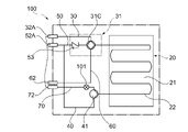
- Fig. 3 is a refrigerant circuit diagram illustrating a configuration of a thermal storage unit of a fist embodiment.
- the shown thermal storage unit 100 is part of the above described refrigerant circuit 1, wherein the switching mechanism 1 is configured according to a first alternative.
- the shown thermal storage unit 100 includes the thermal storage 20 including the above described thermal storage material 21, which is a phase changing material (PCM), a thermal storage unit gas port 62 communicating to the utilization-side heat exchanger 80A, disposed outside the thermal storage unit 100, a first thermal storage unit fluid port 72 communicating to the utilization-side heat exchanger 80A, a second thermal storage unit fluid port 32A communicating to the heat-source-side heat exchanger 11, disposed outside the thermal storage unit 100, and a third thermal storage unit fluid port 52A communicating to the expansion device 12 disposed outside the thermal storage unit 100.
- PCM phase changing material
- the shown thermal storage unit 100 further includes the first switching mechanism 31 communicating among the second thermal storage unit fluid port 32A, the third thermal storage fluid port 52A, the thermal storage unit gas port 62 and one side of the thermal storage 20, and the second switching mechanism 41 communicating among the first thermal storage unit fluid port 72, the third thermal storage unit fluid port 52A and the other side of the thermal storage 20.
- thermal storage unit 100 further includes a refrigerant heat exchange pipe 22 that is disposed inside the thermal storage 20, particularly inside the thermal storage material 21.
- the first switching mechanism 31 is fluidically connected with one side of the refrigerant heat exchange pipe 22 and the second switching mechanism 41 is fluidically connected with the other end of the refrigerant heat exchange pipe 22.
- the first switching mechanism 31 includes: a first valve 31A, which is a three-way valve, communicating among the second thermal storage unit fluid port 32A, the third thermal storage unit fluid port 52A and the thermal storage 20, and a second valve 31B, which is a three-way valve and located between the first valve 31A and the thermal storage 20, communicating among the first valve 31A, the thermal storage 20 and the thermal storage unit gas port 62.
- a first valve 31A which is a three-way valve, communicating among the second thermal storage unit fluid port 32A, the third thermal storage unit fluid port 52A and the thermal storage 20
- a second valve 31B which is a three-way valve and located between the first valve 31A and the thermal storage 20, communicating among the first valve 31A, the thermal storage 20 and the thermal storage unit gas port 62.
- a check valve 31A provided that stops a backflow from the third thermal storage unit fluid port 52A to the first valve 31A.
- the shown second switching mechanism 41 is a valve, which is a three-way valve, fluidically connecting the first thermal storage unit fluid port 72, the third thermal storage unit fluid port 52A and the thermal storage 20 with each other, wherein an expansion device 101 is located between the second switching mechanism 41 and the first thermal storage unit fluid port 72.
- the second thermal storage unit fluid communication pipe 40 is connected with the third thermal storage unit fluid communication pipe 50 between the third thermal storage unit fluid port 52A and the check valve 53.
- a thermal storage unit gas communication pipe 60 fluidically connects the thermal storage unit gas port 62 and the first switching mechanism 31, particularly the second valve 31B, with each other.
- Fig. 4 is a refrigerant circuit diagram illustrating a configuration of the thermal storage unit 100 according to a second embodiment, particularly an alternative configuration.
- the illustrated refrigerant circuit corresponds to the refrigerant circuit disclosed in Fig. 3 except the configuration of the first switching mechanism.
- the first first valve 31A is a four-way valve that fluidically connects the second thermal storage unit fluid port 32A, the thermal storage 20, the thermal storage unit gas port 62 and the third thermal storage unit fluid port 52A.
- Fig. 5 is a refrigerant circuit diagram illustrating a configuration of a thermal storage unit 100 according to a third embodiment, particularly a third alternative.
- the shown alternative does not use the above described refrigerant heat exchange pipe 22, instead uses a heat exchanger 102.
- the heat exchanger 102 is preferably a plate heat exchanger, which is on one side communicating with the first switching mechanism 31 and the second switching mechanism 41 and on the other side with the one side of the thermal storage 20 and the other side of the thermal storage 20.
- the thermal storage unit 100 includes a circulating pump 103 that is located on the second thermal storage unit fluid communication pipe 40, between the heat exchanger 102 and the thermal storage 20. Accordingly, the thermal storage has a closed loop, particularly using water as coolant.
- the circulating pump circulates the coolant through the thermal storage 20, thereby the coolant exchanges heat with the thermal storage material 21 of the thermal storage, and then to the heat exchanger 102, where the coolant again exchanges heat with the refrigerant of the refrigerant circuit 1.
- the circulating pump 103 is able to control the amount of thermal energy exchanged between the thermal storage 20, particularly the thermal storage material 21, and the refrigerant of the refrigerant circuit 1.
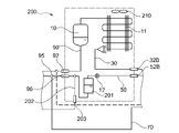
- Fig. 6 is a refrigerant circuit diagram illustrating a configuration of a heat exchange unit 200 of a first embodiment.
- the shown heat exchange unit 200 includes the compressor 10, the heat-source-side heat exchanger 11 the expansion device 12, a heat exchange unit gas port 92 communicating to the utilization-side heat exchanger 80A disposed outside the heat exchange unit 200, a first heat exchange unit fluid port 96 communicating to the utilization-side heat exchanger 80A, a second heat exchange unit fluid port 32B communicating to the heat-source-side heat exchanger 11, a third heat exchange unit fluid port 52B communicating to the expansion device 12.
- the shown second heat exchange unit fluid port 32B is fluidically connected to the above described thermal storage unit 100 disposed outside the heat exchange unit 200 and the third heat exchange unit fluid port 52B is also fluidically connected to the thermal storage unit 100.
- the shown heat exchange unit 200 further includes a heat exchange unit gas communication pipe 90 communicating between the heat exchange unit gas port 92 and the at least one compressor 10, a first heat exchange unit fluid communication pipe 30 communicating between the second heat exchange unit fluid port 32B and the heat-source-side heat exchanger 11, and a second heat exchange unit fluid communication pipe 50 communicating between the third heat exchange unit fluid port 52B and the first heat exchange unit fluid port 96.
- the expansion device 12 is located on the second heat exchange unit fluid communication pipe 50, between the first heat exchange unit fluid port 96 and the third heat exchange unit fluid port 52B.
- the shown heat exchange unit 200 further includes the above described receiver 201, which is located on the second heat exchange unit fluid communication pipe 50, between the first heat exchange unit fluid port 96 and the expansion device 12, wherein the receiver 201 is configured to separate liquid refrigerant and gas refrigerant.
- the heat exchange unit 200 further includes a fourth heat exchange unit fluid port 203 fluidically connecting the expansion device 12 and the additional utilization-side heat exchanger 80B disposed outside the heat exchange unit 200.
- the shown heat exchange unit 200 further includes a third heat exchange unit fluid communication pipe 202 fluidically connecting the fourth heat exchange unit fluid port 203 with the expansion device 12 and is connected with the second heat exchange unit fluid communication pipe 50 between the first heat exchange unit fluid port 96 and the receiver 201.
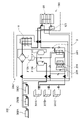
- Fig. 7 is a refrigerant circuit diagram illustrating a configuration of a refrigeration apparatus 300 of a first embodiment during a normal refrigeration and cooling operation.
- the shown refrigeration apparatus 300 includes the above described refrigerant circuit 1, the thermal storage unit 100 and the heat exchange unit 200, which are further detailed for explanatory purposes.
- the shown heat exchange unit 200 further includes a subcooling heat exchanger 204, which is located between the first heat exchange unit fluid port 96 and the receiver 201.
- the refrigeration apparatus 300 includes three coolers such as refrigerators and freezers for storing food etc. and three air conditioners (indoor units) for cooling/heating an inside of a room, particularly a show room/shopping room.
- the three indoor units are each provided with one utilization-side heat exchanger 380A-380C and the three refrigerators are each provided with one additional utilization-side heat exchanger 301A-301C.
- the shown heat exchange unit 200 further includes a second compressor 310B and a third compressor 310C that are provided parallel to each other and upstream of the above described compressor 10 of the basic configuration.
- the three compressors 310A-310B build a two-stage compressor system, wherein the second compressor 310B communicates with the additional utilization-side heat exchangers 301A-301C to build a refrigeration circuit and the third compressor 310C communicates with the utilization-side heat exchangers 380A-380C to build an air-conditioning circuit.
- the three compressors 310A-310C can be variable capacity compressors and/or fixed capacity compressors, depending on the requirements of the refrigerant apparatus. All of the three compressors 310A-310C are hermetic scroll compressors.
- the shown heat exchange unit 200 further includes an injection pipe 206 fluidically connecting a gas side of the receiver 201 with a suction side of the first compressor 10, 310A, wherein the injection pipe 206 is configured to inject intermediate-pressure refrigerant collected by the receiver 201 into the first compressor 10, 310A.
- the injection pipe 206 joins with two high-pressure pipes 207, 208 communicating between high-pressure sides of the second compressor 310B and the third compressor 310C and the suction side of the first compressor 10, 310A, before connecting to a suction side of the first compressor 10, 310A.
- the injection pipe 206 is provided with an expansion device 207, which is preferably located before the connection point of the injection pipe 206 with the high-pressure pipes 207, 208.
- an expansion device 207 which is preferably located before the connection point of the injection pipe 206 with the high-pressure pipes 207, 208.
- FIG. 7 illustrates the refrigeration apparatus 300 in a normal refrigeration and cooling operation. Accordingly, all three compressors 310A-310C are turned on, which means, the second compressor 310B draws low pressure refrigerant from the additional utilization-side heat exchangers 301A-301C of the three coolers and the third compressor 310C draws refrigerant from the utilization-side heat exchanger 380C of one of the three indoor units. Via the high-pressure pipes 207, 208 the two compressors 310B, 310C provide intermediate-pressure refrigerant to the first compressor 310A, which further compresses the refrigerant and discharges high-pressure refrigerant which flows to the heat-source-side heat exchanger 11, which acts as a gas cooler.
- Such refrigerant is cooled by dissipating heat to outdoor air supplied by an outdoor fan.
- the high-pressure refrigerant flowing out from the heat-source-side heat exchanger 11 flows via the first fluid communication pipe 30 to the first switching mechanism 31, particularly the first valve 31A, which is a three-way valve.
- the three-way valve 31A is in a state, in which the first fluid communication pipe 30 is communicating with the third fluid communication pipe 50 and a flow to the second valve 31B is blocked.
- the high-pressure refrigerant flows directly to the expansion device 12, which is an expansion valve, without flowing through the thermal storage 20 or exchanging heat with the thermal storage 20 via the heat exchanger 102.
- the expansion device 12 Flowing through the expansion device 12, the pressure of the cooled high-pressure refrigerant is reduced, and the refrigerant is changed into intermediate-pressure refrigerant in a gas-liquid two-phase state (subcritical refrigerant).
- the intermediate-pressure refrigerant flows to the receiver 201, a part of the refrigerant, particularly liquid intermediate-pressure refrigerant, flows from the receiver 201 to a first flow path 204A of the subcooling heat exchanger 204.
- the refrigerant flowing into the first flow path 204A is cooled by intermediate-pressure refrigerant flowing through the second flow path 204B, and the degree of subcooling of such refrigerant is increased.
- a part of the so subcooled liquid refrigerant flows through an expansion device 205, particularly a subcooling expansion valve, thereby reducing the pressure of the intermediate-pressure refrigerant further.
- the intermediate-pressure refrigerant flows into the second flow path 204B of the subcooling heat exchanger 204 and is evaporated by absorbing heat from the refrigerant flowing through the first flow path 204A of the subcooling heat exchanger 204.
- the subcooled intermediate-pressure refrigerant flows so as to be branched into two main pipes providing the refrigerant to the refrigeration circuit and the air-conditioning circuit, where the refrigerant is branched again into three pipes providing the utilization-side heat exchangers 380A-380C of the indoor units and the additional utilization-side heat exchangers 301A-301C of the coolers with liquid refrigerant.
- the refrigerant flows through an expansion device, particularly an air-conditioning expansion valve or a cooler expansion valve, where the pressure of the intermediate-pressure refrigerant is reduced.
- Such refrigerant flows through the utilization-side heat exchangers and is evaporated by absorbing heat from example room air supplied by an air-conditioning fan of the indoor units.
- the evaporated refrigerant of the utilization-side heat exchangers 380A-380C of the indoor units is rejoined and flows via a suction pipe back to a suction side of the third compressor 310C.
- the evaporated refrigerant of the additional utilization-side heat exchangers 301A-301C of the coolers is rejoined and flows via a suction pipe back to a suction side of the second compressor 310B.
- the air-conditioning circuit and the refrigeration circuit are a closed loop.
- the evaporated refrigerant of the subcooling heat exchanger 204 is joined with intermediate-pressure refrigerant discharged from the second compressor 310B and the third compressor 310C and provided to the suction side of the first compressor 310A.
- gas intermediate-pressure refrigerant separated by the receiver 201 from the liquid intermediate-pressure refrigerant of the supercritical refrigerant flows through an expansion device to reduce the pressure to a similar pressure as the pressure of the intermediate-pressure refrigerant discharged by the second compressor 310B and the third compressor 310C.
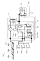
- Refrigeration operation using the thermal storage Fig. 8 is a refrigerant circuit diagram illustrating the refrigeration apparatus 300 of Fig. 7 during a refrigeration operation using the thermal storage.
- the first switching mechanism 31, in particular the first and second valve, and the second switching valve are set in such a way that the high-pressure refrigerant flowing out from the heat-source-side heat exchanger 11 flows via the first fluid communication pipe 30 into the first and second valve and then into the thermal storage, thereby exchanging heat with the thermal storage 20.
- the high-pressure refrigerant is cooled.
- the high-pressure refrigerant flows via the second switching mechanism via the expansion device 12 back to the receiver 201.
- the pressure of the cooled high-pressure refrigerant is reduced and the refrigerant is changed into intermediate-pressure refrigerant in a gas-liquid two-phase state (supercritical refrigerant).
- a part of the refrigerant flows then from the receiver 201 to the first flow path 204A of the subcooling heat exchanger 204.
- the refrigerant flowing into the first flow path 204A is cooled by intermediate-pressure refrigerant flowing through the second flow path 204B, and the degree of subcooling of such refrigerant is increased.
- a part of the so subcooled liquid refrigerant flows through the expansion device 205 thereby reducing the pressure of the intermediate-pressure refrigerant further.
- the intermediate-pressure refrigerant flows into the second flow path 204B of the subcooling heat exchanger 204 and is evaporated by absorbing heat from the refrigerant flowing through the first flow path 204A of the subcooling heat exchanger 204.
- the subcooled intermediate-pressure refrigerant flows then so as to provide the refrigerant only to the refrigeration circuit and not to the air-conditioning circuit, where the refrigerant is branched again into three pipes providing the additional utilization-side heat exchangers 301A-301C of the coolers with liquid refrigerant.
- the refrigerant flows through the cooler expansion valve, where the pressure of the intermediate-pressure refrigerant is reduced.
- Such refrigerant flows through the additional utilization-side heat exchangers and is evaporated by absorbing heat from storage room air within the coolers.
- the third compressor 310 is turned off.
- the second compressor 310 draws low pressure refrigerant from the additional utilization-side heat exchangers 301A-301C of the coolers and provides intermediate-pressure refrigerant via the high-pressure pipe 207 to the first compressor 310A, which further compresses the refrigerant and discharges high-pressure refrigerant which flows to the heat-source-side heat exchanger 11, which acts as a gas cooler.
- Such refrigerant is cooled by dissipating heat to outdoor air supplied by an outdoor fan.
- the high-pressure refrigerant flowing out from the heat-source-side heat exchanger 11 flows then via the first fluid communication pipe 30 back to the first switching mechanism 31, thereby closing the refrigerant circuit.
- FIG. 9 is a refrigerant circuit diagram illustrating the refrigeration apparatus of Fig. 7 during a refrigeration and cooling operation using the thermal storage.
- the refrigeration and cooling operation using the thermal storage is similar to the above with regard to Fig 8 described refrigeration (only) operation using the thermal storage, except that all three compressors 310A to 310C are in use.
- the second compressor 310B draws low pressure refrigerant from the additional utilization-side heat exchangers 301A-301C of the three coolers and the third compressor 310C draws refrigerant from the utilization-side heat exchanger 380C of one of the three indoor units, which is the provided as intermediate-pressure refrigerant to the first compressor 310A, which further compresses the refrigerant and discharges high-pressure refrigerant which flows to the heat-source-side heat exchanger 11.
- Such refrigerant flows then as described above through the thermal storage 20, the expansion device 12, the receiver 201, the subcooling heat exchanger 204 and is then branched into the two main pipes providing the refrigerant to the refrigeration circuit and the air-conditioning circuit, closing the refrigerant circuit.
- Fig. 10 is a refrigerant circuit diagram illustrating the refrigeration apparatus of Fig. 7 during an only charging operation of the thermal storage.
- the second compressor 310B is turned off.
- the third compressor 310C draws the refrigerant directly from the thermal storage 20 and provides intermediate-pressure refrigerant to the first compressor which compresses the refrigerant further and discharges high-pressure refrigerant which flows to the heat-source-side heat exchanger 11, which acts as a gas cooler.
- the high-pressure refrigerant flowing out from the heat-source-side heat exchanger 11 flows then via the first fluid communication pipe 30 to the first switching mechanism 31.
- the first valve 31A is set in such a manner that the high-pressure refrigerant flows as described above with Fig. 7 directly to the expansion device 12.
- the intermediate-pressure refrigerant in a gas-liquid two-phase state flows to the receiver 201 and from there liquid intermediate-pressure refrigerant flows then to the first flow path 204A of the subcooling heat exchanger 204.
- the refrigerant flowing into the first flow path 204A is cooled by intermediate-pressure refrigerant flowing through the second flow path 204B, and the degree of subcooling of such refrigerant is increased.
- the subcooled intermediate-pressure refrigerant flows then via the second valve 31B back to the thermal storage 20 and by flowing through the thermal storage 20 cools the thermal storage 20, in particular the thermal storage material, thereby charges the thermal storage with cold.
- FIG. 11 is a refrigerant circuit diagram illustrating the refrigeration apparatus of Fig. 7 during a refrigeration operation while charging the thermal storage.
- the refrigeration operation while charging the thermal storage is similar to the above with regard to Fig. 10 described only charging operation of the thermal storage, except that all three compressors 310A-310C are in use and that the second compressor 310B connects the additional utilization-side heat exchangers 301A-301C of the coolers to the refrigerant circuit 1.
- the thermal storage 20 can be charged while performing a refrigeration operation.
- Fig. 12 is a refrigerant circuit diagram illustrating a configuration of a refrigeration apparatus 300 of a second embodiment having a capacity increasing unit 320.
- the refrigerant apparatus 300 of the second embodiment mostly corresponds to the refrigerant apparatus of the first embodiment described with regard to Fig. 7.
- the thermal storage unit 100 instead of being provided with the thermal storage unit 100, the two connecting pipes connecting the second heat exchanger unit fluid port 32B and the third heat exchanger unit fluid port 52B have an open end. Meaning, the unit connected via the second and third heat exchanger unit fluid ports 32B and 52B with the refrigerant apparatus 300, in particular with the heat exchanger unit 200, is not shown.
- the thermal storage unit 100 instead of the thermal storage unit 100 also a heat exchanger, particularly a plate heat exchanger, a capacity increasing unit or a combi unit including a thermal storage unit and a capacity increasing unit can be connected to the heat exchanger unit 200.
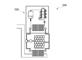
- Fig. 13 is a refrigerant circuit diagram illustrating a capacity increasing unit 320.
- the capacity increasing unit 320 is basically an independent refrigerant circuit that can be added to or connected with the refrigerant apparatus 300, in order to increase the refrigeration and cooling capacity of the refrigerant apparatus 300.
- the capacity increasing unit 320 includes a heat exchanger, a compressor and an expansion device which build a closed refrigerant circuit.
- the heat exchanger is configured to exchange heat with the heat exchanger unit 200. Therefore, the heat exchanger can be connected with the second and third heat exchanger unit fluid ports 32B and 52B.
- the capacity increasing unit 320 is provided with a heat-source-side heat exchanger that cools down the refrigerant flowing there through by dissipating heat to outdoor air supplied by an outdoor fan.
- Fig. 14 is a refrigerant circuit diagram illustrating a combi unit 330 having a capacity increasing unit 320 and a thermal storage unit.
- the capacity increasing unit 320 includes a heat exchanger, a compressor and an expansion device which build a closed refrigerant circuit.
- the thermal storage unit is arranged between the heat exchanger unit 200 and the thermal storage unit.
- the combi unit 330 additionally includes a circulating pump that circulates a refrigerant or a coolant like water, cooled by the capacity increasing unit through the thermal storage unit, in order to charge the thermal storage unit with thermal energy, particularly cold.
- the thermal storage unit is provided with a heat exchanger that is used to exchange heat with the refrigerant circuit of the refrigerant apparatus 300, in particular with the heat exchanger unit 200.
- the capacity increasing unit may include a closed refrigerant circuit including a heat exchanger, a compressor, a heat-source-side heat exchanger cooled by a fan and an expansion device, wherein the heat exchanger exchanges heat with the heat exchange unit.
- the combi unit may include a capacity increasing unit, comprising a closed refrigerant circuit including a heat exchanger, a compressor, a heat-source-side heat exchanger cooled by a fan and an expansion device, and a thermal storage unit comprising a heat exchanger, a thermal storage, including a thermal storage material, particularly a phase changing material (PCM), and a circulating pump, wherein the heat exchanger exchanges heat with the heat exchange unit.
- a capacity increasing unit comprising a closed refrigerant circuit including a heat exchanger, a compressor, a heat-source-side heat exchanger cooled by a fan and an expansion device
- a thermal storage unit comprising a heat exchanger, a thermal storage, including a thermal storage material, particularly a phase changing material (PCM), and a circulating pump, wherein the heat exchanger exchanges heat with the heat exchange unit.
- PCM phase changing material
Landscapes
- Engineering & Computer Science (AREA)
- Physics & Mathematics (AREA)
- Mechanical Engineering (AREA)
- Thermal Sciences (AREA)
- General Engineering & Computer Science (AREA)
- Chemical & Material Sciences (AREA)
- Chemical Kinetics & Catalysis (AREA)
- Compression-Type Refrigeration Machines With Reversible Cycles (AREA)
- Other Air-Conditioning Systems (AREA)
Abstract
Description
DESCRIPTION OF CONTROL MODES
First Example: Normal refrigeration and cooling operation
Fig. 8 is a refrigerant circuit diagram illustrating the
Fig. 9 is a refrigerant circuit diagram illustrating the refrigeration apparatus of Fig. 7 during a refrigeration and cooling operation using the thermal storage. The refrigeration and cooling operation using the thermal storage is similar to the above with regard to Fig 8 described refrigeration (only) operation using the thermal storage, except that all three
Fig. 10 is a refrigerant circuit diagram illustrating the refrigeration apparatus of Fig. 7 during an only charging operation of the thermal storage.
Fig. 11 is a refrigerant circuit diagram illustrating the refrigeration apparatus of Fig. 7 during a refrigeration operation while charging the thermal storage.
10 Compressor (First Compressor)
11 Heat-source-side heat exchanger
12 Expansion Device
20 Thermal Storage
21 Thermal Storage Material
22 Refrigerant Heat Exchange Pipe
30 First Fluid Communication Pipe
31 First Switching Mechanism
40 Second Fluid Communication Pipe
41 Second Switching Mechanism
50 Third Fluid Communication Pipe
60 First Gas Communication Pipe
70 Fourth
80A Utilization-side Heat Exchanger
80B Additional Utilization-side Heat Exchanger
90 Heat Exchange Unit Gas Communication pipe
92 Heat Exchange
96 First Heat Exchange Unit Fluid Port
100 Thermal Storage Unit
72 First Thermal Storage Unit Fluid Port
32A Second Thermal Storage Unit Fluid Port
52A Third Thermal Storage Unit Fluid Port
62 Thermal Storage Unit Gas Port
31A First Valve
31B Second Valve
53 Check Valve
101 Expansion Device
102 Heat Exchanger
103 Circulating Pump
200 Heat Exchanger Unit
96 First Heat Exchanger Unit Fluid Port
32B Second Heat Exchanger Unit Fluid Port
52B Third Heat Exchanger Unit Fluid Port
201 Receiver
202 Third Heat Exchanger Unit Fluid Communication Pipe
203 Fourth Heat Exchanger Unit Fluid Port
204 Subcooling Heat Exchanger
205 Expansion Device (Subcooling Expansion Valve)
206 injection pipe
207 high pressure pipe
208 high pressure pipe
209 expansion device
210 fan
300 Refrigeration Apparatus
301A-301C Additional Utilization-side Heat Exchanger
310A First Compressor
310B Second Compressor
310C Third Compressor
320 Capacity Increasing Unit
330 Combi Unit
380A-380C Utilization-side Heat Exchanger
[PTL 2] EP 2 844 924 B1
Claims (15)
- A refrigerant circuit (1) for a refrigeration apparatus (300) with a thermal storage, which is using CO2 as refrigerant, comprising:
at least one compressor (10),
a heat-source-side heat exchanger (11)
an expansion device (12), and
a thermal storage (20), including a thermal storage material (21), particularly a phase changing material (PCM) from the group: organic PCMs like bio-based, paraffin, carbohydrate or lipid derived, or water,
characterized in that
the refrigerant circuit (1) further comprises:
a first fluid communication pipe (30) communicating between a fluid side of the heat-source-side heat exchanger (11) and one side of the thermal storage (20), and
a second fluid communication pipe (40) communicating between the expansion device (12) and the other side of the thermal storage (20). - The refrigerant circuit (1) according to claim 1, further comprises a first switching mechanism (31) located on the first fluid communication pipe (30) and communicating among the heat-source-side heat exchanger (11), the thermal storage (20), a third fluid communication pipe (50), and a first gas communication pipe (60), wherein the third fluid communication pipe (50) communicates to the expansion device (12) and the first gas communication pipe (60) communicates to a suction side of the compressor (10).
- The refrigerant circuit (1) according to claim 2, wherein the first switching mechanism (31) comprises:
a first valve (31A), which is a three-way valve, communicating among the heat-source-side heat exchanger (11), the expansion device (12) and the thermal storage (20), and
a second valve (31B), which is a three-way valve and located between the first valve (31A) and the thermal storage (20), communicating among the first valve (31A), the thermal storage (20) and the first gas communication pipe (60). - The refrigerant circuit (1) according to claim 2, wherein the first switching mechanism (31) comprises:
a first valve (31C), which is a four-way valve, communicating among the heat-source-side heat exchanger (11), the thermal storage (20), the first gas communication pipe (60) and the expansion device (12), wherein the first switching mechanism (31) further comprises a check valve (53) that stops a backflow from the third fluid communication pipe (50) to the first valve (31C). - The refrigerant circuit (1) according any one of claims 2 to 4, further comprises a second switching mechanism (41) located on the second fluid communication pipe (40) and communicating among the thermal storage (20), the expansion device (12) and a fourth fluid communication pipe (70), wherein the fourth fluid communication pipe (70) is communicating to a utilization-side heat exchanger (80A).
- The refrigerant circuit (1) according to claim 5, wherein the second switching mechanism (41) is a valve, which is a three-way valve, communicating among the thermal storage (20), the expansion valve (12) and the utilization-side heat exchanger (80A),
wherein an expansion device (101) is provided on the fourth fluid communication pipe (70), located between the second switching mechanism (41) and the utilization-side heat exchanger (80A). - The refrigerant circuit (1) according to any one of the preceding claims, further comprising a receiver (201), which is located on the third fluid communication pipe (50), between the expansion device (12) and a/the utilization-side heat exchanger (80A), wherein the receiver (201) is configured to separate liquid refrigerant from gas refrigerant.
- The refrigerant circuit (1) according to any one of the preceding claims, further comprising a subcooling heat exchanger (204), which is preferably located between a/the utilization-side heat exchanger (80A) and the expansion device (12), more preferably between the utilization-side heat exchanger (80A) and a/the receiver (201).
- The refrigerant circuit according to any of the preceding claims and claim 5, further comprising:
an expansion device (101), particularly a storage side expansion valve (EV), located on the fourth fluid communication pipe (70) and between the second switching mechanism (41) and the utilization-side heat exchanger (80A), and
a controller configured to select modes of operation,
wherein the modes comprise:
a normal refrigeration and/or cooling mode, a cold storage making mode and a cold storage using mode, wherein particularly:
in the normal refrigeration and/or cooling mode the first switching mechanism (31) is set so that the first fluid communication pipe (30) and the third fluid communication pipe (50) are communicated, and the expansion device (101) is closed,
in the cold storage making mode the first switching mechanism (31) is set so that the first fluid communication pipe (30) and the third fluid communication pipe (50) are communicated and the first gas communication pipe (60) and the thermal storage (20) are communicated, the second switching mechanism (41) is set so that the fourth fluid communication pipe (70) and the thermal storage (20) are communicated, and the expansion device (101) is opened, and
in the cold storage using mode the first switching mechanism (31) is set so that first fluid communication pipe (30) and the thermal storage (20) are communicated, the second switching mechanism (41) is set so that the second fluid communication pipe (40) and the thermal storage (20) are communicated, and the expansion device (101) is closed. - The refrigerant circuit according to claim 9, further comprising an outside temperature sensor (T5), a gas cooler out temperature sensor (T2), a thermal storage medium temperature sensor (T4), and a discharge side pressure sensor (P1), provided on the high pressure side of the at least one compressor (10).
- The refrigerant circuit according to any one of the preceding claims, further comprising a thermal storage unit (100) including the thermal storage (20) and comprising a water circuit, a refrigerant to phase change material (PCM) circuit or a refrigerant to water to phase change material (PCM) circuit having a heat exchanger (102), particularly a plate heat exchanger, and a circulating pump (103).
- The refrigerant circuit according to any one of the claims 5, 6, 9 and 10, further comprising a thermal storage unit (100) including the first switching mechanism (31) and the second switching mechanism (41).
- The refrigerant circuit according to claims 8 with the receiver (201), further comprising a heat exchange unit (200) including the receiver (201) and the subcooling heat exchanger (204).
- Method for controlling a refrigerant circuit, particularly the refrigerant circuit (1) according to any one of the preceding claims, for a refrigerant apparatus with a thermal storage (20) which is using CO2 as refrigerant, the method comprising different modes of operation, wherein the modes comprise:
a normal refrigeration and/or cooling mode, a cold storage making mode and a cold storage using mode, wherein:
in the normal refrigeration and/or cooling mode a first switching mechanism (31) is set so that a first fluid communication pipe (30) and a third fluid communication pipe (50) are communicated, and an expansion device (101) is closed,
in the cold storage making mode the first switching mechanism (31) is set so that the first fluid communication pipe (30) and the third fluid communication pipe (50) are communicated and a first gas communication pipe (60) and the thermal storage (20) are communicated, a second switching mechanism (41) is set so that a fourth fluid communication pipe (70) and the thermal storage (20) are communicated, and the expansion device (101) is opened, and
in the cold storage using mode the first switching mechanism (31) is set so that first fluid communication pipe (30) and the thermal storage (20) are communicated, the second switching mechanism (41) is set so that the second fluid communication pipe (40) and the thermal storage (20) are communicated, and the expansion device (101) is closed. - The method according to claim 14, wherein:
the first fluid communication pipe (30) communicates between a fluid side of a heat-source-side heat exchanger (11) and one side of the thermal storage (20),
the second fluid communication pipe (40) communicates between an expansion device (12) and the other side of the thermal storage (20),
the third fluid communication pipe (50) communicates to the expansion device (12), and
the first gas communication pipe (60) communicates to a suction side of a compressor (10).
Priority Applications (3)
| Application Number | Priority Date | Filing Date | Title |
|---|---|---|---|
| US18/032,961 US12607388B2 (en) | 2020-11-05 | 2021-11-04 | Refrigerant circuit for a refrigeration apparatus with a thermal storage and method for controlling a refrigerant circuit |
| CN202180072291.3A CN116507860A (en) | 2020-11-05 | 2021-11-04 | Refrigerant circuit for a refrigeration device with heat storage and method for controlling the refrigerant circuit |
| JP2023524921A JP7645371B2 (en) | 2020-11-05 | 2021-11-04 | Refrigerant circuit for a cooling device having a heat accumulator and method for controlling the refrigerant circuit |
Applications Claiming Priority (6)
| Application Number | Priority Date | Filing Date | Title |
|---|---|---|---|
| EP20205893.9A EP3995758B1 (en) | 2020-11-05 | 2020-11-05 | Heat exchange unit for a refrigeration apparatus with a thermal storage and using co2 as refrigerant |
| EP20205899.6A EP3995761A1 (en) | 2020-11-05 | 2020-11-05 | Refrigerant circuit for a refrigeration apparatus with a thermal storage and method forcontrolling a refrigerant circuit |
| EP20205894.7A EP3995760B1 (en) | 2020-11-05 | 2020-11-05 | Thermal storage unit for a refrigeration apparatus with a thermal storage and using co2 as refrigerant |
| EP20205899.6 | 2020-11-05 | ||
| EP20205894.7 | 2020-11-05 | ||
| EP20205893.9 | 2020-11-05 |
Publications (1)
| Publication Number | Publication Date |
|---|---|
| WO2022097680A1 true WO2022097680A1 (en) | 2022-05-12 |
Family
ID=78621954
Family Applications (1)
| Application Number | Title | Priority Date | Filing Date |
|---|---|---|---|
| PCT/JP2021/040591 Ceased WO2022097680A1 (en) | 2020-11-05 | 2021-11-04 | Refrigerant circuit for a refrigeration apparatus with a thermal storage and method for controlling a refrigerant circuit |
Country Status (3)
| Country | Link |
|---|---|
| US (1) | US12607388B2 (en) |
| JP (1) | JP7645371B2 (en) |
| WO (1) | WO2022097680A1 (en) |
Citations (6)
| Publication number | Priority date | Publication date | Assignee | Title |
|---|---|---|---|---|
| WO2000033002A1 (en) * | 1998-12-01 | 2000-06-08 | Daikin Industries,Ltd. | Refrigerator |
| EP1550830A1 (en) * | 2002-10-08 | 2005-07-06 | Matsushita Electric Industrial Co., Ltd. | Heat pump system |
| EP2402681A1 (en) | 2009-02-27 | 2012-01-04 | Daikin Industries, Ltd. | Refrigeration unit |
| EP2844924A1 (en) | 2012-05-03 | 2015-03-11 | Carrier Corporation | Air conditioning system having supercooled phase change material |
| EP3222934A1 (en) * | 2014-12-26 | 2017-09-27 | Daikin Industries, Ltd. | Regenerative air conditioner |
| US20190264933A1 (en) * | 2018-02-23 | 2019-08-29 | Emerson Climate Technologies, Inc. | Climate-Control System With Thermal Storage Device |
Family Cites Families (11)
| Publication number | Priority date | Publication date | Assignee | Title |
|---|---|---|---|---|
| JP2503659B2 (en) * | 1989-06-23 | 1996-06-05 | ダイキン工業株式会社 | Heat storage type air conditioner |
| JP2004293889A (en) * | 2003-03-26 | 2004-10-21 | Mitsubishi Heavy Ind Ltd | Ice thermal storage unit, ice thermal storage type air conditioner and its operating method |
| JP2006003023A (en) | 2004-06-18 | 2006-01-05 | Sanyo Electric Co Ltd | Refrigerating unit |
| EP2469195B1 (en) * | 2009-09-29 | 2017-10-25 | Mitsubishi Electric Corporation | Heat storage water-heating and air-conditioning machine |
| KR101325319B1 (en) * | 2011-10-25 | 2013-11-08 | 엘지전자 주식회사 | a regenerative air-conditioning apparatus |
| WO2014061131A1 (en) * | 2012-10-18 | 2014-04-24 | ダイキン工業株式会社 | Air conditioner |
| JP6188932B2 (en) | 2014-05-15 | 2017-08-30 | 三菱電機株式会社 | Refrigeration cycle apparatus and air conditioner equipped with the refrigeration cycle apparatus |
| WO2015177852A1 (en) * | 2014-05-19 | 2015-11-26 | 三菱電機株式会社 | Refrigeration cycle device |
| KR101591188B1 (en) * | 2014-07-07 | 2016-02-18 | 엘지전자 주식회사 | A a regenerative air-conditioning apparatus and a method controlling the same |
| JP6020549B2 (en) | 2014-12-26 | 2016-11-02 | ダイキン工業株式会社 | Thermal storage air conditioner |
| JP6635223B1 (en) | 2018-09-28 | 2020-01-22 | ダイキン工業株式会社 | Air conditioning system |
-
2021
- 2021-11-04 WO PCT/JP2021/040591 patent/WO2022097680A1/en not_active Ceased
- 2021-11-04 JP JP2023524921A patent/JP7645371B2/en active Active
- 2021-11-04 US US18/032,961 patent/US12607388B2/en active Active
Patent Citations (7)
| Publication number | Priority date | Publication date | Assignee | Title |
|---|---|---|---|---|
| WO2000033002A1 (en) * | 1998-12-01 | 2000-06-08 | Daikin Industries,Ltd. | Refrigerator |
| EP1550830A1 (en) * | 2002-10-08 | 2005-07-06 | Matsushita Electric Industrial Co., Ltd. | Heat pump system |
| EP2402681A1 (en) | 2009-02-27 | 2012-01-04 | Daikin Industries, Ltd. | Refrigeration unit |
| EP2844924A1 (en) | 2012-05-03 | 2015-03-11 | Carrier Corporation | Air conditioning system having supercooled phase change material |
| EP2844924B1 (en) | 2012-05-03 | 2019-04-03 | Carrier Corporation | Air conditioning system having supercooled phase change material |
| EP3222934A1 (en) * | 2014-12-26 | 2017-09-27 | Daikin Industries, Ltd. | Regenerative air conditioner |
| US20190264933A1 (en) * | 2018-02-23 | 2019-08-29 | Emerson Climate Technologies, Inc. | Climate-Control System With Thermal Storage Device |
Also Published As
| Publication number | Publication date |
|---|---|
| JP2023546495A (en) | 2023-11-02 |
| JP7645371B2 (en) | 2025-03-13 |
| US20230392829A1 (en) | 2023-12-07 |
| US12607388B2 (en) | 2026-04-21 |
Similar Documents
| Publication | Publication Date | Title |
|---|---|---|
| US11585608B2 (en) | Climate-control system having thermal storage tank | |
| JP2894421B2 (en) | Thermal storage type air conditioner and defrosting method | |
| KR101638675B1 (en) | Combined binary refrigeration cycle apparatus | |
| JP3352469B2 (en) | Air conditioner | |
| EP3995758B1 (en) | Heat exchange unit for a refrigeration apparatus with a thermal storage and using co2 as refrigerant | |
| EP2584285B1 (en) | Refrigerating air-conditioning device | |
| JP3975664B2 (en) | Refrigerating refrigerator, operation method of freezing refrigerator | |
| JP3906637B2 (en) | Freezer refrigerator | |
| JP4258363B2 (en) | Refrigeration air conditioner, operation method of refrigeration air conditioner | |
| EP3995760B1 (en) | Thermal storage unit for a refrigeration apparatus with a thermal storage and using co2 as refrigerant | |
| US12607388B2 (en) | Refrigerant circuit for a refrigeration apparatus with a thermal storage and method for controlling a refrigerant circuit | |
| JP2014016057A (en) | Air conditioner | |
| JP4651452B2 (en) | Refrigeration air conditioner | |
| CN114183834A (en) | Air conditioner | |
| EP3995761A1 (en) | Refrigerant circuit for a refrigeration apparatus with a thermal storage and method forcontrolling a refrigerant circuit | |
| CN100526767C (en) | Refrigeration system | |
| JP4169080B2 (en) | Freezer refrigerator | |
| JP3966262B2 (en) | Freezer refrigerator | |
| JPWO2015177852A1 (en) | Refrigeration cycle equipment | |
| JP2757660B2 (en) | Thermal storage type air conditioner | |
| JP4104519B2 (en) | Refrigeration system | |
| JP3783153B2 (en) | Air conditioner | |
| JP3614626B2 (en) | Air conditioner and method of operating air conditioner | |
| CN223165658U (en) | Energy storage air conditioning system | |
| JPH04257660A (en) | Two-stage compression refrigeration cycle equipment |
Legal Events
| Date | Code | Title | Description |
|---|---|---|---|
| 121 | Ep: the epo has been informed by wipo that ep was designated in this application |
Ref document number: 21807297 Country of ref document: EP Kind code of ref document: A1 |
|
| WWE | Wipo information: entry into national phase |
Ref document number: 202180072291.3 Country of ref document: CN |
|
| WWE | Wipo information: entry into national phase |
Ref document number: 2023524921 Country of ref document: JP |
|
| NENP | Non-entry into the national phase |
Ref country code: DE |
|
| 122 | Ep: pct application non-entry in european phase |
Ref document number: 21807297 Country of ref document: EP Kind code of ref document: A1 |