EP3995760B1 - Thermal storage unit for a refrigeration apparatus with a thermal storage and using co2 as refrigerant - Google Patents
Thermal storage unit for a refrigeration apparatus with a thermal storage and using co2 as refrigerant Download PDFInfo
- Publication number
- EP3995760B1 EP3995760B1 EP20205894.7A EP20205894A EP3995760B1 EP 3995760 B1 EP3995760 B1 EP 3995760B1 EP 20205894 A EP20205894 A EP 20205894A EP 3995760 B1 EP3995760 B1 EP 3995760B1
- Authority
- EP
- European Patent Office
- Prior art keywords
- thermal storage
- storage unit
- refrigerant
- fluid port
- heat exchanger
- Prior art date
- Legal status (The legal status is an assumption and is not a legal conclusion. Google has not performed a legal analysis and makes no representation as to the accuracy of the status listed.)
- Active
Links
- 239000003507 refrigerant Substances 0.000 title claims description 208
- 238000005057 refrigeration Methods 0.000 title claims description 47
- 239000012530 fluid Substances 0.000 claims description 138
- 238000004891 communication Methods 0.000 claims description 64
- 230000007246 mechanism Effects 0.000 claims description 51
- 239000012782 phase change material Substances 0.000 claims description 38
- 239000011232 storage material Substances 0.000 claims description 13
- XLYOFNOQVPJJNP-UHFFFAOYSA-N water Substances O XLYOFNOQVPJJNP-UHFFFAOYSA-N 0.000 claims description 13
- 239000000463 material Substances 0.000 claims description 9
- -1 bio-based Substances 0.000 claims description 3
- 150000001720 carbohydrates Chemical class 0.000 claims description 2
- 150000002632 lipids Chemical class 0.000 claims description 2
- 239000012188 paraffin wax Substances 0.000 claims description 2
- 238000002135 phase contrast microscopy Methods 0.000 claims description 2
- 238000010586 diagram Methods 0.000 description 26
- 238000001816 cooling Methods 0.000 description 22
- CURLTUGMZLYLDI-UHFFFAOYSA-N Carbon dioxide Chemical compound O=C=O CURLTUGMZLYLDI-UHFFFAOYSA-N 0.000 description 20
- 239000007788 liquid Substances 0.000 description 20
- 239000003570 air Substances 0.000 description 19
- 229910002092 carbon dioxide Inorganic materials 0.000 description 14
- 239000001569 carbon dioxide Substances 0.000 description 14
- 238000004378 air conditioning Methods 0.000 description 12
- 239000002826 coolant Substances 0.000 description 9
- 239000007787 solid Substances 0.000 description 7
- 238000002347 injection Methods 0.000 description 6
- 239000007924 injection Substances 0.000 description 6
- 238000010438 heat treatment Methods 0.000 description 5
- 230000007704 transition Effects 0.000 description 4
- QGZKDVFQNNGYKY-UHFFFAOYSA-N Ammonia Chemical compound N QGZKDVFQNNGYKY-UHFFFAOYSA-N 0.000 description 2
- VQTUBCCKSQIDNK-UHFFFAOYSA-N Isobutene Chemical compound CC(C)=C VQTUBCCKSQIDNK-UHFFFAOYSA-N 0.000 description 2
- CBENFWSGALASAD-UHFFFAOYSA-N Ozone Chemical compound [O-][O+]=O CBENFWSGALASAD-UHFFFAOYSA-N 0.000 description 2
- ATUOYWHBWRKTHZ-UHFFFAOYSA-N Propane Chemical compound CCC ATUOYWHBWRKTHZ-UHFFFAOYSA-N 0.000 description 2
- 239000013526 supercooled liquid Substances 0.000 description 2
- 238000010792 warming Methods 0.000 description 2
- 239000012080 ambient air Substances 0.000 description 1
- 229910021529 ammonia Inorganic materials 0.000 description 1
- 230000006835 compression Effects 0.000 description 1
- 238000007906 compression Methods 0.000 description 1
- 230000001143 conditioned effect Effects 0.000 description 1
- 230000001419 dependent effect Effects 0.000 description 1
- 238000005265 energy consumption Methods 0.000 description 1
- 238000005516 engineering process Methods 0.000 description 1
- 230000007613 environmental effect Effects 0.000 description 1
- NBVXSUQYWXRMNV-UHFFFAOYSA-N fluoromethane Chemical compound FC NBVXSUQYWXRMNV-UHFFFAOYSA-N 0.000 description 1
- 238000007710 freezing Methods 0.000 description 1
- 230000008014 freezing Effects 0.000 description 1
- 229930195733 hydrocarbon Natural products 0.000 description 1
- 150000002430 hydrocarbons Chemical class 0.000 description 1
- 230000007935 neutral effect Effects 0.000 description 1
- 231100000956 nontoxicity Toxicity 0.000 description 1
- 239000001294 propane Substances 0.000 description 1
- 230000001172 regenerating effect Effects 0.000 description 1
- 230000004044 response Effects 0.000 description 1
- 238000011144 upstream manufacturing Methods 0.000 description 1
Images


Classifications
-
- F—MECHANICAL ENGINEERING; LIGHTING; HEATING; WEAPONS; BLASTING
- F25—REFRIGERATION OR COOLING; COMBINED HEATING AND REFRIGERATION SYSTEMS; HEAT PUMP SYSTEMS; MANUFACTURE OR STORAGE OF ICE; LIQUEFACTION SOLIDIFICATION OF GASES
- F25B—REFRIGERATION MACHINES, PLANTS OR SYSTEMS; COMBINED HEATING AND REFRIGERATION SYSTEMS; HEAT PUMP SYSTEMS
- F25B41/00—Fluid-circulation arrangements
- F25B41/20—Disposition of valves, e.g. of on-off valves or flow control valves
-
- F—MECHANICAL ENGINEERING; LIGHTING; HEATING; WEAPONS; BLASTING
- F25—REFRIGERATION OR COOLING; COMBINED HEATING AND REFRIGERATION SYSTEMS; HEAT PUMP SYSTEMS; MANUFACTURE OR STORAGE OF ICE; LIQUEFACTION SOLIDIFICATION OF GASES
- F25B—REFRIGERATION MACHINES, PLANTS OR SYSTEMS; COMBINED HEATING AND REFRIGERATION SYSTEMS; HEAT PUMP SYSTEMS
- F25B13/00—Compression machines, plants or systems, with reversible cycle
-
- F—MECHANICAL ENGINEERING; LIGHTING; HEATING; WEAPONS; BLASTING
- F25—REFRIGERATION OR COOLING; COMBINED HEATING AND REFRIGERATION SYSTEMS; HEAT PUMP SYSTEMS; MANUFACTURE OR STORAGE OF ICE; LIQUEFACTION SOLIDIFICATION OF GASES
- F25B—REFRIGERATION MACHINES, PLANTS OR SYSTEMS; COMBINED HEATING AND REFRIGERATION SYSTEMS; HEAT PUMP SYSTEMS
- F25B2313/00—Compression machines, plants or systems with reversible cycle not otherwise provided for
- F25B2313/003—Indoor unit with water as a heat sink or heat source
-
- F—MECHANICAL ENGINEERING; LIGHTING; HEATING; WEAPONS; BLASTING
- F25—REFRIGERATION OR COOLING; COMBINED HEATING AND REFRIGERATION SYSTEMS; HEAT PUMP SYSTEMS; MANUFACTURE OR STORAGE OF ICE; LIQUEFACTION SOLIDIFICATION OF GASES
- F25B—REFRIGERATION MACHINES, PLANTS OR SYSTEMS; COMBINED HEATING AND REFRIGERATION SYSTEMS; HEAT PUMP SYSTEMS
- F25B2313/00—Compression machines, plants or systems with reversible cycle not otherwise provided for
- F25B2313/023—Compression machines, plants or systems with reversible cycle not otherwise provided for using multiple indoor units
- F25B2313/0233—Compression machines, plants or systems with reversible cycle not otherwise provided for using multiple indoor units in parallel arrangements
-
- F—MECHANICAL ENGINEERING; LIGHTING; HEATING; WEAPONS; BLASTING
- F25—REFRIGERATION OR COOLING; COMBINED HEATING AND REFRIGERATION SYSTEMS; HEAT PUMP SYSTEMS; MANUFACTURE OR STORAGE OF ICE; LIQUEFACTION SOLIDIFICATION OF GASES
- F25B—REFRIGERATION MACHINES, PLANTS OR SYSTEMS; COMBINED HEATING AND REFRIGERATION SYSTEMS; HEAT PUMP SYSTEMS
- F25B2339/00—Details of evaporators; Details of condensers
- F25B2339/04—Details of condensers
- F25B2339/042—Details of condensers of pcm condensers
-
- F—MECHANICAL ENGINEERING; LIGHTING; HEATING; WEAPONS; BLASTING
- F25—REFRIGERATION OR COOLING; COMBINED HEATING AND REFRIGERATION SYSTEMS; HEAT PUMP SYSTEMS; MANUFACTURE OR STORAGE OF ICE; LIQUEFACTION SOLIDIFICATION OF GASES
- F25B—REFRIGERATION MACHINES, PLANTS OR SYSTEMS; COMBINED HEATING AND REFRIGERATION SYSTEMS; HEAT PUMP SYSTEMS
- F25B2339/00—Details of evaporators; Details of condensers
- F25B2339/04—Details of condensers
- F25B2339/047—Water-cooled condensers
-
- F—MECHANICAL ENGINEERING; LIGHTING; HEATING; WEAPONS; BLASTING
- F25—REFRIGERATION OR COOLING; COMBINED HEATING AND REFRIGERATION SYSTEMS; HEAT PUMP SYSTEMS; MANUFACTURE OR STORAGE OF ICE; LIQUEFACTION SOLIDIFICATION OF GASES
- F25B—REFRIGERATION MACHINES, PLANTS OR SYSTEMS; COMBINED HEATING AND REFRIGERATION SYSTEMS; HEAT PUMP SYSTEMS
- F25B2400/00—General features or devices for refrigeration machines, plants or systems, combined heating and refrigeration systems or heat-pump systems, i.e. not limited to a particular subgroup of F25B
- F25B2400/04—Refrigeration circuit bypassing means
- F25B2400/0403—Refrigeration circuit bypassing means for the condenser
-
- F—MECHANICAL ENGINEERING; LIGHTING; HEATING; WEAPONS; BLASTING
- F25—REFRIGERATION OR COOLING; COMBINED HEATING AND REFRIGERATION SYSTEMS; HEAT PUMP SYSTEMS; MANUFACTURE OR STORAGE OF ICE; LIQUEFACTION SOLIDIFICATION OF GASES
- F25B—REFRIGERATION MACHINES, PLANTS OR SYSTEMS; COMBINED HEATING AND REFRIGERATION SYSTEMS; HEAT PUMP SYSTEMS
- F25B2400/00—General features or devices for refrigeration machines, plants or systems, combined heating and refrigeration systems or heat-pump systems, i.e. not limited to a particular subgroup of F25B
- F25B2400/13—Economisers
-
- F—MECHANICAL ENGINEERING; LIGHTING; HEATING; WEAPONS; BLASTING
- F25—REFRIGERATION OR COOLING; COMBINED HEATING AND REFRIGERATION SYSTEMS; HEAT PUMP SYSTEMS; MANUFACTURE OR STORAGE OF ICE; LIQUEFACTION SOLIDIFICATION OF GASES
- F25B—REFRIGERATION MACHINES, PLANTS OR SYSTEMS; COMBINED HEATING AND REFRIGERATION SYSTEMS; HEAT PUMP SYSTEMS
- F25B2400/00—General features or devices for refrigeration machines, plants or systems, combined heating and refrigeration systems or heat-pump systems, i.e. not limited to a particular subgroup of F25B
- F25B2400/24—Storage receiver heat
-
- F—MECHANICAL ENGINEERING; LIGHTING; HEATING; WEAPONS; BLASTING
- F25—REFRIGERATION OR COOLING; COMBINED HEATING AND REFRIGERATION SYSTEMS; HEAT PUMP SYSTEMS; MANUFACTURE OR STORAGE OF ICE; LIQUEFACTION SOLIDIFICATION OF GASES
- F25B—REFRIGERATION MACHINES, PLANTS OR SYSTEMS; COMBINED HEATING AND REFRIGERATION SYSTEMS; HEAT PUMP SYSTEMS
- F25B2600/00—Control issues
- F25B2600/25—Control of valves
- F25B2600/2501—Bypass valves
-
- F—MECHANICAL ENGINEERING; LIGHTING; HEATING; WEAPONS; BLASTING
- F25—REFRIGERATION OR COOLING; COMBINED HEATING AND REFRIGERATION SYSTEMS; HEAT PUMP SYSTEMS; MANUFACTURE OR STORAGE OF ICE; LIQUEFACTION SOLIDIFICATION OF GASES
- F25B—REFRIGERATION MACHINES, PLANTS OR SYSTEMS; COMBINED HEATING AND REFRIGERATION SYSTEMS; HEAT PUMP SYSTEMS
- F25B6/00—Compression machines, plants or systems, with several condenser circuits
- F25B6/04—Compression machines, plants or systems, with several condenser circuits arranged in series
-
- Y—GENERAL TAGGING OF NEW TECHNOLOGICAL DEVELOPMENTS; GENERAL TAGGING OF CROSS-SECTIONAL TECHNOLOGIES SPANNING OVER SEVERAL SECTIONS OF THE IPC; TECHNICAL SUBJECTS COVERED BY FORMER USPC CROSS-REFERENCE ART COLLECTIONS [XRACs] AND DIGESTS
- Y02—TECHNOLOGIES OR APPLICATIONS FOR MITIGATION OR ADAPTATION AGAINST CLIMATE CHANGE
- Y02E—REDUCTION OF GREENHOUSE GAS [GHG] EMISSIONS, RELATED TO ENERGY GENERATION, TRANSMISSION OR DISTRIBUTION
- Y02E60/00—Enabling technologies; Technologies with a potential or indirect contribution to GHG emissions mitigation
- Y02E60/14—Thermal energy storage
Definitions
- the present invention relates to a refrigerant circuit for cooling and/or heating purposes.
- the invention relates to a refrigerant circuit for a refrigeration apparatus with a thermal storage particularly a thermal storage with a phase changing material (PCM). Even more particular, the invention relates to a refrigerant circuit for a refrigeration apparatus with a thermal storage using CO 2 as a refrigerant.
- PCM phase changing material
- a refrigerating apparatus which includes a refrigerant circuit performing a refrigeration cycle.
- the refrigerating apparatus of this type has been widely used for coolers such as refrigerators and freezers for storing food etc. and air conditioners for cooling/heating an inside of a room.
- EP 2 844 924 B1 discloses an air-conditioning system comprising: a chiller system including a compressor, a condenser, an expansion device and an evaporator, a phase change material in thermal communication with the condenser, an actuator coupled to the phase change material; and a controller providing a trigger signal to the actuator to initiate changing the phase change material from a supercooled state to a solid state, wherein the phase change material includes a coolant supply line in thermal communication with the phase change material and the coolant supply line is coupled to the chiller system.
- the phase change material is selected so that the phase change material transitions from liquid to solid when cooling demand on the chiller system is low or non-existent. This may occur in the evening, when ambient temperatures are lower.
- the solid or frozen phase change material absorbs energy from the condenser, improving the efficiency of the condenser when the chiller system is running and increasing efficiency and capacity of the chiller system.
- the air-conditioning system described in EP 2 844 924 B1 aims to provide a system that is capable of balancing cooling demand by using a phase change material as a heat buffer between the condenser and the ambient air temperature.
- the phase change material absorbs the heat from the condenser and release it to the outside air. Due to its thermal capacity and the latent heat release, the phase change material will heat up slower than air and thus result in higher energy efficiency.
- the phase change material is cooled down faster by the fresher air temperature using the fan only.
- phase change material active cooling of the phase change material with the fan is inefficient, therefore, said system is particularly not suitable for regions with warmer climates, where air temperatures at night remain high.
- the described system is not able to realize big improvements with regard to energy efficiency but will "flatten out” the energy consumption pattern due to the thermal response time of the phase change material. This is in particular true, since the active cooling of the phase change material also causes heating of the condenser, as the condenser is in thermal communication with the phase change material, and no control of the use of the phase change material is possible.
- fluorocarbon has been conventionally used as a refrigerant in refrigeration systems.
- Montreal Protocol in 1987 and the Kyoto Protocol in 1997 artificially developed substitute chlorofluorocarbons, whose ozone depletion potential is low, have become commonly used as refrigerants.
- natural refrigerants such as carbon dioxide, ammonia, hydrocarbons (isobutene, propane, etc.), water and air, has progressed.
- These natural refrigerants are materials that have the property that, when compared with the aforementioned chlorofluorocarbons and substitute chlorofluorocarbons, their GWP (Global Warming Potential) value is extremely low.
- carbon dioxide is known as a material whose ozone depletion potential is zero, whose global warming potential is also much lower in comparison to conventional refrigerants, which has no toxicity, is non-flammable, and whose efficiency in creating a high temperature is good among natural refrigerants, and from environmental/energy aspects and safety aspects, carbon dioxide is garnering attention as a refrigerant in air conditioners.
- CO 2 carbon dioxide
- fluorinated refrigerants performs at high outside temperatures with a lower efficiency than fluorinated refrigerants. Accordingly, on an annual base the performance of an air conditioner system using CO 2 as a refrigerant is lower compared to fluorinated refrigerants, particularly in warmer climates.
- EP 3 242 096 A1 being directed to a regenerative air conditioner comprising a refrigerant circuit to which a compressor section, an outdoor heat exchanger and an indoor heat exchanger are connected; and a thermal storage section in which heat is exchanged between the refrigerant in the refrigerant circuit and a thermal storage medium.
- EP 2 242 096 A1 also shows a thermal storage unit according to the preamble of claim 1.
- a refrigerant circuit for a refrigeration apparatus with a thermal storage which is using carbon dioxide (CO 2 ) as refrigerant, allowing the storage of thermal energy, particularly cold, for example when outside temperatures are low, preferably during the night, and use the thermal energy during peak temperatures during the day when transcritical conditions occur or during peak demand, in order to substantially prevent a decrease in cooling efficiency, which is particularly due to the use of a natural refrigerant like carbon dioxide, while ensuring a high cooling capacity and providing flexibility with regard to charging the thermal storage with cold.
- the provided refrigerant circuit should also be able to store thermal energy, particularly cold, even during peak temperatures when for example much/excess PV power (CO 2 neutral energy generation) is available.
- thermal storage unit as defined in claim 1 and used for a refrigeration apparatus using CO 2 as refrigerant.
- Preferred embodiments of the thermal storage unit are the subject of the dependent claims.
- the term "fluid” concerning the “fluid communication pipe(s)” and the “fluid port(s)” is used as the fluid, particularly the CO 2 , flowing there through is in a supercritical condition (supercritical fluid), which means, the fluid is at a temperature and pressure above its critical point, where distinct liquid and gas phases do not exist. Accordingly, the "fluid communication pipe(s)” and the “fluid port(s)” are common “liquid communication pipe(s)” and “liquid port(s)", only emphasizing that the fluid flowing there through is in a supercritical condition.
- the thermal storage unit may further include a refrigerant heat exchange pipe disposed inside the thermal storage, particularly inside the thermal storage material, wherein the first switching mechanism communicates with one side of the refrigerant heat exchange pipe and the second switching mechanism communicates with the other end of the refrigerant heat exchange pipe.
- the first switching mechanism includes: a first valve, which is a three-way valve, communicating among the second thermal storage unit fluid port, the third thermal storage unit fluid port and the thermal storage, and preferably a second valve, which is a three-way valve and located/provided between the first valve and the thermal storage, communicating among the first valve, the thermal storage and the thermal storage unit gas port, wherein the first switching mechanism preferably further comprises a check valve that is located/provided between the first valve and the third thermal storage unit fluid port.
- the first switching mechanism includes a first valve, which may be a four-way valve, communicating among the second thermal storage unit fluid port, the thermal storage, the thermal storage unit gas port and the third thermal storage unit fluid port, wherein the first switching mechanism further includes a check valve that stops a backflow from the third thermal storage unit fluid port to the first valve.
- a first valve which may be a four-way valve, communicating among the second thermal storage unit fluid port, the thermal storage, the thermal storage unit gas port and the third thermal storage unit fluid port, wherein the first switching mechanism further includes a check valve that stops a backflow from the third thermal storage unit fluid port to the first valve.
- the second switching mechanism may be a valve, which is a three-way valve, communicating among the first thermal storage unit fluid port, the third thermal storage unit fluid port and the thermal storage, wherein preferably an expansion device is located/provided between the second switching mechanism and the first thermal storage unit fluid port.
- An expansion device is located/provided on the fourth thermal storage unit fluid communication pipe.
- a check valve is located/provided on the third thermal storage unit fluid communication pipe and stops a backflow from the third thermal storage unit fluid port to the first switching mechanism, particularly a/the first valve.
- the second thermal storage unit fluid communication pipe may be connected with the third thermal storage unit fluid communication pipe between the third thermal storage unit fluid port and the check valve.
- the thermal storage unit may further include a thermal storage unit gas communication pipe communicating between the thermal storage unit gas port and the first switching mechanism, particularly a/the second valve.
- the thermal storage material is a phase changing material (PCM) from the group: organic PCMs like bio-based, paraffin, carbohydrate or lipid derived, or water.
- PCM phase changing material
- the thermal storage unit may further include a heat exchanger, particularly a plate heat exchanger, which is on one side communicating with the first switching mechanism and the second switching mechanism and on the other side with the one side of the thermal storage and the other side of the thermal storage.
- a heat exchanger particularly a plate heat exchanger
- the thermal storage unit may further include a circulating pump that is located/provided on the first thermal storage unit fluid communication pipe or the second thermal storage unit fluid communication pipe, between the heat exchanger and the thermal storage.
- the thermal storage unit may further include a water circuit, a refrigerant to phase change material (PCM) circuit or a refrigerant to water to phase change material (PCM) circuit having a heat exchanger, particularly a plate heat exchanger, and a circulating pump.
- PCM phase change material
- PCM refrigerant to water to phase change material
- the thermal storage unit is a unit that can be used for a refrigerant circuit. Therefore, the further features disclosed in connection with the above description of the thermal storage unit may also be applied to the refrigerant circuit. The same applies vice versa for the thermal storage unit.
- FIG. 1 shows a conventional air-conditioning system 100 having a supercooled phase change material (PCM).
- a chiller system includes a compressor 110, a first heat exchanger 112, an expansion device 114 and a second heat exchanger 116.
- the first heat exchanger 112 may be used as a condenser coil and may be located outside of a building or space to be conditioned.
- the second heat exchanger 116 may be used as an evaporator coil.
- refrigerant is subjected to a vapor compression cycle through compressor 110, condenser 112, expansion device 114 and evaporator 116. Heat is absorbed at evaporator 116 and heat is discharged at condenser 112.
- the system of Fig. 1 may be a water chiller system.
- Evaporator 116 is in thermal communication with a heat exchanger 118 (e.g., a coil) that carries a fluid coolant, e.g., water.
- a supply pump 120 circulates coolant from heat exchanger 118 cooled by evaporator 116 to a supply valve 122.
- Supply valve 22 supplies chilled water to a local zone terminal where a fan draws air over a coil to chill a space as known in the art.
- a return valve 124 receives fluid returned from the local zone terminal and provides the return fluid to heat exchanger 118.
- the condenser coil 112 as shown in Fig. 1 is in thermal communication with a phase change material 126.
- a fan 128 draws air through the phase change material 126 to aid in cooling the phase change material 126.
- a controller 132 then initiates the transition of the phase change material 126 from supercooled liquid to solid.
- An actuator 130 is used to initiate the transition of the phase change material 126 from supercooled liquid to solid when the phase change material 126 is in a supercooled state.
- the actuator 130 includes a thermoelectric cooler for freezing the phase change material 126.
- Controller 132 receives a phase change material temperature signal from a phase change material sensor 134 and an ambient temperature signal from an ambient temperature sensor 136.
- the phase change material 126 is selected so that the phase change material transitions from liquid to solid when cooling demand on the chiller system is low or non-existent. This may occur in the evening, when ambient temperatures are low. During the day, the solid or frozen phase change material 126 absorbs energy from the condenser 112 when the chiller system is running and increasing efficiency and capacity of the chiller system.
- Fig. 2 is a refrigerant circuit 1 diagram illustrating a configuration of a refrigerant circuit
- the shown refrigerant circuit uses CO 2 as refrigerant and includes one compressor 10, a heat-source-side heat exchanger of an outdoor unit of a so called "Conveni-Pack", including usually coolers such as refrigerators and freezers for storing food etc. and air conditioners (indoor units) for cooling/heating an inside of a room, particularly a show room/shopping room.
- the refrigerant circuit only one indoor unit and one cooler are illustrated as example, but the refrigerant circuit can naturally include several coolers and air conditioners.
- the shown refrigerant circuit further includes a thermal storage unit 100 and a heat exchange unit 200, which will be explained later in more detail.
- the thermal storage unit 100 includes a thermal storage 20 including/accumulating a thermal storage material 21, which is a phase changing material (PCM).
- the shown refrigerant circuit further includes a first fluid communication pipe 30 that connects a fluid side of the heat-source-side heat exchanger 11 with one side of the thermal storage 20 and a second fluid communication pipe 40 that connects the expansion device 12 and the other side of the thermal storage 20.
- the term "connect” is used in the present disclosure to define that two entities, for example the “one side of the thermal storage” and the “thermal storage”, are connected with each other by a connecting means such as a "liquid pipe” or a “gas pipe” in such a manner that a fluid like a refrigerant can be liquid-tight and gas-tight transferred/exchanged/flow from one entity to the other one.
- the connecting means provides a fluidic connection.
- the refrigerant circuit 1 further includes a first switching mechanism 31, which is located on the first fluid communication pipe 30 and fluidically connects the heat-source-side heat exchanger 11, the thermal storage 20, a third fluid communication pipe 50 and a first gas communication pipe 60 with each other, wherein the third fluid communication pipe 50 is fluidically connecting to the expansion device 12 and the first gas communication pipe 60 is fluidically connecting to a suction side of the compressor 10.
- a first switching mechanism 31 which is located on the first fluid communication pipe 30 and fluidically connects the heat-source-side heat exchanger 11, the thermal storage 20, a third fluid communication pipe 50 and a first gas communication pipe 60 with each other, wherein the third fluid communication pipe 50 is fluidically connecting to the expansion device 12 and the first gas communication pipe 60 is fluidically connecting to a suction side of the compressor 10.
- the shown refrigerant circuit 1 further includes a second switching mechanism 41 located on the second fluid communication pipe 40 and fluidically connects the thermal storage 20, the expansion device 12 and a fourth fluid communication pipe 70 with each other, wherein the fourth fluid communication pipe 70 is fluidically connecting to a utilization-side heat exchanger 80A.
- Fig. 2 also shows that the refrigerant circuit 1 further comprises a receiver 201, which is located on the third fluid communication pipe 50, between the expansion device 12 and the utilization-side heat exchanger 80A, wherein the receiver 201 is configured to separate the refrigerant coming from the expansion device in a subcritical state into liquid refrigerant and gas refrigerant.
- a receiver 201 which is located on the third fluid communication pipe 50, between the expansion device 12 and the utilization-side heat exchanger 80A, wherein the receiver 201 is configured to separate the refrigerant coming from the expansion device in a subcritical state into liquid refrigerant and gas refrigerant.
- the shown refrigerant circuit 1 also indicates that the refrigerant circuit 1 can further include an additional utilization-side heat exchanger 80B communicating on its liquid side with the expansion device 12 via the receiver 201 and on its gas side with the compressor 10.
- the utilization-side heat exchanger 80A can be a heat exchanger of an air-conditioner, particularly of an indoor unit, and the additional utilization-side heat exchanger 80B can be a heat exchanger of a cooler such as a refrigerator or a freezer.
- Fig. 3 is a refrigerant circuit diagram illustrating a configuration of a thermal storage unit of a fist embodiment.
- the shown thermal storage unit 100 is part of the above described refrigerant circuit 1, wherein the switching mechanism 1 is configured according to a first alternative.
- the shown thermal storage unit 100 includes the thermal storage 20 including the above described thermal storage material 21, which is a phase changing material (PCM), a thermal storage unit gas port 62 communicating to the utilization-side heat exchanger 80A, disposed outside the thermal storage unit 100, a first thermal storage unit fluid port 72 communicating to the utilization-side heat exchanger 80A, a second thermal storage unit fluid port 32A communicating to the heat-source-side heat exchanger 11, disposed outside the thermal storage unit 100, and a third thermal storage unit fluid port 52A communicating to the expansion device 12 disposed outside the thermal storage unit 100.
- PCM phase changing material
- the shown thermal storage unit 100 further includes the first switching mechanism 31 communicating among the second thermal storage unit fluid port 32A, the third thermal storage fluid port 52A, the thermal storage unit gas port 62 and one side of the thermal storage 20, and the second switching mechanism 41 communicating among the first thermal storage unit fluid port 72, the third thermal storage unit fluid port 52A and the other side of the thermal storage 20.
- thermal storage unit 100 further includes a refrigerant heat exchange pipe 22 that is disposed inside the thermal storage 20, particularly inside the thermal storage material 21.
- the first switching mechanism 31 is fluidically connected with one side of the refrigerant heat exchange pipe 22 and the second switching mechanism 41 is fluidically connected with the other end of the refrigerant heat exchange pipe 22.
- the first switching mechanism 31 includes: a first valve 31A, which is a three-way valve, communicating among the second thermal storage unit fluid port 32A, the third thermal storage unit fluid port 52A and the thermal storage 20, and a second valve 31B, which is a three-way valve and located between the first valve 31A and the thermal storage 20, communicating among the first valve 31A, the thermal storage 20 and the thermal storage unit gas port 62.
- a first valve 31A which is a three-way valve, communicating among the second thermal storage unit fluid port 32A, the third thermal storage unit fluid port 52A and the thermal storage 20
- a second valve 31B which is a three-way valve and located between the first valve 31A and the thermal storage 20, communicating among the first valve 31A, the thermal storage 20 and the thermal storage unit gas port 62.
- a check valve 31A provided that stops a backflow from the third thermal storage unit fluid port 52A to the first valve 31A.
- the shown second switching mechanism 41 is a valve, which is a three-way valve, fluidically connecting the first thermal storage unit fluid port 72, the third thermal storage unit fluid port 52A and the thermal storage 20 with each other, wherein an expansion device 101 is located between the second switching mechanism 41 and the first thermal storage unit fluid port 72.
- the second thermal storage unit fluid communication pipe 40 is connected with the third thermal storage unit fluid communication pipe 50 between the third thermal storage unit fluid port 52A and the check valve 53.
- a thermal storage unit gas communication pipe 60 fluidically connects the thermal storage unit gas port 62 and the first switching mechanism 31, particularly the second valve 31B, with each other.
- Fig. 4 is a refrigerant circuit diagram illustrating a configuration of the thermal storage unit 100 according to a second embodiment, particularly an alternative configuration.
- the illustrated refrigerant circuit corresponds to the refrigerant circuit disclosed in Fig. 3 except the configuration of the first switching mechanism.
- the first first valve 31A is a four-way valve that fluidically connects the second thermal storage unit fluid port 32A, the thermal storage 20, the thermal storage unit gas port 62 and the third thermal storage unit fluid port 52A.
- Fig. 5 is a refrigerant circuit diagram illustrating a configuration of a thermal storage unit 100 according to a third embodiment, particularly a third alternative.
- the shown alternative does not use the above described refrigerant heat exchange pipe 22, instead uses a heat exchanger 102.
- the heat exchanger 102 is preferably a plate heat exchanger, which is on one side communicating with the first switching mechanism 31 and the second switching mechanism 41 and on the other side with the one side of the thermal storage 20 and the other side of the thermal storage 20.
- the thermal storage unit 100 includes a circulating pump 103 that is located on the second thermal storage unit fluid communication pipe 40, between the heat exchanger 102 and the thermal storage 20. Accordingly, the thermal storage has a closed loop, particularly using water as coolant.
- the circulating pump circulates the coolant through the thermal storage 20, thereby the coolant exchanges heat with the thermal storage material 21 of the thermal storage, and then to the heat exchanger 102, where the coolant again exchanges heat with the refrigerant of the refrigerant circuit 1.
- the circulating pump 103 is able to control the amount of thermal energy exchanged between the thermal storage 20, particularly the thermal storage material 21, and the refrigerant of the refrigerant circuit 1.
- Fig. 6 is a refrigerant circuit diagram illustrating a configuration of a heat exchange unit 200
- the shown heat exchange unit 200 includes the compressor 10, the heat-source-side heat exchanger 11 the expansion device 12, a heat exchange unit gas port 92 communicating to the utilization-side heat exchanger 80A disposed outside the heat exchange unit 200, a first heat exchange unit fluid port 96 communicating to the utilization-side heat exchanger 80A, a second heat exchange unit fluid port 32B communicating to the heat-source-side heat exchanger 11, a third heat exchange unit fluid port 52B communicating to the expansion device 12.
- the shown second heat exchange unit fluid port 32B is fluidically connected to the above described thermal storage unit 100 disposed outside the heat exchange unit 200 and the third heat exchange unit fluid port 52B is also fluidically connected to the thermal storage unit 100.
- the shown heat exchange unit 200 further includes a heat exchange unit gas communication pipe 90 communicating between the heat exchange unit gas port 92 and the at least one compressor 10, a first heat exchange unit fluid communication pipe 30 communicating between the second heat exchange unit fluid port 32B and the heat-source-side heat exchanger 11, and a second heat exchange unit fluid communication pipe 50 communicating between the third heat exchange unit fluid port 52B and the first heat exchange unit fluid port 96.
- the expansion device 12 is located on the second heat exchange unit fluid communication pipe 50, between the first heat exchange unit fluid port 96 and the third heat exchange unit fluid port 52B.
- the shown heat exchange unit 200 further includes the above described receiver 201, which is located on the second heat exchange unit fluid communication pipe 50, between the first heat exchange unit fluid port 96 and the expansion device 12, wherein the receiver 201 is configured to separate liquid refrigerant and gas refrigerant.
- the heat exchange unit 200 further includes a fourth heat exchange unit fluid port 203 fluidically connecting the expansion device 12 and the additional utilization-side heat exchanger 80B disposed outside the heat exchange unit 200.
- the shown heat exchange unit 200 further includes a third heat exchange unit fluid communication pipe 202 fluidically connecting the fourth heat exchange unit fluid port 203 with the expansion device 12 and is connected with the second heat exchange unit fluid communication pipe 50 between the first heat exchange unit fluid port 96 and the receiver 201.
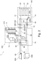
- Fig. 7 is a refrigerant circuit diagram illustrating a configuration of a refrigeration apparatus 300 during a normal refrigeration and cooling operation.
- the shown refrigeration apparatus 300 includes the above described refrigerant circuit 1, the thermal storage unit 100 and the heat exchange unit 200, which are further detailed for explanatory purposes.
- the shown heat exchange unit 200 further includes a subcooling heat exchanger 204, which is located between the first heat exchange unit fluid port 96 and the receiver 201.
- the refrigeration apparatus 300 includes three coolers such as refrigerators and freezers for storing food etc. and three air conditioners (indoor units) for cooling/heating an inside of a room, particularly a show room/shopping room.
- the three indoor units are each provided with one utilization-side heat exchanger 380A - 380C and the three refrigerators are each provided with one additional utilization-side heat exchanger 301A - 301C.
- the shown heat exchange unit 200 further includes a second compressor 310B and a third compressor 310C that are provided parallel to each other and upstream of the above described compressor 10 of the basic configuration.
- the three compressors 310A - 310B build a two-stage compressor system, wherein the second compressor 310B communicates with the additional utilization-side heat exchangers 301A - 301C to build a refrigeration circuit and the third compressor 310C communicates with the utilization-side heat exchangers 380A - 380C to build an air-conditioning circuit.
- the three compressors 310A - 310C can be variable capacity compressors and/or fixed capacity compressors, depending on the requirements of the refrigerant apparatus. All of the three compressors 310A - 310C are hermetic scroll compressors.
- the shown heat exchange unit 200 further includes an injection pipe 206 fluidically connecting a gas side of the receiver 201 with a suction side of the first compressor 10, 310A, wherein the injection pipe 206 is configured to inject intermediate-pressure refrigerant collected by the receiver 201 into the first compressor 10, 310A.
- the injection pipe 206 joins with two high-pressure pipes 207, 208 communicating between high-pressure sides of the second compressor 310B and the third compressor 310C and the suction side of the first compressor 10, 310A, before connecting to a suction side of the first compressor 10, 310A.
- the injection pipe 206 is provided with an expansion device 207, which is preferably located before the connection point of the injection pipe 206 with the high-pressure pipes 207, 208.
- FIG. 7 illustrates the refrigeration apparatus 300 in a normal refrigeration and cooling operation. Accordingly, all three compressors 310A - 310C are turned on, which means, the second compressor 310B draws low pressure refrigerant from the additional utilization-side heat exchangers 301A - 301C of the three coolers and the third compressor 310C draws refrigerant from the utilization-side heat exchanger 380C of one of the three indoor units.
- the two compressors 310B, 310C provide intermediate-pressure refrigerant to the first compressor 310A, which further compresses the refrigerant and discharges high-pressure refrigerant which flows to the heat-source-side heat exchanger 11, which acts as a gas cooler.
- Such refrigerant is cooled by dissipating heat to outdoor air supplied by an outdoor fan.
- the high-pressure refrigerant flowing out from the heat-source-side heat exchanger 11 flows via the first fluid communication pipe 30 to the first switching mechanism 31, particularly the first valve 31A, which is a three-way valve.
- the three-way valve 31A is in a state, in which the first fluid communication pipe 30 is communicating with the third fluid communication pipe 50 and a flow to the second valve 31B is blocked.
- the high-pressure refrigerant flows directly to the expansion device 12, which is an expansion valve, without flowing through the thermal storage 20 or exchanging heat with the thermal storage 20 via the heat exchanger 102.
- the expansion device 12 which is an expansion valve, without flowing through the thermal storage 20 or exchanging heat with the thermal storage 20 via the heat exchanger 102.
- the expansion device 12 Flowing through the expansion device 12, the pressure of the cooled high-pressure refrigerant is reduced, and the refrigerant is changed into intermediate-pressure refrigerant in a gas-liquid two-phase state (subcritical refrigerant).
- the intermediate-pressure refrigerant flows to the receiver 201, a part of the refrigerant, particularly liquid intermediate-pressure refrigerant, flows from the receiver 201 to a first flow path 204A of the subcooling heat exchanger 204.
- the refrigerant flowing into the first flow path 204A is cooled by intermediate-pressure refrigerant flowing through the second flow path 204B, and the degree of subcooling of such refrigerant is increased.
- a part of the so subcooled liquid refrigerant flows through an expansion device 205, particularly a subcooling expansion valve, thereby reducing the pressure of the intermediate-pressure refrigerant further.
- the intermediate-pressure refrigerant flows into the second flow path 204B of the subcooling heat exchanger 204 and is evaporated by absorbing heat from the refrigerant flowing through the first flow path 204A of the subcooling heat exchanger 204.
- the subcooled intermediate-pressure refrigerant flows so as to be branched into two main pipes providing the refrigerant to the refrigeration circuit and the air-conditioning circuit, where the refrigerant is branched again into three pipes providing the utilization-side heat exchangers 380A - 380C of the indoor units and the additional utilization-side heat exchangers 301A - 301C of the coolers with liquid refrigerant.
- the refrigerant flows through an expansion device, particularly an air-conditioning expansion valve or a cooler expansion valve, where the pressure of the intermediate-pressure refrigerant is reduced.
- Such refrigerant flows through the utilization-side heat exchangers and is evaporated by absorbing heat from example room air supplied by an air-conditioning fan of the indoor units.
- the evaporated refrigerant of the utilization-side heat exchangers 380A - 380C of the indoor units is rejoined and flows via a suction pipe back to a suction side of the third compressor 310C.
- the evaporated refrigerant of the additional utilization-side heat exchangers 301A - 301C of the coolers is rejoined and flows via a suction pipe back to a suction side of the second compressor 310B.
- the air-conditioning circuit and the refrigeration circuit are a closed loop.
- the evaporated refrigerant of the subcooling heat exchanger 204 is joined with intermediate-pressure refrigerant discharged from the second compressor 310B and the third compressor 310C and provided to the suction side of the first compressor 310A.
- gas intermediate-pressure refrigerant separated by the receiver 201 from the liquid intermediate-pressure refrigerant of the supercritical refrigerant flows through an expansion device to reduce the pressure to a similar pressure as the pressure of the intermediate-pressure refrigerant discharged by the second compressor 310B and the third compressor 310C.
- Fig. 8 is a refrigerant circuit diagram illustrating the refrigeration apparatus 300 of Fig. 7 during a refrigeration operation using the thermal storage.
- the first switching mechanism 31, in particular the first and second valve, and the second switching valve are set in such a way that the high-pressure refrigerant flowing out from the heat-source-side heat exchanger 11 flows via the first fluid communication pipe 30 into the first and second valve and then into the thermal storage, thereby exchanging heat with the thermal storage 20.
- the high-pressure refrigerant is cooled.
- the high-pressure refrigerant flows via the second switching mechanism via the expansion device 12 back to the receiver 201.
- the pressure of the cooled high-pressure refrigerant is reduced and the refrigerant is changed into intermediate-pressure refrigerant in a gas-liquid two-phase state (supercritical refrigerant).
- a part of the refrigerant flows then from the receiver 201 to the first flow path 204A of the subcooling heat exchanger 204.
- the refrigerant flowing into the first flow path 204A is cooled by intermediate-pressure refrigerant flowing through the second flow path 204B, and the degree of subcooling of such refrigerant is increased.
- a part of the so subcooled liquid refrigerant flows through the expansion device 205 thereby reducing the pressure of the intermediate-pressure refrigerant further.
- the intermediate-pressure refrigerant flows into the second flow path 204B of the subcooling heat exchanger 204 and is evaporated by absorbing heat from the refrigerant flowing through the first flow path 204A of the subcooling heat exchanger 204.
- the subcooled intermediate-pressure refrigerant flows then so as to provide the refrigerant only to the refrigeration circuit and not to the air-conditioning circuit, where the refrigerant is branched again into three pipes providing the additional utilization-side heat exchangers 301A - 301C of the coolers with liquid refrigerant.
- the refrigerant flows through the cooler expansion valve, where the pressure of the intermediate-pressure refrigerant is reduced.
- Such refrigerant flows through the additional utilization-side heat exchangers and is evaporated by absorbing heat from storage room air within the coolers.
- the third compressor 310 is turned off.
- the second compressor 310 draws low pressure refrigerant from the additional utilization-side heat exchangers 301A - 301C of the coolers and provides intermediate-pressure refrigerant via the high-pressure pipe 207 to the first compressor 310A, which further compresses the refrigerant and discharges high-pressure refrigerant which flows to the heat-source-side heat exchanger 11, which acts as a gas cooler.
- Such refrigerant is cooled by dissipating heat to outdoor air supplied by an outdoor fan.
- the high-pressure refrigerant flowing out from the heat-source-side heat exchanger 11 flows then via the first fluid communication pipe 30 back to the first switching mechanism 31, thereby closing the refrigerant circuit.
- Fig. 9 is a refrigerant circuit diagram illustrating the refrigeration apparatus of Fig. 7 during a refrigeration and cooling operation using the thermal storage.
- the refrigeration and cooling operation using the thermal storage is similar to the above with regard to Fig 8 described refrigeration (only) operation using the thermal storage, except that all three compressors 310A to 310C are in use.
- the second compressor 310B draws low pressure refrigerant from the additional utilization-side heat exchangers 301A - 301C of the three coolers and the third compressor 310C draws refrigerant from the utilization-side heat exchanger 380C of one of the three indoor units, which is the provided as intermediate-pressure refrigerant to the first compressor 310A, which further compresses the refrigerant and discharges high-pressure refrigerant which flows to the heat-source-side heat exchanger 11.
- Such refrigerant flows then as described above through the thermal storage 20, the expansion device 12, the receiver 201, the subcooling heat exchanger 204 and is then branched into the two main pipes providing the refrigerant to the refrigeration circuit and the air-conditioning circuit, closing the refrigerant circuit.
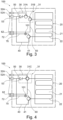
- Fig. 10 is a refrigerant circuit diagram illustrating the refrigeration apparatus of Fig. 7 during an only charging operation of the thermal storage.
- the second compressor 310B is turned off.
- the third compressor 310C draws the refrigerant directly from the thermal storage 20 and provides intermediate-pressure refrigerant to the first compressor which compresses the refrigerant further and discharges high-pressure refrigerant which flows to the heat-source-side heat exchanger 11, which acts as a gas cooler.
- the high-pressure refrigerant flowing out from the heat-source-side heat exchanger 11 flows then via the first fluid communication pipe 30 to the first switching mechanism 31.
- the first valve 31A is set in such a manner that the high-pressure refrigerant flows as described above with Fig. 7 directly to the expansion device 12.
- the intermediate-pressure refrigerant in a gas-liquid two-phase state flows to the receiver 201 and from there liquid intermediate-pressure refrigerant flows then to the first flow path 204A of the subcooling heat exchanger 204.
- the refrigerant flowing into the first flow path 204A is cooled by intermediate-pressure refrigerant flowing through the second flow path 204B, and the degree of subcooling of such refrigerant is increased.
- the subcooled intermediate-pressure refrigerant flows then via the second valve 31B back to the thermal storage 20 and by flowing through the thermal storage 20 cools the thermal storage 20, in particular the thermal storage material, thereby charges the thermal storage with cold.
- Fig. 11 is a refrigerant circuit diagram illustrating the refrigeration apparatus of Fig. 7 during a refrigeration operation while charging the thermal storage.
- the refrigeration operation while charging the thermal storage is similar to the above with regard to Fig. 10 described only charging operation of the thermal storage, except that all three compressors 310A - 310C are in use and that the second compressor 310B connects the additional utilization-side heat exchangers 301A - 301C of the coolers to the refrigerant circuit 1.
- the thermal storage 20 can be charged while performing a refrigeration operation.
- Fig. 12 is a refrigerant circuit diagram illustrating a configuration of another refrigeration apparatus 300 having a capacity increasing unit 320.
- the refrigerant apparatus 300 of the second embodiment mostly corresponds to the refrigerant apparatus of the first embodiment described with regard to Fig. 7 .
- the thermal storage unit 100 instead of being provided with the thermal storage unit 100, the two connecting pipes connecting the second heat exchanger unit fluid port 32B and the third heat exchanger unit fluid port 52B have an open end. Meaning, the unit connected via the second and third heat exchanger unit fluid ports 32B and 52B with the refrigerant apparatus 300, in particular with the heat exchanger unit 200, is not shown.
- the thermal storage unit 100 instead of the thermal storage unit 100 also a heat exchanger, particularly a plate heat exchanger, a capacity increasing unit or a combi unit including a thermal storage unit and a capacity increasing unit can be connected to the heat exchanger unit 200.
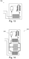
- Fig. 13 is a refrigerant circuit diagram illustrating a capacity increasing unit 320.
- the capacity increasing unit 320 is basically an independent refrigerant circuit that can be added to or connected with the refrigerant apparatus 300, in order to increase the refrigeration and cooling capacity of the refrigerant apparatus 300.
- the capacity increasing unit 320 includes a heat exchanger, a compressor and an expansion device which build a closed refrigerant circuit.
- the heat exchanger is configured to exchange heat with the heat exchanger unit 200. Therefore, the heat exchanger can be connected with the second and third heat exchanger unit fluid ports 32B and 52B.
- the capacity increasing unit 320 is provided with a heat-source-side heat exchanger that cools down the refrigerant flowing there through by dissipating heat to outdoor air supplied by an outdoor fan.
- Fig. 14 is a refrigerant circuit diagram illustrating a combi unit 330 having a capacity increasing unit 320 and a thermal storage unit.
- the capacity increasing unit 320 includes a heat exchanger, a compressor and an expansion device which build a closed refrigerant circuit.
- the thermal storage unit is arranged between the heat exchanger unit 200 and the thermal storage unit.
- the combi unit 330 additionally includes a circulating pump that circulates a refrigerant or a coolant like water, cooled by the capacity increasing unit through the thermal storage unit, in order to charge the thermal storage unit with thermal energy, particularly cold.
- the thermal storage unit is provided with a heat exchanger that is used to exchange heat with the refrigerant circuit of the refrigerant apparatus 300, in particular with the heat exchanger unit 200.
- the capacity increasing unit may include a closed refrigerant circuit including a heat exchanger, a compressor, a heat-source-side heat exchanger cooled by a fan and an expansion device, wherein the heat exchanger exchanges heat with the heat exchange unit.
- the combi unit may include a capacity increasing unit, comprising a closed refrigerant circuit including a heat exchanger, a compressor, a heat-source-side heat exchanger cooled by a fan and an expansion device, and a thermal storage unit comprising a heat exchanger, a thermal storage, including a thermal storage material, particularly a phase changing material (PCM), and a circulating pump, wherein the heat exchanger exchanges heat with the heat exchange unit.
- a capacity increasing unit comprising a closed refrigerant circuit including a heat exchanger, a compressor, a heat-source-side heat exchanger cooled by a fan and an expansion device
- a thermal storage unit comprising a heat exchanger, a thermal storage, including a thermal storage material, particularly a phase changing material (PCM), and a circulating pump, wherein the heat exchanger exchanges heat with the heat exchange unit.
- PCM phase changing material
Description
- The present invention relates to a refrigerant circuit for cooling and/or heating purposes.
- In particular, the invention relates to a refrigerant circuit for a refrigeration apparatus with a thermal storage particularly a thermal storage with a phase changing material (PCM). Even more particular, the invention relates to a refrigerant circuit for a refrigeration apparatus with a thermal storage using CO2 as a refrigerant.
- As described in
EP 2 402 681 A1 , conventionally, a refrigerating apparatus has been known, which includes a refrigerant circuit performing a refrigeration cycle. The refrigerating apparatus of this type has been widely used for coolers such as refrigerators and freezers for storing food etc. and air conditioners for cooling/heating an inside of a room. - Moreover,
EP 2 844 924 B1 discloses an air-conditioning system comprising: a chiller system including a compressor, a condenser, an expansion device and an evaporator, a phase change material in thermal communication with the condenser, an actuator coupled to the phase change material; and a controller providing a trigger signal to the actuator to initiate changing the phase change material from a supercooled state to a solid state, wherein the phase change material includes a coolant supply line in thermal communication with the phase change material and the coolant supply line is coupled to the chiller system. The phase change material is selected so that the phase change material transitions from liquid to solid when cooling demand on the chiller system is low or non-existent. This may occur in the evening, when ambient temperatures are lower. During the day, the solid or frozen phase change material absorbs energy from the condenser, improving the efficiency of the condenser when the chiller system is running and increasing efficiency and capacity of the chiller system. - The air-conditioning system described in
EP 2 844 924 B1 aims to provide a system that is capable of balancing cooling demand by using a phase change material as a heat buffer between the condenser and the ambient air temperature. During the day, the phase change material absorbs the heat from the condenser and release it to the outside air. Due to its thermal capacity and the latent heat release, the phase change material will heat up slower than air and thus result in higher energy efficiency. At night, the phase change material is cooled down faster by the fresher air temperature using the fan only. - However, active cooling of the phase change material with the fan is inefficient, therefore, said system is particularly not suitable for regions with warmer climates, where air temperatures at night remain high. Moreover, the described system is not able to realize big improvements with regard to energy efficiency but will "flatten out" the energy consumption pattern due to the thermal response time of the phase change material. This is in particular true, since the active cooling of the phase change material also causes heating of the condenser, as the condenser is in thermal communication with the phase change material, and no control of the use of the phase change material is possible.
- Additionally, fluorocarbon has been conventionally used as a refrigerant in refrigeration systems. However, following the Montreal Protocol in 1987 and the Kyoto Protocol in 1997, artificially developed substitute chlorofluorocarbons, whose ozone depletion potential is low, have become commonly used as refrigerants. Yet, in recent years, the development of technology using even more environmentally friendly substitutes, particularly using natural refrigerants such as carbon dioxide, ammonia, hydrocarbons (isobutene, propane, etc.), water and air, has progressed. These natural refrigerants are materials that have the property that, when compared with the aforementioned chlorofluorocarbons and substitute chlorofluorocarbons, their GWP (Global Warming Potential) value is extremely low.
- Among these, carbon dioxide is known as a material whose ozone depletion potential is zero, whose global warming potential is also much lower in comparison to conventional refrigerants, which has no toxicity, is non-flammable, and whose efficiency in creating a high temperature is good among natural refrigerants, and from environmental/energy aspects and safety aspects, carbon dioxide is garnering attention as a refrigerant in air conditioners.
- However, carbon dioxide (CO2) performs at high outside temperatures with a lower efficiency than fluorinated refrigerants. Accordingly, on an annual base the performance of an air conditioner system using CO2 as a refrigerant is lower compared to fluorinated refrigerants, particularly in warmer climates.
- Other related art may be found in
EP 3 242 096 A1 being directed to a regenerative air conditioner comprising a refrigerant circuit to which a compressor section, an outdoor heat exchanger and an indoor heat exchanger are connected; and a thermal storage section in which heat is exchanged between the refrigerant in the refrigerant circuit and a thermal storage medium.EP 2 242 096 A1 also shows a thermal storage unit according to the preamble of claim 1. - In view of the above, there is the desire to provide a refrigerant circuit for a refrigeration apparatus with a thermal storage, which is using carbon dioxide (CO2) as refrigerant, allowing the storage of thermal energy, particularly cold, for example when outside temperatures are low, preferably during the night, and use the thermal energy during peak temperatures during the day when transcritical conditions occur or during peak demand, in order to substantially prevent a decrease in cooling efficiency, which is particularly due to the use of a natural refrigerant like carbon dioxide, while ensuring a high cooling capacity and providing flexibility with regard to charging the thermal storage with cold. Additionally, if circumstances require it or allow it, the provided refrigerant circuit should also be able to store thermal energy, particularly cold, even during peak temperatures when for example much/excess PV power (CO2 neutral energy generation) is available.
- According to the invention this aim is achieved by a thermal storage unit as defined in claim 1 and used for a refrigeration apparatus using CO2 as refrigerant. Preferred embodiments of the thermal storage unit are the subject of the dependent claims.
- As regards the term "natural" concerning the "natural refrigerant", the term defines in the present disclosure refrigerants that occur naturally.
- Moreover, in the present disclosure the term "fluid" concerning the "fluid communication pipe(s)" and the "fluid port(s)" is used as the fluid, particularly the CO2, flowing there through is in a supercritical condition (supercritical fluid), which means, the fluid is at a temperature and pressure above its critical point, where distinct liquid and gas phases do not exist. Accordingly, the "fluid communication pipe(s)" and the "fluid port(s)" are common "liquid communication pipe(s)" and "liquid port(s)", only emphasizing that the fluid flowing there through is in a supercritical condition.
- The thermal storage unit may further include a refrigerant heat exchange pipe disposed inside the thermal storage, particularly inside the thermal storage material, wherein the first switching mechanism communicates with one side of the refrigerant heat exchange pipe and the second switching mechanism communicates with the other end of the refrigerant heat exchange pipe.
- Moreover, the first switching mechanism includes: a first valve, which is a three-way valve, communicating among the second thermal storage unit fluid port, the third thermal storage unit fluid port and the thermal storage, and preferably a second valve, which is a three-way valve and located/provided between the first valve and the thermal storage, communicating among the first valve, the thermal storage and the thermal storage unit gas port, wherein the first switching mechanism preferably further comprises a check valve that is located/provided between the first valve and the third thermal storage unit fluid port.
- Alternatively, the first switching mechanism includes a first valve, which may be a four-way valve, communicating among the second thermal storage unit fluid port, the thermal storage, the thermal storage unit gas port and the third thermal storage unit fluid port, wherein the first switching mechanism further includes a check valve that stops a backflow from the third thermal storage unit fluid port to the first valve.
- The second switching mechanism may be a valve, which is a three-way valve, communicating among the first thermal storage unit fluid port, the third thermal storage unit fluid port and the thermal storage, wherein preferably an expansion device is located/provided between the second switching mechanism and the first thermal storage unit fluid port.
- An expansion device is located/provided on the fourth thermal storage unit fluid communication pipe.
- Moreover, a check valve is located/provided on the third thermal storage unit fluid communication pipe and stops a backflow from the third thermal storage unit fluid port to the first switching mechanism, particularly a/the first valve.
- The second thermal storage unit fluid communication pipe may be connected with the third thermal storage unit fluid communication pipe between the third thermal storage unit fluid port and the check valve.
- The thermal storage unit may further include a thermal storage unit gas communication pipe communicating between the thermal storage unit gas port and the first switching mechanism, particularly a/the second valve.
- Furthermore, the thermal storage material is a phase changing material (PCM) from the group: organic PCMs like bio-based, paraffin, carbohydrate or lipid derived, or water.
- The thermal storage unit may further include a heat exchanger, particularly a plate heat exchanger, which is on one side communicating with the first switching mechanism and the second switching mechanism and on the other side with the one side of the thermal storage and the other side of the thermal storage.
- Furthermore, the thermal storage unit may further include a circulating pump that is located/provided on the first thermal storage unit fluid communication pipe or the second thermal storage unit fluid communication pipe, between the heat exchanger and the thermal storage.
- The thermal storage unit may further include a water circuit, a refrigerant to phase change material (PCM) circuit or a refrigerant to water to phase change material (PCM) circuit having a heat exchanger, particularly a plate heat exchanger, and a circulating pump.
- The thermal storage unit is a unit that can be used for a refrigerant circuit. Therefore, the further features disclosed in connection with the above description of the thermal storage unit may also be applied to the refrigerant circuit. The same applies vice versa for the thermal storage unit.
- A more complete appreciation of the present invention and many of the attendant advantages thereof will be readily obtained as the same becomes better understood by reference to the following detailed description when considered in connection with the accompanying drawings.
-
Fig. 1 shows a conventional air-conditioning system having a supercooled phase change material (PCM); -
Fig. 2 is a refrigerant circuit diagram illustrating a configuration of a refrigerant circuit; -
Fig. 3 is a refrigerant circuit diagram illustrating a configuration of a thermal storage unit of a fist embodiment of the invention; -
Fig. 4 is a refrigerant circuit diagram illustrating a configuration of a thermal storage unit of a second embodiment of the invention; -
Fig. 5 is a refrigerant circuit diagram illustrating a configuration of a thermal storage unit of a third embodiment of the invention; -
Fig. 6 is a refrigerant circuit diagram illustrating a configuration of a heat exchange unit; -
Fig. 7 is a refrigerant circuit diagram illustrating a configuration of a refrigeration apparatus during a normal refrigeration and cooling operation; -
Fig. 8 is a refrigerant circuit diagram illustrating the refrigeration apparatus ofFig. 7 during a refrigeration operation using the thermal storage; -
Fig. 9 is a refrigerant circuit diagram illustrating the refrigeration apparatus ofFig. 7 during a refrigeration and cooling operation using the thermal storage; -
Fig. 10 is a refrigerant circuit diagram illustrating the refrigeration apparatus ofFig. 7 during an only charging operation of the thermal storage; -
Fig. 11 is a refrigerant circuit diagram illustrating the refrigeration apparatus ofFig. 7 during a refrigeration operation while charging the thermal storage; -
Fig. 12 is a refrigerant circuit diagram illustrating a configuration of another refrigeration apparatus having a capacity increasing unit; -
Fig. 13 is a refrigerant circuit diagram illustrating a capacity increasing unit; and -
Fig. 14 is a refrigerant circuit diagram illustrating a combi unit having a capacity increasing unit and a thermal storage unit. - Several embodiments of the present invention will now be explained with reference to the drawings. It will be apparent to those skilled in the field of air-conditioning from this disclosure that the following description of the embodiments is provided for illustration only and not for the purpose of limiting the disclosure as defined by the appended claims.
-
Figure 1 shows a conventional air-conditioning system 100 having a supercooled phase change material (PCM). A chiller system includes acompressor 110, afirst heat exchanger 112, anexpansion device 114 and asecond heat exchanger 116. Thefirst heat exchanger 112 may be used as a condenser coil and may be located outside of a building or space to be conditioned. Thesecond heat exchanger 116 may be used as an evaporator coil. As known in the art, refrigerant is subjected to a vapor compression cycle throughcompressor 110,condenser 112,expansion device 114 andevaporator 116. Heat is absorbed atevaporator 116 and heat is discharged atcondenser 112. - The system of
Fig. 1 may be a water chiller system.Evaporator 116 is in thermal communication with a heat exchanger 118 (e.g., a coil) that carries a fluid coolant, e.g., water. Asupply pump 120 circulates coolant fromheat exchanger 118 cooled byevaporator 116 to asupply valve 122.Supply valve 22 supplies chilled water to a local zone terminal where a fan draws air over a coil to chill a space as known in the art. Areturn valve 124 receives fluid returned from the local zone terminal and provides the return fluid toheat exchanger 118. - Moreover, the
condenser coil 112 as shown inFig. 1 is in thermal communication with aphase change material 126. Afan 128 draws air through thephase change material 126 to aid in cooling thephase change material 126. Acontroller 132 then initiates the transition of thephase change material 126 from supercooled liquid to solid. Anactuator 130 is used to initiate the transition of thephase change material 126 from supercooled liquid to solid when thephase change material 126 is in a supercooled state. Theactuator 130 includes a thermoelectric cooler for freezing thephase change material 126.Controller 132 receives a phase change material temperature signal from a phasechange material sensor 134 and an ambient temperature signal from anambient temperature sensor 136. - The
phase change material 126 is selected so that the phase change material transitions from liquid to solid when cooling demand on the chiller system is low or non-existent. This may occur in the evening, when ambient temperatures are low. During the day, the solid or frozenphase change material 126 absorbs energy from thecondenser 112 when the chiller system is running and increasing efficiency and capacity of the chiller system. - Furthermore,
Fig. 2 is a refrigerant circuit 1 diagram illustrating a configuration of a refrigerant circuit The shown refrigerant circuit uses CO2 as refrigerant and includes onecompressor 10, a heat-source-side heat exchanger of an outdoor unit of a so called "Conveni-Pack", including usually coolers such as refrigerators and freezers for storing food etc. and air conditioners (indoor units) for cooling/heating an inside of a room, particularly a show room/shopping room. In the shown refrigerant circuit only one indoor unit and one cooler are illustrated as example, but the refrigerant circuit can naturally include several coolers and air conditioners. The shown refrigerant circuit further includes athermal storage unit 100 and aheat exchange unit 200, which will be explained later in more detail. Thethermal storage unit 100 includes athermal storage 20 including/accumulating athermal storage material 21, which is a phase changing material (PCM). The shown refrigerant circuit further includes a firstfluid communication pipe 30 that connects a fluid side of the heat-source-side heat exchanger 11 with one side of thethermal storage 20 and a secondfluid communication pipe 40 that connects theexpansion device 12 and the other side of thethermal storage 20. - In this regard, the term "connect" is used in the present disclosure to define that two entities, for example the "one side of the thermal storage" and the "thermal storage", are connected with each other by a connecting means such as a "liquid pipe" or a "gas pipe" in such a manner that a fluid like a refrigerant can be liquid-tight and gas-tight transferred/exchanged/flow from one entity to the other one. In other words, the connecting means provides a fluidic connection.
- The refrigerant circuit 1 further includes a
first switching mechanism 31, which is located on the firstfluid communication pipe 30 and fluidically connects the heat-source-side heat exchanger 11, thethermal storage 20, a thirdfluid communication pipe 50 and a firstgas communication pipe 60 with each other, wherein the thirdfluid communication pipe 50 is fluidically connecting to theexpansion device 12 and the firstgas communication pipe 60 is fluidically connecting to a suction side of thecompressor 10. - The shown refrigerant circuit 1 further includes a
second switching mechanism 41 located on the secondfluid communication pipe 40 and fluidically connects thethermal storage 20, theexpansion device 12 and a fourthfluid communication pipe 70 with each other, wherein the fourthfluid communication pipe 70 is fluidically connecting to a utilization-side heat exchanger 80A. -
Fig. 2 also shows that the refrigerant circuit 1 further comprises areceiver 201, which is located on the thirdfluid communication pipe 50, between theexpansion device 12 and the utilization-side heat exchanger 80A, wherein thereceiver 201 is configured to separate the refrigerant coming from the expansion device in a subcritical state into liquid refrigerant and gas refrigerant. - The shown refrigerant circuit 1 also indicates that the refrigerant circuit 1 can further include an additional utilization-
side heat exchanger 80B communicating on its liquid side with theexpansion device 12 via thereceiver 201 and on its gas side with thecompressor 10. - As illustrated in
Fig. 2 , the utilization-side heat exchanger 80A can be a heat exchanger of an air-conditioner, particularly of an indoor unit, and the additional utilization-side heat exchanger 80B can be a heat exchanger of a cooler such as a refrigerator or a freezer. -
Fig. 3 is a refrigerant circuit diagram illustrating a configuration of a thermal storage unit of a fist embodiment. The shownthermal storage unit 100 is part of the above described refrigerant circuit 1, wherein the switching mechanism 1 is configured according to a first alternative. - The shown
thermal storage unit 100 includes thethermal storage 20 including the above describedthermal storage material 21, which is a phase changing material (PCM), a thermal storageunit gas port 62 communicating to the utilization-side heat exchanger 80A, disposed outside thethermal storage unit 100, a first thermal storageunit fluid port 72 communicating to the utilization-side heat exchanger 80A, a second thermal storageunit fluid port 32A communicating to the heat-source-side heat exchanger 11, disposed outside thethermal storage unit 100, and a third thermal storageunit fluid port 52A communicating to theexpansion device 12 disposed outside thethermal storage unit 100. - The shown
thermal storage unit 100 further includes thefirst switching mechanism 31 communicating among the second thermal storageunit fluid port 32A, the third thermalstorage fluid port 52A, the thermal storageunit gas port 62 and one side of thethermal storage 20, and thesecond switching mechanism 41 communicating among the first thermal storageunit fluid port 72, the third thermal storageunit fluid port 52A and the other side of thethermal storage 20. - Moreover, the in
Fig. 3 shownthermal storage unit 100 further includes a refrigerantheat exchange pipe 22 that is disposed inside thethermal storage 20, particularly inside thethermal storage material 21. Thefirst switching mechanism 31 is fluidically connected with one side of the refrigerantheat exchange pipe 22 and thesecond switching mechanism 41 is fluidically connected with the other end of the refrigerantheat exchange pipe 22. - According to the shown embodiment, the
first switching mechanism 31 includes: afirst valve 31A, which is a three-way valve, communicating among the second thermal storageunit fluid port 32A, the third thermal storageunit fluid port 52A and thethermal storage 20, and asecond valve 31B, which is a three-way valve and located between thefirst valve 31A and thethermal storage 20, communicating among thefirst valve 31A, thethermal storage 20 and the thermal storageunit gas port 62. - Between the
first valve 31A and the third thermal storageunit fluid port 52A is acheck valve 31A provided that stops a backflow from the third thermal storageunit fluid port 52A to thefirst valve 31A. - The shown
second switching mechanism 41 is a valve, which is a three-way valve, fluidically connecting the first thermal storageunit fluid port 72, the third thermal storageunit fluid port 52A and thethermal storage 20 with each other, wherein anexpansion device 101 is located between thesecond switching mechanism 41 and the first thermal storageunit fluid port 72. - The second thermal storage unit
fluid communication pipe 40 is connected with the third thermal storage unitfluid communication pipe 50 between the third thermal storageunit fluid port 52A and thecheck valve 53. A thermal storage unitgas communication pipe 60 fluidically connects the thermal storageunit gas port 62 and thefirst switching mechanism 31, particularly thesecond valve 31B, with each other. -
Fig. 4 is a refrigerant circuit diagram illustrating a configuration of thethermal storage unit 100 according to a second embodiment, particularly an alternative configuration. The illustrated refrigerant circuit corresponds to the refrigerant circuit disclosed inFig. 3 except the configuration of the first switching mechanism. In the shown alternative configuration, the firstfirst valve 31A is a four-way valve that fluidically connects the second thermal storageunit fluid port 32A, thethermal storage 20, the thermal storageunit gas port 62 and the third thermal storageunit fluid port 52A. -
Fig. 5 is a refrigerant circuit diagram illustrating a configuration of athermal storage unit 100 according to a third embodiment, particularly a third alternative. The shown alternative does not use the above described refrigerantheat exchange pipe 22, instead uses aheat exchanger 102. As shown, theheat exchanger 102 is preferably a plate heat exchanger, which is on one side communicating with thefirst switching mechanism 31 and thesecond switching mechanism 41 and on the other side with the one side of thethermal storage 20 and the other side of thethermal storage 20. - Additionally, the
thermal storage unit 100 includes a circulatingpump 103 that is located on the second thermal storage unitfluid communication pipe 40, between theheat exchanger 102 and thethermal storage 20. Accordingly, the thermal storage has a closed loop, particularly using water as coolant. The circulating pump circulates the coolant through thethermal storage 20, thereby the coolant exchanges heat with thethermal storage material 21 of the thermal storage, and then to theheat exchanger 102, where the coolant again exchanges heat with the refrigerant of the refrigerant circuit 1. Hence, the circulatingpump 103 is able to control the amount of thermal energy exchanged between thethermal storage 20, particularly thethermal storage material 21, and the refrigerant of the refrigerant circuit 1. - The in connection with
Fig. 5 described embodiment can be combined with both alternatives with regard to the first switching mechanism, namely a first three-way valve or four-way valve 31A. -
Fig. 6 is a refrigerant circuit diagram illustrating a configuration of aheat exchange unit 200 The shownheat exchange unit 200 includes thecompressor 10, the heat-source-side heat exchanger 11 theexpansion device 12, a heat exchangeunit gas port 92 communicating to the utilization-side heat exchanger 80A disposed outside theheat exchange unit 200, a first heat exchangeunit fluid port 96 communicating to the utilization-side heat exchanger 80A, a second heat exchangeunit fluid port 32B communicating to the heat-source-side heat exchanger 11, a third heat exchangeunit fluid port 52B communicating to theexpansion device 12. The shown second heat exchangeunit fluid port 32B is fluidically connected to the above describedthermal storage unit 100 disposed outside theheat exchange unit 200 and the third heat exchangeunit fluid port 52B is also fluidically connected to thethermal storage unit 100. - The shown
heat exchange unit 200 further includes a heat exchange unitgas communication pipe 90 communicating between the heat exchangeunit gas port 92 and the at least onecompressor 10, a first heat exchange unitfluid communication pipe 30 communicating between the second heat exchangeunit fluid port 32B and the heat-source-side heat exchanger 11, and a second heat exchange unitfluid communication pipe 50 communicating between the third heat exchangeunit fluid port 52B and the first heat exchangeunit fluid port 96. - The
expansion device 12 is located on the second heat exchange unitfluid communication pipe 50, between the first heat exchangeunit fluid port 96 and the third heat exchangeunit fluid port 52B. - The shown
heat exchange unit 200 further includes the above describedreceiver 201, which is located on the second heat exchange unitfluid communication pipe 50, between the first heat exchangeunit fluid port 96 and theexpansion device 12, wherein thereceiver 201 is configured to separate liquid refrigerant and gas refrigerant. Theheat exchange unit 200 further includes a fourth heat exchangeunit fluid port 203 fluidically connecting theexpansion device 12 and the additional utilization-side heat exchanger 80B disposed outside theheat exchange unit 200. - The shown
heat exchange unit 200 further includes a third heat exchange unitfluid communication pipe 202 fluidically connecting the fourth heat exchangeunit fluid port 203 with theexpansion device 12 and is connected with the second heat exchange unitfluid communication pipe 50 between the first heat exchangeunit fluid port 96 and thereceiver 201. -
Fig. 7 is a refrigerant circuit diagram illustrating a configuration of arefrigeration apparatus 300 during a normal refrigeration and cooling operation. The shownrefrigeration apparatus 300 includes the above described refrigerant circuit 1, thethermal storage unit 100 and theheat exchange unit 200, which are further detailed for explanatory purposes. - The shown
heat exchange unit 200 further includes asubcooling heat exchanger 204, which is located between the first heat exchangeunit fluid port 96 and thereceiver 201. Therefrigeration apparatus 300 includes three coolers such as refrigerators and freezers for storing food etc. and three air conditioners (indoor units) for cooling/heating an inside of a room, particularly a show room/shopping room. The three indoor units are each provided with one utilization-side heat exchanger 380A - 380C and the three refrigerators are each provided with one additional utilization-side heat exchanger 301A - 301C. - Additionally, the shown
heat exchange unit 200 further includes asecond compressor 310B and athird compressor 310C that are provided parallel to each other and upstream of the above describedcompressor 10 of the basic configuration. In this way, the threecompressors 310A - 310B build a two-stage compressor system, wherein thesecond compressor 310B communicates with the additional utilization-side heat exchangers 301A - 301C to build a refrigeration circuit and thethird compressor 310C communicates with the utilization-side heat exchangers 380A - 380C to build an air-conditioning circuit. The threecompressors 310A - 310C can be variable capacity compressors and/or fixed capacity compressors, depending on the requirements of the refrigerant apparatus. All of the threecompressors 310A - 310C are hermetic scroll compressors. - The shown
heat exchange unit 200 further includes aninjection pipe 206 fluidically connecting a gas side of thereceiver 201 with a suction side of thefirst compressor injection pipe 206 is configured to inject intermediate-pressure refrigerant collected by thereceiver 201 into thefirst compressor Fig. 7 , theinjection pipe 206 joins with two high-pressure pipes second compressor 310B and thethird compressor 310C and the suction side of thefirst compressor first compressor - Additionally, the
injection pipe 206 is provided with anexpansion device 207, which is preferably located before the connection point of theinjection pipe 206 with the high-pressure pipes - As already mentioned above,
Fig. 7 illustrates therefrigeration apparatus 300 in a normal refrigeration and cooling operation. Accordingly, all threecompressors 310A - 310C are turned on, which means, thesecond compressor 310B draws low pressure refrigerant from the additional utilization-side heat exchangers 301A - 301C of the three coolers and thethird compressor 310C draws refrigerant from the utilization-side heat exchanger 380C of one of the three indoor units. Via the high-pressure pipes compressors first compressor 310A, which further compresses the refrigerant and discharges high-pressure refrigerant which flows to the heat-source-side heat exchanger 11, which acts as a gas cooler. Such refrigerant is cooled by dissipating heat to outdoor air supplied by an outdoor fan. The high-pressure refrigerant flowing out from the heat-source-side heat exchanger 11 flows via the firstfluid communication pipe 30 to thefirst switching mechanism 31, particularly thefirst valve 31A, which is a three-way valve. The three-way valve 31A is in a state, in which the firstfluid communication pipe 30 is communicating with the thirdfluid communication pipe 50 and a flow to thesecond valve 31B is blocked. Hence, the high-pressure refrigerant flows directly to theexpansion device 12, which is an expansion valve, without flowing through thethermal storage 20 or exchanging heat with thethermal storage 20 via theheat exchanger 102. Flowing through theexpansion device 12, the pressure of the cooled high-pressure refrigerant is reduced, and the refrigerant is changed into intermediate-pressure refrigerant in a gas-liquid two-phase state (subcritical refrigerant). - Subsequently, the intermediate-pressure refrigerant flows to the
receiver 201, a part of the refrigerant, particularly liquid intermediate-pressure refrigerant, flows from thereceiver 201 to a first flow path 204A of thesubcooling heat exchanger 204. The refrigerant flowing into the first flow path 204A is cooled by intermediate-pressure refrigerant flowing through the second flow path 204B, and the degree of subcooling of such refrigerant is increased. A part of the so subcooled liquid refrigerant flows through anexpansion device 205, particularly a subcooling expansion valve, thereby reducing the pressure of the intermediate-pressure refrigerant further. The intermediate-pressure refrigerant flows into the second flow path 204B of thesubcooling heat exchanger 204 and is evaporated by absorbing heat from the refrigerant flowing through the first flow path 204A of thesubcooling heat exchanger 204. - The subcooled intermediate-pressure refrigerant flows so as to be branched into two main pipes providing the refrigerant to the refrigeration circuit and the air-conditioning circuit, where the refrigerant is branched again into three pipes providing the utilization-
side heat exchangers 380A - 380C of the indoor units and the additional utilization-side heat exchangers 301A - 301C of the coolers with liquid refrigerant. Before entering the utilization-side heat exchangers 380A - 380C, 301A - 301C, the refrigerant flows through an expansion device, particularly an air-conditioning expansion valve or a cooler expansion valve, where the pressure of the intermediate-pressure refrigerant is reduced. Such refrigerant flows through the utilization-side heat exchangers and is evaporated by absorbing heat from example room air supplied by an air-conditioning fan of the indoor units. - The evaporated refrigerant of the utilization-
side heat exchangers 380A - 380C of the indoor units is rejoined and flows via a suction pipe back to a suction side of thethird compressor 310C. The evaporated refrigerant of the additional utilization-side heat exchangers 301A - 301C of the coolers is rejoined and flows via a suction pipe back to a suction side of thesecond compressor 310B. Thereby, the air-conditioning circuit and the refrigeration circuit are a closed loop. The evaporated refrigerant of thesubcooling heat exchanger 204 is joined with intermediate-pressure refrigerant discharged from thesecond compressor 310B and thethird compressor 310C and provided to the suction side of thefirst compressor 310A. - Additionally, gas intermediate-pressure refrigerant separated by the
receiver 201 from the liquid intermediate-pressure refrigerant of the supercritical refrigerant, flows through an expansion device to reduce the pressure to a similar pressure as the pressure of the intermediate-pressure refrigerant discharged by thesecond compressor 310B and thethird compressor 310C. -
Fig. 8 is a refrigerant circuit diagram illustrating therefrigeration apparatus 300 ofFig. 7 during a refrigeration operation using the thermal storage. In this operation, thefirst switching mechanism 31, in particular the first and second valve, and the second switching valve are set in such a way that the high-pressure refrigerant flowing out from the heat-source-side heat exchanger 11 flows via the firstfluid communication pipe 30 into the first and second valve and then into the thermal storage, thereby exchanging heat with thethermal storage 20. Flowing though thethermal storage 20 the high-pressure refrigerant is cooled. After leaving thethermal storage 20 the high-pressure refrigerant flows via the second switching mechanism via theexpansion device 12 back to thereceiver 201. By flowing through theexpansion device 12, the pressure of the cooled high-pressure refrigerant is reduced and the refrigerant is changed into intermediate-pressure refrigerant in a gas-liquid two-phase state (supercritical refrigerant). - As described above, a part of the refrigerant, particularly liquid intermediate-pressure refrigerant, flows then from the
receiver 201 to the first flow path 204A of thesubcooling heat exchanger 204. The refrigerant flowing into the first flow path 204A is cooled by intermediate-pressure refrigerant flowing through the second flow path 204B, and the degree of subcooling of such refrigerant is increased. A part of the so subcooled liquid refrigerant flows through theexpansion device 205 thereby reducing the pressure of the intermediate-pressure refrigerant further. The intermediate-pressure refrigerant flows into the second flow path 204B of thesubcooling heat exchanger 204 and is evaporated by absorbing heat from the refrigerant flowing through the first flow path 204A of thesubcooling heat exchanger 204. - The subcooled intermediate-pressure refrigerant flows then so as to provide the refrigerant only to the refrigeration circuit and not to the air-conditioning circuit, where the refrigerant is branched again into three pipes providing the additional utilization-
side heat exchangers 301A - 301C of the coolers with liquid refrigerant. Before entering the additional utilization-side heat exchangers 301A - 301C, the refrigerant flows through the cooler expansion valve, where the pressure of the intermediate-pressure refrigerant is reduced. Such refrigerant flows through the additional utilization-side heat exchangers and is evaporated by absorbing heat from storage room air within the coolers. - Since the cooling operation is turned off, only the
second compressor 310B and thefirst compressor 310A are in use, the third compressor 310 is turned off. Hence, the second compressor 310 draws low pressure refrigerant from the additional utilization-side heat exchangers 301A - 301C of the coolers and provides intermediate-pressure refrigerant via the high-pressure pipe 207 to thefirst compressor 310A, which further compresses the refrigerant and discharges high-pressure refrigerant which flows to the heat-source-side heat exchanger 11, which acts as a gas cooler. Such refrigerant is cooled by dissipating heat to outdoor air supplied by an outdoor fan. The high-pressure refrigerant flowing out from the heat-source-side heat exchanger 11 flows then via the firstfluid communication pipe 30 back to thefirst switching mechanism 31, thereby closing the refrigerant circuit. -
Fig. 9 is a refrigerant circuit diagram illustrating the refrigeration apparatus ofFig. 7 during a refrigeration and cooling operation using the thermal storage. The refrigeration and cooling operation using the thermal storage is similar to the above with regard toFig 8 described refrigeration (only) operation using the thermal storage, except that all threecompressors 310A to 310C are in use. Hence, thesecond compressor 310B draws low pressure refrigerant from the additional utilization-side heat exchangers 301A - 301C of the three coolers and thethird compressor 310C draws refrigerant from the utilization-side heat exchanger 380C of one of the three indoor units, which is the provided as intermediate-pressure refrigerant to thefirst compressor 310A, which further compresses the refrigerant and discharges high-pressure refrigerant which flows to the heat-source-side heat exchanger 11. - Such refrigerant flows then as described above through the
thermal storage 20, theexpansion device 12, thereceiver 201, thesubcooling heat exchanger 204 and is then branched into the two main pipes providing the refrigerant to the refrigeration circuit and the air-conditioning circuit, closing the refrigerant circuit. -
Fig. 10 is a refrigerant circuit diagram illustrating the refrigeration apparatus ofFig. 7 during an only charging operation of the thermal storage. - In this operation only the
third compressor 310C and thefirst compressor 310A are in use, thesecond compressor 310B is turned off. Thethird compressor 310C draws the refrigerant directly from thethermal storage 20 and provides intermediate-pressure refrigerant to the first compressor which compresses the refrigerant further and discharges high-pressure refrigerant which flows to the heat-source-side heat exchanger 11, which acts as a gas cooler. The high-pressure refrigerant flowing out from the heat-source-side heat exchanger 11 flows then via the firstfluid communication pipe 30 to thefirst switching mechanism 31. In this control mode thefirst valve 31A is set in such a manner that the high-pressure refrigerant flows as described above withFig. 7 directly to theexpansion device 12. From theexpansion device 12 the intermediate-pressure refrigerant in a gas-liquid two-phase state (supercritical refrigerant) flows to thereceiver 201 and from there liquid intermediate-pressure refrigerant flows then to the first flow path 204A of thesubcooling heat exchanger 204. The refrigerant flowing into the first flow path 204A is cooled by intermediate-pressure refrigerant flowing through the second flow path 204B, and the degree of subcooling of such refrigerant is increased. The subcooled intermediate-pressure refrigerant flows then via thesecond valve 31B back to thethermal storage 20 and by flowing through thethermal storage 20 cools thethermal storage 20, in particular the thermal storage material, thereby charges the thermal storage with cold. -
Fig. 11 is a refrigerant circuit diagram illustrating the refrigeration apparatus ofFig. 7 during a refrigeration operation while charging the thermal storage. - The refrigeration operation while charging the thermal storage is similar to the above with regard to
Fig. 10 described only charging operation of the thermal storage, except that all threecompressors 310A - 310C are in use and that thesecond compressor 310B connects the additional utilization-side heat exchangers 301A - 301C of the coolers to the refrigerant circuit 1. Thereby, it becomes possible not only to charge thethermal storage 20 with cold by flowing the subcooled intermediate-pressure refrigerant via thesecond valve 31B through thethermal storage 20, but also to provide the additional utilization-side heat exchangers 301A - 301C with subcooled intermediate-pressure refrigerant. Meaning, thethermal storage 20 can be charged while performing a refrigeration operation. -
Fig. 12 is a refrigerant circuit diagram illustrating a configuration of anotherrefrigeration apparatus 300 having acapacity increasing unit 320. Therefrigerant apparatus 300 of the second embodiment mostly corresponds to the refrigerant apparatus of the first embodiment described with regard toFig. 7 . However, instead of being provided with thethermal storage unit 100, the two connecting pipes connecting the second heat exchangerunit fluid port 32B and the third heat exchangerunit fluid port 52B have an open end. Meaning, the unit connected via the second and third heat exchangerunit fluid ports refrigerant apparatus 300, in particular with theheat exchanger unit 200, is not shown. According to the present invention, instead of thethermal storage unit 100 also a heat exchanger, particularly a plate heat exchanger, a capacity increasing unit or a combi unit including a thermal storage unit and a capacity increasing unit can be connected to theheat exchanger unit 200. -
Fig. 13 is a refrigerant circuit diagram illustrating acapacity increasing unit 320. Thecapacity increasing unit 320 is basically an independent refrigerant circuit that can be added to or connected with therefrigerant apparatus 300, in order to increase the refrigeration and cooling capacity of therefrigerant apparatus 300. As shown inFig. 13 , thecapacity increasing unit 320 includes a heat exchanger, a compressor and an expansion device which build a closed refrigerant circuit. The heat exchanger is configured to exchange heat with theheat exchanger unit 200. Therefore, the heat exchanger can be connected with the second and third heat exchangerunit fluid ports capacity increasing unit 320 is provided with a heat-source-side heat exchanger that cools down the refrigerant flowing there through by dissipating heat to outdoor air supplied by an outdoor fan. -
Fig. 14 is a refrigerant circuit diagram illustrating acombi unit 330 having acapacity increasing unit 320 and a thermal storage unit. As described above, thecapacity increasing unit 320 includes a heat exchanger, a compressor and an expansion device which build a closed refrigerant circuit. Additionally, instead of connecting the heat exchanger directly with therefrigerant apparatus 300, in particular with theheat exchanger unit 200, the thermal storage unit is arranged between theheat exchanger unit 200 and the thermal storage unit. Accordingly, thecombi unit 330 additionally includes a circulating pump that circulates a refrigerant or a coolant like water, cooled by the capacity increasing unit through the thermal storage unit, in order to charge the thermal storage unit with thermal energy, particularly cold. On the other side, the thermal storage unit is provided with a heat exchanger that is used to exchange heat with the refrigerant circuit of therefrigerant apparatus 300, in particular with theheat exchanger unit 200. - Moreover, the capacity increasing unit may include a closed refrigerant circuit including a heat exchanger, a compressor, a heat-source-side heat exchanger cooled by a fan and an expansion device, wherein the heat exchanger exchanges heat with the heat exchange unit.
- According to a further aspect, the combi unit may include a capacity increasing unit, comprising a closed refrigerant circuit including a heat exchanger, a compressor, a heat-source-side heat exchanger cooled by a fan and an expansion device, and a thermal storage unit comprising a heat exchanger, a thermal storage, including a thermal storage material, particularly a phase changing material (PCM), and a circulating pump, wherein the heat exchanger exchanges heat with the heat exchange unit.
-
- 1
- Refrigerant Circuit
- 10
- Compressor (First Compressor)
- 11
- Heat-source-side heat exchanger
- 12
- Expansion Device
- 20
- Thermal Storage
- 21
- Thermal Storage Material
- 22
- Refrigerant Heat Exchange Pipe
- 30
- First Fluid Communication Pipe
- 31
- First Switching Mechanism
- 40
- Second Fluid Communication Pipe
- 41
- Second Switching Mechanism
- 50
- Third Fluid Communication Pipe
- 60
- First Gas Communication Pipe
- 70
- Fourth
Fluid Communication Pipe 70 - 80A
- Utilization-side Heat Exchanger
- 80B
- Additional Utilization-side Heat Exchanger
- 90
- Heat Exchange Unit Gas Communication pipe
- 92
- Heat Exchange
Unit Gas Port 92 - 96
- First Heat Exchange Unit Fluid Port
- 100
- Thermal Storage Unit
- 72
- First Thermal Storage Unit Fluid Port
- 32A
- Second Thermal Storage Unit Fluid Port
- 52A
- Third Thermal Storage Unit Fluid Port
- 62
- Thermal Storage Unit Gas Port
- 31A
- First Valve
- 31B
- Second Valve
- 53
- Check Valve
- 101
- Expansion Device
- 102
- Heat Exchanger
- 103
- Circulating Pump
- 200
- Heat Exchanger Unit
- 96
- First Heat Exchanger Unit Fluid Port
- 32B
- Second Heat Exchanger Unit Fluid Port
- 52B
- Third Heat Exchanger Unit Fluid Port
- 201
- Receiver
- 202
- Third Heat Exchanger Unit Fluid Communication Pipe
- 203
- Fourth Heat Exchanger Unit Fluid Port
- 204
- Subcooling Heat Exchanger
- 205
- Expansion Device (Subcooling Expansion Valve)
- 206
- injection pipe
- 207
- high pressure pipe
- 208
- high pressure pipe
- 209
- expansion device
- 210
- fan
- 300
- Refrigeration Apparatus
- 301A - 301C
- Additional Utilization-side Heat Exchanger
- 310A
- First Compressor
- 310B
- Second Compressor
- 310C
- Third Compressor
- 320
- Capacity Increasing Unit
- 330
- Combi Unit
- 380A - 380C
- Utilization-side Heat Exchanger
Claims (14)
- A thermal storage unit (100) for a refrigeration apparatus using CO2 as refrigerant, comprising:a thermal storage (20) including a thermal storage material (21), particularly a phase changing material (PCM),a thermal storage unit gas port (62) configured to communicate to a utilization-side heat exchanger (80A) disposed outside the thermal storage unit (100),a first thermal storage unit fluid port (72) configured to communicate to the utilization-side heat exchanger (80A),a second thermal storage unit fluid port (32A) configured to communicate to a heat-source-side heat exchanger (11), disposed outside the thermal storage unit (100), anda third thermal storage unit fluid port (52A) configured to communicate to an expansion device (12) disposed outside the thermal storage unit (100),whereinthe thermal storage unit (100) further comprises:a first switching mechanism (31) communicating among the second thermal storage unit fluid port (32A), the third thermal storage fluid port (52A), the thermal storage unit gas port (62) and one side of the thermal storage (20), anda second switching mechanism (41) communicating among the first thermal storage unit fluid port (72), the third thermal storage unit fluid port (52A) and the other side of the thermal storage (20),wherein the thermal storage unit (100) further comprises:a first thermal storage unit fluid communication pipe (30) communicating between the second thermal storage unit fluid port (32A) and the one side of the thermal storage (20), wherein the first switching mechanism (31) is located on the first thermal storage unit fluid communication pipe (30),a second thermal storage unit fluid communication pipe (40) communicating between the third thermal storage unit fluid port (52A) and the other side of the thermal storage (20), wherein the second switching mechanism (41) is located on the second thermal storage unit fluid communication pipe (40), characterised in that the thermal storage unit (100) further comprises:a third thermal storage unit fluid communication pipe (50) communicating between the third thermal storage unit fluid port (52A) and the first switching mechanism (31),a fourth thermal storage unit fluid communication pipe (70) communicating between the first thermal storage unit fluid port (72) and the second switching mechanism (41).
- The thermal storage unit (100) according to claim 1, further comprising a refrigerant heat exchange pipe (22) disposed inside the thermal storage (20), particularly inside the thermal storage material (21), wherein the first switching mechanism (31) communicates with one side of the refrigerant heat exchange pipe (22) and the second switching mechanism (41) communicates with the other end of the refrigerant heat exchange pipe (22).
- The thermal storage unit (100) according to claim 1 or 2, wherein the first switching mechanism (31) comprises:a first valve (31A), which is a three-way valve, communicating among the second thermal storage unit fluid port (32A), the third thermal storage unit fluid port (52A) and the thermal storage (20), anda second valve (31B), which is a three-way valve and located between the first valve (31A) and the thermal storage (20), communicating among the first valve (31A), the thermal storage (20) and the thermal storage unit gas port (62).
- The thermal storage unit (100) according to claim 2, wherein the first switching mechanism (31) comprises:
a first valve (31C), which is a four-way valve, communicating among the second thermal storage unit fluid port (32A), the thermal storage (20), the thermal storage unit gas port (62) and the third thermal storage unit fluid port (52A), wherein the first switching mechanism (31) further comprises a check valve (53) that stops a backflow from the third thermal storage unit fluid port (52A) to the first valve (31C). - The thermal storage unit (100) according to any one of the preceding claims, wherein the second switching mechanism (41) is a valve, which is a three-way valve, communicating among the first thermal storage unit fluid port (72), the third thermal storage unit fluid port (52A) and the thermal storage (20), wherein an expansion device (101) is located between the second switching mechanism (41) and the first thermal storage unit fluid port (72).
- The thermal storage unit (100) according to any one of the preceding claims,
wherein an expansion device (101) is located on the fourth thermal storage unit fluid communication pipe (70). - The thermal storage unit (100) according to any of the preceding claims,
wherein a check valve (53) is located on the third thermal storage unit fluid communication pipe (50) and stops a backflow from the third thermal storage unit fluid port (52A) to the first switching mechanism (31), particularly a first valve (31A). - The thermal storage unit (100) according to claim 7, wherein the second thermal storage unit fluid communication pipe (40) is connected with the third thermal storage unit fluid communication pipe (50) between the third thermal storage unit fluid port (52A) and the check valve (53).
- The thermal storage unit (100) according to any one of the preceding claims, further comprising a thermal storage unit gas communication pipe (60) communicating between the thermal storage unit gas port (62) and the first switching mechanism (31), particularly a second valve (31B).
- The thermal storage unit (100) according to any one of the preceding claims, further comprising a heat exchanger (102), particularly a plate heat exchanger, which is on one side communicating with the first switching mechanism (31) and the second switching mechanism (41) and on the other side with the one side of the thermal storage (20) and the other side of the thermal storage (20).
- The thermal storage unit (100) according to claim 10, further comprising a circulating pump (103) that is located on the first thermal storage unit fluid communication pipe (30) or the second thermal storage unit fluid communication pipe (40), between the heat exchanger (102) and the thermal storage (20).
- The thermal storage unit (100) according to any one of claims 1 to 9, further comprising a water circuit, a refrigerant to phase change material (PCM) circuit or a refrigerant to water to phase change material (PCM) circuit having a heat exchanger (102), particularly a plate heat exchanger, and a circulating pump (103).
- The thermal storage unit (100) according to claim 12, wherein when the thermal storage unit (100) comprises the refrigerant to water to phase change material (PCM) circuit, a pump speed of the circulating pump (103) is changed based on a thermal storage out temperature (T3), which is preferably detected by a thermal storage out temperature sensor provided on the second fluid communication pipe (40).
- The thermal storage unit (100) according to any one of the preceding claims, wherein the thermal storage material is a phase changing material (PCM) from the group: organic PCMs like bio-based, paraffin, carbohydrate or lipid derived, or water.
Priority Applications (4)
| Application Number | Priority Date | Filing Date | Title |
|---|---|---|---|
| EP20205894.7A EP3995760B1 (en) | 2020-11-05 | 2020-11-05 | Thermal storage unit for a refrigeration apparatus with a thermal storage and using co2 as refrigerant |
| US18/032,961 US20230392829A1 (en) | 2020-11-05 | 2021-11-04 | Refrigerant circuit for a refrigeration apparatus with a thermal storage and method for controlling a refrigerant circuit |
| PCT/JP2021/040591 WO2022097680A1 (en) | 2020-11-05 | 2021-11-04 | Refrigerant circuit for a refrigeration apparatus with a thermal storage and method for controlling a refrigerant circuit |
| JP2023524921A JP2023546495A (en) | 2020-11-05 | 2021-11-04 | Refrigerant circuit for cooling device with heat storage and method of controlling the refrigerant circuit |
Applications Claiming Priority (1)
| Application Number | Priority Date | Filing Date | Title |
|---|---|---|---|
| EP20205894.7A EP3995760B1 (en) | 2020-11-05 | 2020-11-05 | Thermal storage unit for a refrigeration apparatus with a thermal storage and using co2 as refrigerant |
Publications (2)
| Publication Number | Publication Date |
|---|---|
| EP3995760A1 EP3995760A1 (en) | 2022-05-11 |
| EP3995760B1 true EP3995760B1 (en) | 2023-12-20 |
Family
ID=73138675
Family Applications (1)
| Application Number | Title | Priority Date | Filing Date |
|---|---|---|---|
| EP20205894.7A Active EP3995760B1 (en) | 2020-11-05 | 2020-11-05 | Thermal storage unit for a refrigeration apparatus with a thermal storage and using co2 as refrigerant |
Country Status (1)
| Country | Link |
|---|---|
| EP (1) | EP3995760B1 (en) |
Family Cites Families (5)
| Publication number | Priority date | Publication date | Assignee | Title |
|---|---|---|---|---|
| JPS63116073A (en) * | 1986-10-31 | 1988-05-20 | 株式会社東芝 | Heat accumulation type heat pump |
| WO2004038304A1 (en) * | 2002-10-08 | 2004-05-06 | Matsushita Electric Industrial Co., Ltd. | Heat pump system |
| JP4462387B1 (en) | 2009-02-27 | 2010-05-12 | ダイキン工業株式会社 | Refrigeration equipment |
| EP2844924B1 (en) | 2012-05-03 | 2019-04-03 | Carrier Corporation | Air conditioning system having supercooled phase change material |
| JP6020549B2 (en) * | 2014-12-26 | 2016-11-02 | ダイキン工業株式会社 | Thermal storage air conditioner |
-
2020
- 2020-11-05 EP EP20205894.7A patent/EP3995760B1/en active Active
Also Published As
| Publication number | Publication date |
|---|---|
| EP3995760A1 (en) | 2022-05-11 |
Similar Documents
| Publication | Publication Date | Title |
|---|---|---|
| EP3995758B1 (en) | Heat exchange unit for a refrigeration apparatus with a thermal storage and using co2 as refrigerant | |
| US11585608B2 (en) | Climate-control system having thermal storage tank | |
| JP2894421B2 (en) | Thermal storage type air conditioner and defrosting method | |
| KR101638675B1 (en) | Combined binary refrigeration cycle apparatus | |
| WO2012104893A1 (en) | Air-conditioning device | |
| WO2001079772A1 (en) | Refrigerator with thermal storage | |
| JP2000193327A (en) | Air conditioner equipment and control method thereof | |
| JP2008249219A (en) | Refrigerating air conditioner | |
| WO2011052038A1 (en) | Air conditioning device | |
| WO2011158305A1 (en) | Refrigerating air-conditioning device | |
| JP4651452B2 (en) | Refrigeration air conditioner | |
| JP4258363B2 (en) | Refrigeration air conditioner, operation method of refrigeration air conditioner | |
| JP4123257B2 (en) | Refrigeration equipment | |
| JP3906637B2 (en) | Freezer refrigerator | |
| EP3995760B1 (en) | Thermal storage unit for a refrigeration apparatus with a thermal storage and using co2 as refrigerant | |
| WO2022097680A1 (en) | Refrigerant circuit for a refrigeration apparatus with a thermal storage and method for controlling a refrigerant circuit | |
| EP3995761A1 (en) | Refrigerant circuit for a refrigeration apparatus with a thermal storage and method forcontrolling a refrigerant circuit | |
| JP4169080B2 (en) | Freezer refrigerator | |
| JP3966262B2 (en) | Freezer refrigerator | |
| JP4104519B2 (en) | Refrigeration system | |
| JP2757660B2 (en) | Thermal storage type air conditioner | |
| JP4270803B2 (en) | Cold generation system | |
| JP3783153B2 (en) | Air conditioner | |
| JP2005106373A (en) | Refrigerator-freezer | |
| CN114183834B (en) | Air conditioner |
Legal Events
| Date | Code | Title | Description |
|---|---|---|---|
| PUAI | Public reference made under article 153(3) epc to a published international application that has entered the european phase |
Free format text: ORIGINAL CODE: 0009012 |
|
| STAA | Information on the status of an ep patent application or granted ep patent |
Free format text: STATUS: THE APPLICATION HAS BEEN PUBLISHED |
|
| AK | Designated contracting states |
Kind code of ref document: A1 Designated state(s): AL AT BE BG CH CY CZ DE DK EE ES FI FR GB GR HR HU IE IS IT LI LT LU LV MC MK MT NL NO PL PT RO RS SE SI SK SM TR |
|
| STAA | Information on the status of an ep patent application or granted ep patent |
Free format text: STATUS: REQUEST FOR EXAMINATION WAS MADE |
|
| 17P | Request for examination filed |
Effective date: 20221013 |
|
| RBV | Designated contracting states (corrected) |
Designated state(s): AL AT BE BG CH CY CZ DE DK EE ES FI FR GB GR HR HU IE IS IT LI LT LU LV MC MK MT NL NO PL PT RO RS SE SI SK SM TR |
|
| STAA | Information on the status of an ep patent application or granted ep patent |
Free format text: STATUS: EXAMINATION IS IN PROGRESS |
|
| RAP3 | Party data changed (applicant data changed or rights of an application transferred) |
Owner name: DAIKIN EUROPE N.V. Owner name: DAIKIN INDUSTRIES, LTD. |
|
| 17Q | First examination report despatched |
Effective date: 20221222 |
|
| GRAP | Despatch of communication of intention to grant a patent |
Free format text: ORIGINAL CODE: EPIDOSNIGR1 |
|
| STAA | Information on the status of an ep patent application or granted ep patent |
Free format text: STATUS: GRANT OF PATENT IS INTENDED |
|
| P01 | Opt-out of the competence of the unified patent court (upc) registered |
Effective date: 20230530 |
|
| RIC1 | Information provided on ipc code assigned before grant |
Ipc: F25B 13/00 20060101ALN20230612BHEP Ipc: F25B 6/04 20060101ALN20230612BHEP Ipc: F25B 41/20 20210101AFI20230612BHEP |
|
| INTG | Intention to grant announced |
Effective date: 20230628 |
|
| GRAS | Grant fee paid |
Free format text: ORIGINAL CODE: EPIDOSNIGR3 |
|
| GRAA | (expected) grant |
Free format text: ORIGINAL CODE: 0009210 |
|
| STAA | Information on the status of an ep patent application or granted ep patent |
Free format text: STATUS: THE PATENT HAS BEEN GRANTED |
|
| AK | Designated contracting states |
Kind code of ref document: B1 Designated state(s): AL AT BE BG CH CY CZ DE DK EE ES FI FR GB GR HR HU IE IS IT LI LT LU LV MC MK MT NL NO PL PT RO RS SE SI SK SM TR |
|
| REG | Reference to a national code |
Ref country code: GB Ref legal event code: FG4D |
|
| REG | Reference to a national code |
Ref country code: CH Ref legal event code: EP |
|
| REG | Reference to a national code |
Ref country code: DE Ref legal event code: R096 Ref document number: 602020022993 Country of ref document: DE |
|
| REG | Reference to a national code |
Ref country code: IE Ref legal event code: FG4D |
|
| PG25 | Lapsed in a contracting state [announced via postgrant information from national office to epo] |
Ref country code: GR Free format text: LAPSE BECAUSE OF FAILURE TO SUBMIT A TRANSLATION OF THE DESCRIPTION OR TO PAY THE FEE WITHIN THE PRESCRIBED TIME-LIMIT Effective date: 20240321 |
|
| REG | Reference to a national code |
Ref country code: LT Ref legal event code: MG9D |