WO2022097638A1 - ヘッドアップディスプレイ及びヘッドアップディスプレイの製造方法 - Google Patents
ヘッドアップディスプレイ及びヘッドアップディスプレイの製造方法 Download PDFInfo
- Publication number
- WO2022097638A1 WO2022097638A1 PCT/JP2021/040388 JP2021040388W WO2022097638A1 WO 2022097638 A1 WO2022097638 A1 WO 2022097638A1 JP 2021040388 W JP2021040388 W JP 2021040388W WO 2022097638 A1 WO2022097638 A1 WO 2022097638A1
- Authority
- WO
- WIPO (PCT)
- Prior art keywords
- plane mirror
- reflective layer
- holder
- display
- head
- Prior art date
- Legal status (The legal status is an assumption and is not a legal conclusion. Google has not performed a legal analysis and makes no representation as to the accuracy of the status listed.)
- Ceased
Links
Images












Classifications
-
- G—PHYSICS
- G02—OPTICS
- G02B—OPTICAL ELEMENTS, SYSTEMS OR APPARATUS
- G02B7/00—Mountings, adjusting means, or light-tight connections, for optical elements
- G02B7/18—Mountings, adjusting means, or light-tight connections, for optical elements for prisms; for mirrors
- G02B7/182—Mountings, adjusting means, or light-tight connections, for optical elements for prisms; for mirrors for mirrors
-
- B—PERFORMING OPERATIONS; TRANSPORTING
- B60—VEHICLES IN GENERAL
- B60K—ARRANGEMENT OR MOUNTING OF PROPULSION UNITS OR OF TRANSMISSIONS IN VEHICLES; ARRANGEMENT OR MOUNTING OF PLURAL DIVERSE PRIME-MOVERS IN VEHICLES; AUXILIARY DRIVES FOR VEHICLES; INSTRUMENTATION OR DASHBOARDS FOR VEHICLES; ARRANGEMENTS IN CONNECTION WITH COOLING, AIR INTAKE, GAS EXHAUST OR FUEL SUPPLY OF PROPULSION UNITS IN VEHICLES
- B60K35/00—Instruments specially adapted for vehicles; Arrangement of instruments in or on vehicles
- B60K35/20—Output arrangements, i.e. from vehicle to user, associated with vehicle functions or specially adapted therefor
- B60K35/21—Output arrangements, i.e. from vehicle to user, associated with vehicle functions or specially adapted therefor using visual output, e.g. blinking lights or matrix displays
- B60K35/22—Display screens
-
- B—PERFORMING OPERATIONS; TRANSPORTING
- B60—VEHICLES IN GENERAL
- B60K—ARRANGEMENT OR MOUNTING OF PROPULSION UNITS OR OF TRANSMISSIONS IN VEHICLES; ARRANGEMENT OR MOUNTING OF PLURAL DIVERSE PRIME-MOVERS IN VEHICLES; AUXILIARY DRIVES FOR VEHICLES; INSTRUMENTATION OR DASHBOARDS FOR VEHICLES; ARRANGEMENTS IN CONNECTION WITH COOLING, AIR INTAKE, GAS EXHAUST OR FUEL SUPPLY OF PROPULSION UNITS IN VEHICLES
- B60K35/00—Instruments specially adapted for vehicles; Arrangement of instruments in or on vehicles
- B60K35/20—Output arrangements, i.e. from vehicle to user, associated with vehicle functions or specially adapted therefor
- B60K35/21—Output arrangements, i.e. from vehicle to user, associated with vehicle functions or specially adapted therefor using visual output, e.g. blinking lights or matrix displays
- B60K35/23—Head-up displays [HUD]
- B60K35/231—Head-up displays [HUD] characterised by their arrangement or structure for integration into vehicles
-
- B—PERFORMING OPERATIONS; TRANSPORTING
- B60—VEHICLES IN GENERAL
- B60K—ARRANGEMENT OR MOUNTING OF PROPULSION UNITS OR OF TRANSMISSIONS IN VEHICLES; ARRANGEMENT OR MOUNTING OF PLURAL DIVERSE PRIME-MOVERS IN VEHICLES; AUXILIARY DRIVES FOR VEHICLES; INSTRUMENTATION OR DASHBOARDS FOR VEHICLES; ARRANGEMENTS IN CONNECTION WITH COOLING, AIR INTAKE, GAS EXHAUST OR FUEL SUPPLY OF PROPULSION UNITS IN VEHICLES
- B60K35/00—Instruments specially adapted for vehicles; Arrangement of instruments in or on vehicles
- B60K35/60—Instruments characterised by their location or relative disposition in or on vehicles
-
- G—PHYSICS
- G02—OPTICS
- G02B—OPTICAL ELEMENTS, SYSTEMS OR APPARATUS
- G02B27/00—Optical systems or apparatus not provided for by any of the groups G02B1/00 - G02B26/00, G02B30/00
- G02B27/01—Head-up displays
-
- G—PHYSICS
- G02—OPTICS
- G02B—OPTICAL ELEMENTS, SYSTEMS OR APPARATUS
- G02B27/00—Optical systems or apparatus not provided for by any of the groups G02B1/00 - G02B26/00, G02B30/00
- G02B27/01—Head-up displays
- G02B27/0101—Head-up displays characterised by optical features
-
- G—PHYSICS
- G02—OPTICS
- G02B—OPTICAL ELEMENTS, SYSTEMS OR APPARATUS
- G02B27/00—Optical systems or apparatus not provided for by any of the groups G02B1/00 - G02B26/00, G02B30/00
- G02B27/01—Head-up displays
- G02B27/0149—Head-up displays characterised by mechanical features
-
- G—PHYSICS
- G02—OPTICS
- G02B—OPTICAL ELEMENTS, SYSTEMS OR APPARATUS
- G02B7/00—Mountings, adjusting means, or light-tight connections, for optical elements
- G02B7/18—Mountings, adjusting means, or light-tight connections, for optical elements for prisms; for mirrors
- G02B7/182—Mountings, adjusting means, or light-tight connections, for optical elements for prisms; for mirrors for mirrors
- G02B7/185—Mountings, adjusting means, or light-tight connections, for optical elements for prisms; for mirrors for mirrors with means for adjusting the shape of the mirror surface
- G02B7/188—Membrane mirrors
Definitions
- This disclosure relates to a head-up display and a method for manufacturing a head-up display.
- a head-up display with a plane mirror in front of the liquid crystal display is disclosed.
- planar mirror when the planar mirror includes a reflective layer containing a resin film, it is difficult to hold the planar mirror in the holder without damaging the reflective layer.
- the present disclosure aims to allow the holder to hold the plane mirror without damaging the reflective layer.
- the housing (2) and A display device (3 + 6) that emits display light and A plane mirror (41) that reflects the display light and A holder (42) for holding the plane mirror is provided.
- the plane mirror has a base material and a reflective layer provided on the base material and containing a resin film.
- the holder discloses a head-up display (1) that abuts on a portion of the substrate where the reflective layer is not provided.
- the holder can hold the plane mirror without damaging the reflective layer.
- FIG. 1 It is a perspective view which shows the internal structure of the head-up display by one Example from the upper side. It is a perspective view which shows the head-up display from the lower side. It is a perspective view which shows the TFT panel unit. It is a perspective view which shows the backlight unit and a heat dissipation member. It is a figure which shows roughly the vehicle-mounted state of a head-up display in the vehicle side view. It is a perspective view of a single item state of a reflector unit. It is an exploded perspective view of a reflector unit. It is a perspective view of the holder as a single item seen from the front side in the insertion direction. It is explanatory drawing of the shape of the 2nd urging part. FIG.
- FIG. 3 is an enlarged perspective view of the Q1 portion of FIG. 4 from different directions. It is sectional drawing which shows the plane mirror of 1st Example. It is an operation explanatory view of a plane mirror. It is sectional drawing which shows the plane mirror of 2nd Example. It is sectional drawing which shows the plane mirror of 3rd Example. It is sectional drawing which shows the plane mirror of 4th Example. It is explanatory drawing of the angle R of the reflection layer which enlarged the Q2 part of FIG. It is explanatory drawing of the resin film formed by rolling. It is a top view which shows the relationship between a reflective layer and a base material. It is a perspective view which shows the relationship between a reflective layer and a base material.
- FIG. 1A for the sake of legibility, a plurality of parts or parts having the same attribute may have reference numerals only partially.
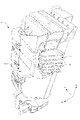
- FIG. 1A is a perspective view showing the internal configuration of the head-up display 1 according to the embodiment from above.
- FIG. 1B is a perspective view showing the head-up display 1 from below.
- FIG. 1C is a perspective view showing the TFT panel unit 3.
- FIG. 1D is a perspective view showing the backlight unit 6 and the heat radiating member 7.
- FIG. 2 is a diagram schematically showing a vehicle-mounted state of the head-up display 1 when viewed from the vehicle side.
- the illustration of a part of the components of the head-up display 1 is omitted.
- FIG. 1A and 1B the illustration of a part of the components of the head-up display 1 is omitted.
- the X direction, the Y direction, and the Z direction which are three directions orthogonal to each other, are defined in the right-handed system.
- the Z direction is the vertical direction
- the positive side is the upper side
- the negative side is the lower side.
- the head-up display 1 is mounted in the instrument panel 9 of the vehicle.
- the head-up display 1 may be mounted in a direction in which the Y direction of FIG. 1A substantially corresponds to the vehicle width direction.
- the head-up display 1 includes a case 2, a TFT (Thin Film Transistor) panel unit 3, a reflector unit 4, a concave mirror 5, a backlight unit 6, and a heat dissipation member 7.
- TFT Thin Film Transistor
- Case 2 forms a housing for the head-up display 1.
- the case 2 is a lower case that forms the lower part of the housing of the head-up display 1.
- the case 2 is combined with an upper case (not shown in FIG. 1A).
- Case 2 is formed of, for example, resin.
- the case 2 may be formed of two or more members.
- the TFT panel unit 3 is fixed to the case 2.
- the TFT panel unit 3 is a display device that uses the light from the backlight unit 6 as a backlight to emit display light according to the display image.
- the TFT panel unit 3 of this embodiment includes a dot matrix type TFT (Thin Film Transistor) panel.
- the display image is arbitrary, and may be, for example, an image showing navigation information, various vehicle information, and the like.
- the reflector unit 4 is fixed to the case 2.
- the reflecting mirror unit 4 includes a plane mirror 41 and a holder 42 for holding the plane mirror 41, and reflects the display light emitted from the TFT panel unit 3 toward the concave mirror 5.
- the concave mirror 5 is fixed to the case 2.
- the concave mirror 5 is rotatably supported with respect to the case 2 so that the vertical position of the area exposed to the display light in the windshield WS can be adjusted.
- the concave mirror 5 reflects the display light reflected by the reflector unit 4 and emits it from an exit port provided in the upper case (not shown) so as to face the windshield WS of the vehicle VC.
- the backlight unit 6 is provided behind the TFT panel unit 3 (negative side in the Y direction).
- the backlight unit 6 includes, for example, a substrate 60 on which an LED 62 (Light Emitting Diode) is mounted.
- the substrate 60 may be placed on the heat radiating member 7 as shown in FIG. 1D.
- the backlight unit 6 cooperates with the TFT panel unit 3 to generate display light.
- the heat radiating member 7 is formed of a highly heat-conducting material such as aluminum.
- the heat radiating member 7 is attached to the case 2 so that the fins 71 are exposed on the outside of the case 2.
- the heat radiating member 7 has a function of radiating heat generated from the backlight unit 6. The heat radiating member 7 releases heat to the air flowing outside the case 2.
- a head-up display 1 As shown in FIG. 2, when the windshield WS is irradiated with the display light, the driver who drives the vehicle VC obtains the windshield WS in front of the windshield WS by the irradiation.
- the displayed image (virtual image display) VI can be seen.
- the driver can visually recognize the displayed image VI by superimposing it on the landscape in front, and can grasp the vehicle information and the like in a mode in which the line of sight movement is small, and the convenience and safety are improved.
- FIG. 3 is a perspective view of the reflector unit 4 in a single item state
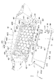
- FIG. 4 is an exploded perspective view of the reflector unit 4.
- FIG. 5 is a perspective view of the holder 42 as a single item as viewed from the front side in the insertion direction (see arrow R1 in FIG. 4).
- FIG. 6 is an explanatory diagram of the shape of the second urging portion 432.
- FIG. 7 is an explanatory view of the opening on the entrance side, and is an enlarged perspective view of the Q1 portion of FIG. 4 from different directions.
- the A direction, the B direction, and the C direction are defined separately from the X direction, the Y direction, and the Z direction described above.
- the A direction is a direction perpendicular to the reflection surface of the plane mirror 41, and the terms "A1 side” and "A2 side” represent relative positional relationships with respect to a certain member, and the A1 side is a plane mirror.
- the side from the center position of 41 in the A direction toward the reflection surface of the plane mirror 41 is relatively represented, and the A2 side is relatively represented from the center position of the plane mirror 41 in the A direction toward the back surface of the plane mirror 41.
- the B direction (an example of the second direction) is one direction orthogonal to the A direction, and corresponds to the insertion direction of the plane mirror 41 into the holder 42 at the time of assembly. Further, the B1 side relatively represents the back side in the insertion direction, and the B2 side relatively represents the front side in the insertion direction.
- the C direction (an example of the first direction) is a direction orthogonal to both the A direction and the B direction, and the C1 side relatively represents the side of the plane mirror 41 from the center position in the C direction toward the side L4, and is C2. The side relatively represents the side of the plane mirror 41 toward the side L3 side from the center position in the C direction.
- the reflector unit 4 includes a plane mirror 41 and a holder 42.
- the plane mirror 41 forms a reflective surface that reflects the display light emitted from the TFT panel unit 3 toward the concave mirror 5.
- the plane mirror 41 has a substantially constant thickness and has a rectangular outer shape.
- the plane mirror 41 has a trapezoidal shape in which the sides L1 and L2 are parallel, the angle formed by the side L1 and the side L4 is 90 degrees, and the angle formed by the side L1 and the side L3 is larger than 90. big. That is, in the plane mirror 41, the angle between the side surface on the side L1 side and the side surface on the side L4 side is 90 degrees, and the angle between the side surface on the side L1 side and the side surface on the side L3 side is larger than 90 degrees.
- the side surface on the side L1 side and the side surface on the side L4 side may have a so-called pin angle or may be connected by a curved surface (R surface). The same applies to the side surface on the side L1 side and the side surface on the side L3 side.
- the holder 42 is formed of, for example, resin.
- the holder 42 holds the plane mirror 41.
- the holder 42 is fixed to the case 2. Therefore, the plane mirror 41 is supported by the case 2 via the holder 42.
- the holder 42 abuts on the plane mirror 41 and is elastically deformed so that the displacement of the plane mirror 41 with respect to the holder 42 in the A direction and the axis of the plane mirror 41 with respect to the holder 42 parallel to the A direction (for example, the centroid). It has a function of restraining the displacement around (the axis parallel to the A direction) passing through.
- the holder 42 includes a base portion 420, a first portion 421, a second portion 422, a third portion 423, a first urging portion 431, a second urging portion 432, and a third. It includes an urging unit 433, a first guide unit 441, a second guide unit 442, and a third guide unit 443.
- the base portion 420 extends in the region where the plane mirror 41 overlaps when viewed in the A direction.
- the base portion 420 has a planar shape.
- the base portion 420 preferably has ribs 4201 arranged in a honeycomb shape on the side facing the plane mirror 41 in the A direction (A1 side), as shown in FIG.
- the rib 4201 is erected on the flat surface portion 4200.
- the rib 4201 may be formed of another pattern (a pattern other than the honeycomb shape) as long as it functions to increase the rigidity.
- the base portion 420 further has a frame portion 4202 whose height (height in the A direction) from the flat surface portion 4200 is slightly larger than that of the rib 4201.
- the frame portion 4202 extends in the vicinity of each of the first urging portion 431, the second urging portion 432, and the third urging portion 433, which will be described later, and has a function of ensuring the required rigidity.
- the base portion 420 has a window portion 4205 penetrating in the A direction within a range in which the plane mirror 41 overlaps when viewed in the A direction.
- the window portion 4205 is provided so that the state in which the plane mirror 41 is inserted into the holder 42 in a desired manner can be confirmed. Therefore, the window portion 4205 is preferably provided on the inner side in the insertion direction. In this case, by confirming that the plane mirror 41 is visible through the window portion 4205, it is possible to confirm that the plane mirror 41 is inserted into the holder 42 in a desired manner.
- three window portions 4205 are provided side by side in the C direction.
- the first portion 421 is separated from the base portion 420 toward the A1 side in the A direction by a distance slightly larger than the thickness of the plane mirror 41. Therefore, the first portion 421 extends in a range overlapping the base portion 420 when viewed in the A direction.
- the first portion 421 is provided so as to face the portions on both sides of the base portion 420 in the C direction and the portions on the B direction B1 side of the base portion 420 so as to face each other in the A direction.
- the first portion 421 abuts in the A direction with respect to the surface of the plane mirror 41 on the reflective surface side at the edge portion of the plane mirror 41 on the three sides (sides L1, side L3, and side L4).
- the first portion 421 has a function of restraining the displacement of the plane mirror 41 in the A direction with respect to the holder 42 in cooperation with the first urging portion 431 described later. That is, the first portion 421 abuts on the surface of the plane mirror 41 on the reflection surface side from the A direction A1 side, thereby restricting the displacement of the plane mirror 41 toward the A direction A1 side.
- such a function of restraining the displacement in the A direction is also referred to as an “A direction displacement restraining function”.
- the first portion 421 extends in a C shape when viewed in the A direction, and therefore extends along the three sides (side L1, side L3, and side L4) of the plane mirror 41. , Can come into contact with the plane mirror 41.
- the first portion 421 may be provided in another embodiment.
- the first portion 421 may be provided so as to face only the portions on both sides of the base portion 420 in the C direction in the A direction.
- the second portion 422 is erected on the A1 side in the A direction at the position (boundary position) on the back side (B1 side in the B direction) of the base portion 420 in the insertion direction.
- the second portion 422 does not extend continuously in the C direction, but is formed in such a manner that the opening 4221 is formed in between.
- the second portion 422 abuts in the B direction with respect to the side surface of the plane mirror 41 on the inner side (that is, the side L1 side) in the insertion direction.
- the second portion 422 has a function of restraining the displacement of the plane mirror 41 in the B direction with respect to the holder 42 in cooperation with the second urging portion 432 described later. That is, the second portion 422 abuts on the side surface of the plane mirror 41 on the B direction B1 side from the B direction B1 side, thereby restricting the displacement of the plane mirror 41 toward the B direction B1 side.
- a function of restraining the displacement in the B direction is also referred to as a “displacement restraining function in the B direction”.
- the second portion 422 has an opening 4221 in between, but is arranged along the C direction in such a manner that the plane mirror 41 faces the entire side surface of the plane mirror 41 on the B direction B1 side. Therefore, the above-mentioned B-direction displacement restraint function can be effectively enhanced.
- the second portion 422 may be provided in another embodiment.
- the third portion 423 is erected on the A1 side in the A direction at the position (boundary position) on the C1 side in the C direction in the base portion 420.
- the third portion 423 is formed in a mode continuous with the first portion 421 on the C1 side in the C direction (a mode in which an L-shaped cross section is formed when viewed in the B direction), and the third portion 423 is formed on the C1 side in the C direction. It extends in the B direction in the same range as one site 421.
- the third portion 423 abuts in the C direction with respect to the side surface of the plane mirror 41 on the C1 side in the C direction.
- the third portion 423 has a function of restraining the displacement of the plane mirror 41 in the C direction with respect to the holder 42 in cooperation with the third urging portion 433 described later. That is, the third urging portion 433 regulates the displacement of the plane mirror 41 toward the C1 side in the C direction by abutting the side surface of the plane mirror 41 on the C1 side in the C direction from the C1 side in the C direction.
- a function of restraining the displacement in the C direction is also referred to as a “displacement restraining function in the C direction”.
- the third portion 423 is arranged along the B direction in such a manner that the third portion 423 faces substantially the entire side surface of the plane mirror 41 on the C1 side in the C direction, so that the above-mentioned C direction displacement restraining function can be effectively performed. Can be enhanced.
- the third portion 423 may be provided in another embodiment.
- the first urging unit 431 is provided within a range overlapping the plane mirror 41 when viewed in the A direction.
- two first urging portions 431 are provided on both sides of the C direction in a range overlapping the plane mirror 41 when viewed in the A direction.
- the first urging portion 431 abuts on the back surface of the plane mirror 41 and elastically deforms mainly toward the A2 side in the A direction to apply a force in the A direction to the plane mirror 41.
- the first urging portion 431 has a claw-shaped shape, and the tip portion is located on the A1 side in the A direction with respect to the base portion 420 in the state before the plane mirror 41 is assembled to the holder 42.
- the tip portion of the first urging portion 431 is displaced toward the A2 side in the A direction, and the first urging portion 431 is elastically deformed.
- the first urging unit 431 can apply a force toward the A1 side in the A direction to the plane mirror 41.
- the displacement of the plane mirror 41 toward the A1 side in the A direction is regulated by the first portion 421.
- the first urging unit 431 cooperates with the first portion 421 to realize the above-mentioned A-direction displacement restraining function.
- the first urging portions 431 are provided at four locations so as to act on both sides of the plane mirror 41 in the C direction and both sides in the B direction.
- the first urging portion 431 may be provided in another embodiment.
- the first urging portion 431 may be additionally provided in the vicinity of the first portion 421 on the B1 side in the B direction.
- the second urging portion 432 is provided on the B2 side in the B direction in a range overlapping the plane mirror 41 when viewed in the A direction.
- three second urging portions 432 are provided side by side in the C direction as shown in FIG.
- the second urging portion 432 abuts on the side portion 418 on the front side (B direction B2 side) of the plane mirror 41 in the insertion direction and elastically deforms to apply a force in the B direction to the plane mirror 41.
- the second urging portion 432 has a claw-shaped shape and has a return portion 4322 that engages with the side portion 418 on the front side in the insertion direction in the plane mirror 41.
- the return portion 4322 has a side portion 418 on the B direction B2 side of the plane mirror 41 (to be exact, the A direction A2 side of the side portion 418) in a state where the second urging portion 432 is elastically deformed mainly toward the A direction A2 side. Contact the corners of).
- the second urging portion 432 can apply a force toward the B1 side in the B direction to the plane mirror 41.
- the displacement of the plane mirror 41 in the B direction to the B1 side is regulated by the second portion 422.
- the second urging unit 432 cooperates with the second portion 422 to realize the above-mentioned B-direction displacement restraining function.
- the second urging portion 432 may be provided in another embodiment.
- the second urging unit 432 one of the three may be omitted.
- the three second urging portions 432 have substantially the same form as each other, but the detailed portions may be different.
- the second urging unit 432 is located on the B direction B2 side with respect to the plane mirror 41 in order to realize the above-mentioned B direction displacement restraining function.
- the second urging portion 432 that can improve the assembling property when the plane mirror 41 is inserted into the holder 42 while enhancing the above-mentioned B-direction displacement restraining function.
- the configuration of is realized.
- the edge portion 4320 on the front side in the insertion direction of the second urging portion 432 is larger than the edge portion 4421 on the front side in the insertion direction in the second guide portion 442.
- the distance from the back surface of the plane mirror 41 in the A direction is large. That is, the edge portion 4320 of the second urging portion 432 is located on the A2 side in the A direction with respect to the edge portion 4421 of the second guide portion 442.
- the second urging portion 432 has a first inclined surface 43221, a first plane 43222, a second plane 4328, and a second inclined surface 4329 on the A1 side in the A direction.
- the first inclined surface 43221 is an inclined direction toward the A direction A2 side as it goes from the edge portion 4320 to the B direction B1 side when viewed in the C direction.
- the first plane 43222 is perpendicular to the back surface of the plane mirror 41.
- the first plane 43222 is continuous with respect to the first inclined surface 43221 from the B2 side in the B direction.
- the first plane 43222 cooperates with the first inclined surface 43221 to form the return portion 4322 described above.
- the side portion 418 on the B direction B2 side of the plane mirror 41 (to be exact, the corner portion on the A direction A2 side of the side portion 418) abuts on the first inclined surface 43221.
- the first plane 43222 is perpendicular to the back surface of the plane mirror 41, the first plane 43222 is a plane mirror even if the plane mirror 41 abutting on the first inclined surface 43221 tries to be displaced toward the B2 side in the B direction. It becomes easy to lock 41. As a result, the above-mentioned B-direction displacement restraining function can be effectively enhanced.
- the second plane 4328 is connected to the first plane 43222 from the B2 side in the B direction.
- the second plane 4328 is parallel to the back surface of the plane mirror 41.
- the second plane 4328 may be connected to the first plane 43222 via a curved surface 43281 having a relatively small radius of curvature.
- the center of curvature of the curved surface 43281 is on the A2 side.
- the second inclined surface 4329 is connected to the second plane 4328 from the B2 side in the B direction.
- the second inclined surface 4329 has an inclined direction opposite to that of the first inclined surface 43221. That is, the second inclined surface 4329 is an inclined direction toward the A1 side as it goes from the edge portion 4320 to the B direction B1 side when viewed in the C direction.
- the slope of the second inclined surface 4329 may be smaller than that of the first inclined surface 43221.
- the second inclined surface 4329 may be connected to the second plane 4328 via a curved surface 44211 having a relatively large radius of curvature.
- the center of curvature of the curved surface 44211 is on the A2 side.
- the third urging portion 433 is provided on the C2 side in the C direction and the B1 side in the B direction with respect to the base portion 420.
- the third urging portion 433 abuts on the side surface of the plane mirror 41 on the C2 side in the C direction and elastically deforms mainly toward the C2 side in the C direction to apply a force in the C direction to the plane mirror 41.
- the third urging portion 433 has a claw-shaped shape, and the tip portion protrudes toward C1 in the C direction.
- the third urging unit 433 can apply a force toward the C1 side in the C direction to the plane mirror 41.
- the displacement of the plane mirror 41 toward the C1 side in the C direction is regulated by the third portion 423.
- the third urging unit 433 cooperates with the third portion 423 to realize the above-mentioned C-direction displacement restraining function.
- only one third urging unit 433 is provided, but two or more may be provided.
- the third urging portion 433 is preferably placed only on the inner side (B1 side in the B direction) of the side surface on the C2 side of the plane mirror 41 in the C direction. Contact.
- the plane mirror 41 when the plane mirror 41 is inserted into the holder 42 at the time of assembly, the plane mirror 41 interferes with the third urging portion 433 near the final stage of insertion (as a result, the third urging portion 433 is elastically deformed). Therefore, the assembling property is improved as compared with the case where the plane mirror 41 interferes with the third urging portion 433 at the start stage of insertion.
- the first guide portion 441 is provided on the B2 side in the B direction with respect to the first portion 421.
- the first guide portion 441 is in a form continuous with respect to the first portion 421 from the B2 side in the B direction.
- the first guide portion 441 positions the side portions of the plane mirror 41 on both sides in the C direction at appropriate positions in the A direction (for example, the surface on the A1 side in the A direction is the first portion 421). It functions to be positioned at the position (position in contact with the surface on the A2 side in the A direction).
- the first guide portion 441 is preferably the height in the A direction (smaller than the thickness of the plane mirror 41) of the space formed between the first portion 421 and the base portion 420 in the A direction. It has a tapered portion 4211 such that the width becomes larger toward the B2 side in the B direction.
- FIG. 7 shows the first guide portion 441 on the C1 side in the C direction, the same applies to the first guide portion 441 on the C2 side in the C direction.
- one or both of the first guide portions 441 on the C1 side and the C2 side in the C direction may be omitted.
- the second guide portion 442 is provided on the B2 side in the B direction with respect to the base portion 420.
- the second guide portion 442 is continuous with respect to the base portion 420 from the B2 side in the B direction.
- the second guide portion 442 positions the back surface of the plane mirror 41 in an appropriate A direction (for example, the B direction B1 side of the back surface of the plane mirror 41 is the second urging portion 432. 2 It functions to be positioned at the position where it rides on the inclined surface 4329).
- the second guide portion 442 preferably has a corner R (see the tapered portion 4422 due to a curved surface) as shown in FIG.
- the third guide portion 443 is provided on the B2 side in the B direction with respect to the third portion 423.
- the third guide portion 443 is continuous with respect to the third portion 423 from the B2 side in the B direction.
- the third guide portion 443 positions the side portion of the plane mirror 41 in the C direction at an appropriate position in the C direction (for example, the side surface of the plane mirror 41 on the C direction C1 side is the third portion. It functions to position the 423 at a position in contact with the surface on the C2 side in the C direction.
- the third guide portion 443 preferably realizes a tapered portion 4432 that inclines toward the C1 side in the C direction as the surface on the C2 side in the C direction toward the B2 side in the B direction.
- FIG. 7 shows the third guide portion 443 on the C1 side in the C direction
- a guide portion such as the third guide portion 443 on the C2 side in the C direction (see the third guide portion 443A in FIG. 6). ) May be formed.
- the first guide portion 441, the second guide portion 442, and the third guide portion 443 cooperate with each other to form an opening on the entrance side when the plane mirror 41 is inserted.
- the tapered portions 4211, 4422, and 4432 are provided so that the opening when viewed in the insertion direction becomes wider toward the B2 side in the B direction.
- a part or all of the first guide portion 441, the second guide portion 442 and the third guide portion 443 may be omitted, and a part or all of the tapered portions 4211, 4422, 4432 may be omitted. May be done.
- the first urging portion 431, the second urging portion 432, and the third urging portion 433 are elastically deformed, so that the plane mirror 41 is inserted into the holder 42. Good assembling property.
- the holder 42 is elastically deformed so that the displacement of the plane mirror 41 with respect to the holder 42 in the three directions (A direction, B direction, and C direction) is substantially free of play. Can be restrained. In this way, according to the present embodiment, it is possible to hold the plane mirror 41 against the holder 42 substantially without play in an aspect in which the assembling property is good.
- the first urging portion 431 abuts on the back surface of the plane mirror 41, but the present invention is not limited to this.
- the first urging portion 431 may abut on the surface of the plane mirror 41 on the reflection surface side and apply a force toward the A2 side in the A direction to the plane mirror 41.
- the first urging portion 431 may be provided, for example, on the side of the first portion 421.
- the back surface of the plane mirror 41 comes into contact with the base portion 420, so that the displacement toward the A2 side in the A direction is constrained.
- the third urging unit 433 is provided on the C2 side in the C direction, but may be provided on the C1 side in the C direction.
- the third portion 423 is provided on the C2 side in the C direction.
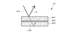
- FIG. 8 is a cross-sectional view showing the plane mirror 41 of the first embodiment.
- FIG. 9 is an explanatory diagram of the operation of the plane mirror 41.
- the planar mirror 41 of the first embodiment includes a reflective layer 411, an adhesive layer 412, and a base material 413 to which the reflective layer 411 is bonded via the adhesive layer 412.
- the reflective layer 411 faces the TFT panel unit 3 and the concave mirror 5.
- the adhesive layer 412 and the base material 413 are arranged behind the reflective layer 411.
- the reflective layer 411 is a reflective polarizing multilayer film.
- the reflective polarizing multilayer film is a film in which polyester resin films having different refractive indexes are laminated in several hundred layers.
- the refractive index of each film is adjusted so that the reflective layer 411 reflects only a specific polarization component of visible light I.
- the reflective layer 411 has wavelength selectivity with respect to the reflected wavelength, and allows infrared light J to pass through without being reflected.
- the reflection layer 411 has a reflection axis and reflects a linearly polarized component of visible light I parallel to the reflection axis direction Rr.
- the reflection axis direction Rr may be parallel to the above-mentioned C direction.
- the reflective layer 411 passes the linearly polarized component of visible light I perpendicular to the reflection axis direction Rr without being reflected.
- the reflection layer 411 When the reflection axis direction Rr of the reflection layer 411 is parallel to the direction orthogonal to the incident plane D (the plane formed by the incident light E and the reflected light F), the reflection layer 411 has a wave component parallel to the incident plane D. It transmits the P-polarized light G (not shown) of a certain visible light I. Further, the reflection layer 411 reflects the S-polarized H of visible light I, which is a wave component orthogonal to the incident plane D.
- the plane mirror 41 provided with such a reflective layer 411, it is possible to transmit the infrared light J among the external light such as sunlight incident from the outside and prevent the light from reaching the TFT panel unit 3. Further, since the reflective layer 411 reflects only the S-polarized light H among the visible light I contained in the external light and transmits the P-polarized light G, a glass plate with a polarizing film or the like is arranged in the vicinity of the TFT panel unit 3. It is possible to reduce the visible light directed to the TFT panel unit 3 without doing so.
- the adhesive layer 412 is made of an acrylic resin and is a colorless and transparent translucent adhesive layer.
- the reflective layer 411 and the adhesive layer 412 are supplied as an integral member, and the total thickness thereof is about 60 ⁇ m.
- the base material 413 is a member that holds the reflective layer 411 well with flatness and flatness, and has vibration resistance and transparency.
- transparent inorganic glass is used. Considering economy and rigidity as the plane mirror 41 of the head-up display 1, inorganic glass having a thickness of 1.7 to 2.1 mm is applied.
- the plane mirror 41 is arranged in a direction in which the reflection axis direction Rr of the reflection layer 411 is substantially parallel to the polarization direction of the display light emitted from the TFT panel unit 3.
- the head-up display 1 of the present embodiment shown in FIG. 1A is a so-called horizontal folding type in which the plane mirror 41 reflects the display light from the TFT panel unit 3 in the horizontal direction (direction closer to the horizontal direction than the vertical direction). be. Therefore, in the plane mirror 41, the incident plane D regarding the display light from the TFT panel unit 3 is closer to the horizontal plane than the vertical plane, and the reflection axis direction Rr of the reflection layer 411 is substantially parallel to the direction orthogonal to the incident plane D. It is arranged in the direction of. Specifically, the plane mirror 41 is arranged in a direction in which the reflection axis direction Rr of the reflection layer 411 is in the vertical direction (direction closer to the vertical direction than the horizontal direction).
- the incident angle of the display light from the TFT panel unit 3 to the plane mirror 41 is 30 ° to 40 °.
- the concave mirror 5 and the TFT panel unit 3 can be arranged at close positions, so that the head-up display 1 can be miniaturized.
- FIG. 10 is a cross-sectional view showing the plane mirror 41B of the second embodiment.
- FIG. 11 is a cross-sectional view showing the plane mirror 41C of the third embodiment.
- FIG. 12 is a cross-sectional view showing the plane mirror 41D of the fourth embodiment.
- the P-polarized G of the infrared light J and the visible light I contained in the external light such as sunlight is prevented from heading toward the TFT panel unit 3, it is shielded from the external light. Increased heat.
- a part of the light (infrared light J or P-polarized G) transmitted through the reflective layer 411 is reflected on the back surface of the base material 413, and the reflective layer. It may pass through 411 again and head toward the TFT panel unit 3.
- the temperature rise of the TFT panel unit 3 due to such retransmitted light may reach about 10 ° C. at 1,000 W / m 2 of sunlight.
- the modeling of the holding member may be reflected in the display image.
- the base material 413B has a light-shielding property.
- the light-shielding base material 413B is not colorless and transparent but is colored, and is composed of, for example, a black resin plate. According to such a plane mirror 41B, since the light transmitted through the reflection layer 411 is absorbed by the base material 413B, the heat shielding effect of the plane mirror 41B can be enhanced. Further, according to the base material 413B having a light-shielding property, it is possible to prevent the modeling of the holding member of the plane mirror 41B from being reflected in the display image.
- the adhesive layer 412C has a light-shielding property.
- the light-shielding adhesive layer 412C is not colorless and transparent but is colored, and is composed of, for example, a black adhesive. According to such a plane mirror 41C, the same effect as that of the plane mirror 41B of the second embodiment can be obtained.
- the plane mirror 41D of the fourth embodiment is provided with a light-shielding layer 414 having a light-shielding property on the back surface of the base material 413 (the surface opposite to the reflection layer 411).
- the light-shielding layer 414 is composed of a print layer printed with colored ink, which is not colorless and transparent, a colored adhesive film, and the like. According to such a plane mirror 41D, the same effect as that of the plane mirror 41B of the second embodiment can be obtained.
- the light-shielding layer 414 is composed of a print layer, it is preferably composed of a black oil-based ink or a UV curable ink having a refractive index close to that of the base material 413.
- the light-shielding layer 414 is made of an adhesive film, it is preferably made of a black adhesive film that is attached via an adhesive having a refractive index close to that of the base material 413. With such a configuration, the reflectance at the interface between the base material 413 and the light-shielding layer 414 is lowered, so that the light transmitted through the reflection layer 411 can be reliably absorbed by the light-shielding layer 414.
- the plane mirror 41D of the fourth embodiment when used, the same applies to the cases of the first to third embodiments, but the mode in which the plane mirror 41D deviates from the desired direction with respect to the holder 42 in the reflection axis direction Rr. Then, if it rattles, the quality of the display image generated by the head-up display 1 tends to deteriorate.
- the holder 42 can hold the plane mirror 41D without rattling as described above, the possibility of such deterioration of quality can be effectively reduced.
- the light-shielding layer 414 may be pressed by the above-mentioned first urging portion 431 and the second urging portion 432, resulting in peeling or the like.
- the light-shielding layer 414 is preferably formed with a thickness that does not cause such peeling.
- the light-shielding layer 414 when the light-shielding layer 414 is formed by a print layer printed with colored ink, it may be realized by superimposing the print layers produced by printing two or more times. As a result, even if the light-shielding layer 414 is pressed against the first urging portion 431 or the second urging portion 432 described above, the possibility that the light-shielding layer 414 is peeled off can be reduced.
- the reflective layer 411 is a corner portion thereof (a corner portion of the side L1 and the side L3 in FIG. 4, a corner portion of the side L1 and the side L4, a corner portion of the side L2 and the side L3, and a corner portion of the side L2 and the side L4, respectively. There is a risk of peeling from the corners corresponding to.
- the reflective layer 411 preferably corresponds to each of the corners of the sides L1 and L3, the corners of the sides L1 and L4, the corners of the sides L2 and L3, and the corners of the sides L2 and L4.
- a corner R is imparted to the corner portion to be used.
- FIG. 13 shows, as an example, the angle R (see arrow 1300) of the reflective layer 411 at one corner.
- the outer peripheral edge of the reflective layer 411 has a clearance ⁇ 1 of about 0.1 to 0.5 mm from the end surface of the C surface portion of the base material 413.
- the clearance ⁇ 1 may be set larger so that contact (contact) between the holder 42 and the reflective layer 411 does not occur, as will be described later.
- FIG. 14 is an explanatory diagram schematically showing how the resin film forming the reflective layer 411 is rolled.
- FIG. 15 is a plan view showing the relationship between the reflective layer 411 and the base material 413.
- FIG. 16 is a perspective view showing the relationship between the reflective layer 411 and the base material 413. In FIG. 16, for convenience, the reflective layer 411 is shown by a dotted line.
- the reflective polarizing multilayer film which is a resin film forming the reflective layer 411, is formed by rolling the material 1400 at the nip between the rotating rolls 1450 (see arrow R140) (see arrow R140). See arrow R142).
- the material to be rolled may be a material after multi-layering or a material before multi-layering.
- Such a resin film tends to cause the following inconveniences in a high temperature environment.
- the reflective characteristics of the reflective layer 411 may be distorted and the intended reflective characteristics may not be obtained.
- the reflected light at the stressed part tends to appear rainbow-colored instead of white.
- the cracked portion may lose its function as a reflecting mirror.
- the linear expansion coefficient of the resin reflective layer 411 is larger than that of the inorganic glass base material 413 (the reflective layer 411 expands more at high temperature), the above-mentioned inconvenience is caused in a high temperature environment. It is easy to occur.
- the stress that can occur in the reflective layer 411 can also be generated by interference (contact, etc.) with another object such as the holder 42 with the reflective layer 411, in addition to the thermal stress described above.
- the reflective layer 411 may be damaged and the reflective layer 411 may be cracked.
- the holder 42 preferably abuts on the portion of the base material 413 where the reflective layer 411 is not provided.
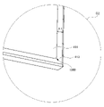
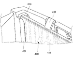
- the reflective layer 411 has three sides of the plane mirror 41D among the edges 4131, 4132, 4133, and 4134 related to the four sides of the base material 413 (as shown in FIG. It is provided inside the edges 4131, 4133, and 4134 related to the sides L1, the side L3, and the side L4). That is, the reflective layer 411 is provided on the base material 413 so as not to extend to the edges of the plane mirror 41D having three sides (sides L1, side L3, and sides L4).
- the first portion 421 of the holder 42 is the reflection surface side of the plane mirror 41D at the edges 4131, 4133, and 4134 related to the three sides (sides L1, side L3, and side L4) of the plane mirror 41D. It abuts in the A direction with respect to the surface of.
- FIG. 16 shows the relationship between the first portion 421 and the reflective layer 411 in a perspective view. This makes it possible to reduce the possibility of cracks or the like occurring in the reflective layer 411 due to the first portion 421.
- the plane mirror 41D is inserted into the holder 42 in such a direction that the rolling direction of the resin film related to the reflective layer 411 intersects the insertion direction (B direction) of the plane mirror 41D with respect to the holder 42 at the time of assembly. Will be done.
- the reflective layer 411 is formed on the base material 413 so that the rolling direction corresponds to the C direction.
- the cracks generated in the reflective layer 411 tend to tear in the direction along the rolling direction of the reflective layer 411 (the C direction shown in FIG. 4, see the arrow R15 in FIG. 15). Therefore, if a crack occurs on either one of both ends of the reflective layer 411 in the rolling direction, the crack may propagate to the other side along the rolling direction.
- the first portion 421 that abuts on the three sides (side L1, side L3, and side L4) of the plane mirror 41D is It extends in a direction orthogonal to the rolling direction of the resin film related to the reflective layer 411. Therefore, by configuring the first portion 421 so as not to come into contact with the reflection layer 411, it is possible to effectively reduce the possibility of unwanted cracks or the like occurring in the reflection layer 411 due to the first portion 421.
- the reflective layer 411 does not abut on the first portion 421 that abuts on the three sides (sides L1, side L3, and side L4) of the plane mirror 41D, so that the reflection layer 411 does not abut on the three sides (sides) of the plane mirror 41D. It is formed inside, but is not limited to, the edges 4131, 4133, and 4134 related to L1, side L3, and side L4). For example, although the reflective layer 411 is formed inside the edge portions 4133 and 4134 (an example of the first edge portion) related to the two sides (sides L3 and L4) of the plane mirror 41D, the edge portion 4131 related to the side L1 is formed.
- the second edge portion may be formed so as to extend from the edge portion 4131 to the outside (for example, the end surface of the C-plane portion of the base material 413 or its vicinity).
- the reflective layer 411 is formed so that the edge portion 4132 (an example of the second edge portion) related to the other side L2 extends to the end surface of the C-plane portion of the base material 413 or its vicinity.
- it may be formed inside the edge portion 4132 related to the side L2 as in the case of the edge portions 4131, 4133, and 4134 related to the three sides (side L1, side L3, and side L4).
- the resin film related to the reflective layer 411 has a predetermined shape (in this example, the sides L1 and L2 are parallel to each other) by using a punching mold having a cutting blade after rolling the material 1400. It is formed by punching into a trapezoidal form).
- the punching mold may be a Thomson type or the like in which a step is generated at the joint of the blades, or a Pinnacle (registered trademark) type or the like in which a step is not generated.
- FIG. 17 is an explanatory view of an example of a die for punching, and is a plan view showing an example of a die 1700 that can be used when punching the reflective layer 411.
- FIG. 18 is a cross-sectional view taken along the line DD of FIG.
- FIG. 19 is a schematic enlarged view of the Q3 part of FIG.
- the mold 1700 shown in FIGS. 17 and 18 is a Thomson type and has a joint 1704 of a cutting blade 1702 as shown in FIG. That is, the cutting blade 1702 has both end portions 17021 butted so as to extend along the outer shape of a predetermined shape (in this example, a trapezoidal form in which the sides L1 and L2 are parallel) according to the outer shape of the reflective layer 411. ..
- a joint 1704 between both end portions 17021 may cause a fine notch due to the joint on the end surface (cut surface) of the cut resin film. When a fine notch is generated, cracks are likely to occur due to the concentration of force on the notch.
- the resin film forming the reflective layer 411 is preferably cut at a straight line portion where the side L1 or the side L2 is located at the joint (that is, both ends of the joint) in the cutting blade 1702.
- the possibility of cracks or the like occurring in the resin film can be reduced as compared with the case where the side L3 or the side L4 is cut at the straight line portion where the joint is located in the cutting blade 1702.
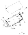
- FIG. 20 is a perspective view showing another example reflector unit 4B.
- FIG. 21 is an exploded perspective view showing another example reflector unit 4B.
- FIG. 22 is a perspective view of a main part showing the reflector unit 4B of another example.
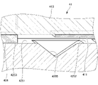
- FIG. 23 is a cross-sectional view of a main part showing the reflector unit 4B of another example.
- the reflector unit 4B of another example is different from the above-described embodiment in that the plane mirror 41 is fixed to the holder 42B by the adhesive 424.
- the adhesive 424 is liquid at least at the time of application, and for example, a hot melt adhesive is used.
- the holder 42B of another example includes a first surface 425 to which the plane mirror 41 is adhered, and a second surface 427 that exposes the reflective layer 411 of the plane mirror 41 through the opening 426. To prepare for.
- the first surface 425 of the holder 42B has a first facing portion 4251 facing a portion of the base material 413 of the plane mirror 41 not provided with the reflection layer 411, and a reflection layer of the plane mirror 41.
- the adhesive portion 4253 is provided on the first facing portion 4251, and the portion of the base material 413 of the plane mirror 41 where the reflective layer 411 is not provided is fixed via the adhesive 424.
- the adhesive portions 4253 are provided at three points on the first surface 425 along the edge portion of the opening 426, and the three sides of the plane mirror 41 are the adhesive portions via the adhesive 424. It is fixed to 4253.
- the contact portion 4254 projects from the first facing portion 4251 and abuts on the portion of the base material 413 of the plane mirror 41 where the reflection layer 411 is not provided, so that the contact portion 4254 and the base material 413 of the plane mirror 41 and the adhesive portion 4253 come into contact with each other. It defines the distance from and, that is, the thickness of the adhesive 424.
- a contact portion 4254 having a quadrangular plane as a contact surface is projected from the four corners of the first surface 425.
- the contact area 4254 shown in FIG. 21 has a relatively small contact area and contact length with the plane mirror 41, but if the thickness of the adhesive 424 can be specified, the number of contact portions 4254, the contact area, and the like. The contact length can be changed as appropriate.
- the groove 4255 is provided between the adhesive portion 4253 and the opening portion 426 so as to be parallel to the adhesive portion 4253.
- the length of the groove 4255 is substantially the same as that of the adhesive portion 4253, or longer than that of the adhesive portion 4253. According to such a groove 4255, in the bonding process of the plane mirror 41, the excess adhesive pressed between the bonding portion 4253 and the plane mirror 41 and flowing to the opening 426 side is accommodated, so that the reflection area of the plane mirror 41 It is possible to prevent excess adhesive from flowing out into a certain opening 426.
- the cross-sectional shape of the groove 4255 is a V-groove shape.
- the cross-sectional shape of the groove 4255 is a square groove shape, the surface tension makes it difficult for excess adhesive to flow into the groove 4255, whereas the V-groove shape groove 4255 suppresses the surface tension and causes excess adhesion. The inflow of the agent can be promoted.
- the reflective layer 411 of the plane mirror 41 causes a crack when it comes into contact with the second facing portion 4252, it is held in a state of being floated by a predetermined dimension from the second facing portion 4252. However, its dimensions are small and excess adhesive can adhere and cause cracks.
- the groove 4255 is located between the adhesive portion 4253 and the second facing portion 4252, and accommodates the excess adhesive in front of the reflective layer 411 to prevent adhesion to the reflective layer 411. can do.
- the groove 4255 is provided between the adhesive portion 4253 and the second facing portion 4252 so as not to overlap with the reflective layer 411.
- the groove 4255 is a reflective layer.
- the groove 4255 is provided so that the center position of the groove width is closer to the adhesive portion 4253 than the end surface of the reflective layer 411. By doing so, it is possible to increase the distance between the end surface of the reflective layer 411 and the groove bottom of the groove 4255, and prevent the excess adhesive from adhering to the reflective layer 411.
Landscapes
- Physics & Mathematics (AREA)
- Engineering & Computer Science (AREA)
- General Physics & Mathematics (AREA)
- Optics & Photonics (AREA)
- Chemical & Material Sciences (AREA)
- Combustion & Propulsion (AREA)
- Transportation (AREA)
- Mechanical Engineering (AREA)
- Rear-View Mirror Devices That Are Mounted On The Exterior Of The Vehicle (AREA)
- Instrument Panels (AREA)
Abstract
Description
表示光を出射する表示装置(3+6)と、
前記表示光を反射する平面鏡(41)と、
前記平面鏡を保持するホルダ(42)と、を備え、
前記平面鏡は、基材と、前記基材に設けられかつ樹脂フィルムを含む反射層とを有し、
前記ホルダは、前記基材における前記反射層が設けられない部分に当接する、ヘッドアップディスプレイ(1)が開示される。
図1Aは、一実施例によるヘッドアップディスプレイ1の内部構成を上側から示す斜視図である。図1Bは、ヘッドアップディスプレイ1を下側から示す斜視図である。図1Cは、TFTパネルユニット3を示す斜視図である。図1Dは、バックライトユニット6及び放熱部材7を示す斜視図である。図2は、ヘッドアップディスプレイ1の車両搭載状態を車両側方視で概略的に示す図である。なお、図1A及び図1Bでは、ヘッドアップディスプレイ1の一部の構成要素の図示は省略されている。図1A等には、右手系で、互いに直交する3方向であるX方向、Y方向、及びZ方向が定義されている。以下では、形式上、Z方向を上下方向とし、正側を上側とし、負側を下側とする。
図3は、反射鏡ユニット4の単品状態の斜視図であり、図4は、反射鏡ユニット4の分解斜視図である。図5は、挿入方向(図4の矢印R1参照)の手前側から視たホルダ42の単品状態の斜視図である。図6は、第2付勢部432の形状の説明図である。図7は、入口側の開口の説明図であり、図4のQ1部を拡大した異なる方向からの斜視図である。
つぎに、平面鏡41の好ましい構成について、図8及び図9を参照して説明する。
平面鏡41は、反射層411の反射軸方向RrがTFTパネルユニット3から出射される表示光の偏光方向と略平行となる向きで配置される。このように平面鏡41を配置すると、TFTパネルユニット3に向かう可視光Iを削減しつつ、TFTパネルユニット3からの表示光の減衰を抑えて運転者の視点方向へ反射することができる。
つぎに、第2~第4実施例の平面鏡41B、41C、41Dについて、図10~図12を参照して説明する。ただし、第1実施例と共通の構成については、第1実施例と同じ符号を用いることにより、第1実施例の説明を援用する。
つぎに、上述した実施例4による平面鏡41Dの反射層411に関して、ホルダ42との関係に関する好ましい実施例ついて、図14以降を参照して説明する。以下の実施例は、上述した実施例4による平面鏡41Dに関して説明するが、上述した第1実施例から第3実施例による平面鏡41、41B、41Cについても同様に適用可能である。
つぎに、他例の反射鏡ユニット4Bについて、図20~図23を参照して説明する。ただし、前述の実施例と共通の構成については、前述の実施例と同じ符号を用いることにより、前述の実施例の説明を援用する。
2 ケース
3 TFTパネルユニット
4 反射鏡ユニット
5 凹面鏡
6 バックライトユニット
7 放熱部材
71 フィン
9 インストルメントパネル
41 平面鏡
41B 平面鏡
41C 平面鏡
41D 平面鏡
42 ホルダ
411 反射層
412 粘着層
412C 粘着層
413 基材
413B 基材
414 遮光層
418 側部
420 ベース部
421 第1部位
422 第2部位
423 第3部位
431 第1付勢部
432 第2付勢部
433 第3付勢部
441 第1案内部
442 第2案内部
443 第3案内部
443A 第3案内部
4200 平面部
4201 リブ
4202 枠部
4205 窓部
4211 テーパ部
4221 開口部
4320 縁部
4322 返し部
4328 第2平面
4329 第2傾斜面
4421 縁部
4422 テーパ部
4432 テーパ部
43221 第1傾斜面
43222 第1平面
43281 曲面
44211 曲面
4B 反射鏡ユニット
42B ホルダ
424 接着剤
425 第1面
4251 第1対向部
4252 第2対向部
4253 接着部
4254 当接部
4255 溝
426 開口部
427 第2面
Claims (8)
- 筐体(2)と、
表示光を出射する表示装置(3+6)と、
前記表示光を反射する平面鏡(41)と、
前記平面鏡を保持するホルダ(42)と、を備え、
前記平面鏡は、基材と、前記基材に設けられかつ樹脂フィルムを含む反射層とを有し、
前記ホルダは、前記基材における前記反射層が設けられない部分に当接する、ヘッドアップディスプレイ(1)。 - 前記基材は、前記樹脂フィルムの圧延方向に沿った第1方向(C)の両側に第1縁部と、前記第1方向に交差する第2方向(B)の両側に第2縁部とを含み、
前記反射層は、前記基材における前記第1縁部よりも内側に設けられ、
前記ホルダは、前記第1縁部に当接する、請求項1に記載のヘッドアップディスプレイ(1)。 - 圧延により形成された樹脂フィルム材料を、所定形状の外形に沿って延在するように両端部を突き合わせてなる切断刃により、前記所定形状に切断してなる樹脂フィルムを準備し、
前記樹脂フィルムを含む反射層を基材に設け、
前記反射層が設けられた前記基材を含む平面鏡を、ヘッドアップディスプレイのホルダに挿入して保持させることを含み、
前記切断刃は、前記所定形状のうちの、前記樹脂フィルムの圧延方向に沿った辺に、前記両端部を有する、ヘッドアップディスプレイ(1)の製造方法。 - 前記平面鏡は、前記樹脂フィルムの圧延方向に交差する挿入方向で前記ホルダに挿入される、請求項3に記載のヘッドアップディスプレイ(1)の製造方法。
- 前記ホルダは、前記基材における前記反射層が設けられない部分が、接着剤(424)を介して固定される接着部(4253)を備える、請求項1又は2に記載のヘッドアップディスプレイ(1)。
- 前記ホルダは、
前記反射層と対向する対向部(4252)と、
前記接着部と前記対向部との間に形成される溝(4255)と、を備える、請求項5に記載のヘッドアップディスプレイ(1)。 - 前記ホルダは、
前記反射層を露出させる開口部(426)と、
前記接着部と前記開口部との間に形成される溝(4255)と、を備える請求項5又は6に記載のヘッドアップディスプレイ(1)。 - 前記ホルダは、前記基材における前記反射層が設けられない部分と当接する当接部(4254)を備え、
前記当接部は、前記接着部に塗布される前記接着剤の厚みを規定する、請求項5から7のいずれか1項に記載のヘッドアップディスプレイ(1)。
Priority Applications (4)
| Application Number | Priority Date | Filing Date | Title |
|---|---|---|---|
| JP2022560783A JP7722387B2 (ja) | 2020-11-04 | 2021-11-02 | ヘッドアップディスプレイ及びヘッドアップディスプレイの製造方法 |
| CN202190000834.6U CN219978627U (zh) | 2020-11-04 | 2021-11-02 | 平视显示器 |
| DE112021005783.9T DE112021005783T5 (de) | 2020-11-04 | 2021-11-02 | Head-up-Display und Herstellungsverfahren für ein Head-up-Display |
| US18/248,465 US20230408792A1 (en) | 2020-11-04 | 2021-11-02 | Head-up display and manufacturing method for head-up display |
Applications Claiming Priority (4)
| Application Number | Priority Date | Filing Date | Title |
|---|---|---|---|
| JP2020184487 | 2020-11-04 | ||
| JP2020-184487 | 2020-11-04 | ||
| JP2021-038451 | 2021-03-10 | ||
| JP2021038451 | 2021-03-10 |
Publications (1)
| Publication Number | Publication Date |
|---|---|
| WO2022097638A1 true WO2022097638A1 (ja) | 2022-05-12 |
Family
ID=81457205
Family Applications (1)
| Application Number | Title | Priority Date | Filing Date |
|---|---|---|---|
| PCT/JP2021/040388 Ceased WO2022097638A1 (ja) | 2020-11-04 | 2021-11-02 | ヘッドアップディスプレイ及びヘッドアップディスプレイの製造方法 |
Country Status (4)
| Country | Link |
|---|---|
| US (1) | US20230408792A1 (ja) |
| JP (1) | JP7722387B2 (ja) |
| DE (1) | DE112021005783T5 (ja) |
| WO (1) | WO2022097638A1 (ja) |
Cited By (2)
| Publication number | Priority date | Publication date | Assignee | Title |
|---|---|---|---|---|
| CN114815264A (zh) * | 2022-05-26 | 2022-07-29 | 业成科技(成都)有限公司 | 图像生成单元、其装配方法、抬头显示系统及交通工具 |
| JP2024163736A (ja) * | 2023-05-12 | 2024-11-22 | 矢崎総業株式会社 | 車両用表示装置 |
Citations (4)
| Publication number | Priority date | Publication date | Assignee | Title |
|---|---|---|---|---|
| JP2009258575A (ja) * | 2007-06-05 | 2009-11-05 | Asahi Kasei Corp | 反射シート |
| JP2012056334A (ja) * | 2010-09-03 | 2012-03-22 | Yazaki Corp | ヘッドアップディスプレイ |
| JP2017068190A (ja) * | 2015-10-02 | 2017-04-06 | 日本精機株式会社 | ヘッドアップディスプレイ装置 |
| US20170276866A1 (en) * | 2016-03-28 | 2017-09-28 | Au Optronics Corporation | Display device and backlight module used therein |
Family Cites Families (3)
| Publication number | Priority date | Publication date | Assignee | Title |
|---|---|---|---|---|
| US20040219338A1 (en) * | 2003-05-01 | 2004-11-04 | Hebrink Timothy J. | Materials, configurations, and methods for reducing warpage in optical films |
| JP2013174855A (ja) | 2012-01-24 | 2013-09-05 | Nippon Seiki Co Ltd | ヘッドアップディスプレイ装置 |
| JP6969424B2 (ja) * | 2018-02-20 | 2021-11-24 | 日本精機株式会社 | 平面鏡ユニット |
-
2021
- 2021-11-02 US US18/248,465 patent/US20230408792A1/en active Pending
- 2021-11-02 WO PCT/JP2021/040388 patent/WO2022097638A1/ja not_active Ceased
- 2021-11-02 DE DE112021005783.9T patent/DE112021005783T5/de active Pending
- 2021-11-02 JP JP2022560783A patent/JP7722387B2/ja active Active
Patent Citations (4)
| Publication number | Priority date | Publication date | Assignee | Title |
|---|---|---|---|---|
| JP2009258575A (ja) * | 2007-06-05 | 2009-11-05 | Asahi Kasei Corp | 反射シート |
| JP2012056334A (ja) * | 2010-09-03 | 2012-03-22 | Yazaki Corp | ヘッドアップディスプレイ |
| JP2017068190A (ja) * | 2015-10-02 | 2017-04-06 | 日本精機株式会社 | ヘッドアップディスプレイ装置 |
| US20170276866A1 (en) * | 2016-03-28 | 2017-09-28 | Au Optronics Corporation | Display device and backlight module used therein |
Cited By (4)
| Publication number | Priority date | Publication date | Assignee | Title |
|---|---|---|---|---|
| CN114815264A (zh) * | 2022-05-26 | 2022-07-29 | 业成科技(成都)有限公司 | 图像生成单元、其装配方法、抬头显示系统及交通工具 |
| CN114815264B (zh) * | 2022-05-26 | 2023-11-07 | 业成科技(成都)有限公司 | 图像生成单元、其装配方法、抬头显示系统及交通工具 |
| JP2024163736A (ja) * | 2023-05-12 | 2024-11-22 | 矢崎総業株式会社 | 車両用表示装置 |
| US12596253B2 (en) | 2023-05-12 | 2026-04-07 | Yazaki Corporation | Vehicular display device |
Also Published As
| Publication number | Publication date |
|---|---|
| JP7722387B2 (ja) | 2025-08-13 |
| DE112021005783T5 (de) | 2024-02-15 |
| JPWO2022097638A1 (ja) | 2022-05-12 |
| US20230408792A1 (en) | 2023-12-21 |
Similar Documents
| Publication | Publication Date | Title |
|---|---|---|
| US10001652B2 (en) | Virtual image display apparatus | |
| CN113858730A (zh) | 夹层玻璃及抬头显示系统 | |
| JP7722387B2 (ja) | ヘッドアップディスプレイ及びヘッドアップディスプレイの製造方法 | |
| JP7752761B2 (ja) | 合わせガラス及びヘッドアップディスプレイシステム | |
| JP2020144318A (ja) | 表示モジュールおよび表示装置 | |
| JP2017203898A (ja) | ミラーユニット | |
| RS67555B1 (sr) | Uređaj za prikaz i transportno sredstvo | |
| WO2017208961A1 (ja) | ヘッドアップディスプレイ装置 | |
| CN113878953A (zh) | 夹层玻璃及抬头显示系统 | |
| CN113448102A (zh) | 平视显示器 | |
| WO2022210362A1 (ja) | 画像投影装置 | |
| JP7785067B2 (ja) | ヘッドアップディスプレイシステム | |
| JP6733470B2 (ja) | ヘッドアップディスプレイ装置のミラーユニット | |
| WO2024111398A1 (ja) | 画像投影装置 | |
| JP7476892B2 (ja) | ヘッドアップディスプレイ | |
| JP6969424B2 (ja) | 平面鏡ユニット | |
| US6943956B2 (en) | Combiner and on-vehicle display unit including the same | |
| CN219978627U (zh) | 平视显示器 | |
| JP6787010B2 (ja) | ヘッドアップディスプレイ装置のミラーユニット | |
| WO2021149792A1 (ja) | ヘッドアップディスプレイ | |
| JP7253717B2 (ja) | 投影装置及びヘッドアップディスプレイ | |
| JP7474028B2 (ja) | ヘッドアップディスプレイ | |
| JP2008185753A (ja) | 表示装置 | |
| JPWO2020129777A1 (ja) | 凹面鏡支持装置及び表示装置 | |
| JP2009109798A (ja) | ヘッドアップディスプレイ装置 |
Legal Events
| Date | Code | Title | Description |
|---|---|---|---|
| 121 | Ep: the epo has been informed by wipo that ep was designated in this application |
Ref document number: 21889191 Country of ref document: EP Kind code of ref document: A1 |
|
| ENP | Entry into the national phase |
Ref document number: 2022560783 Country of ref document: JP Kind code of ref document: A |
|
| WWE | Wipo information: entry into national phase |
Ref document number: 202190000834.6 Country of ref document: CN |
|
| WWE | Wipo information: entry into national phase |
Ref document number: 112021005783 Country of ref document: DE |
|
| 122 | Ep: pct application non-entry in european phase |
Ref document number: 21889191 Country of ref document: EP Kind code of ref document: A1 |