WO2022097401A1 - 光学系、光学機器、および光学系の製造方法 - Google Patents
光学系、光学機器、および光学系の製造方法 Download PDFInfo
- Publication number
- WO2022097401A1 WO2022097401A1 PCT/JP2021/036577 JP2021036577W WO2022097401A1 WO 2022097401 A1 WO2022097401 A1 WO 2022097401A1 JP 2021036577 W JP2021036577 W JP 2021036577W WO 2022097401 A1 WO2022097401 A1 WO 2022097401A1
- Authority
- WO
- WIPO (PCT)
- Prior art keywords
- lens group
- lens
- optical system
- negative
- conditional expression
- Prior art date
Links
Images


Classifications
-
- G—PHYSICS
- G02—OPTICS
- G02B—OPTICAL ELEMENTS, SYSTEMS OR APPARATUS
- G02B9/00—Optical objectives characterised both by the number of the components and their arrangements according to their sign, i.e. + or -
- G02B9/34—Optical objectives characterised both by the number of the components and their arrangements according to their sign, i.e. + or - having four components only
-
- G—PHYSICS
- G02—OPTICS
- G02B—OPTICAL ELEMENTS, SYSTEMS OR APPARATUS
- G02B13/00—Optical objectives specially designed for the purposes specified below
-
- G—PHYSICS
- G02—OPTICS
- G02B—OPTICAL ELEMENTS, SYSTEMS OR APPARATUS
- G02B13/00—Optical objectives specially designed for the purposes specified below
- G02B13/18—Optical objectives specially designed for the purposes specified below with lenses having one or more non-spherical faces, e.g. for reducing geometrical aberration
Definitions
- the present invention relates to an optical system, an optical device, and a method for manufacturing the optical system.
- the first optical system includes a first lens group having a positive refractive power, a second lens group having a negative refractive power, and a positive refraction, which are arranged in order from the object side along the optical axis. It has a third lens group having a force and a fourth lens group having a negative refractive power, and at the time of focusing, the second lens group and the third lens group move along the optical axis.
- the distance between adjacent lens groups changes, and the following conditional expression is satisfied. 0.20 ⁇ DG4 / TL ⁇ 0.40
- DG4 the length on the optical axis of the fourth lens group TL: the total length of the optical system in the infinity in-focus state.
- the second optical system includes a first lens group having a positive refractive power, a second lens group having a negative refractive power, and a positive refraction, which are arranged in order from the object side along the optical axis. It has a third lens group having a force and a fourth lens group having a negative refractive power, and at the time of focusing, the second lens group and the third lens group move along the optical axis.
- the distance between adjacent lens groups changes, and the following conditional expression is satisfied.
- LnR1 radius of curvature of the lens surface on the object side in the negative lens arranged on the most image side of the optical system
- LnR2 radius of curvature of the lens surface on the image side in the negative lens arranged on the most image side of the optical system.
- the third optical system includes a first lens group having a positive refractive power, a second lens group having a negative refractive power, and a positive refraction, which are arranged in order from the object side along the optical axis. It has a third lens group having a force and a fourth lens group having a negative refractive power, and at the time of focusing, the second lens group and the third lens group move along the optical axis.
- the distance between adjacent lens groups changes, and the following conditional expression is satisfied. 0.75 ⁇ f1 / (-f2) ⁇ 1.30
- f1 the focal length of the first lens group
- f2 the focal length of the second lens group.
- the fourth optical system includes a first lens group having a positive refractive force, a second lens group having a negative refractive force, and a positive refraction, which are arranged in order from the object side along the optical axis. It has a third lens group having a force and a fourth lens group having a negative refractive force, and at the time of focusing, the second lens group and the third lens group move along the optical axis. The distance between adjacent lens groups changes, and the first lens group has a negative lens that satisfies the following conditional expression.
- ndM1 the refractive index of the negative lens of the first lens group with respect to the d line
- ⁇ dM1 the abbe number of the negative lens of the first lens group
- ⁇ gFM1 the partial dispersion ratio of the negative lens of the first lens group.
- the refractive index of the negative lens of the first lens group with respect to the g line is ngM1
- the refractive index of the negative lens of the first lens group with respect to the F line is nFM1
- C of the negative lens of the first lens group is the refractive index for a line.
- ⁇ gFM1 (ngM1-nFM1) / (nFM1-nCM1) defined by the following equation.
- the optical device according to the present invention is configured to include the above optical system.
- the first method for manufacturing an optical system according to the present invention includes a first lens group having a positive refractive force and a second lens group having a negative refractive force arranged in order from the object side along the optical axis. It is a method of manufacturing an optical system having a third lens group having a positive refractive force and a fourth lens group having a negative refractive force, and is a method for manufacturing the second lens group and the third lens group at the time of focusing. And move along the optical axis, the distance between adjacent lens groups changes, and each lens is arranged in the lens barrel so as to satisfy the following conditional expression. 0.20 ⁇ DG4 / TL ⁇ 0.40 However, DG4: the length on the optical axis of the fourth lens group TL: the total length of the optical system in the infinity in-focus state.
- the second method for manufacturing an optical system according to the present invention includes a first lens group having a positive refractive force and a second lens group having a negative refractive force arranged in order from the object side along the optical axis. It is a method of manufacturing an optical system having a third lens group having a positive refractive force and a fourth lens group having a negative refractive force, and is a method for manufacturing the second lens group and the third lens group at the time of focusing. And move along the optical axis, the distance between adjacent lens groups changes, and each lens is arranged in the lens barrel so as to satisfy the following conditional expression.
- LnR1 radius of curvature of the lens surface on the object side in the negative lens arranged on the most image side of the optical system
- LnR2 radius of curvature of the lens surface on the image side in the negative lens arranged on the most image side of the optical system.
- the third method for manufacturing an optical system according to the present invention includes a first lens group having a positive refractive force and a second lens group having a negative refractive force arranged in order from the object side along the optical axis. It is a method of manufacturing an optical system having a third lens group having a positive refractive force and a fourth lens group having a negative refractive force, and is a method for manufacturing the second lens group and the third lens group at the time of focusing. And move along the optical axis, the distance between adjacent lens groups changes, and each lens is arranged in the lens barrel so as to satisfy the following conditional expression. 0.75 ⁇ f1 / (-f2) ⁇ 1.30 However, f1: the focal length of the first lens group f2: the focal length of the second lens group.
- the fourth method for manufacturing an optical system according to the present invention includes a first lens group having a positive refractive force and a second lens group having a negative refractive force arranged in order from the object side along the optical axis. It is a method of manufacturing an optical system having a third lens group having a positive refractive force and a fourth lens group having a negative refractive force, and is a method for manufacturing the second lens group and the third lens group at the time of focusing.
- Each lens is placed in the lens barrel so that the lens moves along the optical axis, the distance between adjacent lens groups changes, and the first lens group has a negative lens that satisfies the following conditional expression. do.
- ndM1 the refractive index of the negative lens of the first lens group with respect to the d line
- ⁇ dM1 the abbe number of the negative lens of the first lens group
- ⁇ gFM1 the partial dispersion ratio of the negative lens of the first lens group.
- the refractive index of the negative lens of the first lens group with respect to the g line is ngM1
- the refractive index of the negative lens of the first lens group with respect to the F line is nFM1
- C of the negative lens of the first lens group is the refractive index for a line.
- ⁇ gFM1 (ngM1-nFM1) / (nFM1-nCM1) defined by the following equation.
- 6 (A) and 6 (B) are aberration diagrams of the optical system according to the third embodiment in the infinity-focused state and the closest-distance-focused state, respectively. It is a figure which shows the lens structure of the optical system which concerns on 4th Embodiment. 8 (A) and 8 (B) are aberration diagrams of the optical system according to the fourth embodiment in the infinity-focused state and the closest-distance-focused state, respectively. It is a figure which shows the lens structure of the optical system which concerns on 5th Embodiment. 10 (A) and 10 (B) are aberration diagrams of the optical system according to the fifth embodiment in the infinity-focused state and the closest-distance-focused state, respectively.
- the camera 1 includes a main body 2 and a photographing lens 3 mounted on the main body 2.
- the main body 2 includes an image sensor 4, a main body control unit (not shown) that controls the operation of a digital camera, and a liquid crystal screen 5.
- the photographing lens 3 includes an optical system OL composed of a plurality of lens groups and a lens position control mechanism (not shown) for controlling the position of each lens group.
- the lens position control mechanism includes a sensor that detects the position of the lens group, a motor that moves the lens group back and forth along the optical axis, a control circuit that drives the motor, and the like.
- the light from the subject is collected by the optical system OL of the photographing lens 3 and reaches the image plane I of the image pickup element 4.
- the light from the subject that has reached the image plane I is photoelectrically converted by the image pickup device 4 and recorded as digital image data in a memory (not shown).
- the digital image data recorded in the memory can be displayed on the liquid crystal screen 5 according to the operation of the user.
- This camera may be a mirrorless camera or a single-lens reflex type camera having a quick return mirror.
- the optical system OL shown in FIG. 11 schematically shows the optical system provided in the photographing lens 3, and the lens configuration of the optical system OL is not limited to this configuration.
- the optical system OL (1) as an example of the optical system OL according to the first embodiment is a first lens group having a positive refractive power arranged in order from the object side along the optical axis. It is composed of G1, a second lens group G2 having a negative refractive power, a third lens group G3 having a positive refractive power, and a fourth lens group G4 having a negative refractive power. At the time of focusing, the second lens group G2 and the third lens group G3 move along the optical axis, and the distance between adjacent lens groups changes.
- the optical system OL according to the first embodiment satisfies the following conditional expression (1). 0.20 ⁇ DG4 / TL ⁇ 0.40 ... (1)
- DG4 the length on the optical axis of the 4th lens group
- G4 TL the total length of the optical system OL in the infinity in-focus state.
- the optical system OL according to the first embodiment may be the optical system OL (2) shown in FIG. 3, the optical system OL (3) shown in FIG. 5, or the optical system OL (4) shown in FIG. 7.
- the optical system OL (5) shown in FIG. 9 may be used.
- the conditional expression (1) defines an appropriate relationship between the length on the optical axis of the fourth lens group G4 and the total length of the optical system OL.
- the length on the optical axis of the fourth lens group G4 with respect to the total length of the optical system OL becomes large, so that the field curvature and coma aberration in the peripheral portion over the entire range of the magnification range. Can be satisfactorily corrected.
- the total length of the optical system OL is the distance on the optical axis from the lens surface on the most object side of the optical system OL to the image plane I (note that the image is from the lens surface on the most image side of the optical system OL).
- the distance to the surface I is the air equivalent distance).
- conditional expression (1) If the corresponding value of the conditional expression (1) is out of the above range, it becomes difficult to correct the curvature of field and coma in the peripheral portion in a part of the magnification range.
- the effect of the present embodiment can be further ensured.
- the upper limit value of the conditional expression (1) By setting the upper limit value of the conditional expression (1) to 0.38, 0.36, 0.35, and further 0.33, the effect of the present embodiment can be further ensured.
- the optical system OL (1) as an example of the optical system OL according to the second embodiment is a first lens group having a positive refractive power arranged in order from the object side along the optical axis. It is composed of G1, a second lens group G2 having a negative refractive power, a third lens group G3 having a positive refractive power, and a fourth lens group G4 having a negative refractive power.
- the second lens group G2 and the third lens group G3 move along the optical axis, and the distance between adjacent lens groups changes.
- the optical system OL satisfies the following conditional expression (2). 3.00 ⁇ (LnR2 + LnR1) / (LnR2-LnR1) ⁇ 5.00 ... (2)
- LnR1 radius of curvature of the lens surface on the object side in the negative lens arranged on the most image side of the optical system OL
- LnR2 radius of curvature of the lens surface on the image side in the negative lens arranged on the most image side of the optical system OL.
- the optical system OL according to the second embodiment may be the optical system OL (2) shown in FIG. 3, the optical system OL (3) shown in FIG. 5, or the optical system OL (4) shown in FIG. 7.
- the optical system OL (5) shown in FIG. 9 may be used.
- Conditional expression (2) defines an appropriate range for the shape factor of the negative lens arranged on the image side of the optical system OL. By satisfying the conditional expression (2), curvature of field and coma can be uniformly corrected in the image plane over the entire range of the magnification.
- conditional expression (2) If the corresponding value of the conditional expression (2) is out of the above range, it becomes difficult to uniformly correct the curvature of field and coma in the image plane in a part of the magnification range.
- the lower limit of the conditional expression (2) By setting the lower limit of the conditional expression (2) to 3.05, 3.10, 3.15, 3.20, and further 3.23, the effect of the present embodiment can be further ensured. can.
- the upper limit value of the conditional expression (2) to 4.90, 4.80, 4.70, 4.60, 4.50, and further 4.40, the effect of this embodiment is more reliable. Can be.
- the optical system OL (1) as an example of the optical system OL according to the third embodiment is a first lens group having a positive refractive power arranged in order from the object side along the optical axis. It is composed of G1, a second lens group G2 having a negative refractive power, a third lens group G3 having a positive refractive power, and a fourth lens group G4 having a negative refractive power.
- the second lens group G2 and the third lens group G3 move along the optical axis, and the distance between adjacent lens groups changes.
- the optical system OL according to the third embodiment satisfies the following conditional expression (3). 0.75 ⁇ f1 / (-f2) ⁇ 1.30 ... (3)
- f1 focal length of the first lens group G1
- f2 focal length of the second lens group G2
- the optical system OL according to the third embodiment may be the optical system OL (2) shown in FIG. 3, the optical system OL (3) shown in FIG. 5, or the optical system OL (4) shown in FIG. 7.
- the optical system OL (5) shown in FIG. 9 may be used.
- Conditional expression (3) defines an appropriate relationship between the focal length of the first lens group G1 and the focal length of the second lens group G2. By satisfying the conditional equation (3), it is possible to suppress fluctuations in spherical aberration and curvature of field when focusing from an infinity object to a short-distance object.
- conditional expression (3) If the corresponding value of the conditional expression (3) is out of the above range, it becomes difficult to suppress fluctuations in spherical aberration and curvature of field during focusing.
- the lower limit of the conditional expression (3) By setting the lower limit of the conditional expression (3) to 0.80, 0.90, 0.95, 1.00, 1.05, and further 1.10, the effect of this embodiment is more reliable. Can be. Further, by setting the upper limit value of the conditional expression (3) to 1.28, 1.25, 1.23, and further 1.20, the effect of the present embodiment can be further ensured.
- the optical system OL (1) as an example of the optical system OL according to the fourth embodiment is a first lens group having a positive refractive power arranged in order from the object side along the optical axis. It is composed of G1, a second lens group G2 having a negative refractive power, a third lens group G3 having a positive refractive power, and a fourth lens group G4 having a negative refractive power. At the time of focusing, the second lens group G2 and the third lens group G3 move along the optical axis, and the distance between adjacent lens groups changes.
- the optical system OL satisfies the following conditional expressions (4) to (6). 1.80 ⁇ ndM1 ... (4) ⁇ dM1 ⁇ 26.00 ⁇ ⁇ ⁇ (5) ⁇ gFM1- (0.6415-0.00162 ⁇ ⁇ dM1) ⁇ 0.0120 ... (6)
- ndM1 the refractive index of the negative lens of the first lens group G1 with respect to the d line
- ⁇ dM1 the number of negative lenses of the first lens group G1
- ⁇ gFM1 the partial dispersion ratio of the negative lens of the first lens group G1.
- the refractive index of the negative lens of the lens group G1 with respect to the g line is ngM1
- the refractive index of the negative lens of the first lens group G1 with respect to the F line is nFM1
- the refractive index of the negative lens of the first lens group G1 with respect to the C line is nCM1.
- the optical system OL according to the fourth embodiment may be the optical system OL (2) shown in FIG. 3, the optical system OL (3) shown in FIG. 5, or the optical system OL (4) shown in FIG. 7.
- the optical system OL (5) shown in FIG. 9 may be used.
- Conditional expression (4) defines an appropriate range for the refractive index of the negative lens of the first lens group G1 with respect to the d-line.
- the conditional expression (5) defines an appropriate range for the Abbe number of the negative lens of the first lens group G1.
- the conditional equation (6) defines an appropriate relationship between the partial dispersion ratio of the negative lens of the first lens group G1 and the Abbe number.
- conditional expression (4) If the corresponding value of the conditional expression (4) is out of the above range, it becomes difficult to correct the axial chromatic aberration and the chromatic aberration of magnification in a part of the magnification range.
- the lower limit of the conditional expression (4) By setting the lower limit of the conditional expression (4) to 1.82, 1.83, and further 1.84, the effect of the present embodiment can be further ensured.
- conditional expression (5) If the corresponding value of the conditional expression (5) is out of the above range, it becomes difficult to correct the axial chromatic aberration and the chromatic aberration of magnification in a part of the magnification range.
- the upper limit of the conditional expression (5) By setting the upper limit of the conditional expression (5) to 25.90, 25.85, 25.70, 25.50, and further 25.35, the effect of the present embodiment can be further ensured. can.
- conditional expression (6) If the corresponding value of the conditional expression (6) is out of the above range, it becomes difficult to correct the axial chromatic aberration and the chromatic aberration of magnification in a part of the magnification range.
- the upper limit of the conditional expression (6) By setting the upper limit of the conditional expression (6) to 0.0115, 0.0110, 0.0105, 0.0100, and further 0.0098, the effect of the present embodiment can be further ensured. can.
- the lower limit of the conditional expression (6) may be larger than 0.0000.
- the optical system OL according to the second to fourth embodiments satisfies the above-mentioned conditional expression (1).
- the conditional expression (1) it is possible to satisfactorily correct the curvature of field and coma in the peripheral portion in the entire range of the magnification as in the first embodiment.
- the lower limit of the conditional expression (1) By setting the lower limit of the conditional expression (1) to 0.21, 0.23, and further 0.25, the effect of each embodiment can be further ensured.
- the upper limit value of the conditional expression (1) to 0.38, 0.36, 0.35, and further 0.33, the effect of each embodiment can be further ensured.
- the optical system OL according to the third embodiment and the fourth embodiment satisfies the above-mentioned conditional expression (2).
- conditional expression (2) curvature of field and coma can be uniformly corrected in the image plane over the entire range of the magnification as in the second embodiment.
- the lower limit of the conditional expression (2) is 3.05, 3.10, 3.15, 3.20, and further 3.23, the effect of each embodiment can be further ensured.
- the upper limit value of the conditional expression (2) to 4.90, 4.80, 4.70, 4.60, 4.50, and further 4.40, the effect of each embodiment is more reliable. Can be.
- the optical system OL according to the fourth embodiment satisfies the above-mentioned conditional expression (3).
- the conditional equation (3) it is possible to suppress fluctuations in spherical aberration and curvature of field when focusing from an infinity object to a short-distance object, as in the third embodiment.
- the lower limit of the conditional expression (3) 0.80, 0.90, 0.95, 1.00, 1.05, and further 1.10, the effect of this embodiment is more reliable.
- the upper limit value of the conditional expression (3) to 1.28, 1.25, 1.23, and further 1.20, the effect of the present embodiment can be further ensured.
- the optical system OL according to the first to fourth embodiments satisfies the following conditional expression (7). 0.75 ⁇ f1 / f3 ⁇ 1.20 ... (7)
- f1 focal length of the first lens group G1
- f3 focal length of the third lens group G3
- Conditional expression (7) defines an appropriate relationship between the focal length of the first lens group G1 and the focal length of the third lens group G3.
- conditional expression (7) If the corresponding value of the conditional expression (7) is out of the above range, it becomes difficult to suppress fluctuations in spherical aberration and curvature of field during focusing.
- the lower limit of the conditional expression (7) By setting the lower limit of the conditional expression (7) to 0.80, 0.85, 0.90, 0.95, and further 1.00, the effect of each embodiment can be further ensured. can. Further, by setting the upper limit value of the conditional expression (7) to 1.18, 1.15, 1.13, and further 1.10, the effect of each embodiment can be further ensured.
- the optical system OL according to the first to fourth embodiments satisfies the following conditional expression (8). 0.45 ⁇ (- ⁇ ) ⁇ ⁇ ⁇ (8)
- ⁇ horizontal magnification of the optical system OL
- Conditional expression (8) defines an appropriate range for the lateral magnification of the entire optical system OL. By satisfying the conditional expression (8), it is possible to take a picture at a close distance, which is preferable. By setting the lower limit of the conditional expression (8) to 0.52, 0.55, 0.60, 0.70, 0.75, and further 0.80, the effect of each embodiment is more reliable. Can be.
- the optical system OL according to the first to fourth embodiments satisfies the following conditional expression (9). 35.0 ⁇ 2 / ⁇ 3 ⁇ 350.0 ... (9)
- ⁇ 2 lateral magnification of the second lens group G2 in the infinity-focused state
- ⁇ 3 lateral magnification of the third lens group G3 in the infinity-focused state.
- Conditional expression (9) defines an appropriate relationship between the lateral magnification of the second lens group G2 in the infinity-focused state and the lateral magnification of the third lens group G3 in the infinity-focused state. .. By satisfying the conditional equation (9), it is possible to suppress the curvature of field and the fluctuation of spherical aberration during focusing.
- conditional expression (9) If the corresponding value of the conditional expression (9) is out of the above range, it becomes difficult to suppress the curvature of field and the fluctuation of spherical aberration during focusing.
- the lower limit of the conditional expression (9) By setting the lower limit of the conditional expression (9) to 35.50, 36.00, 36.50, 37.00, and further 37.30, the effect of each embodiment can be further ensured. can.
- the upper limit of the conditional expression (9) By setting the upper limit of the conditional expression (9) to 300.00, 250.00, 200.00, 150.00, 100.00, 85.00, and further 75.00, the embodiment of each embodiment can be set. The effect can be made more certain.
- the optical system OL according to the first to fourth embodiments may satisfy the following conditional expression (10). 0.005 ⁇ 3 / ⁇ 2 ⁇ 0.035 ... (10) However, ⁇ 2: lateral magnification of the second lens group G2 in the infinity-focused state ⁇ 3: lateral magnification of the third lens group G3 in the infinity-focused state.
- conditional expression (10) defines an appropriate relationship between the lateral magnification of the second lens group G2 and the lateral magnification of the third lens group G3 in the infinity focusing state.
- conditional expression (10) If the corresponding value of the conditional expression (10) is out of the above range, it becomes difficult to suppress the curvature of field and the fluctuation of spherical aberration at the time of focusing.
- the effect of each embodiment can be further ensured.
- the upper limit value of the conditional expression (10) By setting the upper limit value of the conditional expression (10) to 0.033, 0.030, and further 0.029, the effect of each embodiment can be further ensured.
- the optical system OL satisfies the following conditional expression (11). ⁇ 2 + (1 / ⁇ 2) ⁇ -2 ⁇ 0.10 ⁇ ⁇ ⁇ (11) However, ⁇ 2: lateral magnification of the second lens group G2 in the infinity in-focus state.
- Conditional expression (11) defines an appropriate range for the lateral magnification of the second lens group G2 in the infinity in-focus state.
- various aberrations such as spherical aberration and curvature of field in the infinity in-focus state can be satisfactorily corrected.
- conditional expression (11) If the corresponding value of the conditional expression (11) is out of the above range, it becomes difficult to correct various aberrations such as spherical aberration and curvature of field in the infinity in-focus state.
- the upper limit values of the conditional expression (11) By setting the upper limit values of the conditional expression (11) to 0.08, 0.06, and further 0.05, the effect of each embodiment can be further ensured.
- the optical system OL according to the first to fourth embodiments satisfies the following conditional expression (12). ⁇ 3 + (1 / ⁇ 3) ⁇ -2 ⁇ 0.10 ⁇ ⁇ ⁇ (12) However, ⁇ 3: lateral magnification of the third lens group G3 in the infinity in-focus state.
- Conditional expression (12) defines an appropriate range for the lateral magnification of the third lens group G3 in the infinity in-focus state.
- various aberrations such as spherical aberration and curvature of field in the infinity in-focus state can be satisfactorily corrected.
- conditional expression (12) If the corresponding value of the conditional expression (12) is out of the above range, it becomes difficult to correct various aberrations such as spherical aberration and curvature of field in the infinity in-focus state.
- the upper limit values of the conditional expression (12) By setting the upper limit values of the conditional expression (12) to 0.08, 0.06, and further 0.05, the effect of each embodiment can be further ensured.
- the optical system OL according to the first to fourth embodiments satisfies the following conditional expression (13). 0.05 ⁇ Bf / TL ⁇ 0.35 ... (13)
- Bf the back focus of the optical system OL in the infinity-focused state
- TL the total length of the optical system OL in the infinity-focused state.
- Conditional expression (13) defines an appropriate relationship between the back focus of the optical system OL and the total length of the optical system OL.
- the back focus of the optical system OL is the distance on the optical axis (air conversion distance) from the lens surface on the image side of the optical system OL to the image plane I.
- the optical system OL according to the first to fourth embodiments satisfies the following conditional expression (14). 0.10 ⁇ Bf / f ⁇ 0.50 ... (14) However, Bf: the back focus of the optical system OL in the infinite focus state f: the focal length of the optical system OL
- the conditional expression (14) defines an appropriate relationship between the back focus of the optical system OL and the focal length of the optical system OL. By satisfying the conditional equation (14), it is possible to obtain an optical system having a short back focus while satisfactorily suppressing the occurrence of various aberrations. By setting the lower limit of the conditional expression (14) to 0.12, 0.14, and further 0.15, the effect of each embodiment can be further ensured. Further, by setting the upper limit value of the conditional expression (20) to 0.45, 0.40, 0.35, 0.30, 0.25, and further 0.20, the effect of each embodiment is more reliable. Can be.
- the optical system OL has a diaphragm (aperture diaphragm) S and satisfies the following conditional expression (15). 0.50 ⁇ L1S / SLn ⁇ 1.00 ... (15)
- L1S the distance on the optical axis from the lens surface on the most object side of the optical system OL in the infinite focus state to the aperture S
- SLn the most image side of the optical system OL from the aperture S in the infinity focus state.
- the distance on the optical axis from the lens surface on the most object side of the optical system OL to the aperture S and the distance on the optical axis from the aperture S to the lens surface on the most image side of the optical system OL It defines the appropriate relationship between.
- the optical system OL satisfies the following conditional expression (16). 0.70 ⁇ Mf2 / Mf3 ⁇ 1.10 ... (16)
- Mf2 the absolute value of the amount of movement of the second lens group G2 when focusing from the infinity object to the closest object
- Mf3 the third lens when focusing from the infinity object to the closest object. Absolute value of movement amount of group G3
- Conditional expression (16) defines an appropriate relationship between the amount of movement of the second lens group G2 and the amount of movement of the third lens group G3 during focusing.
- the closest distance corresponds to the shortest shooting distance.
- conditional expression (16) If the corresponding value of the conditional expression (16) is out of the above range, it becomes difficult to suppress fluctuations in spherical aberration and curvature of field during focusing.
- the lower limit of the conditional expression (16) By setting the lower limit of the conditional expression (16) to 0.73, 0.75, 0.78, 0.80, and further 0.82, the effect of each embodiment can be further ensured. can. Further, by setting the upper limit values of the conditional expression (16) to 0.99, 0.98, and further 0.97, the effect of each embodiment can be further ensured.
- the third lens group G3 has a negative lens satisfying the following conditional expressions (17) to (19). 1.80 ⁇ ndM3 ... (17) ⁇ dM3 ⁇ 26.00 ⁇ ⁇ ⁇ (18) ⁇ gFM3- (0.6415-0.00162 ⁇ ⁇ dM3) ⁇ 0.0120 ... (19)
- ndM3 the refractive index of the negative lens of the third lens group G3 with respect to the d line
- ⁇ dM3 the abbe number of the negative lens of the third lens group G3
- ⁇ gFM3 the partial dispersion ratio of the negative lens of the third lens group G3.
- the refractive index of the negative lens of the lens group G3 with respect to the g line is ngM3
- the refractive index of the negative lens of the third lens group G3 with respect to the F line is nFM3
- the refractive index of the negative lens of the third lens group G3 with respect to the C line is nCM3.
- ⁇ gFM3 (ngM3-nFM3) / (nFM3-nCM3) defined by the following equation.
- Conditional expression (17) defines an appropriate range for the refractive index of the negative lens of the third lens group G3 with respect to the d-line.
- the conditional expression (18) defines an appropriate range for the Abbe number of the negative lens of the third lens group G3.
- the conditional expression (19) defines an appropriate relationship between the partial dispersion ratio of the negative lens of the third lens group G3 and the Abbe number.
- conditional expression (17) If the corresponding value of the conditional expression (17) is out of the above range, it becomes difficult to suppress the fluctuation of the axial chromatic aberration at the time of focusing.
- the lower limit of the conditional expression (17) By setting the lower limit of the conditional expression (17) to 1.82, 1.83, and further 1.84, the effect of each embodiment can be further ensured.
- conditional expression (18) If the corresponding value of the conditional expression (18) is out of the above range, it becomes difficult to suppress the fluctuation of the axial chromatic aberration at the time of focusing.
- the upper limit of the conditional expression (18) By setting the upper limit of the conditional expression (18) to 25.90, 25.85, 25.70, 25.50, and further 25.35, the effect of each embodiment can be further ensured. can.
- conditional expression (19) If the corresponding value of the conditional expression (19) is out of the above range, it becomes difficult to suppress the fluctuation of the axial chromatic aberration at the time of focusing.
- the upper limit of the conditional expression (19) By setting the upper limit of the conditional expression (19) to 0.0115, 0.0110, 0.0105, 0.0100, and further 0.0098, the effect of each embodiment can be further ensured. can. Further, the lower limit of the conditional expression (19) may be larger than 0.0000.
- the optical system OL satisfies the following conditional expression (20).
- L1R1 radius of curvature of the lens surface on the object side of the positive lens arranged on the most object side of the optical system OL
- L1R2 radius of curvature of the lens surface on the image side of the positive lens arranged on the most object side of the optical system OL.
- Conditional expression (20) defines an appropriate range for the shape factor of the positive lens arranged on the most object side of the optical system OL. By satisfying the conditional expression (20), the spherical aberration in the infinity in-focus state can be satisfactorily corrected.
- the upper limit of the conditional expression (20) is set to 0.00, -0.01, -0.03, -0.08, -0.10, -0.30, -0.50, and further -0.60. By setting, the effect of each embodiment can be made more certain. Further, the lower limit of the conditional expression (20) may be set to -2.00, -1.80, -1.50, -1.45, and further -1.40.
- the lens arranged on the image side of the fourth lens group G4 has a negative refractive power. This makes it possible to satisfactorily correct curvature of field and coma in the peripheral portion over the entire range of the magnification.
- the optical system OL according to the first to fourth embodiments when focusing from an infinite object to a short-range object, the second lens group G2 moves toward the image side along the optical axis, and the third lens group G3 Is desirable to move toward the object along the optical axis.
- it is desirable that the position of the fourth lens group G4 is fixed with respect to the image plane I at the time of focusing. This makes it possible to suppress aberration fluctuations during focusing.
- At least one lens surface of the negative lens arranged on the image side of the optical system OL is an aspherical surface. Thereby, the curvature of field can be uniformly corrected in the image plane.
- the manufacturing method of the optical system OL will be outlined.
- a fourth lens group G4 having a negative refractive power is arranged (step ST1).
- the second lens group G2 and the third lens group G3 move along the optical axis, and the distance between the adjacent lens groups changes (step ST2).
- each lens is arranged in the lens barrel so as to satisfy at least the above conditional expression (1) (step ST3). According to such a manufacturing method, it becomes possible to manufacture an optical system having less aberration fluctuation during focusing.
- the manufacturing method of the optical system OL according to the second embodiment will be outlined. Since the manufacturing method of the optical system OL according to the second embodiment is the same as the manufacturing method described in the first embodiment, it will be described with reference to FIG. 12, which is the same as the first embodiment.
- a fourth lens group G4 having a negative refractive power is arranged (step ST1).
- each lens is arranged in the lens barrel so as to satisfy at least the above conditional expression (2) (step ST3). According to such a manufacturing method, it becomes possible to manufacture an optical system having less aberration fluctuation during focusing.
- the manufacturing method of the optical system OL according to the third embodiment will be outlined. Since the manufacturing method of the optical system OL according to the third embodiment is the same as the manufacturing method described in the first embodiment, it will be described with reference to FIG. 12, which is the same as the first embodiment.
- a fourth lens group G4 having a negative refractive power is arranged (step ST1).
- each lens is arranged in the lens barrel so as to satisfy at least the above conditional expression (3) (step ST3). According to such a manufacturing method, it becomes possible to manufacture an optical system having less aberration fluctuation during focusing.
- the manufacturing method of the optical system OL according to the fourth embodiment will be outlined.
- a fourth lens group G4 having a negative refractive power is arranged (step ST11).
- the second lens group G2 and the third lens group G3 move along the optical axis, and the distance between the adjacent lens groups changes (step ST12).
- each lens is arranged in the lens barrel so that at least the first lens group G1 has a negative lens satisfying the above conditional expressions (4) to (6) (step ST13). According to such a manufacturing method, it becomes possible to manufacture an optical system having less aberration fluctuation during focusing.
- FIG. 1, FIG. 3, FIG. 5, FIG. 7, and FIG. 9 are cross-sectional views showing the configuration and refractive power distribution of the optical systems OL ⁇ OL (1) to OL (5) ⁇ according to the first to fifth embodiments. be.
- the cross-sectional views of the optical systems OL (1) to OL (5) according to the first to fifth embodiments they are along the optical axis of each lens group when focusing from infinity to a short-distance object (finite-distance object). The direction of movement is indicated by an arrow with the word "focus".
- each lens group is represented by a combination of reference numerals G and numbers, and each lens is represented by a combination of reference numerals L and numbers.
- the lens group and the like are represented by independently using combinations of the reference numerals and numbers for each embodiment. Therefore, even if the same combination of reference numerals and numbers is used between the examples, it does not mean that they have the same configuration.
- f is the focal length of the entire optical system
- 2 ⁇ is the angle of view (unit is ° (degrees)
- ⁇ is the half angle of view
- Ymax is the maximum image height
- TL indicates the distance from the frontmost surface of the lens on the optical axis in the infinity-focused state to the final surface of the lens plus Bf
- Bf is the final surface of the lens on the optical axis in the infinity-focused state.
- the air conversion distance (back focus) from to the image plane is shown.
- ⁇ 2 indicates the lateral magnification of the second lens group in the infinity in-focus state.
- ⁇ 3 indicates the lateral magnification of the third lens group in the infinity in-focus state.
- Mf2 indicates the absolute value of the movement amount of the second lens group at the time of focusing from the infinity object to the closest object.
- Mf3 indicates the absolute value of the movement amount of the third lens group at the time of focusing from the infinity object to the closest object.
- the plane numbers indicate the order of the optical planes from the object side along the traveling direction of the light beam
- R is the radius of curvature of each optical plane (the plane whose center of curvature is located on the image side).
- D is the distance on the optical axis from each optical surface to the next optical surface (or image surface)
- nd is the refractive index of the material of the optical member with respect to the d line
- ⁇ d is optical.
- the Abbe number and ⁇ gF with respect to the d-line of the material of the member indicate the partial dispersion ratio of the material of the optical member.
- ⁇ of the radius of curvature indicates a plane or an aperture, and (aperture S) indicates an aperture stop S.
- the description of the refractive index nd of air 1.00000 is omitted.
- the optical surface is an aspherical surface, the surface number is marked with *, and the radius of curvature R indicates the near-axis radius of curvature.
- the refractive index of the material of the optical member is C.
- the partial dispersion ratio ⁇ gF of the material of the optical member is defined by the following equation (A).
- Equation (B) the shape of the aspherical surface shown in [Lens specifications] is shown by the following equation (B).
- X (y) is the distance (sag amount) along the optical axis direction from the tangent plane at the apex of the aspherical surface to the position on the aspherical surface at the height y
- R is the radius of curvature (near axis radius of curvature) of the reference spherical surface.
- Kappa is the conical constant
- Ai is the i-th order aspherical coefficient.
- E-n indicates " x10 -n ".
- 1.234E-05 1.234 ⁇ 10 -5 .
- the second-order aspherical coefficient A2 is 0, and the description thereof is omitted.
- the table of [Variable spacing data] shows the surface spacing at the surface number i in which the surface spacing is (Di) in the table of [Lens specifications]. Note that D0 indicates the distance from the object to the optical surface on the most object side in the optical system.
- f indicates the focal length of the entire optical system
- ⁇ indicates the photographing magnification (horizontal magnification) of the optical system
- FNO indicates the F number of the optical system.
- the table of [lens group data] shows the starting surface (the surface closest to the object) and the focal length of each lens group.
- mm is generally used for the focal length f, the radius of curvature R, the plane spacing D, other lengths, etc., unless otherwise specified, but the optical system is expanded proportionally.
- the optical performance is not limited to this because the same optical performance can be obtained even if the proportional reduction is performed.
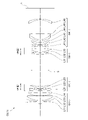
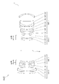
- FIG. 1 is a diagram showing a lens configuration of an optical system according to the first embodiment.
- the optical system OL (1) according to the first embodiment has a first lens group G1 having a positive refractive power and a second lens group G2 having a negative refractive power arranged in order from the object side along the optical axis.
- the second lens group G2 moves to the image side along the optical axis
- the third lens group G3 moves to the object side along the optical axis and is adjacent to each other.
- the distance between each lens group changes.
- the positions of the first lens group G1 and the fourth lens group G4 are fixed with respect to the image plane I.
- the aperture stop S is arranged between the second lens group G2 and the third lens group G3.
- the position of the aperture stop S is fixed with respect to the image plane I.
- the symbol (+) or ( ⁇ ) attached to each lens group symbol indicates the refractive power of each lens group, and this also applies to all the following examples.
- the first lens group G1 includes a biconvex positive lens L11 arranged in order from the object side along the optical axis, a negative meniscus lens L12 having a convex surface facing the object side, and a positive meniscus lens L12 having a convex surface facing the object side. It is composed of a bonded lens to which L13 is bonded and a positive meniscus lens L14 having a convex surface facing the object side.
- the negative meniscus lens L12 of the first lens group G1 corresponds to a negative lens satisfying the conditional expressions (4) to (6).
- the second lens group G2 includes a biconcave negative lens L21 arranged in order from the object side along the optical axis, a negative meniscus lens L22 having a convex surface facing the object side, and a positive meniscus lens L22 having a convex surface facing the object side. It is composed of a bonded lens to which L23 is bonded and a bonded lens.
- a biconvex positive lens L31 arranged in order from the object side along the optical axis, a negative meniscus lens L32 having a convex surface facing the object side, and a biconvex positive lens L33 are joined. It is composed of a bonded lens and a lens.
- the negative meniscus lens L32 of the third lens group G3 corresponds to a negative lens satisfying the conditional expressions (17) to (19).
- the fourth lens group G4 has a negative meniscus lens L41 having a convex surface facing the object side, a negative meniscus lens L42 having a convex surface facing the object side, and a convex surface facing the object side, arranged in order from the object side along the optical axis.
- a bonded lens to which a positive meniscus lens L43 is bonded, a bonded lens to which a negative meniscus lens L44 having a convex surface facing the object side and a positive meniscus lens L45 having a convex surface facing the object side are bonded, and a concave surface to the object side. It is composed of a negative meniscus lens L46, which is directed toward the lens.
- the negative meniscus lens L46 has an aspherical lens surface on the object side.
- the image plane I is arranged on the image side of the fourth lens group G4.
- Table 1 below lists the values of the specifications of the optical system according to the first embodiment.
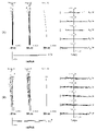
- FIG. 2A is a diagram of various aberrations in the infinity-focused state of the optical system according to the first embodiment.
- FNO indicates an F number
- Y indicates an image height.
- NA indicates the numerical aperture
- Y indicates the image height.
- the spherical aberration diagram shows the value of the F number or numerical aperture corresponding to the maximum aperture
- the astigmatism diagram and the distortion diagram show the maximum image height
- the coma aberration diagram shows the value of each image height. ..
- the solid line shows the sagittal image plane and the broken line shows the meridional image plane.
- the same reference numerals as those of the present embodiment are used, and duplicate description is omitted.
- the optical system according to the first embodiment has excellent imaging performance in which various aberrations are satisfactorily corrected in the entire range from the infinity focusing state to the closest distance focusing state. You can see that there is.
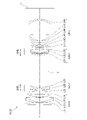
- FIG. 3 is a diagram showing a lens configuration of an optical system according to a second embodiment.
- the optical system OL (2) according to the second embodiment has a first lens group G1 having a positive refractive power and a second lens group G2 having a negative refractive power arranged in order from the object side along the optical axis.
- the second lens group G2 moves to the image side along the optical axis
- the third lens group G3 moves to the object side along the optical axis and is adjacent to each other.
- the distance between each lens group changes.
- the positions of the first lens group G1 and the fourth lens group G4 are fixed with respect to the image plane I.
- the aperture stop S is arranged between the second lens group G2 and the third lens group G3. At the time of focusing, the position of the aperture stop S is fixed with respect to the image plane I.
- the first lens group G1 includes a positive meniscus lens L11 having a concave surface facing the object side, a negative meniscus lens L12 having a convex surface facing the object side, and a convex surface facing the object side, arranged in order from the object side along the optical axis. It is composed of a bonded lens to which the positive meniscus lens L13 is bonded and a regular meniscus lens L14 having a convex surface facing the object side.
- the negative meniscus lens L12 of the first lens group G1 corresponds to a negative lens satisfying the conditional expressions (4) to (6).
- the negative meniscus lens L32 of the third lens group G3 corresponds to a negative lens satisfying the conditional expressions (17) to (19).
- Table 2 below lists the values of the specifications of the optical system according to the second embodiment.
- FIG. 4A is a diagram of various aberrations in the infinity-focused state of the optical system according to the second embodiment.
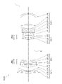
- FIG. 5 is a diagram showing a lens configuration of an optical system according to a third embodiment.
- the optical system OL (3) according to the third embodiment has a first lens group G1 having a positive refractive power and a second lens group G2 having a negative refractive power arranged in order from the object side along the optical axis.
- the second lens group G2 moves to the image side along the optical axis
- the third lens group G3 moves to the object side along the optical axis and is adjacent to each other.
- the distance between each lens group changes.
- the positions of the first lens group G1 and the fourth lens group G4 are fixed with respect to the image plane I.
- the aperture stop S is arranged between the second lens group G2 and the third lens group G3. At the time of focusing, the position of the aperture stop S is fixed with respect to the image plane I.
- the first lens group G1 includes a biconvex positive lens L11 arranged in order from the object side along the optical axis, a negative meniscus lens L12 having a convex surface facing the object side, and a positive meniscus lens L12 having a convex surface facing the object side. It is composed of a bonded lens to which L13 is bonded and a positive meniscus lens L14 having a convex surface facing the object side.
- the positive meniscus lens L14 has an aspherical lens surface on the object side.
- the negative meniscus lens L12 of the first lens group G1 corresponds to a negative lens satisfying the conditional expressions (4) to (6).
- the negative meniscus lens L32 of the third lens group G3 corresponds to a negative lens satisfying the conditional expressions (17) to (19).
- Table 3 below lists the values of the specifications of the optical system according to the third embodiment.
- FIG. 6A is a diagram of various aberrations in the infinity-focused state of the optical system according to the third embodiment.
- FIG. 7 is a diagram showing a lens configuration of an optical system according to a fourth embodiment.
- the optical system OL (4) according to the fourth embodiment has a first lens group G1 having a positive refractive power and a second lens group G2 having a negative refractive power arranged in order from the object side along the optical axis.
- the second lens group G2 moves to the image side along the optical axis
- the third lens group G3 moves to the object side along the optical axis and is adjacent to each other.
- the distance between each lens group changes.
- the positions of the first lens group G1 and the fourth lens group G4 are fixed with respect to the image plane I.
- the aperture stop S is arranged between the second lens group G2 and the third lens group G3. At the time of focusing, the position of the aperture stop S is fixed with respect to the image plane I.
- the second lens group G2 and the third lens group G3 are configured in the same manner as in the first embodiment, the same reference numerals as in the case of the first embodiment are assigned to each of these lenses. A detailed description will be omitted.
- a biconvex positive lens L11 arranged in order from the object side along the optical axis, a negative meniscus lens L12 with a convex surface facing the object side, and a biconvex positive lens L13 are joined. It is composed of a bonded lens and a positive meniscus lens L14 having a convex surface facing the object side.
- the positive meniscus lens L14 has an aspherical lens surface on the object side.
- the negative meniscus lens L12 of the first lens group G1 corresponds to a negative lens satisfying the conditional expressions (4) to (6).
- the negative meniscus lens L32 of the third lens group G3 corresponds to a negative lens satisfying the conditional expressions (17) to (19).
- the fourth lens group G4 includes a biconcave negative lens L41 arranged in order from the object side along the optical axis, a negative meniscus lens L42 having a convex surface facing the object side, and a positive meniscus lens L42 having a convex surface facing the object side.
- the negative meniscus lens L46 has an aspherical lens surface on the object side.
- the image plane I is arranged on the image side of the fourth lens group G4.
- Table 4 lists the values of the specifications of the optical system according to the fourth embodiment.
- FIG. 8A is a diagram of various aberrations in the infinity-focused state of the optical system according to the fourth embodiment.
- FIG. 9 is a diagram showing a lens configuration of an optical system according to a fifth embodiment.
- the optical system OL (5) according to the fifth embodiment has a first lens group G1 having a positive refractive power and a second lens group G2 having a negative refractive power arranged in order from the object side along the optical axis. , A third lens group G3 having a positive refractive power, and a fourth lens group G4 having a negative refractive power.
- the second lens group G2 moves to the image side along the optical axis
- the third lens group G3 moves to the object side along the optical axis and is adjacent to each other.
- the distance between each lens group changes.
- the positions of the first lens group G1 and the fourth lens group G4 are fixed with respect to the image plane I.
- the aperture stop S is arranged between the second lens group G2 and the third lens group G3. At the time of focusing, the position of the aperture stop S is fixed with respect to the image plane I.
- the second lens group G2 and the third lens group G3 are configured in the same manner as in the first embodiment, the same reference numerals as in the case of the first embodiment are assigned to each of these lenses. A detailed description will be omitted.
- a biconvex positive lens L11 arranged in order from the object side along the optical axis, a negative meniscus lens L12 with a convex surface facing the object side, and a biconvex positive lens L13 are joined. It is composed of a bonded lens and a positive meniscus lens L14 having a convex surface facing the object side.
- the negative meniscus lens L12 of the first lens group G1 corresponds to a negative lens satisfying the conditional expressions (4) to (6).
- the negative meniscus lens L32 of the third lens group G3 corresponds to a negative lens satisfying the conditional expressions (17) to (19).
- the fourth lens group G4 has a negative meniscus lens L41 having a convex surface facing the object side, a negative meniscus lens L42 having a convex surface facing the object side, and a convex surface facing the object side, arranged in order from the object side along the optical axis.
- a bonded lens to which a positive meniscus lens L43 is bonded, a positive meniscus lens L44 having a convex surface facing the object side, a negative meniscus lens L45 having a convex surface facing the object side, and a biconvex positive lens L46 are bonded. It is composed of a bonded lens and a negative meniscus lens L47 with a concave surface facing the object side.
- the negative meniscus lens L47 has an aspherical lens surface on the object side.
- the image plane I is arranged on the image side of the fourth lens group G4.
- Table 5 lists the values of the specifications of the optical system according to the fifth embodiment.
- FIG. 10A is a diagram of various aberrations of the optical system according to the fifth embodiment in the infinity in-focus state.
- Conditional expression (1) 0.20 ⁇ DG4 / TL ⁇ 0.40
- Conditional expression (2) 3.00 ⁇ (LnR2 + LnR1) / (LnR2-LnR1) ⁇ 5.00
- Conditional expression (3) 0.75 ⁇ f1 / (-f2) ⁇ 1.
- Conditional expression (4) 1.80 ⁇ ndM1
- Conditional expression (5) ⁇ dM1 ⁇ 26.00
- Conditional expression (6) ⁇ gFM1- (0.6415-0.00162 ⁇ ⁇ dM1) ⁇ 0.0120
- Conditional expression (7) 0.75 ⁇ f1 / f3 ⁇ 1.20
- Conditional expression (8) 0.45 ⁇ (- ⁇ )
- Conditional expression (9) 35.0 ⁇ 2 / ⁇ 3 ⁇ 350.0
- Conditional expression (10) 0.005 ⁇ 3 / ⁇ 2 ⁇ 0.035
- a four-group configuration is shown, but the present application is not limited to this, and an optical system having another group configuration (for example, five groups, etc.) can also be configured.
- a lens or a lens group may be added to the most object side or the most image plane side of the optical system of the present embodiment.
- the lens group refers to a portion having at least one lens separated by an air interval that changes at the time of focusing.
- the lens group or partial lens group is moved so as to have a component in the direction perpendicular to the optical axis, or is rotationally moved (swinged) in the in-plane direction including the optical axis to correct image blur caused by camera shake. It may be used as an anti-vibration lens group.
- the lens surface may be formed of a spherical surface or a flat surface, or may be formed of an aspherical surface.
- lens processing and assembly adjustment are facilitated, and deterioration of optical performance due to processing and assembly adjustment errors can be prevented, which is preferable. Further, even if the image plane is displaced, the deterioration of the depiction performance is small, which is preferable.
- the aspherical surface is an aspherical surface formed by grinding, a glass mold aspherical surface formed by forming glass into an aspherical surface shape, or a composite aspherical surface formed by forming resin on the glass surface into an aspherical surface shape. It doesn't matter which one. Further, the lens surface may be a diffraction surface, and the lens may be a refractive index distribution type lens (GRIN lens) or a plastic lens.
- GRIN lens refractive index distribution type lens
- the aperture diaphragm is preferably arranged between the second lens group and the third lens group, but the role may be substituted by the frame of the lens without providing the member as the aperture diaphragm.
- Each lens surface may be provided with an antireflection film having high transmittance in a wide wavelength range in order to reduce flare and ghost and achieve high contrast optical performance.
- G1 1st lens group G2 2nd lens group G3 3rd lens group G4 4th lens group I image plane S aperture stop
Landscapes
- Physics & Mathematics (AREA)
- General Physics & Mathematics (AREA)
- Optics & Photonics (AREA)
- Lenses (AREA)
Abstract
光学系(OL)は、光軸に沿って物体側から順に並んだ、正の屈折力を有する第1レンズ群(G1)と、負の屈折力を有する第2レンズ群(G2)と、正の屈折力を有する第3レンズ群(G3)と、負の屈折力を有する第4レンズ群(G4)とを有し、合焦の際、第2レンズ群(G2)と第3レンズ群(G3)とが光軸に沿って移動し、隣り合う各レンズ群の間隔が変化し、以下の条件式を満足する。 0.20<DG4/TL<0.40 但し、DG4:第4レンズ群(G4)の光軸上の長さ TL:無限遠合焦状態での光学系(OL)の全長
Description
本発明は、光学系、光学機器、および光学系の製造方法に関する。
従来から、複数のレンズ群を光軸に沿って移動させて合焦を行う光学系が提案されている(例えば、特許文献1を参照)。このような光学系においては、合焦の際の収差変動を抑えることが難しい。
第1の本発明に係る光学系は、光軸に沿って物体側から順に並んだ、正の屈折力を有する第1レンズ群と、負の屈折力を有する第2レンズ群と、正の屈折力を有する第3レンズ群と、負の屈折力を有する第4レンズ群とを有し、合焦の際、前記第2レンズ群と前記第3レンズ群とが光軸に沿って移動し、隣り合う各レンズ群の間隔が変化し、以下の条件式を満足する。
0.20<DG4/TL<0.40
但し、DG4:前記第4レンズ群の光軸上の長さ
TL:無限遠合焦状態での前記光学系の全長
0.20<DG4/TL<0.40
但し、DG4:前記第4レンズ群の光軸上の長さ
TL:無限遠合焦状態での前記光学系の全長
第2の本発明に係る光学系は、光軸に沿って物体側から順に並んだ、正の屈折力を有する第1レンズ群と、負の屈折力を有する第2レンズ群と、正の屈折力を有する第3レンズ群と、負の屈折力を有する第4レンズ群とを有し、合焦の際、前記第2レンズ群と前記第3レンズ群とが光軸に沿って移動し、隣り合う各レンズ群の間隔が変化し、以下の条件式を満足する。
3.00<(LnR2+LnR1)/(LnR2-LnR1)<5.00
但し、LnR1:前記光学系の最も像側に配置された負レンズにおける物体側のレンズ面の曲率半径
LnR2:前記光学系の最も像側に配置された負レンズにおける像側のレンズ面の曲率半径
3.00<(LnR2+LnR1)/(LnR2-LnR1)<5.00
但し、LnR1:前記光学系の最も像側に配置された負レンズにおける物体側のレンズ面の曲率半径
LnR2:前記光学系の最も像側に配置された負レンズにおける像側のレンズ面の曲率半径
第3の本発明に係る光学系は、光軸に沿って物体側から順に並んだ、正の屈折力を有する第1レンズ群と、負の屈折力を有する第2レンズ群と、正の屈折力を有する第3レンズ群と、負の屈折力を有する第4レンズ群とを有し、合焦の際、前記第2レンズ群と前記第3レンズ群とが光軸に沿って移動し、隣り合う各レンズ群の間隔が変化し、以下の条件式を満足する。
0.75<f1/(-f2)<1.30
但し、f1:前記第1レンズ群の焦点距離
f2:前記第2レンズ群の焦点距離
0.75<f1/(-f2)<1.30
但し、f1:前記第1レンズ群の焦点距離
f2:前記第2レンズ群の焦点距離
第4の本発明に係る光学系は、光軸に沿って物体側から順に並んだ、正の屈折力を有する第1レンズ群と、負の屈折力を有する第2レンズ群と、正の屈折力を有する第3レンズ群と、負の屈折力を有する第4レンズ群とを有し、合焦の際、前記第2レンズ群と前記第3レンズ群とが光軸に沿って移動し、隣り合う各レンズ群の間隔が変化し、前記第1レンズ群が以下の条件式を満足する負レンズを有する。
1.80<ndM1
νdM1<26.00
θgFM1-(0.6415-0.00162×νdM1)<0.0120
但し、ndM1:前記第1レンズ群の前記負レンズのd線に対する屈折率
νdM1:前記第1レンズ群の前記負レンズのアッベ数
θgFM1:前記第1レンズ群の前記負レンズの部分分散比であり、前記第1レンズ群の前記負レンズのg線に対する屈折率をngM1とし、前記第1レンズ群の前記負レンズのF線に対する屈折率をnFM1とし、前記第1レンズ群の前記負レンズのC線に対する屈折率をnCM1としたとき、次式で定義される
θgFM1=(ngM1-nFM1)/(nFM1-nCM1)
1.80<ndM1
νdM1<26.00
θgFM1-(0.6415-0.00162×νdM1)<0.0120
但し、ndM1:前記第1レンズ群の前記負レンズのd線に対する屈折率
νdM1:前記第1レンズ群の前記負レンズのアッベ数
θgFM1:前記第1レンズ群の前記負レンズの部分分散比であり、前記第1レンズ群の前記負レンズのg線に対する屈折率をngM1とし、前記第1レンズ群の前記負レンズのF線に対する屈折率をnFM1とし、前記第1レンズ群の前記負レンズのC線に対する屈折率をnCM1としたとき、次式で定義される
θgFM1=(ngM1-nFM1)/(nFM1-nCM1)
本発明に係る光学機器は、上記光学系を備えて構成される。
第1の本発明に係る光学系の製造方法は、光軸に沿って物体側から順に並んだ、正の屈折力を有する第1レンズ群と、負の屈折力を有する第2レンズ群と、正の屈折力を有する第3レンズ群と、負の屈折力を有する第4レンズ群とを有する光学系の製造方法であって、合焦の際、前記第2レンズ群と前記第3レンズ群とが光軸に沿って移動し、隣り合う各レンズ群の間隔が変化し、以下の条件式を満足するように、レンズ鏡筒内に各レンズを配置する。
0.20<DG4/TL<0.40
但し、DG4:前記第4レンズ群の光軸上の長さ
TL:無限遠合焦状態での前記光学系の全長
0.20<DG4/TL<0.40
但し、DG4:前記第4レンズ群の光軸上の長さ
TL:無限遠合焦状態での前記光学系の全長
第2の本発明に係る光学系の製造方法は、光軸に沿って物体側から順に並んだ、正の屈折力を有する第1レンズ群と、負の屈折力を有する第2レンズ群と、正の屈折力を有する第3レンズ群と、負の屈折力を有する第4レンズ群とを有する光学系の製造方法であって、合焦の際、前記第2レンズ群と前記第3レンズ群とが光軸に沿って移動し、隣り合う各レンズ群の間隔が変化し、以下の条件式を満足するように、レンズ鏡筒内に各レンズを配置する。
3.00<(LnR2+LnR1)/(LnR2-LnR1)<5.00
但し、LnR1:前記光学系の最も像側に配置された負レンズにおける物体側のレンズ面の曲率半径
LnR2:前記光学系の最も像側に配置された負レンズにおける像側のレンズ面の曲率半径
3.00<(LnR2+LnR1)/(LnR2-LnR1)<5.00
但し、LnR1:前記光学系の最も像側に配置された負レンズにおける物体側のレンズ面の曲率半径
LnR2:前記光学系の最も像側に配置された負レンズにおける像側のレンズ面の曲率半径
第3の本発明に係る光学系の製造方法は、光軸に沿って物体側から順に並んだ、正の屈折力を有する第1レンズ群と、負の屈折力を有する第2レンズ群と、正の屈折力を有する第3レンズ群と、負の屈折力を有する第4レンズ群とを有する光学系の製造方法であって、合焦の際、前記第2レンズ群と前記第3レンズ群とが光軸に沿って移動し、隣り合う各レンズ群の間隔が変化し、以下の条件式を満足するように、レンズ鏡筒内に各レンズを配置する。
0.75<f1/(-f2)<1.30
但し、f1:前記第1レンズ群の焦点距離
f2:前記第2レンズ群の焦点距離
0.75<f1/(-f2)<1.30
但し、f1:前記第1レンズ群の焦点距離
f2:前記第2レンズ群の焦点距離
第4の本発明に係る光学系の製造方法は、光軸に沿って物体側から順に並んだ、正の屈折力を有する第1レンズ群と、負の屈折力を有する第2レンズ群と、正の屈折力を有する第3レンズ群と、負の屈折力を有する第4レンズ群とを有する光学系の製造方法であって、合焦の際、前記第2レンズ群と前記第3レンズ群とが光軸に沿って移動し、隣り合う各レンズ群の間隔が変化し、前記第1レンズ群が以下の条件式を満足する負レンズを有するように、レンズ鏡筒内に各レンズを配置する。
1.80<ndM1
νdM1<26.00
θgFM1-(0.6415-0.00162×νdM1)<0.0120
但し、ndM1:前記第1レンズ群の前記負レンズのd線に対する屈折率
νdM1:前記第1レンズ群の前記負レンズのアッベ数
θgFM1:前記第1レンズ群の前記負レンズの部分分散比であり、前記第1レンズ群の前記負レンズのg線に対する屈折率をngM1とし、前記第1レンズ群の前記負レンズのF線に対する屈折率をnFM1とし、前記第1レンズ群の前記負レンズのC線に対する屈折率をnCM1としたとき、次式で定義される
θgFM1=(ngM1-nFM1)/(nFM1-nCM1)
1.80<ndM1
νdM1<26.00
θgFM1-(0.6415-0.00162×νdM1)<0.0120
但し、ndM1:前記第1レンズ群の前記負レンズのd線に対する屈折率
νdM1:前記第1レンズ群の前記負レンズのアッベ数
θgFM1:前記第1レンズ群の前記負レンズの部分分散比であり、前記第1レンズ群の前記負レンズのg線に対する屈折率をngM1とし、前記第1レンズ群の前記負レンズのF線に対する屈折率をnFM1とし、前記第1レンズ群の前記負レンズのC線に対する屈折率をnCM1としたとき、次式で定義される
θgFM1=(ngM1-nFM1)/(nFM1-nCM1)
以下、本発明に係る好ましい実施形態について説明する。まず、各実施形態に係る光学系を備えたカメラ(光学機器)を図11に基づいて説明する。このカメラ1は、図11に示すように、本体2と、本体2に装着される撮影レンズ3により構成される。本体2は、撮像素子4と、デジタルカメラの動作を制御する本体制御部(不図示)と、液晶画面5とを備える。撮影レンズ3は、複数のレンズ群からなる光学系OLと、各レンズ群の位置を制御するレンズ位置制御機構(不図示)とを備える。レンズ位置制御機構は、レンズ群の位置を検出するセンサと、レンズ群を光軸に沿って前後に移動させるモータと、モータを駆動する制御回路などにより構成される。
被写体からの光は、撮影レンズ3の光学系OLにより集光されて、撮像素子4の像面I上に到達する。像面Iに到達した被写体からの光は、撮像素子4により光電変換され、デジタル画像データとして不図示のメモリに記録される。メモリに記録されたデジタル画像データは、ユーザの操作に応じて液晶画面5に表示することが可能である。なお、このカメラは、ミラーレスカメラでも、クイックリターンミラーを有した一眼レフタイプのカメラであっても良い。また、図11に示す光学系OLは、撮影レンズ3に備えられる光学系を模式的に示したものであり、光学系OLのレンズ構成はこの構成に限定されるものではない。
次に、第1実施形態に係る光学系について説明する。第1実施形態に係る光学系OLの一例としての光学系OL(1)は、図1に示すように、光軸に沿って物体側から順に並んだ、正の屈折力を有する第1レンズ群G1と、負の屈折力を有する第2レンズ群G2と、正の屈折力を有する第3レンズ群G3と、負の屈折力を有する第4レンズ群G4とを有して構成される。合焦の際、第2レンズ群G2と第3レンズ群G3とが光軸に沿って移動し、隣り合う各レンズ群の間隔が変化する。
上記構成の下、第1実施形態に係る光学系OLは、以下の条件式(1)を満足する。
0.20<DG4/TL<0.40 ・・・(1)
但し、DG4:第4レンズ群G4の光軸上の長さ
TL:無限遠合焦状態での光学系OLの全長
0.20<DG4/TL<0.40 ・・・(1)
但し、DG4:第4レンズ群G4の光軸上の長さ
TL:無限遠合焦状態での光学系OLの全長
第1実施形態によれば、合焦の際の収差変動が少ない光学系、およびこの光学系を備えた光学機器を得ることが可能になる。第1実施形態に係る光学系OLは、図3に示す光学系OL(2)でも良く、図5に示す光学系OL(3)でも良く、図7に示す光学系OL(4)でも良く、図9に示す光学系OL(5)でも良い。
条件式(1)は、第4レンズ群G4の光軸上の長さと光学系OLの全長との適切な関係を規定するものである。条件式(1)を満足することで、光学系OLの全長に対する第4レンズ群G4の光軸上の長さが大きくなるため、倍率の範囲の全域において、周辺部における像面湾曲とコマ収差を良好に補正することができる。なお、各実施形態において、光学系OLの全長は、光学系OLの最も物体側のレンズ面から像面Iまでの光軸上の距離(なお、光学系OLの最も像側のレンズ面から像面Iまでの距離は空気換算距離)とする。
条件式(1)の対応値が上記範囲を外れてしまうと、倍率の範囲の一部で周辺部における像面湾曲とコマ収差を補正することが困難になる。条件式(1)の下限値を、0.21、0.23、さらに0.25に設定することで、本実施形態の効果をより確実なものとすることができる。また、条件式(1)の上限値を、0.38、0.36、0.35、さらに0.33に設定することで、本実施形態の効果をより確実なものとすることができる。
次に、第2実施形態に係る光学系について説明する。第2実施形態に係る光学系は、第1実施形態に係る光学系OLと同様の構成であるため、第1実施形態と同一の符号を付して説明する。第2実施形態に係る光学系OLの一例としての光学系OL(1)は、図1に示すように、光軸に沿って物体側から順に並んだ、正の屈折力を有する第1レンズ群G1と、負の屈折力を有する第2レンズ群G2と、正の屈折力を有する第3レンズ群G3と、負の屈折力を有する第4レンズ群G4とを有して構成される。合焦の際、第2レンズ群G2と第3レンズ群G3とが光軸に沿って移動し、隣り合う各レンズ群の間隔が変化する。
上記構成の下、第2実施形態に係る光学系OLは、以下の条件式(2)を満足する。
3.00<(LnR2+LnR1)/(LnR2-LnR1)<5.00 ・・・(2)
但し、LnR1:光学系OLの最も像側に配置された負レンズにおける物体側のレンズ面の曲率半径
LnR2:光学系OLの最も像側に配置された負レンズにおける像側のレンズ面の曲率半径
3.00<(LnR2+LnR1)/(LnR2-LnR1)<5.00 ・・・(2)
但し、LnR1:光学系OLの最も像側に配置された負レンズにおける物体側のレンズ面の曲率半径
LnR2:光学系OLの最も像側に配置された負レンズにおける像側のレンズ面の曲率半径
第2実施形態によれば、合焦の際の収差変動が少ない光学系、およびこの光学系を備えた光学機器を得ることが可能になる。第2実施形態に係る光学系OLは、図3に示す光学系OL(2)でも良く、図5に示す光学系OL(3)でも良く、図7に示す光学系OL(4)でも良く、図9に示す光学系OL(5)でも良い。
条件式(2)は、光学系OLの最も像側に配置された負レンズのシェイプファクターについて適切な範囲を規定するものである。条件式(2)を満足することで、倍率の範囲の全域において、像面湾曲とコマ収差を像面内で均一に補正することができる。
条件式(2)の対応値が上記範囲を外れてしまうと、倍率の範囲の一部で像面湾曲とコマ収差を像面内で均一に補正することが困難になる。条件式(2)の下限値を、3.05、3.10、3.15、3.20、さらに3.23に設定することで、本実施形態の効果をより確実なものとすることができる。また、条件式(2)の上限値を、4.90、4.80、4.70、4.60、4.50、さらに4.40に設定することで、本実施形態の効果をより確実なものとすることができる。
次に、第3実施形態に係る光学系について説明する。第3実施形態に係る光学系は、第1実施形態に係る光学系OLと同様の構成であるため、第1実施形態と同一の符号を付して説明する。第3実施形態に係る光学系OLの一例としての光学系OL(1)は、図1に示すように、光軸に沿って物体側から順に並んだ、正の屈折力を有する第1レンズ群G1と、負の屈折力を有する第2レンズ群G2と、正の屈折力を有する第3レンズ群G3と、負の屈折力を有する第4レンズ群G4とを有して構成される。合焦の際、第2レンズ群G2と第3レンズ群G3とが光軸に沿って移動し、隣り合う各レンズ群の間隔が変化する。
上記構成の下、第3実施形態に係る光学系OLは、以下の条件式(3)を満足する。
0.75<f1/(-f2)<1.30 ・・・(3)
但し、f1:第1レンズ群G1の焦点距離
f2:第2レンズ群G2の焦点距離
0.75<f1/(-f2)<1.30 ・・・(3)
但し、f1:第1レンズ群G1の焦点距離
f2:第2レンズ群G2の焦点距離
第3実施形態によれば、合焦の際の収差変動が少ない光学系、およびこの光学系を備えた光学機器を得ることが可能になる。第3実施形態に係る光学系OLは、図3に示す光学系OL(2)でも良く、図5に示す光学系OL(3)でも良く、図7に示す光学系OL(4)でも良く、図9に示す光学系OL(5)でも良い。
条件式(3)は、第1レンズ群G1の焦点距離と第2レンズ群G2の焦点距離との適切な関係を規定するものである。条件式(3)を満足することで、無限遠物体から近距離物体への合焦の際の球面収差と像面湾曲の変動を抑えることができる。
条件式(3)の対応値が上記範囲を外れてしまうと、合焦の際の球面収差と像面湾曲の変動を抑えることが困難になる。条件式(3)の下限値を、0.80、0.90、0.95、1.00、1.05、さらに1.10に設定することで、本実施形態の効果をより確実なものとすることができる。また、条件式(3)の上限値を、1.28、1.25、1.23、さらに1.20に設定することで、本実施形態の効果をより確実なものとすることができる。
次に、第4実施形態に係る光学系について説明する。第4実施形態に係る光学系は、第1実施形態に係る光学系OLと同様の構成であるため、第1実施形態と同一の符号を付して説明する。第4実施形態に係る光学系OLの一例としての光学系OL(1)は、図1に示すように、光軸に沿って物体側から順に並んだ、正の屈折力を有する第1レンズ群G1と、負の屈折力を有する第2レンズ群G2と、正の屈折力を有する第3レンズ群G3と、負の屈折力を有する第4レンズ群G4とを有して構成される。合焦の際、第2レンズ群G2と第3レンズ群G3とが光軸に沿って移動し、隣り合う各レンズ群の間隔が変化する。
上記構成の下、第4実施形態に係る光学系OLは、以下の条件式(4)~(6)を満足する。
1.80<ndM1 ・・・(4)
νdM1<26.00 ・・・(5)
θgFM1-(0.6415-0.00162×νdM1)<0.0120 ・・・(6)
但し、ndM1:第1レンズ群G1の負レンズのd線に対する屈折率
νdM1:第1レンズ群G1の負レンズのアッベ数
θgFM1:第1レンズ群G1の負レンズの部分分散比であり、第1レンズ群G1の負レンズのg線に対する屈折率をngM1とし、第1レンズ群G1の負レンズのF線に対する屈折率をnFM1とし、第1レンズ群G1の負レンズのC線に対する屈折率をnCM1としたとき、次式で定義される
θgFM1=(ngM1-nFM1)/(nFM1-nCM1)
1.80<ndM1 ・・・(4)
νdM1<26.00 ・・・(5)
θgFM1-(0.6415-0.00162×νdM1)<0.0120 ・・・(6)
但し、ndM1:第1レンズ群G1の負レンズのd線に対する屈折率
νdM1:第1レンズ群G1の負レンズのアッベ数
θgFM1:第1レンズ群G1の負レンズの部分分散比であり、第1レンズ群G1の負レンズのg線に対する屈折率をngM1とし、第1レンズ群G1の負レンズのF線に対する屈折率をnFM1とし、第1レンズ群G1の負レンズのC線に対する屈折率をnCM1としたとき、次式で定義される
θgFM1=(ngM1-nFM1)/(nFM1-nCM1)
第4実施形態によれば、合焦の際の収差変動が少ない光学系、およびこの光学系を備えた光学機器を得ることが可能になる。第4実施形態に係る光学系OLは、図3に示す光学系OL(2)でも良く、図5に示す光学系OL(3)でも良く、図7に示す光学系OL(4)でも良く、図9に示す光学系OL(5)でも良い。
条件式(4)は、第1レンズ群G1の負レンズのd線に対する屈折率について適切な範囲を規定するものである。条件式(5)は、第1レンズ群G1の負レンズのアッベ数について適切な範囲を規定するものである。条件式(6)は、第1レンズ群G1の負レンズの部分分散比とアッベ数の適切な関係を規定するものである。条件式(4)~(6)を満足することで、倍率の範囲の全域において、軸上色収差および倍率色収差を良好に補正することができる。
条件式(4)の対応値が上記範囲を外れてしまうと、倍率の範囲の一部で軸上色収差および倍率色収差を補正することが困難になる。条件式(4)の下限値を、1.82、1.83、さらに1.84に設定することで、本実施形態の効果をより確実なものとすることができる。
条件式(5)の対応値が上記範囲を外れてしまうと、倍率の範囲の一部で軸上色収差および倍率色収差を補正することが困難になる。条件式(5)の上限値を、25.90、25.85、25.70、25.50、さらに25.35に設定することで、本実施形態の効果をより確実なものとすることができる。
条件式(6)の対応値が上記範囲を外れてしまうと、倍率の範囲の一部で軸上色収差および倍率色収差を補正することが困難になる。条件式(6)の上限値を、0.0115、0.0110、0.0105、0.0100、さらに0.0098に設定することで、本実施形態の効果をより確実なものとすることができる。また、条件式(6)の下限を0.0000より大きいとしてもよい。
第2~第4実施形態に係る光学系OLは、前述の条件式(1)を満足することが望ましい。条件式(1)を満足することで、第1実施形態と同様、倍率の範囲の全域において、周辺部における像面湾曲とコマ収差を良好に補正することができる。条件式(1)の下限値を、0.21、0.23、さらに0.25に設定することで、各実施形態の効果をより確実なものとすることができる。また、条件式(1)の上限値を、0.38、0.36、0.35、さらに0.33に設定することで、各実施形態の効果をより確実なものとすることができる。
第3実施形態および第4実施形態に係る光学系OLは、前述の条件式(2)を満足することが望ましい。条件式(2)を満足することで、第2実施形態と同様、倍率の範囲の全域において、像面湾曲とコマ収差を像面内で均一に補正することができる。条件式(2)の下限値を、3.05、3.10、3.15、3.20、さらに3.23に設定することで、各実施形態の効果をより確実なものとすることができる。また、条件式(2)の上限値を、4.90、4.80、4.70、4.60、4.50、さらに4.40に設定することで、各実施形態の効果をより確実なものとすることができる。
第4実施形態に係る光学系OLは、前述の条件式(3)を満足することが望ましい。条件式(3)を満足することで、第3実施形態と同様、無限遠物体から近距離物体への合焦の際の球面収差と像面湾曲の変動を抑えることができる。条件式(3)の下限値を、0.80、0.90、0.95、1.00、1.05、さらに1.10に設定することで、本実施形態の効果をより確実なものとすることができる。また、条件式(3)の上限値を、1.28、1.25、1.23、さらに1.20に設定することで、本実施形態の効果をより確実なものとすることができる。
第1~第4実施形態に係る光学系OLは、以下の条件式(7)を満足することが望ましい。
0.75<f1/f3<1.20 ・・・(7)
但し、f1:第1レンズ群G1の焦点距離
f3:第3レンズ群G3の焦点距離
0.75<f1/f3<1.20 ・・・(7)
但し、f1:第1レンズ群G1の焦点距離
f3:第3レンズ群G3の焦点距離
条件式(7)は、第1レンズ群G1の焦点距離と第3レンズ群G3の焦点距離との適切な関係を規定するものである。条件式(7)を満足することで、無限遠物体から近距離物体への合焦の際の球面収差と像面湾曲の変動を抑えることができる。
条件式(7)の対応値が上記範囲を外れてしまうと、合焦の際の球面収差と像面湾曲の変動を抑えることが困難になる。条件式(7)の下限値を、0.80、0.85、0.90、0.95、さらに1.00に設定することで、各実施形態の効果をより確実なものとすることができる。また、条件式(7)の上限値を、1.18、1.15、1.13、さらに1.10に設定することで、各実施形態の効果をより確実なものとすることができる。
第1~第4実施形態に係る光学系OLは、以下の条件式(8)を満足することが望ましい。
0.45<(-β) ・・・(8)
但し、β:光学系OLの横倍率
0.45<(-β) ・・・(8)
但し、β:光学系OLの横倍率
条件式(8)は、光学系OL全系の横倍率について適切な範囲を規定するものである。条件式(8)を満足することで、至近距離での撮影が可能であるため好ましい。条件式(8)の下限値を、0.52、0.55、0.60、0.70、0.75、さらに0.80に設定することで、各実施形態の効果をより確実なものとすることができる。
第1~第4実施形態に係る光学系OLは、以下の条件式(9)を満足することが望ましい。
35.0<β2/β3<350.0 ・・・(9)
但し、β2:無限遠合焦状態での第2レンズ群G2の横倍率
β3:無限遠合焦状態での第3レンズ群G3の横倍率
35.0<β2/β3<350.0 ・・・(9)
但し、β2:無限遠合焦状態での第2レンズ群G2の横倍率
β3:無限遠合焦状態での第3レンズ群G3の横倍率
条件式(9)は、無限遠合焦状態での第2レンズ群G2の横倍率と、無限遠合焦状態での第3レンズ群G3の横倍率との適切な関係を規定するものである。条件式(9)を満足することで、合焦の際の像面湾曲と球面収差の変動を抑えることができる。
条件式(9)の対応値が上記範囲を外れてしまうと、合焦の際の像面湾曲と球面収差の変動を抑えることが困難になる。条件式(9)の下限値を、35.50、36.00、36.50、37.00、さらに37.30に設定することで、各実施形態の効果をより確実なものとすることができる。また、条件式(9)の上限値を、300.00、250.00、200.00、150.00、100.00、85.00、さらに75.00に設定することで、各実施形態の効果をより確実なものとすることができる。
第1~第4実施形態に係る光学系OLは、以下の条件式(10)を満足してもよい。
0.005<β3/β2<0.035 ・・・(10)
但し、β2:無限遠合焦状態での第2レンズ群G2の横倍率
β3:無限遠合焦状態での第3レンズ群G3の横倍率
0.005<β3/β2<0.035 ・・・(10)
但し、β2:無限遠合焦状態での第2レンズ群G2の横倍率
β3:無限遠合焦状態での第3レンズ群G3の横倍率
条件式(10)は、無限遠合焦状態での第2レンズ群G2の横倍率と第3レンズ群G3の横倍率との適切な関係を規定するものである。条件式(10)を満足することで、合焦の際の像面湾曲と球面収差の変動を抑えることができる。
条件式(10)の対応値が上記範囲を外れてしまうと、合焦の際の像面湾曲と球面収差の変動を抑えることが困難になる。条件式(10)の下限値を、0.008、0.010、さらに0.012に設定することで、各実施形態の効果をより確実なものとすることができる。また、条件式(10)の上限値を、0.033、0.030、さらに0.029に設定することで、各実施形態の効果をより確実なものとすることができる。
第1~第4実施形態に係る光学系OLは、以下の条件式(11)を満足することが望ましい。
{β2+(1/β2)}-2<0.10 ・・・(11)
但し、β2:無限遠合焦状態での第2レンズ群G2の横倍率
{β2+(1/β2)}-2<0.10 ・・・(11)
但し、β2:無限遠合焦状態での第2レンズ群G2の横倍率
条件式(11)は、無限遠合焦状態での第2レンズ群G2の横倍率について適切な範囲を規定するものである。条件式(11)を満足することで、無限遠合焦状態での球面収差や像面湾曲等の諸収差を良好に補正することができる。
条件式(11)の対応値が上記範囲を外れてしまうと、無限遠合焦状態での球面収差や像面湾曲等の諸収差を補正することが困難になる。条件式(11)の上限値を、0.08、0.06、さらに0.05に設定することで、各実施形態の効果をより確実なものとすることができる。
第1~第4実施形態に係る光学系OLは、以下の条件式(12)を満足することが望ましい。
{β3+(1/β3)}-2<0.10 ・・・(12)
但し、β3:無限遠合焦状態での第3レンズ群G3の横倍率
{β3+(1/β3)}-2<0.10 ・・・(12)
但し、β3:無限遠合焦状態での第3レンズ群G3の横倍率
条件式(12)は、無限遠合焦状態での第3レンズ群G3の横倍率について適切な範囲を規定するものである。条件式(12)を満足することで、無限遠合焦状態での球面収差や像面湾曲等の諸収差を良好に補正することができる。
条件式(12)の対応値が上記範囲を外れてしまうと、無限遠合焦状態での球面収差や像面湾曲等の諸収差を補正することが困難になる。条件式(12)の上限値を、0.08、0.06、さらに0.05に設定することで、各実施形態の効果をより確実なものとすることができる。
第1~第4実施形態に係る光学系OLは、以下の条件式(13)を満足することが望ましい。
0.05<Bf/TL<0.35 ・・・(13)
但し、Bf:無限遠合焦状態での光学系OLのバックフォーカス
TL:無限遠合焦状態での光学系OLの全長
0.05<Bf/TL<0.35 ・・・(13)
但し、Bf:無限遠合焦状態での光学系OLのバックフォーカス
TL:無限遠合焦状態での光学系OLの全長
条件式(13)は、光学系OLのバックフォーカスと光学系OLの全長との適切な関係を規定するものである。なお、各実施形態において、光学系OLのバックフォーカスは、光学系OLの最も像側のレンズ面から像面Iまでの光軸上の距離(空気換算距離)とする。条件式(13)を満足することで、諸収差の発生を良好に抑えつつ、バックフォーカスが短い光学系を得ることが可能である。条件式(13)の下限値を、0.06、0.07、さらに0.08に設定することで、各実施形態の効果をより確実なものとすることができる。また、条件式(13)の上限値を、0.33、0.30、0.25、0.20、0.18、さらに0.15に設定することで、各実施形態の効果をより確実なものとすることができる。
第1~第4実施形態に係る光学系OLは、以下の条件式(14)を満足することが望ましい。
0.10<Bf/f<0.50 ・・・(14)
但し、Bf:無限遠合焦状態での光学系OLのバックフォーカス
f:光学系OLの焦点距離
0.10<Bf/f<0.50 ・・・(14)
但し、Bf:無限遠合焦状態での光学系OLのバックフォーカス
f:光学系OLの焦点距離
条件式(14)は、光学系OLのバックフォーカスと光学系OLの焦点距離との適切な関係を規定するものである。条件式(14)を満足することで、諸収差の発生を良好に抑えつつ、バックフォーカスが短い光学系を得ることが可能である。条件式(14)の下限値を、0.12、0.14、さらに0.15に設定することで、各実施形態の効果をより確実なものとすることができる。また、条件式(20)の上限値を、0.45、0.40、0.35、0.30、0.25、さらに0.20に設定することで、各実施形態の効果をより確実なものとすることができる。
第1~第4実施形態に係る光学系OLは、絞り(開口絞り)Sを有し、以下の条件式(15)を満足することが望ましい。
0.50<L1S/SLn<1.00 ・・・(15)
但し、L1S:無限遠合焦状態での光学系OLの最も物体側のレンズ面から絞りSまでの光軸上の距離
SLn:無限遠合焦状態での絞りSから光学系OLの最も像側のレンズ面までの光軸上の距離
0.50<L1S/SLn<1.00 ・・・(15)
但し、L1S:無限遠合焦状態での光学系OLの最も物体側のレンズ面から絞りSまでの光軸上の距離
SLn:無限遠合焦状態での絞りSから光学系OLの最も像側のレンズ面までの光軸上の距離
条件式(15)は、光学系OLの最も物体側のレンズ面から絞りSまでの光軸上の距離と、絞りSから光学系OLの最も像側のレンズ面までの光軸上の距離との適切な関係を規定するものである。条件式(15)を満足することで、周辺部における諸収差の発生を良好に抑えた光学系を得ることが可能である。条件式(15)の下限値を、0.52、0.55、0.58、さらに0.60に設定することで、各実施形態の効果をより確実なものとすることができる。また、条件式(15)の上限値を、0.95、0.90、0.88、0.85、0.83、さらに0.80に設定することで、各実施形態の効果をより確実なものとすることができる。なお、絞り(開口絞り)Sは、第2レンズ群G2と第3レンズ群G3との間に配置されることが好ましい。
第1~第4実施形態に係る光学系OLは、以下の条件式(16)を満足することが望ましい。
0.70<Mf2/Mf3<1.10 ・・・(16)
但し、Mf2:無限遠物体から最至近距離物体への合焦の際の第2レンズ群G2の移動量の絶対値
Mf3:無限遠物体から最至近距離物体への合焦の際の第3レンズ群G3の移動量の絶対値
0.70<Mf2/Mf3<1.10 ・・・(16)
但し、Mf2:無限遠物体から最至近距離物体への合焦の際の第2レンズ群G2の移動量の絶対値
Mf3:無限遠物体から最至近距離物体への合焦の際の第3レンズ群G3の移動量の絶対値
条件式(16)は、合焦の際の第2レンズ群G2の移動量と第3レンズ群G3の移動量との適切な関係を規定するものである。なお、最至近距離は最短撮影距離に該当する。条件式(16)を満足することで、無限遠物体から近距離物体への合焦の際の球面収差と像面湾曲の変動を抑えることができる。
条件式(16)の対応値が上記範囲を外れてしまうと、合焦の際の球面収差と像面湾曲の変動を抑えることが困難になる。条件式(16)の下限値を、0.73、0.75、0.78、0.80、さらに0.82に設定することで、各実施形態の効果をより確実なものとすることができる。また、条件式(16)の上限値を、0.99、0.98、さらに0.97に設定することで、各実施形態の効果をより確実なものとすることができる。
第1~第4実施形態に係る光学系OLにおいて、第3レンズ群G3が以下の条件式(17)~(19)を満足する負レンズを有することが望ましい。
1.80<ndM3 ・・・(17)
νdM3<26.00 ・・・(18)
θgFM3-(0.6415-0.00162×νdM3)<0.0120 ・・・(19)
但し、ndM3:第3レンズ群G3の負レンズのd線に対する屈折率
νdM3:第3レンズ群G3の負レンズのアッベ数
θgFM3:第3レンズ群G3の負レンズの部分分散比であり、第3レンズ群G3の負レンズのg線に対する屈折率をngM3とし、第3レンズ群G3の負レンズのF線に対する屈折率をnFM3とし、第3レンズ群G3の負レンズのC線に対する屈折率をnCM3としたとき、次式で定義される
θgFM3=(ngM3-nFM3)/(nFM3-nCM3)
1.80<ndM3 ・・・(17)
νdM3<26.00 ・・・(18)
θgFM3-(0.6415-0.00162×νdM3)<0.0120 ・・・(19)
但し、ndM3:第3レンズ群G3の負レンズのd線に対する屈折率
νdM3:第3レンズ群G3の負レンズのアッベ数
θgFM3:第3レンズ群G3の負レンズの部分分散比であり、第3レンズ群G3の負レンズのg線に対する屈折率をngM3とし、第3レンズ群G3の負レンズのF線に対する屈折率をnFM3とし、第3レンズ群G3の負レンズのC線に対する屈折率をnCM3としたとき、次式で定義される
θgFM3=(ngM3-nFM3)/(nFM3-nCM3)
条件式(17)は、第3レンズ群G3の負レンズのd線に対する屈折率について適切な範囲を規定するものである。条件式(18)は、第3レンズ群G3の負レンズのアッベ数について適切な範囲を規定するものである。条件式(19)は、第3レンズ群G3の負レンズの部分分散比とアッベ数の適切な関係を規定するものである。条件式(17)~(19)を満足することで、無限遠物体から近距離物体への合焦の際の軸上色収差の変動を抑えることができる。
条件式(17)の対応値が上記範囲を外れてしまうと、合焦の際の軸上色収差の変動を抑えることが困難になる。条件式(17)の下限値を、1.82、1.83、さらに1.84に設定することで、各実施形態の効果をより確実なものとすることができる。
条件式(18)の対応値が上記範囲を外れてしまうと、合焦の際の軸上色収差の変動を抑えることが困難になる。条件式(18)の上限値を、25.90、25.85、25.70、25.50、さらに25.35に設定することで、各実施形態の効果をより確実なものとすることができる。
条件式(19)の対応値が上記範囲を外れてしまうと、合焦の際の軸上色収差の変動を抑えることが困難になる。条件式(19)の上限値を、0.0115、0.0110、0.0105、0.0100、さらに0.0098に設定することで、各実施形態の効果をより確実なものとすることができる。また、条件式(19)の下限を0.0000より大きいとしてもよい。
第1~第4実施形態に係る光学系OLは、以下の条件式(20)を満足することが望ましい。
(L1R2+L1R1)/(L1R2-L1R1)<0.10
・・・(20)
但し、L1R1:光学系OLの最も物体側に配置された正レンズにおける物体側のレンズ面の曲率半径
L1R2:光学系OLの最も物体側に配置された正レンズにおける像側のレンズ面の曲率半径
(L1R2+L1R1)/(L1R2-L1R1)<0.10
・・・(20)
但し、L1R1:光学系OLの最も物体側に配置された正レンズにおける物体側のレンズ面の曲率半径
L1R2:光学系OLの最も物体側に配置された正レンズにおける像側のレンズ面の曲率半径
条件式(20)は、光学系OLの最も物体側に配置された正レンズのシェイプファクターについて適切な範囲を規定するものである。条件式(20)を満足することで、無限遠合焦状態での球面収差を良好に補正することができる。
条件式(20)の対応値が上記範囲を外れてしまうと、無限遠合焦状態での球面収差を補正することが困難になる。条件式(20)の上限値を、0.00、-0.01、-0.03、-0.08、-0.10、-0.30、-0.50、さらに-0.60に設定することで、各実施形態の効果をより確実なものとすることができる。また、条件式(20)の下限値を、-2.00、-1.80、-1.50、-1.45、さらに-1.40に設定してもよい。
第1~第4実施形態に係る光学系OLにおいて、第4レンズ群G4の最も像側に配置されたレンズは、負の屈折力を有することが望ましい。これにより、倍率の範囲の全域において、周辺部における像面湾曲とコマ収差を良好に補正することができる。
第1~第4実施形態に係る光学系OLにおいて、無限遠物体から近距離物体への合焦の際、第2レンズ群G2が光軸に沿って像側へ移動し、第3レンズ群G3が光軸に沿って物体側へ移動することが望ましい。第1~第4実施形態に係る光学系OLにおいて、合焦の際、第1レンズ群G1は像面Iに対して位置が固定されることが望ましい。第1~第4実施形態に係る光学系OLにおいて、合焦の際、第4レンズ群G4は像面Iに対して位置が固定されることが望ましい。これにより、合焦の際の収差変動を抑えることができる。
なお、第1~第4実施形態に係る光学系OLにおいて、光学系OLの最も像側に配置された負レンズにおける少なくとも一方のレンズ面は、非球面であることが望ましい。これにより、像面湾曲を像面内で均一に補正することができる。
続いて、図12を参照しながら、第1実施形態に係る光学系OLの製造方法について概説する。まず、光軸に沿って物体側から順に、正の屈折力を有する第1レンズ群G1と、負の屈折力を有する第2レンズ群G2と、正の屈折力を有する第3レンズ群G3と、負の屈折力を有する第4レンズ群G4とを配置する(ステップST1)。次に、合焦の際、第2レンズ群G2と第3レンズ群G3とが光軸に沿って移動し、隣り合う各レンズ群の間隔が変化するように構成する(ステップST2)。そして、少なくとも上記条件式(1)を満足するように、レンズ鏡筒内に各レンズを配置する(ステップST3)。このような製造方法によれば、合焦の際の収差変動が少ない光学系を製造することが可能になる。
続いて、第2実施形態に係る光学系OLの製造方法について概説する。第2実施形態に係る光学系OLの製造方法は、第1実施形態で述べた製造方法と同様であるため、第1実施形態と同じ図12を参照しながら説明する。まず、光軸に沿って物体側から順に、正の屈折力を有する第1レンズ群G1と、負の屈折力を有する第2レンズ群G2と、正の屈折力を有する第3レンズ群G3と、負の屈折力を有する第4レンズ群G4とを配置する(ステップST1)。次に、合焦の際、第2レンズ群G2と第3レンズ群G3とが光軸に沿って移動し、隣り合う各レンズ群の間隔が変化するように構成する(ステップST2)。そして、少なくとも上記条件式(2)を満足するように、レンズ鏡筒内に各レンズを配置する(ステップST3)。このような製造方法によれば、合焦の際の収差変動が少ない光学系を製造することが可能になる。
続いて、第3実施形態に係る光学系OLの製造方法について概説する。第3実施形態に係る光学系OLの製造方法は、第1実施形態で述べた製造方法と同様であるため、第1実施形態と同じ図12を参照しながら説明する。まず、光軸に沿って物体側から順に、正の屈折力を有する第1レンズ群G1と、負の屈折力を有する第2レンズ群G2と、正の屈折力を有する第3レンズ群G3と、負の屈折力を有する第4レンズ群G4とを配置する(ステップST1)。次に、合焦の際、第2レンズ群G2と第3レンズ群G3とが光軸に沿って移動し、隣り合う各レンズ群の間隔が変化するように構成する(ステップST2)。そして、少なくとも上記条件式(3)を満足するように、レンズ鏡筒内に各レンズを配置する(ステップST3)。このような製造方法によれば、合焦の際の収差変動が少ない光学系を製造することが可能になる。
続いて、図13を参照しながら、第4実施形態に係る光学系OLの製造方法について概説する。まず、光軸に沿って物体側から順に、正の屈折力を有する第1レンズ群G1と、負の屈折力を有する第2レンズ群G2と、正の屈折力を有する第3レンズ群G3と、負の屈折力を有する第4レンズ群G4とを配置する(ステップST11)。次に、合焦の際、第2レンズ群G2と第3レンズ群G3とが光軸に沿って移動し、隣り合う各レンズ群の間隔が変化するように構成する(ステップST12)。そして、少なくとも第1レンズ群G1が上記条件式(4)~(6)を満足する負レンズを有するように、レンズ鏡筒内に各レンズを配置する(ステップST13)。このような製造方法によれば、合焦の際の収差変動が少ない光学系を製造することが可能になる。
以下、各実施形態の実施例に係る光学系OLを図面に基づいて説明する。図1、図3、図5、図7、図9は、第1~第5実施例に係る光学系OL{OL(1)~OL(5)}の構成及び屈折力配分を示す断面図である。第1~第5実施例に係る光学系OL(1)~OL(5)の断面図では、無限遠から近距離物体(有限距離物体)へ合焦する際の各レンズ群の光軸に沿った移動方向を、「合焦」という文字とともに矢印で示している。
これら図1、図3、図5、図7、図9において、各レンズ群を符号Gと数字の組み合わせにより、各レンズを符号Lと数字の組み合わせにより、それぞれ表している。この場合において、符号、数字の種類および数が大きくなって煩雑化するのを防止するため、実施例毎にそれぞれ独立して符号と数字の組み合わせを用いてレンズ群等を表している。このため、実施例間で同一の符号と数字の組み合わせが用いられていても、同一の構成であることを意味するものでは無い。
以下に表1~表5を示すが、この内、表1は第1実施例、表2は第2実施例、表3は第3実施例、表4は第4実施例、表5は第5実施例における各諸元データを示す表である。各実施例では収差特性の算出対象として、d線(波長λ=587.6nm)、g線(波長λ=435.8nm)、C線(波長λ=656.3nm)、F線(波長λ=486.1nm)を選んでいる。
[全体諸元]の表において、fは光学系全系の焦点距離、2ωは画角(単位は°(度)で、ωが半画角である)、Ymaxは最大像高を示す。TLは無限遠合焦状態での光軸上でのレンズ最前面からレンズ最終面までの距離にBfを加えた距離を示し、Bfは無限遠合焦状態での光軸上でのレンズ最終面から像面までの空気換算距離(バックフォーカス)を示す。また、[全体諸元]の表において、β2は、無限遠合焦状態での第2レンズ群の横倍率を示す。β3は、無限遠合焦状態での第3レンズ群の横倍率を示す。Mf2は、無限遠物体から最至近距離物体への合焦の際の第2レンズ群の移動量の絶対値を示す。Mf3は、無限遠物体から最至近距離物体への合焦の際の第3レンズ群の移動量の絶対値を示す。
[レンズ諸元]の表において、面番号は光線の進行する方向に沿った物体側からの光学面の順序を示し、Rは各光学面の曲率半径(曲率中心が像側に位置する面を正の値としている)、Dは各光学面から次の光学面(又は像面)までの光軸上の距離である面間隔、ndは光学部材の材料のd線に対する屈折率、νdは光学部材の材料のd線を基準とするアッベ数、θgFは光学部材の材料の部分分散比をそれぞれ示す。曲率半径の「∞」は平面又は開口を、(絞りS)は開口絞りSをそれぞれ示す。空気の屈折率nd=1.00000の記載は省略している。光学面が非球面である場合には面番号に*印を付して、曲率半径Rの欄には近軸曲率半径を示している。
光学部材の材料のg線(波長λ=435.8nm)に対する屈折率をngとし、光学部材の材料のF線(波長λ=486.1nm)に対する屈折率をnFとし、光学部材の材料のC線(波長λ=656.3nm)に対する屈折率をnCとする。このとき、光学部材の材料の部分分散比θgFは次式(A)で定義される。
θgF=(ng-nF)/(nF-nC) …(A)
[非球面データ]の表には、[レンズ諸元]に示した非球面について、その形状を次式(B)で示す。X(y)は非球面の頂点における接平面から高さyにおける非球面上の位置までの光軸方向に沿った距離(サグ量)を、Rは基準球面の曲率半径(近軸曲率半径)を、κは円錐定数を、Aiは第i次の非球面係数を示す。「E-n」は、「×10-n」を示す。例えば、1.234E-05=1.234×10⁻⁵である。なお、2次の非球面係数A2は0であり、その記載を省略している。
X(y)=(y2/R)/{1+(1-κ×y2/R2)1/2}+A4×y4+A6×y6+A8×y8+A10×y10+A12×y12 …(B)
[可変間隔データ]の表には、[レンズ諸元]の表において面間隔が(Di)となっている面番号iでの面間隔を示す。なお、D0は物体から光学系における最も物体側の光学面までの距離を示す。[可変間隔データ]の表において、fは光学系全系の焦点距離、βは光学系の撮影倍率(横倍率)、FNОは光学系のFナンバーを示す。
[レンズ群データ]の表には、各レンズ群のそれぞれの始面(最も物体側の面)と焦点距離を示す。
以下、全ての諸元値において、掲載されている焦点距離f、曲率半径R、面間隔D、その他の長さ等は、特記のない場合一般に「mm」が使われるが、光学系は比例拡大又は比例縮小しても同等の光学性能が得られるので、これに限られるものではない。
ここまでの表の説明は全ての実施例において共通であり、以下での重複する説明は省略する。
(第1実施例)
第1実施例について、図1~図2および表1を用いて説明する。図1は、第1実施例に係る光学系のレンズ構成を示す図である。第1実施例に係る光学系OL(1)は、光軸に沿って物体側から順に並んだ、正の屈折力を有する第1レンズ群G1と、負の屈折力を有する第2レンズ群G2と、正の屈折力を有する第3レンズ群G3と、負の屈折力を有する第4レンズ群G4とから構成される。無限遠物体から近距離物体への合焦の際、第2レンズ群G2が光軸に沿って像側へ移動し、第3レンズ群G3が光軸に沿って物体側へ移動し、隣り合う各レンズ群の間隔が変化する。なお、合焦の際、第1レンズ群G1および第4レンズ群G4は、像面Iに対して位置が固定される。開口絞りSは、第2レンズ群G2と第3レンズ群G3との間に配設される。合焦の際、開口絞りSは、像面Iに対して位置が固定される。各レンズ群記号に付けている符号(+)もしくは(-)は各レンズ群の屈折力を示し、このことは以下の全ての実施例でも同様である。
第1実施例について、図1~図2および表1を用いて説明する。図1は、第1実施例に係る光学系のレンズ構成を示す図である。第1実施例に係る光学系OL(1)は、光軸に沿って物体側から順に並んだ、正の屈折力を有する第1レンズ群G1と、負の屈折力を有する第2レンズ群G2と、正の屈折力を有する第3レンズ群G3と、負の屈折力を有する第4レンズ群G4とから構成される。無限遠物体から近距離物体への合焦の際、第2レンズ群G2が光軸に沿って像側へ移動し、第3レンズ群G3が光軸に沿って物体側へ移動し、隣り合う各レンズ群の間隔が変化する。なお、合焦の際、第1レンズ群G1および第4レンズ群G4は、像面Iに対して位置が固定される。開口絞りSは、第2レンズ群G2と第3レンズ群G3との間に配設される。合焦の際、開口絞りSは、像面Iに対して位置が固定される。各レンズ群記号に付けている符号(+)もしくは(-)は各レンズ群の屈折力を示し、このことは以下の全ての実施例でも同様である。
第1レンズ群G1は、光軸に沿って物体側から順に並んだ、両凸形状の正レンズL11と、物体側に凸面を向けた負メニスカスレンズL12と物体側に凸面を向けた正メニスカスレンズL13とが接合された接合レンズと、物体側に凸面を向けた正メニスカスレンズL14と、から構成される。本実施例では、第1レンズ群G1の負メニスカスレンズL12が条件式(4)~(6)を満足する負レンズに該当する。
第2レンズ群G2は、光軸に沿って物体側から順に並んだ、両凹形状の負レンズL21と、物体側に凸面を向けた負メニスカスレンズL22と物体側に凸面を向けた正メニスカスレンズL23とが接合された接合レンズと、から構成される。
第3レンズ群G3は、光軸に沿って物体側から順に並んだ、両凸形状の正レンズL31と、物体側に凸面を向けた負メニスカスレンズL32と両凸形状の正レンズL33とが接合された接合レンズと、から構成される。本実施例では、第3レンズ群G3の負メニスカスレンズL32が条件式(17)~(19)を満足する負レンズに該当する。
第4レンズ群G4は、光軸に沿って物体側から順に並んだ、物体側に凸面を向けた負メニスカスレンズL41と、物体側に凸面を向けた負メニスカスレンズL42と物体側に凸面を向けた正メニスカスレンズL43とが接合された接合レンズと、物体側に凸面を向けた負メニスカスレンズL44と物体側に凸面を向けた正メニスカスレンズL45とが接合された接合レンズと、物体側に凹面を向けた負メニスカスレンズL46と、から構成される。負メニスカスレンズL46は、物体側のレンズ面が非球面である。第4レンズ群G4の像側に、像面Iが配置される。
以下の表1に、第1実施例に係る光学系の諸元の値を掲げる。
(表1)
[全体諸元]
f=102.86 β2=8.163
2ω=24.06 β3=0.151
Ymax=21.70 Mf2=18.956
TL=149.38 Mf3=20.740
Bf=16.78
[レンズ諸元]
面番号 R D nd νd θgF
物体面 ∞ (D0)
1 1598.6404 3.330 1.83481 42.73
2 -179.4707 0.200
3 80.9451 1.200 1.85451 25.15 0.6103
4 38.9730 7.070 1.59319 67.90
5 865.5813 0.200
6 47.0836 4.570 1.59319 67.90
7 210.0810 (D7)
8 -242.9579 1.100 1.51860 69.89
9 48.3271 1.613
10 122.3852 1.100 1.72047 34.71
11 28.6090 2.660 1.94595 17.98
12 44.8866 (D12)
13 ∞ (D13) (絞りS)
14 85.7680 2.400 1.83481 42.72
15 -644.4854 0.200
16 79.2129 1.100 1.85451 25.15 0.6103
17 32.8950 5.480 1.59319 67.90
18 -109.8711 (D18)
19 163.4895 1.100 1.95375 32.33
20 45.6740 1.840
21 85.0464 1.100 1.51860 69.89
22 23.8970 3.210 1.94595 17.98
23 29.2234 2.983
24 34.9435 1.500 2.00069 25.46
25 21.6656 8.800 1.80440 39.61
26 250.8917 21.970
27* -26.4605 1.530 1.51680 64.14
28 -47.3182 Bf
像面 ∞
[非球面データ]
第27面
κ=1.000,A4=9.61768E-06,A6=1.56877E-08
A8=-4.92862E-11,A10=-1.29299E-13,A12=-7.46540E-17
[可変間隔データ]
無限遠合焦状態 中間距離合焦状態 最至近距離合焦状態
f=102.86 β=-0.5 β=-1.0
D0 ∞ 226.746 138.188
D7 3.662 12.980 22.619
D12 25.484 16.167 6.528
D13 24.986 14.031 4.245
D18 2.206 13.161 22.947
FNO 2.89 3.68 4.65
[レンズ群データ]
群 始面 焦点距離
G1 1 56.05
G2 8 -49.08
G3 14 52.89
G4 19 -64.87
図2(A)は、第1実施例に係る光学系の無限遠合焦状態における諸収差図である。図2(B)は、第1実施例に係る光学系の最至近距離合焦状態(撮影倍率β=-1.0)における諸収差図である。無限遠合焦状態における各収差図において、FNOはFナンバー、Yは像高をそれぞれ示す。最至近距離合焦状態における各収差図において、NAは開口数、Yは像高をそれぞれ示す。なお、球面収差図では最大口径に対応するFナンバーまたは開口数の値を示し、非点収差図および歪曲収差図では像高の最大値をそれぞれ示し、コマ収差図では各像高の値を示す。dはd線(波長λ=587.6nm)、gはg線(波長λ=435.8nm)、CはC線(波長λ=656.3nm)、FはF線(波長λ=486.1nm)をそれぞれ示す。非点収差図において、実線はサジタル像面、破線はメリディオナル像面をそれぞれ示す。なお、以下に示す各実施例の収差図においても、本実施例と同様の符号を用い、重複する説明は省略する。
各諸収差図より、第1実施例に係る光学系は、無限遠合焦状態から最至近距離合焦状態までの全域において、諸収差が良好に補正され、優れた結像性能を有していることがわかる。
(第2実施例)
第2実施例について、図3~図4および表2を用いて説明する。図3は、第2実施例に係る光学系のレンズ構成を示す図である。第2実施例に係る光学系OL(2)は、光軸に沿って物体側から順に並んだ、正の屈折力を有する第1レンズ群G1と、負の屈折力を有する第2レンズ群G2と、正の屈折力を有する第3レンズ群G3と、負の屈折力を有する第4レンズ群G4とから構成される。無限遠物体から近距離物体への合焦の際、第2レンズ群G2が光軸に沿って像側へ移動し、第3レンズ群G3が光軸に沿って物体側へ移動し、隣り合う各レンズ群の間隔が変化する。なお、合焦の際、第1レンズ群G1および第4レンズ群G4は、像面Iに対して位置が固定される。開口絞りSは、第2レンズ群G2と第3レンズ群G3との間に配設される。合焦の際、開口絞りSは、像面Iに対して位置が固定される。
第2実施例について、図3~図4および表2を用いて説明する。図3は、第2実施例に係る光学系のレンズ構成を示す図である。第2実施例に係る光学系OL(2)は、光軸に沿って物体側から順に並んだ、正の屈折力を有する第1レンズ群G1と、負の屈折力を有する第2レンズ群G2と、正の屈折力を有する第3レンズ群G3と、負の屈折力を有する第4レンズ群G4とから構成される。無限遠物体から近距離物体への合焦の際、第2レンズ群G2が光軸に沿って像側へ移動し、第3レンズ群G3が光軸に沿って物体側へ移動し、隣り合う各レンズ群の間隔が変化する。なお、合焦の際、第1レンズ群G1および第4レンズ群G4は、像面Iに対して位置が固定される。開口絞りSは、第2レンズ群G2と第3レンズ群G3との間に配設される。合焦の際、開口絞りSは、像面Iに対して位置が固定される。
第2実施例において、第2レンズ群G2、第3レンズ群G3、および第4レンズ群G4は、第1実施例と同様に構成されるため、第1実施例の場合と同じ符号を付して、これらの各レンズの詳細な説明を省略する。第1レンズ群G1は、光軸に沿って物体側から順に並んだ、物体側に凹面を向けた正メニスカスレンズL11と、物体側に凸面を向けた負メニスカスレンズL12と物体側に凸面を向けた正メニスカスレンズL13とが接合された接合レンズと、物体側に凸面を向けた正メニスカスレンズL14と、から構成される。本実施例では、第1レンズ群G1の負メニスカスレンズL12が条件式(4)~(6)を満足する負レンズに該当する。また、第3レンズ群G3の負メニスカスレンズL32が条件式(17)~(19)を満足する負レンズに該当する。
以下の表2に、第2実施例に係る光学系の諸元の値を掲げる。
(表2)
[全体諸元]
f=102.90 β2=8.644
2ω=24.05 β3=0.140
Ymax=21.70 Mf2=18.759
TL=149.44 Mf3=20.918
Bf=16.84
[レンズ諸元]
面番号 R D nd νd θgF
物体面 ∞ (D0)
1 -970.6344 3.130 1.83481 42.73
2 -155.1786 0.200
3 81.0511 1.200 1.85451 25.15 0.6103
4 39.5973 6.920 1.59319 67.90
5 1859.7639 0.200
6 47.279 4.100 1.59319 67.90
7 216.5762 (D7)
8 -224.7372 1.100 1.51860 69.89
9 47.2726 1.597
10 121.819 1.100 1.72047 34.71
11 29.0024 2.610 1.94595 17.98
12 45.9042 (D12)
13 ∞ (D13) (絞りS)
14 78.5700 2.400 1.83481 42.73
15 -637.4162 0.200
16 79.2597 1.100 1.85451 25.15 0.6103
17 32.0633 5.300 1.59319 67.90
18 -121.6144 (D18)
19 152.5421 1.100 1.95375 32.33
20 46.0324 2.000
21 95.1769 1.100 1.51860 69.89
22 24.2848 3.200 1.94595 17.98
23 29.7026 3.000
24 36.4143 1.100 2.00069 25.46
25 22.7290 8.210 1.80440 39.61
26 309.1328 22.990
27* -23.6207 1.500 1.51680 64.14
28 -38.5736 Bf
像面 ∞
[非球面データ]
第27面
κ=1.000,A4=1.19399E-05,A6=2.04728E-08
A8=-7.55581E-11,A10=2.43965E-13,A12=-1.86360E-16
[可変間隔データ]
無限遠合焦状態 中間距離合焦状態 最至近距離合焦状態
f=102.90 β=-0.5 β=-1.0
D0 ∞ 226.763 138.555
D7 4.600 13.875 23.358
D12 25.347 16.072 6.588
D13 25.096 14.117 4.178
D18 2.200 13.179 23.118
FNO 2.91 3.68 4.79
[レンズ群データ]
群 始面 焦点距離
G1 1 56.46
G2 8 -48.99
G3 14 52.33
G4 19 -65.47
図4(A)は、第2実施例に係る光学系の無限遠合焦状態における諸収差図である。図4(B)は、第2実施例に係る光学系の最至近距離合焦状態(撮影倍率β=-1.0)における諸収差図である。各諸収差図より、第2実施例に係る光学系は、無限遠合焦状態から最至近距離合焦状態までの全域において、諸収差が良好に補正され、優れた結像性能を有していることがわかる。
(第3実施例)
第3実施例について、図5~図6および表3を用いて説明する。図5は、第3実施例に係る光学系のレンズ構成を示す図である。第3実施例に係る光学系OL(3)は、光軸に沿って物体側から順に並んだ、正の屈折力を有する第1レンズ群G1と、負の屈折力を有する第2レンズ群G2と、正の屈折力を有する第3レンズ群G3と、負の屈折力を有する第4レンズ群G4とから構成される。無限遠物体から近距離物体への合焦の際、第2レンズ群G2が光軸に沿って像側へ移動し、第3レンズ群G3が光軸に沿って物体側へ移動し、隣り合う各レンズ群の間隔が変化する。なお、合焦の際、第1レンズ群G1および第4レンズ群G4は、像面Iに対して位置が固定される。開口絞りSは、第2レンズ群G2と第3レンズ群G3との間に配設される。合焦の際、開口絞りSは、像面Iに対して位置が固定される。
第3実施例について、図5~図6および表3を用いて説明する。図5は、第3実施例に係る光学系のレンズ構成を示す図である。第3実施例に係る光学系OL(3)は、光軸に沿って物体側から順に並んだ、正の屈折力を有する第1レンズ群G1と、負の屈折力を有する第2レンズ群G2と、正の屈折力を有する第3レンズ群G3と、負の屈折力を有する第4レンズ群G4とから構成される。無限遠物体から近距離物体への合焦の際、第2レンズ群G2が光軸に沿って像側へ移動し、第3レンズ群G3が光軸に沿って物体側へ移動し、隣り合う各レンズ群の間隔が変化する。なお、合焦の際、第1レンズ群G1および第4レンズ群G4は、像面Iに対して位置が固定される。開口絞りSは、第2レンズ群G2と第3レンズ群G3との間に配設される。合焦の際、開口絞りSは、像面Iに対して位置が固定される。
第3実施例において、第2レンズ群G2、第3レンズ群G3、および第4レンズ群G4は、第1実施例と同様に構成されるため、第1実施例の場合と同じ符号を付して、これらの各レンズの詳細な説明を省略する。第1レンズ群G1は、光軸に沿って物体側から順に並んだ、両凸形状の正レンズL11と、物体側に凸面を向けた負メニスカスレンズL12と物体側に凸面を向けた正メニスカスレンズL13とが接合された接合レンズと、物体側に凸面を向けた正メニスカスレンズL14と、から構成される。正メニスカスレンズL14は、物体側のレンズ面が非球面である。本実施例では、第1レンズ群G1の負メニスカスレンズL12が条件式(4)~(6)を満足する負レンズに該当する。また、第3レンズ群G3の負メニスカスレンズL32が条件式(17)~(19)を満足する負レンズに該当する。
以下の表3に、第3実施例に係る光学系の諸元の値を掲げる。
(表3)
[全体諸元]
f=112.70 β2=6.996
2ω=21.80 β3=0.187
Ymax=21.70 Mf2=18.085
TL=153.44 Mf3=20.338
Bf=18.23
[レンズ諸元]
面番号 R D nd νd θgF
物体面 ∞ (D0)
1 355.1676 3.588 1.83327 42.78
2 -285.0651 4.067
3 69.2281 2.242 1.85451 25.15 0.6103
4 35.8609 7.035 1.59319 67.90
5 290.9476 0.200
6* 51.7012 5.811 1.59319 67.90
7 490.4661 (D7)
8 -343.8397 1.159 1.51860 69.89
9 43.0965 5.534
10 235.9802 1.189 1.72047 34.71
11 32.9473 2.618 1.94594 17.98
12 56.6601 (D12)
13 ∞ (D13) (絞りS)
14 126.3547 2.400 1.83369 42.76
15 -603.5933 0.220
16 69.9801 1.100 1.85451 25.15 0.6103
17 34.3310 5.800 1.59319 67.90
18 -90.9674 (D18)
19 219.3497 1.198 1.94180 30.88
20 48.5362 2.000
21 113.6761 1.200 1.51860 69.89
22 26.146 3.256 1.94594 17.98
23 34.4512 3.000
24 38.6884 1.100 2.00069 25.46
25 23.5045 7.441 1.80610 40.97
26 293.6016 19.200
27* -20.7242 2.129 1.51680 64.13
28 -33.3932 Bf
像面 ∞
[非球面データ]
第6面
κ=1.000,A4=-7.80076E-08,A6=7.83037E-11
A8=-1.44363E-13,A10=0.00000E+00,A12=0.00000E+00
第27面
κ=1.000,A4=1.27301E-05,A6=1.49611E-08
A8=9.59928E-12,A10=-4.03456E-15,A12=3.26570E-16
[可変間隔データ]
無限遠合焦状態 中間距離合焦状態 最至近距離合焦状態
f=112.70 β=-0.5 β=-1.0
D0 ∞ 241.112 143.316
D7 2.233 10.886 20.318
D12 23.545 14.893 5.461
D13 22.608 11.511 2.270
D18 3.338 14.435 23.676
FNO 2.92 3.71 4.73
[レンズ群データ]
群 始面 焦点距離
G1 1 55.98
G2 8 -47.61
G3 14 53.52
G4 19 -46.34
図6(A)は、第3実施例に係る光学系の無限遠合焦状態における諸収差図である。図6(B)は、第3実施例に係る光学系の最至近距離合焦状態(撮影倍率β=-1.0)における諸収差図である。各諸収差図より、第3実施例に係る光学系は、無限遠合焦状態から最至近距離合焦状態までの全域において、諸収差が良好に補正され、優れた結像性能を有していることがわかる。
(第4実施例)
第4実施例について、図7~図8および表4を用いて説明する。図7は、第4実施例に係る光学系のレンズ構成を示す図である。第4実施例に係る光学系OL(4)は、光軸に沿って物体側から順に並んだ、正の屈折力を有する第1レンズ群G1と、負の屈折力を有する第2レンズ群G2と、正の屈折力を有する第3レンズ群G3と、負の屈折力を有する第4レンズ群G4とから構成される。無限遠物体から近距離物体への合焦の際、第2レンズ群G2が光軸に沿って像側へ移動し、第3レンズ群G3が光軸に沿って物体側へ移動し、隣り合う各レンズ群の間隔が変化する。なお、合焦の際、第1レンズ群G1および第4レンズ群G4は、像面Iに対して位置が固定される。開口絞りSは、第2レンズ群G2と第3レンズ群G3との間に配設される。合焦の際、開口絞りSは、像面Iに対して位置が固定される。
第4実施例について、図7~図8および表4を用いて説明する。図7は、第4実施例に係る光学系のレンズ構成を示す図である。第4実施例に係る光学系OL(4)は、光軸に沿って物体側から順に並んだ、正の屈折力を有する第1レンズ群G1と、負の屈折力を有する第2レンズ群G2と、正の屈折力を有する第3レンズ群G3と、負の屈折力を有する第4レンズ群G4とから構成される。無限遠物体から近距離物体への合焦の際、第2レンズ群G2が光軸に沿って像側へ移動し、第3レンズ群G3が光軸に沿って物体側へ移動し、隣り合う各レンズ群の間隔が変化する。なお、合焦の際、第1レンズ群G1および第4レンズ群G4は、像面Iに対して位置が固定される。開口絞りSは、第2レンズ群G2と第3レンズ群G3との間に配設される。合焦の際、開口絞りSは、像面Iに対して位置が固定される。
第4実施例において、第2レンズ群G2および第3レンズ群G3は、第1実施例と同様に構成されるため、第1実施例の場合と同じ符号を付して、これらの各レンズの詳細な説明を省略する。第1レンズ群G1は、光軸に沿って物体側から順に並んだ、両凸形状の正レンズL11と、物体側に凸面を向けた負メニスカスレンズL12と両凸形状の正レンズL13とが接合された接合レンズと、物体側に凸面を向けた正メニスカスレンズL14と、から構成される。正メニスカスレンズL14は、物体側のレンズ面が非球面である。本実施例では、第1レンズ群G1の負メニスカスレンズL12が条件式(4)~(6)を満足する負レンズに該当する。また、第3レンズ群G3の負メニスカスレンズL32が条件式(17)~(19)を満足する負レンズに該当する。
第4レンズ群G4は、光軸に沿って物体側から順に並んだ、両凹形状の負レンズL41と、物体側に凸面を向けた負メニスカスレンズL42と物体側に凸面を向けた正メニスカスレンズL43とが接合された接合レンズと、物体側に凸面を向けた負メニスカスレンズL44と両凸形状の正レンズL45とが接合された接合レンズと、物体側に凹面を向けた負メニスカスレンズL46と、から構成される。負メニスカスレンズL46は、物体側のレンズ面が非球面である。第4レンズ群G4の像側に、像面Iが配置される。
以下の表4に、第4実施例に係る光学系の諸元の値を掲げる。
(表4)
[全体諸元]
f=91.80 β2=9.291
2ω=26.86 β3=0.129
Ymax=21.70 Mf2=18.681
TL=144.30 Mf3=22.112
Bf=13.94
[レンズ諸元]
面番号 R D nd νd θgF
物体面 ∞ (D0)
1 408.2969 3.380 1.83481 42.73
2 -272.198 0.200
3 88.8401 1.200 1.85451 25.15 0.6103
4 40.6806 7.283 1.59319 67.90
5 -2294.7045 0.200
6* 44.6204 4.666 1.59319 67.90
7 181.6868 (D7)
8 -474.3707 1.100 1.51860 69.89
9 37.2782 2.943
10 257.8909 1.100 1.72047 34.71
11 35.7865 2.739 1.94594 17.98
12 67.2338 (D12)
13 ∞ (D13) (絞りS)
14 80.2960 2.599 1.85225 41.93
15 -261.2143 0.200
16 103.5562 1.127 1.85451 25.15 0.6103
17 33.2058 5.480 1.59319 67.90
18 -115.1949 (D18)
19 -489.7555 1.182 1.90412 28.78
20 84.0357 2.000
21 1584.8325 1.100 1.51860 69.89
22 30.4557 3.319 1.94594 17.98
23 42.4678 3.000
24 50.1735 1.100 2.00069 25.46
25 29.4301 7.673 1.81892 43.48
26 -234.4595 24.209
27* -20.3038 1.500 1.51680 64.13
28 -38.3517 Bf
像面 ∞
[非球面データ]
第6面
κ=1.000,A4=-1.39939E-07,A6=-9.81797E-11
A8=-3.74424E-13,A10=1.22198E-15,A12=-1.93260E-18
第27面
κ=1.000,A4=1.58902E-05,A6=1.67973E-08
A8=2.63185E-11,A10=-9.61351E-14,A12=5.69420E-16
[可変間隔データ]
無限遠合焦状態 中間距離合焦状態 最至近距離合焦状態
f=91.80 β=-0.5 β=-1.0
D0 ∞ 207.102 129.576
D7 2.004 11.344 20.685
D12 22.744 13.404 4.064
D13 23.943 12.265 1.831
D18 2.371 14.048 24.482
FNO 2.85 3.66 4.83
[レンズ群データ]
群 始面 焦点距離
G1 1 55.98
G2 8 -47.61
G3 14 53.52
G4 19 -46.34
図8(A)は、第4実施例に係る光学系の無限遠合焦状態における諸収差図である。図8(B)は、第4実施例に係る光学系の最至近距離合焦状態(撮影倍率β=-1.0)における諸収差図である。各諸収差図より、第4実施例に係る光学系は、無限遠合焦状態から最至近距離合焦状態までの全域において、諸収差が良好に補正され、優れた結像性能を有していることがわかる。
(第5実施例)
第5実施例について、図9~図10および表5を用いて説明する。図9は、第5実施例に係る光学系のレンズ構成を示す図である。第5実施例に係る光学系OL(5)は、光軸に沿って物体側から順に並んだ、正の屈折力を有する第1レンズ群G1と、負の屈折力を有する第2レンズ群G2と、正の屈折力を有する第3レンズ群G3と、負の屈折力を有する第4レンズ群G4とから構成される。無限遠物体から近距離物体への合焦の際、第2レンズ群G2が光軸に沿って像側へ移動し、第3レンズ群G3が光軸に沿って物体側へ移動し、隣り合う各レンズ群の間隔が変化する。なお、合焦の際、第1レンズ群G1および第4レンズ群G4は、像面Iに対して位置が固定される。開口絞りSは、第2レンズ群G2と第3レンズ群G3との間に配設される。合焦の際、開口絞りSは、像面Iに対して位置が固定される。
第5実施例について、図9~図10および表5を用いて説明する。図9は、第5実施例に係る光学系のレンズ構成を示す図である。第5実施例に係る光学系OL(5)は、光軸に沿って物体側から順に並んだ、正の屈折力を有する第1レンズ群G1と、負の屈折力を有する第2レンズ群G2と、正の屈折力を有する第3レンズ群G3と、負の屈折力を有する第4レンズ群G4とから構成される。無限遠物体から近距離物体への合焦の際、第2レンズ群G2が光軸に沿って像側へ移動し、第3レンズ群G3が光軸に沿って物体側へ移動し、隣り合う各レンズ群の間隔が変化する。なお、合焦の際、第1レンズ群G1および第4レンズ群G4は、像面Iに対して位置が固定される。開口絞りSは、第2レンズ群G2と第3レンズ群G3との間に配設される。合焦の際、開口絞りSは、像面Iに対して位置が固定される。
第5実施例において、第2レンズ群G2および第3レンズ群G3は、第1実施例と同様に構成されるため、第1実施例の場合と同じ符号を付して、これらの各レンズの詳細な説明を省略する。第1レンズ群G1は、光軸に沿って物体側から順に並んだ、両凸形状の正レンズL11と、物体側に凸面を向けた負メニスカスレンズL12と両凸形状の正レンズL13とが接合された接合レンズと、物体側に凸面を向けた正メニスカスレンズL14と、から構成される。本実施例では、第1レンズ群G1の負メニスカスレンズL12が条件式(4)~(6)を満足する負レンズに該当する。また、第3レンズ群G3の負メニスカスレンズL32が条件式(17)~(19)を満足する負レンズに該当する。
第4レンズ群G4は、光軸に沿って物体側から順に並んだ、物体側に凸面を向けた負メニスカスレンズL41と、物体側に凸面を向けた負メニスカスレンズL42と物体側に凸面を向けた正メニスカスレンズL43とが接合された接合レンズと、物体側に凸面を向けた正メニスカスレンズL44と、物体側に凸面を向けた負メニスカスレンズL45と両凸形状の正レンズL46とが接合された接合レンズと、物体側に凹面を向けた負メニスカスレンズL47と、から構成される。負メニスカスレンズL47は、物体側のレンズ面が非球面である。第4レンズ群G4の像側に、像面Iが配置される。
以下の表5に、第5実施例に係る光学系の諸元の値を掲げる。
(表5)
[全体諸元]
f=102.90 β2=7.191
2ω=24.02 β3=0.167
Ymax=21.70 Mf2=17.513
TL=151.46 Mf3=18.500
Bf=16.67
[レンズ諸元]
面番号 R D nd νd θgF
物体面 ∞ (D0)
1 281.4565 4.042 1.84850 43.79
2 -254.6508 2.526
3 114.5240 1.200 1.85451 25.15 0.6103
4 40.7834 7.528 1.59319 67.90
5 -338.1593 0.200
6 42.8169 3.939 1.59319 67.90
7 155.8083 (D7)
8 -223.9031 1.223 1.51860 69.89
9 42.8160 2.098
10 151.8246 1.200 1.74950 35.25
11 30.8506 3.790 1.94594 17.98
12 53.8828 (D12)
13 ∞ (D13) (絞りS)
14 108.3408 3.055 1.84850 43.79
15 -203.4420 0.200
16 67.4695 1.200 1.85451 25.15 0.6103
17 31.8859 6.500 1.59319 67.90
18 -140.2381 (D18)
19 216.9695 1.200 1.89190 37.13
20 33.9171 3.218
21 126.0145 1.200 1.59349 67.00
22 27.2774 3.571 1.94594 17.98
23 40.9231 2.000
24 35.5779 5.995 1.83481 42.73
25 166.9394 1.000
26 117.0398 2.000 1.90200 25.26
27 22.6500 10.000 1.76200 40.11
28 -2467.5977 14.472
29* -19.9041 1.200 1.51680 64.13
30 -33.7790 Bf
像面 ∞
[非球面データ]
第29面
κ=1.000,A4=1.95940E-05,A6=-1.65107E-08
A8=2.48794E-10,A10=-8.47293E-13,A12=1.57410E-15
[可変間隔データ]
無限遠合焦状態 中間距離合焦状態 最至近距離合焦状態
f=102.90 β=-0.5 β=-1.0
D0 ∞ 226.207 135.900
D7 3.000 11.595 20.513
D12 23.577 14.982 6.064
D13 21.246 11.581 2.746
D18 2.000 11.666 20.500
FNO 2.85 3.65 4.73
[レンズ群データ]
群 始面 焦点距離
G1 1 53.71
G2 8 -47.46
G3 14 49.28
G4 19 -35.41
図10(A)は、第5実施例に係る光学系の無限遠合焦状態における諸収差図である。図10(B)は、第5実施例に係る光学系の最至近距離合焦状態(撮影倍率β=-1.0)における諸収差図である。各諸収差図より、第5実施例に係る光学系は、無限遠合焦状態から最至近距離合焦状態までの全域において、諸収差が良好に補正され、優れた結像性能を有していることがわかる。
次に、[条件式対応値]の表を下記に示す。この表には、各条件式(1)~(20)に対応する値を、全実施例(第1~第5実施例)について纏めて示す。
条件式(1) 0.20<DG4/TL<0.40
条件式(2) 3.00<(LnR2+LnR1)/(LnR2-LnR1)<5.00
条件式(3) 0.75<f1/(-f2)<1.30
条件式(4) 1.80<ndM1
条件式(5) νdM1<26.00
条件式(6) θgFM1-(0.6415-0.00162×νdM1)<0.0120
条件式(7) 0.75<f1/f3<1.20
条件式(8) 0.45<(-β)
条件式(9) 35.0<β2/β3<350.0
条件式(10) 0.005<β3/β2<0.035
条件式(11) {β2+(1/β2)}-2<0.10
条件式(12) {β3+(1/β3)}-2<0.10
条件式(13) 0.05<Bf/TL<0.35
条件式(14) 0.10<Bf/f<0.50
条件式(15) 0.50<L1S/SLn<1.00
条件式(16) 0.70<Mf2/Mf3<1.10
条件式(17) 1.80<ndM3
条件式(18) νdM3<26.00
条件式(19) θgFM3-(0.6415-0.00162×νdM3)<0.0120
条件式(20) (L1R2+L1R1)/(L1R2-L1R1)<0.10
[条件式対応値](第1~第3実施例)
条件式 第1実施例 第2実施例 第3実施例
(1) 0.294 0.295 0.263
(2) 3.537 4.159 4.272
(3) 1.142 1.152 1.176
(4) 1.855 1.855 1.855
(5) 25.15 25.15 25.15
(6) 0.0095 0.0095 0.0095
(7) 1.060 1.079 1.046
(8) 1.00 1.00 1.00
(9) 54.19 61.71 37.44
(10) 0.018 0.016 0.027
(11) 0.015 0.013 0.020
(12) 0.022 0.019 0.033
(13) 0.116 0.116 0.122
(14) 0.168 0.169 0.167
(15) 0.649 0.651 0.779
(16) 0.914 0.897 0.889
(17) 1.855 1.855 1.855
(18) 25.15 25.15 25.15
(19) 0.0095 0.0095 0.0095
(20) -0.798 -1.381 -0.109
[条件式対応値](第4~第5実施例)
条件式 第4実施例 第5実施例
(1) 0.311 0.302
(2) 3.250 3.869
(3) 1.115 1.132
(4) 1.855 1.855
(5) 25.15 25.15
(6) 0.0095 0.0095
(7) 1.042 1.090
(8) 1.00 1.00
(9) 72.20 42.96
(10) 0.014 0.023
(11) 0.011 0.019
(12) 0.016 0.027
(13) 0.100 0.115
(14) 0.158 0.170
(15) 0.613 0.679
(16) 0.845 0.947
(17) 1.855 1.855
(18) 25.15 25.15
(19) 0.0095 0.0095
(20) -0.200 -0.050
上記各実施例によれば、合焦の際の収差変動が少ない光学系を実現することができる。
上記各実施例は本願発明の一具体例を示しているものであり、本願発明はこれらに限定されるものではない。
以下の内容は、本実施形態の光学系の光学性能を損なわない範囲で適宜採用することが可能である。
本実施形態の光学系の実施例として4群構成のものを示したが、本願はこれに限られず、その他の群構成(例えば、5群等)の光学系を構成することもできる。具体的には、本実施形態の光学系の最も物体側や最も像面側にレンズ又はレンズ群を追加した構成でも構わない。なお、レンズ群とは、合焦時に変化する空気間隔で分離された、少なくとも1枚のレンズを有する部分を示す。
レンズ群または部分レンズ群を光軸に垂直な方向の成分を持つように移動させ、または、光軸を含む面内方向に回転移動(揺動)させて、手ブレによって生じる像ブレを補正する防振レンズ群としても良い。
レンズ面は、球面または平面で形成されても、非球面で形成されても構わない。レンズ面が球面または平面の場合、レンズ加工および組立調整が容易になり、加工および組立調整の誤差による光学性能の劣化を防げるので好ましい。また、像面がずれた場合でも描写性能の劣化が少ないので好ましい。
レンズ面が非球面の場合、非球面は、研削加工による非球面、ガラスを型で非球面形状に形成したガラスモールド非球面、ガラスの表面に樹脂を非球面形状に形成した複合型非球面のいずれでも構わない。また、レンズ面は回折面としても良く、レンズを屈折率分布型レンズ(GRINレンズ)あるいはプラスチックレンズとしても良い。
開口絞りは、第2レンズ群と第3レンズ群との間に配置されるのが好ましいが、開口絞りとしての部材を設けずに、レンズの枠でその役割を代用しても良い。
各レンズ面には、フレアやゴーストを軽減し、コントラストの高い光学性能を達成するために、広い波長域で高い透過率を有する反射防止膜を施しても良い。
G1 第1レンズ群 G2 第2レンズ群
G3 第3レンズ群 G4 第4レンズ群
I 像面 S 開口絞り
G3 第3レンズ群 G4 第4レンズ群
I 像面 S 開口絞り
Claims (28)
- 光軸に沿って物体側から順に並んだ、正の屈折力を有する第1レンズ群と、負の屈折力を有する第2レンズ群と、正の屈折力を有する第3レンズ群と、負の屈折力を有する第4レンズ群とを有し、
合焦の際、前記第2レンズ群と前記第3レンズ群とが光軸に沿って移動し、隣り合う各レンズ群の間隔が変化し、
以下の条件式を満足する光学系。
0.20<DG4/TL<0.40
但し、DG4:前記第4レンズ群の光軸上の長さ
TL:無限遠合焦状態での前記光学系の全長 - 光軸に沿って物体側から順に並んだ、正の屈折力を有する第1レンズ群と、負の屈折力を有する第2レンズ群と、正の屈折力を有する第3レンズ群と、負の屈折力を有する第4レンズ群とを有し、
合焦の際、前記第2レンズ群と前記第3レンズ群とが光軸に沿って移動し、隣り合う各レンズ群の間隔が変化し、
以下の条件式を満足する光学系。
3.00<(LnR2+LnR1)/(LnR2-LnR1)<5.00
但し、LnR1:前記光学系の最も像側に配置された負レンズにおける物体側のレンズ面の曲率半径
LnR2:前記光学系の最も像側に配置された負レンズにおける像側のレンズ面の曲率半径 - 光軸に沿って物体側から順に並んだ、正の屈折力を有する第1レンズ群と、負の屈折力を有する第2レンズ群と、正の屈折力を有する第3レンズ群と、負の屈折力を有する第4レンズ群とを有し、
合焦の際、前記第2レンズ群と前記第3レンズ群とが光軸に沿って移動し、隣り合う各レンズ群の間隔が変化し、
以下の条件式を満足する光学系。
0.75<f1/(-f2)<1.30
但し、f1:前記第1レンズ群の焦点距離
f2:前記第2レンズ群の焦点距離 - 光軸に沿って物体側から順に並んだ、正の屈折力を有する第1レンズ群と、負の屈折力を有する第2レンズ群と、正の屈折力を有する第3レンズ群と、負の屈折力を有する第4レンズ群とを有し、
合焦の際、前記第2レンズ群と前記第3レンズ群とが光軸に沿って移動し、隣り合う各レンズ群の間隔が変化し、
前記第1レンズ群が以下の条件式を満足する負レンズを有する光学系。
1.80<ndM1
νdM1<26.00
θgFM1-(0.6415-0.00162×νdM1)<0.0120
但し、ndM1:前記第1レンズ群の前記負レンズのd線に対する屈折率
νdM1:前記第1レンズ群の前記負レンズのアッベ数
θgFM1:前記第1レンズ群の前記負レンズの部分分散比であり、前記第1レンズ群の前記負レンズのg線に対する屈折率をngM1とし、前記第1レンズ群の前記負レンズのF線に対する屈折率をnFM1とし、前記第1レンズ群の前記負レンズのC線に対する屈折率をnCM1としたとき、次式で定義される
θgFM1=(ngM1-nFM1)/(nFM1-nCM1) - 以下の条件式を満足する請求項2~4のいずれか一項に記載の光学系。
0.20<DG4/TL<0.40
但し、DG4:前記第4レンズ群の光軸上の長さ
TL:無限遠合焦状態での前記光学系の全長 - 以下の条件式を満足する請求項3または4に記載の光学系。
3.00<(LnR2+LnR1)/(LnR2-LnR1)<5.00
但し、LnR1:前記光学系の最も像側に配置された負レンズにおける物体側のレンズ面の曲率半径
LnR2:前記光学系の最も像側に配置された負レンズにおける像側のレンズ面の曲率半径 - 以下の条件式を満足する請求項4に記載の光学系。
0.75<f1/(-f2)<1.30
但し、f1:前記第1レンズ群の焦点距離
f2:前記第2レンズ群の焦点距離 - 以下の条件式を満足する請求項1~7のいずれか一項に記載の光学系。
0.75<f1/f3<1.20
但し、f1:前記第1レンズ群の焦点距離
f3:前記第3レンズ群の焦点距離 - 以下の条件式を満足する請求項1~8のいずれか一項に記載の光学系。
0.45<(-β)
但し、β:前記光学系の横倍率 - 以下の条件式を満足する請求項1~9のいずれか一項に記載の光学系。
35.0<β2/β3<350.0
但し、β2:無限遠合焦状態での前記第2レンズ群の横倍率
β3:無限遠合焦状態での前記第3レンズ群の横倍率 - 以下の条件式を満足する請求項1~9のいずれか一項に記載の光学系。
0.005<β3/β2<0.035
但し、β2:無限遠合焦状態での前記第2レンズ群の横倍率
β3:無限遠合焦状態での前記第3レンズ群の横倍率 - 以下の条件式を満足する請求項1~11のいずれか一項に記載の光学系。
{β2+(1/β2)}-2<0.10
但し、β2:無限遠合焦状態での前記第2レンズ群の横倍率 - 以下の条件式を満足する請求項1~12のいずれか一項に記載の光学系。
{β3+(1/β3)}-2<0.10
但し、β3:無限遠合焦状態での前記第3レンズ群の横倍率 - 以下の条件式を満足する請求項1~13のいずれか一項に記載の光学系。
0.05<Bf/TL<0.35
但し、Bf:無限遠合焦状態での前記光学系のバックフォーカス
TL:無限遠合焦状態での前記光学系の全長 - 以下の条件式を満足する請求項1~14のいずれか一項に記載の光学系。
0.10<Bf/f<0.50
但し、Bf:無限遠合焦状態での前記光学系のバックフォーカス
f:前記光学系の焦点距離 - 絞りを有し、
以下の条件式を満足する請求項1~15のいずれか一項に記載の光学系。
0.50<L1S/SLn<1.00
但し、L1S:無限遠合焦状態での前記光学系の最も物体側のレンズ面から前記絞りまでの光軸上の距離
SLn:無限遠合焦状態での前記絞りから前記光学系の最も像側のレンズ面までの光軸上の距離 - 以下の条件式を満足する請求項1~16のいずれか一項に記載の光学系。
0.70<Mf2/Mf3<1.10
但し、Mf2:無限遠物体から最至近距離物体への合焦の際の前記第2レンズ群の移動量の絶対値
Mf3:無限遠物体から最至近距離物体への合焦の際の前記第3レンズ群の移動量の絶対値 - 前記第3レンズ群が以下の条件式を満足する負レンズを有する請求項1~17のいずれか一項に記載の光学系。
1.80<ndM3
νdM3<26.00
θgFM3-(0.6415-0.00162×νdM3)<0.0120
但し、ndM3:前記第3レンズ群の前記負レンズのd線に対する屈折率
νdM3:前記第3レンズ群の前記負レンズのアッベ数
θgFM3:前記第3レンズ群の前記負レンズの部分分散比であり、前記第3レンズ群の前記負レンズのg線に対する屈折率をngM3とし、前記第3レンズ群の前記負レンズのF線に対する屈折率をnFM3とし、前記第3レンズ群の前記負レンズのC線に対する屈折率をnCM3としたとき、次式で定義される
θgFM3=(ngM3-nFM3)/(nFM3-nCM3) - 以下の条件式を満足する請求項1~18のいずれか一項に記載の光学系。
(L1R2+L1R1)/(L1R2-L1R1)<0.10
但し、L1R1:前記光学系の最も物体側に配置された正レンズにおける物体側のレンズ面の曲率半径
L1R2:前記光学系の最も物体側に配置された正レンズにおける像側のレンズ面の曲率半径 - 前記第4レンズ群の最も像側に配置されたレンズは、負の屈折力を有する請求項1~19のいずれか一項に記載の光学系。
- 無限遠物体から近距離物体への合焦の際、前記第2レンズ群が光軸に沿って像側へ移動し、前記第3レンズ群が光軸に沿って物体側へ移動する請求項1~20のいずれか一項に記載の光学系。
- 合焦の際、前記第1レンズ群は像面に対して位置が固定される請求項1~21のいずれか一項に記載の光学系。
- 合焦の際、前記第4レンズ群は像面に対して位置が固定される請求項1~22のいずれか一項に記載の光学系。
- 請求項1~23のいずれか一項に記載の光学系を備えて構成される光学機器。
- 光軸に沿って物体側から順に並んだ、正の屈折力を有する第1レンズ群と、負の屈折力を有する第2レンズ群と、正の屈折力を有する第3レンズ群と、負の屈折力を有する第4レンズ群とを有する光学系の製造方法であって、
合焦の際、前記第2レンズ群と前記第3レンズ群とが光軸に沿って移動し、隣り合う各レンズ群の間隔が変化し、
以下の条件式を満足するように、
レンズ鏡筒内に各レンズを配置する光学系の製造方法。
0.20<DG4/TL<0.40
但し、DG4:前記第4レンズ群の光軸上の長さ
TL:無限遠合焦状態での前記光学系の全長 - 光軸に沿って物体側から順に並んだ、正の屈折力を有する第1レンズ群と、負の屈折力を有する第2レンズ群と、正の屈折力を有する第3レンズ群と、負の屈折力を有する第4レンズ群とを有する光学系の製造方法であって、
合焦の際、前記第2レンズ群と前記第3レンズ群とが光軸に沿って移動し、隣り合う各レンズ群の間隔が変化し、
以下の条件式を満足するように、
レンズ鏡筒内に各レンズを配置する光学系の製造方法。
3.00<(LnR2+LnR1)/(LnR2-LnR1)<5.00
但し、LnR1:前記光学系の最も像側に配置された負レンズにおける物体側のレンズ面の曲率半径
LnR2:前記光学系の最も像側に配置された負レンズにおける像側のレンズ面の曲率半径 - 光軸に沿って物体側から順に並んだ、正の屈折力を有する第1レンズ群と、負の屈折力を有する第2レンズ群と、正の屈折力を有する第3レンズ群と、負の屈折力を有する第4レンズ群とを有する光学系の製造方法であって、
合焦の際、前記第2レンズ群と前記第3レンズ群とが光軸に沿って移動し、隣り合う各レンズ群の間隔が変化し、
以下の条件式を満足するように、
レンズ鏡筒内に各レンズを配置する光学系の製造方法。
0.75<f1/(-f2)<1.30
但し、f1:前記第1レンズ群の焦点距離
f2:前記第2レンズ群の焦点距離 - 光軸に沿って物体側から順に並んだ、正の屈折力を有する第1レンズ群と、負の屈折力を有する第2レンズ群と、正の屈折力を有する第3レンズ群と、負の屈折力を有する第4レンズ群とを有する光学系の製造方法であって、
合焦の際、前記第2レンズ群と前記第3レンズ群とが光軸に沿って移動し、隣り合う各レンズ群の間隔が変化し、
前記第1レンズ群が以下の条件式を満足する負レンズを有するように、
レンズ鏡筒内に各レンズを配置する光学系の製造方法。
1.80<ndM1
νdM1<26.00
θgFM1-(0.6415-0.00162×νdM1)<0.0120
但し、ndM1:前記第1レンズ群の前記負レンズのd線に対する屈折率
νdM1:前記第1レンズ群の前記負レンズのアッベ数
θgFM1:前記第1レンズ群の前記負レンズの部分分散比であり、前記第1レンズ群の前記負レンズのg線に対する屈折率をngM1とし、前記第1レンズ群の前記負レンズのF線に対する屈折率をnFM1とし、前記第1レンズ群の前記負レンズのC線に対する屈折率をnCM1としたとき、次式で定義される
θgFM1=(ngM1-nFM1)/(nFM1-nCM1)
Priority Applications (4)
| Application Number | Priority Date | Filing Date | Title |
|---|---|---|---|
| US18/030,272 US20230375802A1 (en) | 2020-11-06 | 2021-10-04 | Optical system, optical apparatus and method for manufacturing the optical system |
| JP2022560679A JP7459968B2 (ja) | 2020-11-06 | 2021-10-04 | 光学系および光学機器 |
| CN202180065897.4A CN116209936A (zh) | 2020-11-06 | 2021-10-04 | 光学系统、光学设备及光学系统的制造方法 |
| JP2024036624A JP7722493B2 (ja) | 2020-11-06 | 2024-03-11 | 光学系および光学機器 |
Applications Claiming Priority (2)
| Application Number | Priority Date | Filing Date | Title |
|---|---|---|---|
| JP2020-185907 | 2020-11-06 | ||
| JP2020185907 | 2020-11-06 |
Publications (1)
| Publication Number | Publication Date |
|---|---|
| WO2022097401A1 true WO2022097401A1 (ja) | 2022-05-12 |
Family
ID=81457749
Family Applications (1)
| Application Number | Title | Priority Date | Filing Date |
|---|---|---|---|
| PCT/JP2021/036577 WO2022097401A1 (ja) | 2020-11-06 | 2021-10-04 | 光学系、光学機器、および光学系の製造方法 |
Country Status (4)
| Country | Link |
|---|---|
| US (1) | US20230375802A1 (ja) |
| JP (2) | JP7459968B2 (ja) |
| CN (1) | CN116209936A (ja) |
| WO (1) | WO2022097401A1 (ja) |
Citations (4)
| Publication number | Priority date | Publication date | Assignee | Title |
|---|---|---|---|---|
| JPH04110811A (ja) * | 1990-08-31 | 1992-04-13 | Sigma Corp | インナーフォーカス式マクロレンズ |
| JP2014006487A (ja) * | 2012-05-29 | 2014-01-16 | Konica Minolta Inc | 望遠レンズ,撮像光学装置及びデジタル機器 |
| JP2014026023A (ja) * | 2012-07-25 | 2014-02-06 | Konica Minolta Inc | 望遠レンズ,撮像光学装置及びデジタル機器 |
| JP2020060660A (ja) * | 2018-10-09 | 2020-04-16 | キヤノン株式会社 | 光学系及び撮像装置 |
Family Cites Families (4)
| Publication number | Priority date | Publication date | Assignee | Title |
|---|---|---|---|---|
| JP3538341B2 (ja) * | 1999-07-02 | 2004-06-14 | ペンタックス株式会社 | 望遠マクロレンズ系 |
| JP5542375B2 (ja) * | 2009-06-30 | 2014-07-09 | 株式会社シグマ | 防振機能を有するインナーフォーカス式マクロレンズ |
| JP6689768B2 (ja) | 2017-02-28 | 2020-04-28 | 富士フイルム株式会社 | 撮像レンズおよび撮像装置 |
| JP7164184B2 (ja) | 2019-04-11 | 2022-11-01 | コニカミノルタ株式会社 | 撮像光学系,撮像光学装置及びデジタル機器 |
-
2021
- 2021-10-04 WO PCT/JP2021/036577 patent/WO2022097401A1/ja active Application Filing
- 2021-10-04 JP JP2022560679A patent/JP7459968B2/ja active Active
- 2021-10-04 US US18/030,272 patent/US20230375802A1/en active Pending
- 2021-10-04 CN CN202180065897.4A patent/CN116209936A/zh active Pending
-
2024
- 2024-03-11 JP JP2024036624A patent/JP7722493B2/ja active Active
Patent Citations (4)
| Publication number | Priority date | Publication date | Assignee | Title |
|---|---|---|---|---|
| JPH04110811A (ja) * | 1990-08-31 | 1992-04-13 | Sigma Corp | インナーフォーカス式マクロレンズ |
| JP2014006487A (ja) * | 2012-05-29 | 2014-01-16 | Konica Minolta Inc | 望遠レンズ,撮像光学装置及びデジタル機器 |
| JP2014026023A (ja) * | 2012-07-25 | 2014-02-06 | Konica Minolta Inc | 望遠レンズ,撮像光学装置及びデジタル機器 |
| JP2020060660A (ja) * | 2018-10-09 | 2020-04-16 | キヤノン株式会社 | 光学系及び撮像装置 |
Also Published As
| Publication number | Publication date |
|---|---|
| JP7722493B2 (ja) | 2025-08-13 |
| JP2024053095A (ja) | 2024-04-12 |
| JPWO2022097401A1 (ja) | 2022-05-12 |
| US20230375802A1 (en) | 2023-11-23 |
| CN116209936A (zh) | 2023-06-02 |
| JP7459968B2 (ja) | 2024-04-02 |
Similar Documents
| Publication | Publication Date | Title |
|---|---|---|
| JP2020112808A (ja) | ズームレンズ、光学機器及びズームレンズの製造方法 | |
| WO2017099244A1 (ja) | ズームレンズ、光学機器及びズームレンズの製造方法 | |
| JP2008203471A (ja) | ズームレンズ、光学機器、および結像方法 | |
| JP2018017857A (ja) | 光学系、光学機器及び光学系の製造方法 | |
| JP2010191199A (ja) | ズームレンズ、光学機器及びズームレンズの製造方法 | |
| JP7218813B2 (ja) | 変倍光学系及び光学機器 | |
| JP5407363B2 (ja) | 変倍光学系、撮像装置、変倍光学系の製造方法 | |
| WO2017057658A1 (ja) | ズームレンズ、光学機器及びズームレンズの製造方法 | |
| JPWO2019229817A1 (ja) | 光学系、光学機器、および光学系の製造方法 | |
| JP7218814B2 (ja) | 変倍光学系および光学機器 | |
| JP2015057641A (ja) | ズームレンズ、光学機器及びズームレンズの製造方法 | |
| JP2024038100A (ja) | 変倍光学系および光学機器 | |
| WO2022071249A1 (ja) | 光学系、光学機器、および光学系の製造方法 | |
| JP2017156431A (ja) | 光学系、光学機器および光学系の製造方法 | |
| WO2022009588A1 (ja) | 光学系、光学機器、および光学系の製造方法 | |
| JP5407365B2 (ja) | 変倍光学系、撮像装置、変倍光学系の製造方法 | |
| JP7324429B2 (ja) | 光学系、及び光学機器 | |
| JP7235127B2 (ja) | 光学系および光学機器 | |
| JP7459968B2 (ja) | 光学系および光学機器 | |
| JP5407364B2 (ja) | 変倍光学系、撮像装置、変倍光学系の製造方法 | |
| WO2020136743A1 (ja) | 変倍光学系、光学機器および変倍光学系の製造方法 | |
| JP7726314B2 (ja) | 光学系および光学機器 | |
| WO2022215380A1 (ja) | 光学系、光学機器及び光学系の製造方法 | |
| JP7544209B2 (ja) | 変倍光学系および光学機器 | |
| JP7695611B2 (ja) | 光学系及び光学機器 |
Legal Events
| Date | Code | Title | Description |
|---|---|---|---|
| 121 | Ep: the epo has been informed by wipo that ep was designated in this application |
Ref document number: 21888954 Country of ref document: EP Kind code of ref document: A1 |
|
| ENP | Entry into the national phase |
Ref document number: 2022560679 Country of ref document: JP Kind code of ref document: A |
|
| NENP | Non-entry into the national phase |
Ref country code: DE |
|
| 122 | Ep: pct application non-entry in european phase |
Ref document number: 21888954 Country of ref document: EP Kind code of ref document: A1 |