WO2022095154A1 - 垃圾坑臭气与固体垃圾低氮耦合燃烧处理系统 - Google Patents
垃圾坑臭气与固体垃圾低氮耦合燃烧处理系统 Download PDFInfo
- Publication number
- WO2022095154A1 WO2022095154A1 PCT/CN2020/131583 CN2020131583W WO2022095154A1 WO 2022095154 A1 WO2022095154 A1 WO 2022095154A1 CN 2020131583 W CN2020131583 W CN 2020131583W WO 2022095154 A1 WO2022095154 A1 WO 2022095154A1
- Authority
- WO
- WIPO (PCT)
- Prior art keywords
- odor
- inlet
- outlet
- waste
- low
- Prior art date
- Legal status (The legal status is an assumption and is not a legal conclusion. Google has not performed a legal analysis and makes no representation as to the accuracy of the status listed.)
- Ceased
Links
Images
Classifications
-
- F—MECHANICAL ENGINEERING; LIGHTING; HEATING; WEAPONS; BLASTING
- F23—COMBUSTION APPARATUS; COMBUSTION PROCESSES
- F23G—CREMATION FURNACES; CONSUMING WASTE PRODUCTS BY COMBUSTION
- F23G5/00—Incineration of waste; Incinerator constructions; Details, accessories or control therefor
-
- F—MECHANICAL ENGINEERING; LIGHTING; HEATING; WEAPONS; BLASTING
- F23—COMBUSTION APPARATUS; COMBUSTION PROCESSES
- F23G—CREMATION FURNACES; CONSUMING WASTE PRODUCTS BY COMBUSTION
- F23G5/00—Incineration of waste; Incinerator constructions; Details, accessories or control therefor
- F23G5/44—Details; Accessories
-
- F—MECHANICAL ENGINEERING; LIGHTING; HEATING; WEAPONS; BLASTING
- F23—COMBUSTION APPARATUS; COMBUSTION PROCESSES
- F23G—CREMATION FURNACES; CONSUMING WASTE PRODUCTS BY COMBUSTION
- F23G5/00—Incineration of waste; Incinerator constructions; Details, accessories or control therefor
- F23G5/44—Details; Accessories
- F23G5/46—Recuperation of heat
-
- F—MECHANICAL ENGINEERING; LIGHTING; HEATING; WEAPONS; BLASTING
- F23—COMBUSTION APPARATUS; COMBUSTION PROCESSES
- F23G—CREMATION FURNACES; CONSUMING WASTE PRODUCTS BY COMBUSTION
- F23G7/00—Incinerators or other apparatus for consuming industrial waste, e.g. chemicals
- F23G7/06—Incinerators or other apparatus for consuming industrial waste, e.g. chemicals of waste gases or noxious gases, e.g. exhaust gases
-
- F—MECHANICAL ENGINEERING; LIGHTING; HEATING; WEAPONS; BLASTING
- F25—REFRIGERATION OR COOLING; COMBINED HEATING AND REFRIGERATION SYSTEMS; HEAT PUMP SYSTEMS; MANUFACTURE OR STORAGE OF ICE; LIQUEFACTION SOLIDIFICATION OF GASES
- F25B—REFRIGERATION MACHINES, PLANTS OR SYSTEMS; COMBINED HEATING AND REFRIGERATION SYSTEMS; HEAT PUMP SYSTEMS
- F25B27/00—Machines, plants or systems, using particular sources of energy
- F25B27/02—Machines, plants or systems, using particular sources of energy using waste heat, e.g. from internal-combustion engines
-
- Y—GENERAL TAGGING OF NEW TECHNOLOGICAL DEVELOPMENTS; GENERAL TAGGING OF CROSS-SECTIONAL TECHNOLOGIES SPANNING OVER SEVERAL SECTIONS OF THE IPC; TECHNICAL SUBJECTS COVERED BY FORMER USPC CROSS-REFERENCE ART COLLECTIONS [XRACs] AND DIGESTS
- Y02—TECHNOLOGIES OR APPLICATIONS FOR MITIGATION OR ADAPTATION AGAINST CLIMATE CHANGE
- Y02A—TECHNOLOGIES FOR ADAPTATION TO CLIMATE CHANGE
- Y02A30/00—Adapting or protecting infrastructure or their operation
- Y02A30/27—Relating to heating, ventilation or air conditioning [HVAC] technologies
- Y02A30/274—Relating to heating, ventilation or air conditioning [HVAC] technologies using waste energy, e.g. from internal combustion engine
Definitions
- the invention relates to the field of garbage disposal, in particular to a low-nitrogen coupling combustion treatment system for garbage pit odor and solid garbage, which can treat odor while preventing garbage from incinerating coke and saving energy.
- landfill incineration
- composting The domestic waste treatment in my country is mainly landfill, and the proportion of incineration and composting is small, but the proportion of incineration is increasing every year.
- landfill incineration has the advantages of volume reduction, weight reduction, and energy reuse. If landfilling continues, more cities will be surrounded by garbage in the near future, which forces my country to speed up the construction of garbage incineration plants.
- landfill leachate is a kind of high-concentration organic wastewater with complex composition, which is recognized as one of the most difficult to treat sewage in the world today.
- the typical characteristics of landfill leachate are high concentration of BOD and COD, high concentration of heavy metals, large changes in water quality and quantity, high content of ammonia nitrogen, and imbalance of microbial nutrients. times. If the domestic landfill leachate is directly discharged into the environment, it will cause serious pollution to the surrounding soil and water bodies, and plants cannot grow wherever the landfill leachate goes.
- PCDD/Fs dioxins
- PCDDs polychlorinated dibenzodioxins
- PCDFs polychlorinated dibenzofurans
- the exhaust gas is easy to leak, pollute the surrounding environment and affect the life of the surrounding residents; in addition, the organic waste gas incineration process requires energy and cannot save costs; the waste incinerator burns at a relatively low temperature Waste produces a lot of ash, and the furnace wall is prone to coking, which affects the service life and incineration efficiency of the waste incinerator.
- the object of the present invention is to overcome the deficiencies of the above prior art, and to provide a low-nitrogen coupling between the odor of the garbage pit and the solid waste that can effectively remove the odor pollution of the garbage pit while reducing the coking phenomenon of the garbage incinerator, and is energy-saving and easy to realize.
- Combustion treatment system
- the present invention provides a low-nitrogen coupled combustion treatment system for odor in a garbage pit and solid waste, which includes: a garbage pit, at least one odor incineration mechanism and a garbage incinerator, wherein the garbage pit is provided with an odorous gas.
- the odor incineration mechanism includes: an incineration chamber for burning waste gas, an odor inlet connected to the incineration chamber, a fuel inlet and a combustion odor outlet. The odor inlet is connected to the odor outlet of the garbage pit through the odor transmission pipeline.
- the fuel inlet is connected with the fuel source through the fuel delivery pipeline, and the combustion odor outlet is connected with the combustion-supporting air inlet of the garbage incinerator through the flue gas discharge pipeline, so as to use the high temperature and low oxygen flue gas discharged by the odor incinerator as the garbage incinerator combustion air for the furnace.
- a hot air duct is arranged between the odor incineration mechanism and the waste incinerator, and the hot air duct is provided with an air inlet, a first air outlet and a second air outlet, wherein the air inlet is connected to the odor incineration mechanism. connection; the first air outlet is connected with the chimney through the first air outlet duct, and the first air outlet duct is provided with a valve; the second air outlet is connected with the combustion-supporting air inlet of the waste incinerator through the second air outlet duct.
- the high temperature and low oxygen flue gas emitted by the odor incinerator is cited as the combustion-supporting air of the waste incinerator.
- the hot air duct is provided with a conditioned air inlet, and a fan is connected to the conditioned air inlet, which is used to introduce air and adjust the temperature and oxygen content of the flue gas, so that the temperature of the flue gas is controlled at about 220°C, and the oxygen content is controlled at 15-18%, which can effectively reduce the nitrogen oxides generated in the waste incinerator and prevent coking.
- a first heat exchanger is arranged between the odor incineration mechanism and the hot air duct, and the first heat exchanger is provided with a high temperature gas inlet, a medium temperature gas outlet, an odor inlet, and an odor exhaust port.
- the incineration mechanism is also provided with an odor branch inlet; the high temperature gas inlet is connected with the combustion odor outlet of the odor incineration mechanism, the medium temperature gas outlet is connected with the air inlet of the hot air pipe, and the odor inlet is connected with the odor outlet of the garbage pit.
- the odor branch pipes are connected to each other, and the odor exhaust port of the first heat exchanger is connected to the odor branch inlet of the odor incineration mechanism through pipes, so that the first heat exchanger leads out part of the odor in the garbage pit.
- the flue gas up to 800 °C generated by the odor incineration mechanism is heated into hot odor with a temperature of over 500 °C, and then introduced into the odor incineration mechanism to mix and burn with the fuel.
- the odor conveying pipeline is provided with a main valve
- the odor branch pipeline is provided with an auxiliary valve.
- the device starts running, open the main valve and close the auxiliary valve. After the system runs for a period of time, close the main valve and open the auxiliary valve. If there is a problem with the odor branch pipeline and needs to be repaired, close the auxiliary valve and open the main valve. At this time, the odor is not heated and burns directly. Although part of the energy will be wasted, the device can still operate normally without shutting down.
- the waste pit odor and solid waste low-nitrogen coupled combustion treatment system is provided with at least two odor incinerators, which can be switched when in use.
- the odor incinerators When one of the odor incinerators is damaged or needs to be repaired, Switch to another odor incinerator to operate, so that the waste gas can be treated uninterruptedly, reducing pollution and danger.
- the waste pit odor and solid waste low-nitrogen coupled combustion treatment system is provided with three odor incinerators. During operation, two of the odor incinerators are in operation, and the other odor incinerator is in standby.
- the second heat exchanger includes: a cold air inlet, a hot air outlet, a hot steam inlet, and a condensed water outlet;
- the hot air pipe is further provided with an air inlet, and the air inlet is connected to the second heat exchanger
- the hot air outlet of the heat exchanger is connected, and the hot steam inlet of the second heat exchanger is connected to the steam turbine steam discharge system, whereby the second heat exchanger utilizes the steam exhaust waste heat of the steam turbine in the steam turbine steam discharge system to preheat the air , and then the hot air enters the hot air duct to mix with the flue gas.
- the steam turbine steam discharge system includes a steam turbine, a deaerator, and a sub-air tank connected in sequence, and the air outlet of the sub-air tank is connected with the hot steam inlet of the second heat exchanger.
- a branch outlet can also be provided in the gas distribution tank, and the branch outlet is connected to the inlet of the absorption refrigeration system, so that part of the heat is used for refrigeration, and the produced cold air is used in the office area of the production workshop; the outlet of the absorption refrigeration system It is connected with the inlet of the deaerator through the condensed water pipeline, so that the high-temperature condensed water formed after refrigeration is returned to the deaerator through the condensed water pipeline.
- a third heat exchanger is also included.
- the third heat exchanger includes: a hot flue gas inlet, a cold flue gas outlet, a cold water inlet, and a steam outlet.
- the hot flue gas inlet is connected to the steam outlet of the waste incinerator, and the cold The flue gas outlet is connected to the chimney, the cold water inlet is connected to the cold water source, the steam outlet is provided with a steam pipe, and the steam outlet is connected to the air inlet of the steam turbine of the steam turbine steam discharge system through the steam pipe.
- the advantages and beneficial effects of the present invention include: (1) pollution reduction: the waste gas of the garbage pit can be completely treated to avoid leakage and pollution of the environment; (2) energy saving: the waste heat is fully recycled and utilized , effectively saving energy consumption; (3) Low operating cost: waste heat is recycled and used, and the system transformation and operation management are simple and low cost; (4) The high temperature and low oxygen flue gas emitted by the odor incinerator is used as waste incineration
- the combustion-supporting air of the furnace enables the waste incineration to be carried out in a high temperature and low oxygen environment, which can effectively reduce the production of nitrogen oxides, thereby greatly preventing the coking phenomenon of the waste incinerator, improving the combustion efficiency and prolonging the service life.
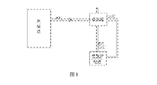
- FIG. 1 is a schematic structural diagram of a waste pit odor treatment system in the prior art.
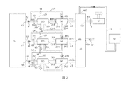
- FIG. 2 is a schematic structural diagram of the first embodiment of the low-nitrogen coupling combustion treatment system for waste pit odor and solid waste according to the present invention.
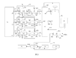
- FIG. 3 is a schematic structural diagram of the second embodiment of the waste pit odor and solid waste low-nitrogen coupled combustion treatment system of the present invention.
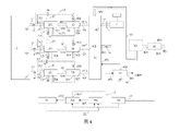
- FIG. 4 is a schematic structural diagram of the third embodiment of the low-nitrogen coupling combustion treatment system for waste pit odor and solid waste according to the present invention.
- the low-nitrogen coupling combustion treatment system for waste pit odor and solid waste provided by the present invention includes a waste pit 10 , three odor incineration mechanisms 20 , and three heat exchangers 30 , a hot air duct 40 and a waste incinerator 50 .
- the garbage pit 10 is provided with an odor outlet 101, and the odor incineration mechanism 20 includes: an incineration chamber 200 for burning odor, an odor inlet 201 communicating with the incineration chamber 200, a fuel inlet 202, and a combustion odor outlet 203 .
- the odor outlet 101 of the garbage pit 10 is connected to the odor inlet 201 of the odor incineration mechanism 20 through the odor conveying pipe L1, and the odor conveying pipe L1 is provided with an exhaust fan P, so as to realize the odor in the garbage pit 10. The effect of being pumped into the odor incineration mechanism 20 for combustion.
- the fuel inlet 202 of the odor incineration mechanism 20 is connected to the fuel source S through the fuel delivery pipeline L2.
- the fuel source S is natural gas, which has the advantages of high calorific value and low pollution. After the fuel is mixed with the heated odor, it is burned at a high temperature in the incineration chamber 200, and the odor is effectively incinerated, so that it no longer pollutes the environment, and can generate heat for use.
- the combustion odor outlet 203 of the odor incineration mechanism 20 is connected to the hot air duct 40 through the flue gas discharge pipe L3, so as to discharge the high temperature and low oxygen waste gas produced by the mixed combustion of fuel and odor into the hot air duct.
- the hot air duct 40 is provided with an air inlet 400 , a first air outlet 401 and a second air outlet 402 . As shown in FIG. 2 , the air inlet 400 is connected to the combustion odor outlet 203 of the odor incineration mechanism 20 .
- the first exhaust port 401 is connected to the chimney Y through the first exhaust duct S1, and the first exhaust duct S1 is provided with a valve F, so that when the waste incinerator 50 does not need combustion-supporting air, the flue gas can be removed. Direct emission through chimney Y.
- the hot air pipe 40 is connected with the combustion-supporting air inlet (not marked in the figure) of the waste incinerator 50 through the second exhaust air duct S2, and the high-temperature and low-oxygen flue gas discharged by the odor incineration mechanism 20 is cited as the combustion-supporting air of the waste incinerator 50,
- the waste incineration can be carried out in a high temperature (not exceeding the upper limit temperature of the waste incinerator) and low oxygen environment, which can effectively reduce the production of nitrogen oxides and carbon monoxide, thereby greatly preventing the coking phenomenon of the waste incinerator and improving the combustion efficiency. , and prolong the life of the furnace body.
- the hot air duct 40 is also provided with a conditioning air inlet 403, and a conditioning fan TP is connected to the conditioning air inlet 403, which is used to introduce air and adjust the temperature and oxygen content of the flue gas, so that the temperature of the flue gas is controlled at about 220°C, and the oxygen content is controlled. Controlled at about 15-18%, which can effectively reduce the generation of nitrogen oxides in waste incinerators and prevent coking at the same time.
- a first heat exchanger 30 is provided between the odor incineration mechanism 20 and the hot air pipe 40, and the first heat exchanger 30 is provided with a high temperature gas inlet 301, a medium temperature
- the gas outlet 302 , the odor inlet 303 , and the odor outlet 304 , and the odor incineration mechanism 20 is further provided with an odor branch inlet 204 .
- the high temperature gas inlet 301 of the first heat exchanger 30 is connected to the combustion odor outlet 203 of the odor incineration mechanism 20, the medium temperature gas outlet 302 is connected to the air inlet 400 of the hot air pipe 40, and the odor inlet 303 is connected to the garbage pit.
- the odor outlet 101 of 10 is connected through the odor branch pipe L4, and the odor outlet 304 is connected with the odor branch inlet 204 of the odor incineration mechanism 20 through the pipe, so that the odor in the garbage pit 10 is led out to
- the waste flue gas with a temperature of up to 800°C generated by the odor incineration mechanism 20 is heated into hot air with a temperature of 500°C or higher, and then introduced into the incineration chamber 200, where it is mixed and burned with the fuel, and the odor is reduced. After the gas is heated and then burned, it can not only save energy, but also improve the combustion efficiency of the odor incineration mechanism 20, reduce the external fuel consumption of the odor incineration mechanism 20, and achieve the purpose of recycling most of the waste heat of the exhaust gas.
- valve V1 is provided on the odor transmission pipeline L1
- valve V4 is provided on the odor branch pipeline L4.
- two or more odor incineration mechanisms 20 are provided, and they are used in a switch mode. When one of the odor incineration mechanisms is damaged or needs maintenance, the other odor incineration mechanism can be switched to operate. , so that uninterrupted treatment of odor can be achieved to reduce the risk of pollution and leakage.
- odor incineration mechanisms 20 there are three odor incineration mechanisms 20, and a heat exchanger 30 is provided between each odor incineration mechanism 20 and the hot air pipe 40, and the garbage pit 10 is provided with three odor outlets 101, all of which are provided with branches.
- the pipelines L4 are respectively connected to the three heat exchangers 30 , and the odor outlet 304 of each heat exchanger 30 is connected to the fuel inlet 202 of the corresponding odor incineration mechanism 20 through a pipeline. Therefore, when the whole system is running, two of the odor incineration mechanisms 20 can be in operation, and the other one is in standby, so as to ensure the complete treatment of odor, minimize pollution, and provide sufficient low-oxygen and high-temperature waste gas , used for combustion in waste incinerators.
- a second heat exchanger 60 is further included.
- the second heat exchanger 60 includes: a cold air inlet 601 , a hot air outlet 602 , a hot steam inlet 603 , and a condensation Water outlet 604.
- the hot air duct 40 is provided with an air inlet 404, the air inlet 404 is connected with the hot air outlet 602 of the second heat exchanger 60, and the hot steam inlet 603 of the second heat exchanger 60 is connected with the steam turbine steam discharge system 70, thereby utilizing
- the waste heat of the steam discharged from the gas separation tank 703 in the steam turbine steam discharge system 70 is used to preheat the air, and the hot air then enters the hot air pipe 40 to be mixed with the high temperature and low oxygen flue gas (exhaust gas), so that the gas separation tank 703 can be effectively recovered.
- the waste heat of the exhausted steam is further recovered and utilized for energy.
- the steam turbine steam discharge system 70 includes a steam turbine 701 , a deaerator 702 and a gas separation tank 703 connected in sequence, and the gas outlet 7031 of the gas separation tank 703 is connected to the hot steam inlet 603 of the second heat exchanger 60 .
- the steam of the steam turbine 701 enters the gas separation tank 703 after passing through the deaerator 702, so that the waste heat discharged from the steam turbine steam discharge system can be effectively recovered and utilized, and energy can be effectively saved.
- the discharge port of the steam turbine can be directly connected to the sub-tank to save the oxygen removal step.
- a first on-off valve may be provided on the pipeline connecting the gas distributor 703 and the steam turbine 701 adjacent to the gas distributor 703, and the pipeline connecting the deaerator 702 with the steam turbine 701 is adjacent to the deaerator 701.
- a second switch valve (not shown) can be set at the oxygen deaerator 702. When the deaerator 702 is required to work, the second switch valve is opened and the first switch valve is closed at the same time. When the deaerator 702 is not required to work, the first switch valve is opened. The on-off valve closes the second on-off valve at the same time.
- the gas distribution tank 703 can be provided with a branch outlet 7032, and the branch outlet 7032 is connected with the inlet (not shown in the figure) of the absorption refrigeration system 90, so that part of the heat is used for refrigeration, and the Air-conditioning is used for production workshops and office areas.
- the outlet (not marked in the figure) of the absorption refrigeration system 90 is connected to the inlet of the deaerator 702 (not marked in the figure) through the condensed water pipeline Z2, so that the high-temperature condensed water formed after refrigeration is returned to the condensed water pipeline Z2. into deaerator 702.
- the system further includes a third heat exchanger 80 , and the third heat exchanger 80 includes: a hot flue gas inlet 801 , a cold flue gas outlet 802 , a cold water inlet 803 and
- the steam outlet 804 and the hot flue gas inlet 801 are connected to the flue gas outlet (not numbered) of the waste incinerator 50, the cold flue gas outlet 802 is connected to the chimney (not shown), and the cold water inlet 803 is connected to a cold water source (not shown).
- the steam outlet 804 is provided with a steam pipe Z1
- the steam pipe Z1 is connected with the steam inlet (not numbered) of the steam turbine 701 of the steam turbine steam discharge system 70, so that the steam produced by the incineration of the waste incinerator 50 can be input.
- the steam turbine generates electricity, and the third heat exchanger 80 can be used to adjust the steam temperature and pressure of the steam turbine.
Landscapes
- Engineering & Computer Science (AREA)
- Mechanical Engineering (AREA)
- General Engineering & Computer Science (AREA)
- Environmental & Geological Engineering (AREA)
- Chemical & Material Sciences (AREA)
- Combustion & Propulsion (AREA)
- Physics & Mathematics (AREA)
- Thermal Sciences (AREA)
Abstract
一种垃圾坑臭气与固体垃圾低氮耦合燃烧处理系统,其包括:垃圾坑(10)、至少一个臭气焚烧机构(20)和垃圾焚烧炉(50),其中,垃圾坑(10)设有臭气出口(101),臭气焚烧机构(20)包括:用于燃烧废气的焚烧室(200)、与焚烧室(200)相连通的臭气进口(201)、燃料进口(202)以及燃烧臭气出口(203),臭气进口(201)通过臭气输送管道(L1)与垃圾坑(10)的臭气出口(101)相连接,燃料进口(202)通过燃料输送管道(L2)与燃料源(S)相连接,燃烧臭气出口(203)通过烟气排放管道(L3)与垃圾焚烧炉(50)的助燃空气入口相连接,以引用臭气焚烧机构(20)排放的高温低氧烟气作为垃圾焚烧炉(50)的助燃空气,使得垃圾焚烧在高温低氧环境下进行,可以有效减少氮氧化物的产生,从而可以极大程度地防止垃圾焚烧炉(50)产生结焦现象,提高燃烧效率,并且延长使用寿命。
Description
本发明涉及垃圾处理领域,具体为一种可以处理臭气同时防止垃圾焚烧结焦且节能的垃圾坑臭气与固体垃圾低氮耦合燃烧处理系统。
随着人口数量持续增加、城市化进程加快和生活水平的提高,近年来,城市垃圾数量迅猛增加。我国城市垃圾无害化处置主要有三种方式:填埋、焚烧和堆肥。我国生活垃圾处理主要是以填埋为主,焚烧和堆肥的比例较少,但是焚烧的比例每年都在增长。焚烧相比填埋具有减容、减量、以及能源再次利用等优点。如果继续以填埋为主,在不久的将来,更多城市将被垃圾所包围,这就迫使我国加快垃圾焚烧厂的建设速度。
城市生活垃圾焚烧厂的垃圾在焚烧前将进行一定量的堆放储存和干化过程,因此会产生一定量的垃圾渗滤液。垃圾渗滤液是一种成分复杂的高浓度有机废水,被公认为当今世界上最难处理达标的污水之一。垃圾渗滤液的典型特点为BOD和COD浓度高、重金属浓度高、水质水量变化大、氨氮的含量高、微生物营养比例失调,其不仅极为恶臭难闻,而且相关指标为一般城市污水的10-100倍。如果生活垃圾渗滤液直接排放环境中,则会对周围土壤和水体造成严重污染,垃圾渗滤液所到之处,植物无法生长。
城市生活垃圾在焚烧过程中,在尾气净化设备中会沉降高含量二噁英和重金属的飞灰。根据《生活垃圾填埋污染控制标准GB168892008》中明确规定生活垃圾焚烧飞灰属于危险废弃物,同时填埋要求为生活垃圾焚烧飞灰含水率效率小于30%,二噁英含量低于3ug TEQ/Kg和重金属的浸出毒性低于相应的标准值。特别是,二噁英(PCDD/Fs)是多氯代二苯并二噁英(PCDDs)和多氯代二苯并呋喃(PCDFs)的统称。公认为“世界上最毒的物质”,最大危害是具有不可逆 的“三致”毒性,即致畸、致癌、致突变;一旦进入在生物体内,在生物体脂肪层和脏器堆积而几乎不能排出或降解,产生积累性中毒,严重影响周围的生态环境。
另外,存储垃圾的垃圾坑在有机废弃物发酵过程中,产生大量的有机废气,其恶臭无比,严重污染周边环境。现有垃圾坑有机废气的处理方式如图1所示,垃圾坑废气温度在20℃,被抽吸通过换热器加热到220℃左右导入垃圾焚烧炉燃烧,燃料焚烧炉产生的300℃的蒸汽用于换热器的热源。这样的处理模式存在比较严重的缺陷,废气容易泄露,污染周边环境,影响周边居民生活;另外有机废气焚烧处理过程中,需要耗费能源,无法节约成本;垃圾焚烧炉在相对较低的温度下燃烧垃圾,产生灰分多,炉壁容易产生结焦现象,影响垃圾焚烧炉使用寿命和焚烧效率。
发明内容
本发明的目的在于克服以上现有技术存在的不足,提供一种可以有效去除垃圾坑臭气污染同时减少垃圾焚烧炉结焦现象,又具有节能并易于实现的垃圾坑臭气与固体垃圾低氮耦合燃烧处理系统。
为达到上述目的,本发明提供了一种垃圾坑臭气与固体垃圾低氮耦合燃烧处理系统,其包括:垃圾坑、至少一个臭气焚烧机构和垃圾焚烧炉,其中,垃圾坑设有臭气出口,臭气焚烧机构包括:用于燃烧废气的焚烧室、与焚烧室相连通的臭气进口、燃料进口以及燃烧臭气出口,臭气进口通过臭气输送管道与垃圾坑的臭气出口相连接,燃料进口通过燃料输送管道与燃料源相连接,燃烧臭气出口通过烟气排放管道与垃圾焚烧炉的助燃空气入口相连接,以引用臭气焚烧机构排放的高温低氧烟气作为垃圾焚烧炉的助燃空气。
可选择地,臭气焚烧机构与垃圾焚烧炉之间设有热风管,热风管设有进风口、第一排风口及第二排风口,其中,进风口与臭气焚烧机构相连接;第一排风口通过第一排风管道与烟囱相连接,第一排风管道上设有阀门;第二排风口通过第二排风管道与垃圾焚烧炉的助燃空气入口相连接以引用臭气焚烧机构排放的高温低氧烟气作为垃圾焚烧炉的助燃空气。
可选择地,热风管设有调节空气入口,调节空气入口处连接有风机,用于引入空气,调节烟气温度和含氧量,使得烟气温度控制在220℃左右,含氧量控制在15-18%左右,可以有效地减少垃圾焚烧炉氮氧化物产生,防止结焦。
可选择地,臭气焚烧机构与热风管之间设有第一换热器,第一换热器设有高温气体入口、中温气体出口、臭气进入口、以及臭气排出口,臭气焚烧机构还设有臭气分支进口;高温气体入口与臭气焚烧机构的燃烧臭气出口相连接,中温气体出口与热风管的进风口相连接,臭气进入口与垃圾坑的臭气出口通过臭气分支管道相连接,第一换热器的臭气排出口通过管道与臭气焚烧机构的臭气分支进口相连接,由此,第一换热器将垃圾坑中的部分臭气引出,在第一换热器中,通过臭气焚烧机构产生的高达800℃的烟气,被加热成温度高达500℃以上的热臭气后,导入臭气焚烧机构与燃料一起混合燃烧。
优选地,臭气输送管道上设有主阀门,臭气分支管道上设有辅阀门。在装置刚开始运行时,打开主阀门,关闭辅阀门,待系统运行一段时间后,则关闭主阀门,打开辅阀门。若臭气分支管道出现问题需要检修时,再关闭辅阀门,打开主阀门,此时臭气不加热直接燃烧,虽然会浪费部分能量,但是装置不用停机仍可正常运作。
可选择地,垃圾坑臭气与固体垃圾低氮耦合燃烧处理系统设有至少两个臭气焚烧机构,使用的时候进行切换式使用,可以在其中一个臭气焚烧机构损坏或者需要保修的时候,切换另一个臭气焚烧机构运行,这样可以做到不间断的对废气进行处理,减少污染和危险。
可选择地,垃圾坑臭气与固体垃圾低氮耦合燃烧处理系统设有三个臭气焚烧机构,运行时,其中两个臭气焚烧机构在运行,另外一个臭气焚烧机构在备用。
可选择地,还包括第二换热器,第二换热器包括:冷空气入口、热空气出口、热蒸汽入口、以及冷凝水出口;热风管还设有空气入口,空气入口与第二换热器的热空气出口相连接,第二换热器的热蒸汽入口与汽轮机蒸汽排放系统连接,由此,第二换热器利用汽轮机蒸汽排放系统中的汽轮机的蒸汽排放余热来预热空气,然后热空气再进入到热风管中与烟气进行混合。
可选择地,汽轮机蒸汽排放系统包括依次连接的汽轮机、除氧器、以及分气罐,分气罐的出气口与第二换热器的热蒸汽入口相连接。
可选择地,分气罐还可以设置分支出口,分支出口与吸收式制冷系统的入口相连接,从而将部分热量用于制冷,制成的冷气供生产车间办公区使用;吸收式制冷系统的出口处通过冷凝水管道与除氧器的入口相连接,使得制冷后形成的高温冷凝水经冷凝水管道再回到除氧器中。
可选择地,还包括第三换热器,第三换热器包括:热烟气入口、冷烟气出口、冷水入口以及蒸汽出口、热烟气入口与垃圾焚烧炉的蒸汽出口相连接,冷烟气出口与烟囱相连接,冷水入口与冷水源相连接,蒸汽出口处设有蒸汽管道,蒸汽出口通过蒸汽管道与汽轮机蒸汽排放系统的汽轮器的进气口相连接。
与现有技术相比,本发明的优点和有益效果包括:(1)、减少污染:可以对垃圾坑废气进行完全处理,避免泄露污染环境;(2)、节约能源:充分的进行余热回收利用,有效的节约能源消耗;(3)、运行成本低:回收利用排放余热,且系统改造和运行管理简便,成本低;(4)、引用臭气焚烧机构排放的高温低氧烟气作为垃圾焚烧炉的助燃空气,使得垃圾焚烧在高温低氧环境下进行,可以有效减少氮氧化物的产生,从而可以极大程度地防止垃圾焚烧炉产生结焦现象,提高燃烧效率,并且延长使用寿命。
图1为现有技术的垃圾坑臭气处理系统结构示意图。
图2为本发明的垃圾坑臭气与固体垃圾低氮耦合燃烧处理系统的第一种实施方式的结构示意图。
图3为本发明的垃圾坑臭气与固体垃圾低氮耦合燃烧处理系统的第二种实施方式的结构示意图。
图4为本发明的垃圾坑臭气与固体垃圾低氮耦合燃烧处理系统的第三种实施方式的结构示意图。
以下结合附图和具体实施例对本发明做详细的描述。附图显示出了本发明之较佳实施例的具体结构。其中各元件的结构特点,而如果有描述到方向(上、下、左、右、前及后)时,是以图1所示的结构为参考描述,但本发明的实际使用方向并不局限于此。
请参考图2,作为一种非限制性实施方式,本发明提供的垃圾坑臭气与固体垃圾低氮耦合燃烧处理系统包括垃圾坑10、三个臭气焚烧机构20、三个换热器30、热风管40和垃圾焚烧炉50。
垃圾坑10上设有臭气出口101,臭气焚烧机构20包括:用于燃烧臭气的焚烧室200、与焚烧室200相连通的臭气进口201、燃料进口202、以及燃烧臭气出口203。
垃圾坑10的臭气出口101通过臭气输送管道L1与臭气焚烧机构20的臭气进口201相连接,臭气输送管道L1上设有抽风机P,从而实现将垃圾坑10内的臭气抽至臭气焚烧机构20内进行燃烧的效果。
臭气焚烧机构20的燃料进口202通过燃料输送管道L2与燃料源S相连接。燃料源S为天然气,具有高热值且低污染优点。燃料与加热后的臭气混合后在焚烧室200内高温燃烧,对臭气进行有效的焚烧处理,使其不再污染环境,且能产生热量供利用。
臭气焚烧机构20的燃烧臭气出口203通过烟气排放管道L3与热风管40相连接,从而将燃料与臭气混合燃烧产生的高温低氧废气排放到热风管中。热风管40设有进风口400、第一排风口401及第二排风口402。如图2所示,进风口400与臭气焚烧机构20的燃烧臭气出口203相连接。第一排风口401通过第一排风管道S1与烟囱Y相连接,第一排风管道S1上设有阀门F,由此在垃圾焚烧炉50不需要助燃空气的情况下,可以将烟气通过烟囱Y直接排放。
热风管40通过第二排风管道S2与垃圾焚烧炉50的助燃空气入口(图中未标示)连接,引用臭气焚烧机构20排放的高温低氧烟气作为垃圾焚烧炉50的助燃空气,可以使垃圾焚烧在高温(不超过垃圾焚烧炉极限上限温度)低氧环境下进行,可以有效减少氮氧化物以及一氧化碳的产生,从而可以极大程度的防止垃圾焚烧炉产生结焦现象,提高燃 烧效率,且延长炉体寿命。
热风管40还设有调节空气入口403,调节空气入口403处连接有调节风机TP,用于引入空气,调节烟气温度和含氧量,使烟气温度控制在220℃左右,含氧量控制在15-18%左右,从而可以有效的减少垃圾焚烧炉氮氧化物产生,同时防止结焦。
在该非限制性实施方式中,如图2所示,臭气焚烧机构20与热风管40之间设有第一换热器30,第一换热器30设有高温气体入口301、中温气体出口302、臭气进入口303、以及臭气排出口304,臭气焚烧机构20还设有臭气分支进口204。
第一换热器30的高温气体入口301与臭气焚烧机构20的燃烧臭气出口203相连接,中温气体出口302与热风管40的进风口400相连接,臭气进入口303与垃圾坑10的臭气出口101通过臭气分支管道L4相连接,臭气排出口304通过管道与臭气焚烧机构20的臭气分支进口204相连接,由此,垃圾坑10中的臭气被引出至第一换热器30中,利用臭气焚烧机构20产生的高达800℃的废烟气,被加热成温度为500℃以上的热风后,再导入焚烧室200中,与燃料一起混合燃烧,臭气经过加热后再燃烧,不仅可以节能,还可以提高臭气焚烧机构20的燃烧效率,减少臭气焚烧机构20的外源燃料消耗量,达到回收利用绝大部分废气余热的目的。
由此,臭气输送管道L1上设有阀门V1,臭气分支管道L4上设有阀门V4,在系统刚开始运行时,打开阀门V1,关闭阀门V4,待系统运行一段时间后,则关闭阀门V1,打开阀门V4。若臭气分支管道L4出现问题需要检修时,再关闭阀门V4,打开阀门V1,此时臭气不加热直接燃烧,虽然会浪费部分能量,但是系统不用停机仍可正常运作。
在该非限制性实施方式中,臭气焚烧机构20设置两个以上,使用的时候进行切换式使用,可以在其中一个臭气焚烧机构损坏或者需要保修的时候,切换另一个臭气焚烧机构运行,这样可以做到不间断的对臭气进行处理,减少污染和外泄危险。
在本发明中,臭气焚烧机构20设置有3个,每一个臭气焚烧机构20与热风管40之间设置换热器30,垃圾坑10设有三个臭气出口101,均通过设置分支管路L4分别与三个换热器30相连接,每个换热器30 的臭气出口304均通过管道与对应的臭气焚烧机构20的燃料进口202相连接。由此,整个系统在运行时,可使得其中两个臭气焚烧机构20在运行,另外一个在备用,这样可以保证将臭气处理彻底,最低限度减少污染,且可以提供充足的低氧高温废气,用于垃圾焚烧炉助燃。
作为另一种非限制性实施方式,如图3所示,还包括第二换热器60,第二换热器60包括:冷空气入口601、热空气出口602、热蒸汽入口603、以及冷凝水出口604。热风管40设有空气入口404,空气入口404与第二换热器60的热空气出口602相连接,第二换热器60的热蒸汽入口603与汽轮机蒸汽排放系统70相连接,从而利用汽轮机蒸汽排放系统70中的分气罐703排放的蒸汽余热来预热空气,热空气然后进入到热风管40中与高温低氧烟气(废气)进行混合,这样可以有效回收分气罐703排放的蒸汽余热,进一步回收利用能源。
如图3所示,汽轮机蒸汽排放系统70包括依次连接的汽轮机701、除氧器702以及分气罐703,分气罐703的出气口7031与第二换热器60的热蒸汽入口603相连接。由此,汽轮机701的蒸汽通过除氧器702后进入分气罐703,从而可以有效地回收利用汽轮机蒸汽排放系统排放余热,有效地节约能源。作为一种简化,汽轮机的排放口可以直接与分气罐连接,省去除氧步骤。作为一种非限制实施方式,分气罐703与汽轮机701相连的管线上邻近分气罐703处可设置第一开关阀门(图未示),除氧器702与汽轮机701相连的管线上邻近除氧器702处可设置第二开关阀门(图未示),当需要除氧器702工作时,打开第二开关阀门同时关闭第一开关阀门,当不需要除氧器702工作时,打开第一开关阀门同时关闭第二开关阀门。
在该非限制性实施方式中,分气罐703可以设置分支出口7032,分支出口7032与吸收式制冷系统90的入口(图中未标示)相连接,从而将部分热量用于制冷,制成的冷气供生产车间、办公区使用。吸收式制冷系统90的出口(图中未标示)处通过冷凝水管道Z2与除氧器702的入口(图中未标示)相连接,使得制冷后形成的高温冷凝水经冷凝水管道Z2再回到除氧器702中。
作为又一种非限制性实施方式,如图4所示,系统还包括第三换热器80,第三换热器80包括:热烟气入口801、冷烟气出口802、冷水入口803以及蒸汽出口804、热烟气入口801与垃圾焚烧炉50的烟气出口 (未标号)相连接,冷烟气出口802与烟囱(图未示)相连接,冷水入口803与冷水源(图未示)相连接,蒸汽出口804处设有蒸汽管道Z1,蒸汽管道Z1与汽轮机蒸汽排放系统70的汽轮机701的蒸汽入口(未标号)连接,从而可以将垃圾焚烧炉50焚烧的热量制成的蒸汽输入汽轮机进行发电,第三换热器80便可用于调节汽轮机的蒸汽温度和压力。
以上仅为本发明的较佳实施例,当不能以此限定本发明实施的范围,即依本发明申请专利范围及发明说明内容所作的简单等效变化与修饰,皆仍属本发明专利涵盖的范围。
Claims (10)
- 一种垃圾坑臭气与固体垃圾低氮耦合燃烧处理系统,包括:垃圾坑、至少一个臭气焚烧机构以及垃圾焚烧炉,其特征在于,所述垃圾坑设有臭气出口,所述臭气焚烧机构包括:用于燃烧臭气的焚烧室、与所述焚烧室相连通的臭气进口、燃料进口以及燃烧臭气出口,所述臭气进口通过臭气输送管道与所述垃圾坑的臭气出口相连接,所述燃料进口通过燃料输送管道与燃料源相连接,所述燃烧臭气出口通过烟气排放管道与所述垃圾焚烧炉的助燃空气入口相连接。
- 根据权利要求1所述的垃圾坑臭气与固体垃圾低氮耦合燃烧处理系统,其特征在于,所述臭气焚烧机构与所述垃圾焚烧炉之间设有热风管,所述热风管设有进风口、第一排风口及第二排风口,其中,所述进风口与所述臭气焚烧机构相连接;所述第一排风口通过第一排风管道与烟囱相连接,所述第一排风管道上设有阀门;所述第二排风口通过第二排风管道与所述垃圾焚烧炉的助燃空气入口相连接以引用所述臭气焚烧机构排放的高温低氧烟气作为所述垃圾焚烧炉的助燃空气。
- 根据权利要求2所述的垃圾坑臭气与固体垃圾低氮耦合燃烧处理系统,其特征在于,所述热风管还设有调节空气入口,所述调节空气入口处连接有风机。
- 根据权利要求3所述的垃圾坑臭气与固体垃圾低氮耦合燃烧处理系统,其特征在于,所述臭气焚烧机构与所述热风管之间设有第一换热器,所述第一换热器设有高温气体入口、中温气体出口、臭气进入口、以及臭气排出口,所述臭气焚烧机构还设有臭气分支进口;所述高温气体入口与所述臭气焚烧机构的燃烧臭气出口相连接,所述中温气体出口与所述热风管的进风口相连接,所述臭气进入口与所述垃圾坑的臭气出口通过臭气分支管道相连接,所述第一换热器的臭气排出口通过管道与所述臭气焚烧机构的臭气分支进口相连接。
- 根据权利要求4所述的垃圾坑臭气与固体垃圾低氮耦合燃烧处理系统,其特征在于,所述垃圾坑臭气与固体垃圾低氮耦合燃烧处理系统设有至少两个所述臭气焚烧机构。
- 根据权利要求5所述的垃圾坑臭气与固体垃圾低氮耦合燃烧处理系统,其特征在于,所述垃圾坑臭气与固体垃圾低氮耦合燃烧处理系统设有三个所述臭气焚烧机构。
- 根据权利要求2所述的垃圾坑臭气与固体垃圾低氮耦合燃烧处理系统,其特征在于,还包括第二换热器,所述第二换热器包括:冷空气入口、热空气出口、热蒸汽入口、以及冷凝水出口;所述热风管还设有空气入口,所述空气入口与所述第二换热器的热空气出口相连接,所述第二换热器的热蒸汽入口与汽轮机蒸汽排放系统连接。
- 根据权利要求7所述的垃圾坑臭气与固体垃圾低氮耦合燃烧处理系统,其特征在于,所述汽轮机蒸汽排放系统包括依次连接的汽轮机、除氧器、以及分气罐,所述分气罐的出气口与所述第二换热器的热蒸汽入口相连接。
- 根据权利要求8所述的垃圾坑臭气与固体垃圾低氮耦合燃烧处理系统,其特征在于,所述分气罐还设有分支出口,所述分支出口与吸收式制冷系统的入口相连接;所述吸收式制冷系统的出口处通过冷凝水管道与所述除氧器的入口相连接。
- 根据权利要求9所述的垃圾坑臭气与固体垃圾低氮耦合燃烧处理系统,其特征在于,还包括第三换热器,所述第三换热器包括:热烟气入口、冷烟气出口、冷水入口以及蒸汽出口、所述热烟气入口与所述垃圾焚烧炉的蒸汽出口相连接,所述冷烟气出口与烟囱相连接,所述冷水入口与冷水源相连接,所述蒸汽出口处设有蒸汽管道,所述蒸汽出口通过蒸汽管道与所述汽轮机蒸汽排放系统的所述汽轮器的进气口相连接。
Priority Applications (1)
| Application Number | Priority Date | Filing Date | Title |
|---|---|---|---|
| US17/525,945 US12050009B2 (en) | 2020-11-09 | 2021-11-14 | Low nitrogen coupling combustion system for the disposal of waste stink gas and solid waste |
Applications Claiming Priority (2)
| Application Number | Priority Date | Filing Date | Title |
|---|---|---|---|
| CN202011241960.9 | 2020-11-09 | ||
| CN202011241960.9A CN112413594B (zh) | 2020-11-09 | 2020-11-09 | 垃圾坑臭气与固体垃圾低氮耦合燃烧处理系统 |
Related Child Applications (1)
| Application Number | Title | Priority Date | Filing Date |
|---|---|---|---|
| US17/525,945 Continuation US12050009B2 (en) | 2020-11-09 | 2021-11-14 | Low nitrogen coupling combustion system for the disposal of waste stink gas and solid waste |
Publications (1)
| Publication Number | Publication Date |
|---|---|
| WO2022095154A1 true WO2022095154A1 (zh) | 2022-05-12 |
Family
ID=74780975
Family Applications (1)
| Application Number | Title | Priority Date | Filing Date |
|---|---|---|---|
| PCT/CN2020/131583 Ceased WO2022095154A1 (zh) | 2020-11-09 | 2020-12-29 | 垃圾坑臭气与固体垃圾低氮耦合燃烧处理系统 |
Country Status (2)
| Country | Link |
|---|---|
| CN (1) | CN112413594B (zh) |
| WO (1) | WO2022095154A1 (zh) |
Cited By (1)
| Publication number | Priority date | Publication date | Assignee | Title |
|---|---|---|---|---|
| CN115681993A (zh) * | 2022-11-12 | 2023-02-03 | 江苏大鸿环保设备有限公司 | 一种危废垃圾焚烧炉的高温助燃配风系统及其使用方法 |
Citations (8)
| Publication number | Priority date | Publication date | Assignee | Title |
|---|---|---|---|---|
| JPH09236220A (ja) * | 1995-12-28 | 1997-09-09 | Ebara Corp | 固形廃棄物のガス化燃焼方法 |
| JP2000249324A (ja) * | 1999-02-25 | 2000-09-12 | Hitachi Zosen Corp | ごみ処理設備における脱臭方法 |
| CN101539296A (zh) * | 2009-04-13 | 2009-09-23 | 南京大学 | 基于垃圾填埋气为辅助燃料的城市污泥焚烧系统 |
| CN201396766Y (zh) * | 2009-05-31 | 2010-02-03 | 王中 | 一种垃圾焚烧炉烟气再循环低位废热能再利用装置 |
| CN105387472A (zh) * | 2015-12-04 | 2016-03-09 | 赛鼎工程有限公司 | 一种煤化工多种恶臭气体联合处理工艺 |
| CN206924608U (zh) * | 2017-03-15 | 2018-01-26 | 光大环保能源(苏州)有限公司 | 用于垃圾渗滤液处理站的臭气处理系统 |
| CN206944178U (zh) * | 2017-07-11 | 2018-01-30 | 光大环保技术研究院(南京)有限公司 | 一种烟气处理系统 |
| CN109695888A (zh) * | 2018-08-20 | 2019-04-30 | 中电华创电力技术研究有限公司 | 一种垃圾焚烧炉资源综合利用装置 |
Family Cites Families (8)
| Publication number | Priority date | Publication date | Assignee | Title |
|---|---|---|---|---|
| DE3512810A1 (de) * | 1985-04-10 | 1986-10-23 | Dyckerhoff Engineering GmbH, 6200 Wiesbaden | Verfahren und anlage zur verbrennung von abfallstoffen |
| JP2003166707A (ja) * | 2001-11-30 | 2003-06-13 | Mitsubishi Heavy Ind Ltd | 廃棄物焼却炉及びその燃焼方法 |
| CN102192512B (zh) * | 2010-03-02 | 2013-07-31 | 王振坤 | 垃圾焚烧炉 |
| CN104359111B (zh) * | 2014-11-28 | 2016-09-14 | 合肥工业大学 | 一种生活垃圾干燥焚烧装置 |
| CN108679614A (zh) * | 2018-06-14 | 2018-10-19 | 南京凯盛开能环保能源有限公司 | 一种水泥窑协同处置生活垃圾发电系统及方法 |
| KR101997197B1 (ko) * | 2019-03-18 | 2019-07-08 | 주식회사 동양보일러 | 자원화 시설용 컴팩트 타입 고농도 악취 제거 시스템 |
| CN111609404A (zh) * | 2020-07-01 | 2020-09-01 | 大唐环境产业集团股份有限公司 | 一种用于低热值垃圾焚烧炉的烟气净化与余热利用系统 |
| CN215765102U (zh) * | 2020-11-09 | 2022-02-08 | 广东工业大学 | 使用垃圾坑臭气助燃的固体垃圾节能低氮燃烧系统 |
-
2020
- 2020-11-09 CN CN202011241960.9A patent/CN112413594B/zh active Active
- 2020-12-29 WO PCT/CN2020/131583 patent/WO2022095154A1/zh not_active Ceased
Patent Citations (8)
| Publication number | Priority date | Publication date | Assignee | Title |
|---|---|---|---|---|
| JPH09236220A (ja) * | 1995-12-28 | 1997-09-09 | Ebara Corp | 固形廃棄物のガス化燃焼方法 |
| JP2000249324A (ja) * | 1999-02-25 | 2000-09-12 | Hitachi Zosen Corp | ごみ処理設備における脱臭方法 |
| CN101539296A (zh) * | 2009-04-13 | 2009-09-23 | 南京大学 | 基于垃圾填埋气为辅助燃料的城市污泥焚烧系统 |
| CN201396766Y (zh) * | 2009-05-31 | 2010-02-03 | 王中 | 一种垃圾焚烧炉烟气再循环低位废热能再利用装置 |
| CN105387472A (zh) * | 2015-12-04 | 2016-03-09 | 赛鼎工程有限公司 | 一种煤化工多种恶臭气体联合处理工艺 |
| CN206924608U (zh) * | 2017-03-15 | 2018-01-26 | 光大环保能源(苏州)有限公司 | 用于垃圾渗滤液处理站的臭气处理系统 |
| CN206944178U (zh) * | 2017-07-11 | 2018-01-30 | 光大环保技术研究院(南京)有限公司 | 一种烟气处理系统 |
| CN109695888A (zh) * | 2018-08-20 | 2019-04-30 | 中电华创电力技术研究有限公司 | 一种垃圾焚烧炉资源综合利用装置 |
Cited By (2)
| Publication number | Priority date | Publication date | Assignee | Title |
|---|---|---|---|---|
| CN115681993A (zh) * | 2022-11-12 | 2023-02-03 | 江苏大鸿环保设备有限公司 | 一种危废垃圾焚烧炉的高温助燃配风系统及其使用方法 |
| CN115681993B (zh) * | 2022-11-12 | 2023-08-04 | 江苏大鸿环保设备有限公司 | 一种危废垃圾焚烧炉的高温助燃配风系统及其使用方法 |
Also Published As
| Publication number | Publication date |
|---|---|
| CN112413594A (zh) | 2021-02-26 |
| CN112413594B (zh) | 2025-10-10 |
Similar Documents
| Publication | Publication Date | Title |
|---|---|---|
| CN102219346B (zh) | 一种利用余热产生高温循环空气的污泥烘干及处理系统 | |
| CN203869049U (zh) | 危险废物焚烧系统 | |
| CN107572740A (zh) | 一种利用烟气余热的污泥低温干化焚烧一体化方法及系统 | |
| CN102012032A (zh) | 一种医疗垃圾成套焚烧装置 | |
| CN204629501U (zh) | 一种零排放、能量自耗型垃圾完全裂解处理系统 | |
| CN101476729A (zh) | 城市生活垃圾干燥预处理方法及装置 | |
| CN206207423U (zh) | 一种磁化垃圾热解站 | |
| WO2022193537A1 (zh) | 封闭式负压固体废物控氧热解装置 | |
| CN108413411A (zh) | 生活垃圾焚烧发电协同污泥干化处理方法和系统 | |
| CN112413594B (zh) | 垃圾坑臭气与固体垃圾低氮耦合燃烧处理系统 | |
| US12050009B2 (en) | Low nitrogen coupling combustion system for the disposal of waste stink gas and solid waste | |
| CN215765102U (zh) | 使用垃圾坑臭气助燃的固体垃圾节能低氮燃烧系统 | |
| CN208536004U (zh) | 利用烟气余热的污泥低温干化焚烧装置 | |
| CN206600820U (zh) | 一种垃圾焚烧炉 | |
| CN215765103U (zh) | 垃圾坑臭气与固体垃圾低氮耦合燃烧处理装置 | |
| CN208139296U (zh) | 一种废弃物焚烧后的有害气体处理装置 | |
| CN111059540A (zh) | 一种生活垃圾焚烧发电工艺 | |
| CN208418740U (zh) | 一种垃圾焚烧炉蒸汽与燃煤机组高压给水系统耦合的能源利用系统 | |
| CN206347578U (zh) | 一种垃圾焚烧烟风系统 | |
| CN201348262Y (zh) | 一种垃圾焚烧炉余热回用装置 | |
| CN114046518B (zh) | 一种基于燃煤机组的低热值垃圾阴燃处理系统及方法 | |
| CN210891667U (zh) | 一种生活垃圾焚烧电厂沼气利用设备 | |
| CN208418741U (zh) | 一种垃圾焚烧炉蒸汽与燃煤机组再热汽系统耦合的能源利用系统 | |
| CN201925911U (zh) | 沼气掺烧锅炉系统 | |
| CN207936086U (zh) | 一种垃圾焚烧净化系统 |
Legal Events
| Date | Code | Title | Description |
|---|---|---|---|
| 121 | Ep: the epo has been informed by wipo that ep was designated in this application |
Ref document number: 20960611 Country of ref document: EP Kind code of ref document: A1 |
|
| NENP | Non-entry into the national phase |
Ref country code: DE |
|
| 122 | Ep: pct application non-entry in european phase |
Ref document number: 20960611 Country of ref document: EP Kind code of ref document: A1 |