WO2022091764A1 - Wheel for railway vehicle - Google Patents
Wheel for railway vehicle Download PDFInfo
- Publication number
- WO2022091764A1 WO2022091764A1 PCT/JP2021/037658 JP2021037658W WO2022091764A1 WO 2022091764 A1 WO2022091764 A1 WO 2022091764A1 JP 2021037658 W JP2021037658 W JP 2021037658W WO 2022091764 A1 WO2022091764 A1 WO 2022091764A1
- Authority
- WO
- WIPO (PCT)
- Prior art keywords
- wheel
- rim
- plate
- plate thickness
- center line
- Prior art date
Links
- 230000002093 peripheral effect Effects 0.000 claims description 26
- 230000035882 stress Effects 0.000 description 66
- 230000000052 comparative effect Effects 0.000 description 17
- 230000008646 thermal stress Effects 0.000 description 17
- 238000010586 diagram Methods 0.000 description 7
- 238000005452 bending Methods 0.000 description 5
- 238000006073 displacement reaction Methods 0.000 description 5
- 230000004907 flux Effects 0.000 description 4
- 238000000034 method Methods 0.000 description 3
- 230000001629 suppression Effects 0.000 description 3
- 239000013585 weight reducing agent Substances 0.000 description 3
- 238000013459 approach Methods 0.000 description 2
- 230000007423 decrease Effects 0.000 description 2
- 230000006835 compression Effects 0.000 description 1
- 238000007906 compression Methods 0.000 description 1
- 238000001816 cooling Methods 0.000 description 1
- 230000000694 effects Effects 0.000 description 1
- 238000010438 heat treatment Methods 0.000 description 1
- 238000004519 manufacturing process Methods 0.000 description 1
Images


Classifications
-
- B—PERFORMING OPERATIONS; TRANSPORTING
- B60—VEHICLES IN GENERAL
- B60B—VEHICLE WHEELS; CASTORS; AXLES FOR WHEELS OR CASTORS; INCREASING WHEEL ADHESION
- B60B17/00—Wheels characterised by rail-engaging elements
- B60B17/0006—Construction of wheel bodies, e.g. disc wheels
-
- B—PERFORMING OPERATIONS; TRANSPORTING
- B60—VEHICLES IN GENERAL
- B60B—VEHICLE WHEELS; CASTORS; AXLES FOR WHEELS OR CASTORS; INCREASING WHEEL ADHESION
- B60B3/00—Disc wheels, i.e. wheels with load-supporting disc body
- B60B3/002—Disc wheels, i.e. wheels with load-supporting disc body characterised by the shape of the disc
- B60B3/007—Disc wheels, i.e. wheels with load-supporting disc body characterised by the shape of the disc in the intermediate section
-
- B—PERFORMING OPERATIONS; TRANSPORTING
- B60—VEHICLES IN GENERAL
- B60B—VEHICLE WHEELS; CASTORS; AXLES FOR WHEELS OR CASTORS; INCREASING WHEEL ADHESION
- B60B17/00—Wheels characterised by rail-engaging elements
- B60B17/0065—Flange details
- B60B17/0068—Flange details the flange being provided on a single side
-
- B—PERFORMING OPERATIONS; TRANSPORTING
- B60—VEHICLES IN GENERAL
- B60B—VEHICLE WHEELS; CASTORS; AXLES FOR WHEELS OR CASTORS; INCREASING WHEEL ADHESION
- B60B2900/00—Purpose of invention
- B60B2900/30—Increase in
- B60B2900/311—Rigidity or stiffness
-
- B—PERFORMING OPERATIONS; TRANSPORTING
- B60—VEHICLES IN GENERAL
- B60Y—INDEXING SCHEME RELATING TO ASPECTS CROSS-CUTTING VEHICLE TECHNOLOGY
- B60Y2200/00—Type of vehicle
- B60Y2200/30—Railway vehicles
Definitions
- This disclosure relates to wheels used in railway vehicles.
- Tread brakes are known as a type of braking method for railway vehicles.
- the tread brake is a braking method in which a brake shoe is pressed against the tread surface of a wheel of a railroad vehicle to generate a frictional force between the tread and the brake shoe, and the frictional force brakes the railroad vehicle.
- Patent Document 1 proposes a wheel including a rim portion forming an outer peripheral portion of the wheel, a boss portion forming an inner peripheral portion of the wheel, and a plate portion having a substantially S-shaped cross section.
- the displacement amount of the rim portion with respect to the boss portion and the displacement amount of the plate portion on the rim portion side are set to predetermined values or more for the purpose of reducing the thermal stress of the plate portion and the rim portion.
- the amount of displacement of the rim with respect to the boss is from the vertical line drawn from the end of the curved plate thickness center line on the rim side to the axis of the wheel and the end of the plate thickness center line on the boss side.
- the amount of displacement of the plate portion on the rim portion side is the vertical line drawn from the end of the plate thickness center line on the rim portion side to the axis of the wheel and the displacement amount from the center of the rim portion in the axial direction of the wheel to the axis of the wheel. The distance between the vertical line.
- Patent Document 2 proposes a wheel having a curved cross-sectional shape on a plate portion for the purpose of reducing thermal stress of the rim portion.
- the plate portion has a cross-sectional shape called a bell shape. Both ends of the curved plate thickness center line of the plate portion are arranged on the same side with respect to the central plane of the wheel (the plane perpendicular to the axis of the wheel). On the other hand, the midpoint of the plate thickness center line is arranged on the side opposite to both ends of the plate thickness center line with respect to the center plane of the wheel.
- the rim portion of a wheel used in a railroad vehicle is usually subjected to compressive residual stress by heat treatment or the like at the time of manufacture.
- the compressive residual stress of the rim portion may be reversed to the tensile residual stress. That is, during braking of a railroad vehicle, the friction between the tread and the brake shoe causes the temperature to rise at the rim portion and the rim portion tries to thermally expand, while the temperature rise is small on the inner peripheral side of the wheel. The thermal expansion of the rim portion is hindered, and a compressive stress in the circumferential direction of the wheel is generated particularly in the rim portion.
- Both the wheels of Patent Documents 1 and 2 have a curved plate portion. As a result, the restraint of the plate portion with respect to the thermal expansion of the rim portion is relaxed. Therefore, in the wheels of Patent Documents 1 and 2, it is considered that the thermal stress generated in the rim portion during braking of the railway vehicle is reduced and the tensile residual stress is less likely to be generated in the rim portion.
- the plate portion is curved, there is a problem that the weight of the wheel increases.
- the wheels according to the present disclosure are used for railway vehicles.
- the wheel includes a boss portion, a rim portion, and a plate portion.
- the boss portion constitutes the inner peripheral portion of the wheel.
- the axle of the railroad vehicle is inserted into the boss portion.
- the rim portion constitutes the outer peripheral portion of the wheel.
- the rim portion includes a tread and a flange.
- the tread contacts the top surface of the rail on which the railroad vehicle travels.
- the flange projects outward from the tread in the radial direction of the wheel.
- the annular plate portion connects the boss portion and the rim portion.
- the center of the rim portion in the axial direction is arranged closer to the flange in the axial direction than the center of the boss portion in the axial direction.
- the axial direction is the direction in which the central axis of the wheel extends.
- the plate portion has a linear plate thickness center line in the vertical cross-sectional view of the wheel.
- the angle formed by the plate thickness center line in the axial direction is ⁇ , and the axial distance from the side surface of the rim portion on both sides in the axial direction opposite to the flange to the radial outer end of the plate thickness center line is Pw.
- the angle ⁇ is 90 ° when the plate thickness center line is parallel to the radial direction, and the plate thickness center line rotates in the radial direction from the position of 90 ° around the inner end in the radial direction to the opposite side of the flange. It is defined as less than 90 ° when tilted with respect to.
- FIG. 1 is a vertical sectional view of a wheel according to an embodiment.
- FIG. 2 is a diagram schematically showing a wheel having a plate portion having an S-shaped cross section.
- FIG. 3 is a graph showing the relationship between the plate angle and the rim residual stress for Examples and Comparative Examples in which the value of the ratio of the plate portion position to the rim width is the same.
- FIG. 4 is a graph showing the relationship between the ratio of the plate portion position to the rim width and the rim residual stress for Examples and Comparative Examples having the same plate angle.
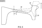
- FIG. 5 is a diagram exaggerating and illustrating the deformation generated in the wheel during braking in the embodiment.
- FIG. 1 is a vertical sectional view of a wheel according to an embodiment.
- FIG. 2 is a diagram schematically showing a wheel having a plate portion having an S-shaped cross section.
- FIG. 3 is a graph showing the relationship between the plate angle and the rim residual stress for Examples and Comparative Examples in which the value of the ratio of
- FIG. 6 is a diagram exaggeratingly exemplifying the deformation generated in the wheel during braking in an embodiment different from that in FIG.
- FIG. 7 is a diagram exaggerating and illustrating the deformation generated in the wheel during braking in the comparative example.
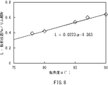
- FIG. 8 is a diagram showing a limit line in which the residual stress of the rim portion does not reverse in tension in the relationship between the plate angle and the ratio of the plate portion position to the rim width.
- the wheels according to the embodiment are used for railway vehicles.
- the wheel includes a boss portion, a rim portion, and a plate portion.
- the boss portion constitutes the inner peripheral portion of the wheel.
- the axle of the railroad vehicle is inserted into the boss portion.
- the rim portion constitutes the outer peripheral portion of the wheel.
- the rim portion includes a tread and a flange.
- the tread contacts the top surface of the rail on which the railroad vehicle travels.
- the flange projects outward from the tread in the radial direction of the wheel.
- the annular plate portion connects the boss portion and the rim portion.
- the center of the rim portion in the axial direction is arranged closer to the flange in the axial direction than the center of the boss portion in the axial direction.
- the axial direction is the direction in which the central axis of the wheel extends.
- the plate portion has a linear plate thickness center line in the vertical cross-sectional view of the wheel.
- the angle formed by the plate thickness center line in the axial direction is ⁇ , and the axial distance from the side surface of the rim portion on both sides in the axial direction opposite to the flange to the radial outer end of the plate thickness center line is Pw.
- the angle ⁇ is 90 ° when the plate thickness center line is parallel to the radial direction, and the plate thickness center line rotates in the radial direction from the position of 90 ° around the inner end in the radial direction to the opposite side of the flange. It is defined as less than 90 ° when tilted with respect to.
- the plate thickness center line of the plate portion is linear in the vertical cross-sectional view of the wheel and has no inflection point. That is, the plate portion connects the boss portion and the rim portion without substantially bending. Therefore, the weight of the plate portion can be reduced as compared with the case where the plate portion is curved. Therefore, the weight of the wheel can be reduced.
- the rim part thermally expands.
- the plate portion restrains the thermal expansion of the rim portion, thermal stress is generated in the rim portion. If the thermal stress of the rim portion becomes excessive, the rim portion may be plastically deformed during braking of the railroad vehicle, and after the rim portion is cooled, tensile residual stress in the circumferential direction of the wheel may occur.
- the wheel according to the first configuration is formed in a shape that relaxes the restraint of the rim portion by the plate portion.
- the angle of the plate thickness center line with respect to the axial direction of the wheel is assumed that the center of the rim portion is located closer to the flange than the center of the boss portion.
- the dimensions of each part are set so as to satisfy the equation (1) in consideration of both the position of the plate thickness center line with respect to the rim part.
- the plate thickness center line of the plate portion is linear in the vertical cross-sectional view of the wheel and has no inflection. In this case, stress concentration is unlikely to occur in the plate portion. Therefore, it is possible to reduce the thermal stress of the plate portion generated when the railroad vehicle is braked.
- the angle of the plate thickness center line of the plate portion with respect to the axial direction of the wheel is 90 ° or less. Therefore, the plate portion does not tilt inward in the orbit as it goes outward in the radial direction. Therefore, the rigidity of the plate portion can be ensured against the load received by the wheel from the rail in the axial direction when passing through the curve, in other words, the load received by the wheel from the inside of the track (lateral pressure). Therefore, the stress generated in the plate portion can be reduced.
- the angle ⁇ formed by the plate thickness center line in the axial direction is preferably 87 ° or less (second configuration).
- the angle of the plate thickness center line of the plate portion with respect to the axial direction of the wheel is 87 ° or less.
- the plate portion tilts to the outside of the track as it goes outward in the radial direction. Therefore, the rigidity of the plate portion with respect to the lateral pressure can be improved, and the stress generated in the plate portion can be further reduced. Further, since the necessity of increasing the plate thickness of the plate portion in order to secure the rigidity of the plate portion with respect to the lateral pressure is reduced, the weight of the plate portion and the wheels can be further reduced.
- the plate portion may have a plate thickness that becomes smaller toward the outside in the radial direction and becomes the minimum before the outer end of the plate thickness center line (third configuration).
- FIG. 1 is a vertical cross-sectional view of the wheel 100 according to the present embodiment.
- the vertical cross section means a cross section obtained by cutting the wheel 100 on a plane including the central axis X. Since the vertical cross section of the wheel 100 is symmetrical with respect to the central axis X, FIG. 1 shows only one side of the central axis X of the wheels 100.
- the direction in which the central axis X of the wheel 100 extends is referred to as an axial direction
- the radial direction and the circumferential direction of the wheel 100 are simply referred to as a radial direction and a circumferential direction, respectively.
- the wheel 100 is used for a railroad vehicle.
- the wheel 100 includes a boss portion 10, a rim portion 20, and a plate portion 30.
- the boss portion 10 constitutes the inner peripheral portion of the wheel 100.
- the boss portion 10 has a substantially cylindrical shape with the central axis X as the axis.
- An axle (not shown) of a railway vehicle is inserted into the boss portion 10.
- the rim portion 20 constitutes the outer peripheral portion of the wheel 100.
- the rim portion 20 is arranged outside the boss portion 10 in the radial direction.
- the rim portion 20 includes a tread surface 21 and a flange 22.
- the tread 21 and the flange 22 are provided on the outer peripheral surface of the rim portion 20.
- the tread 21 is a surface facing outward in the radial direction.
- the tread 21 contacts the top surface of the rail on which the railroad vehicle travels.
- the diameter of the tread 21 typically gradually increases toward the flange 22 side.
- the tread 21 may be, for example, a conical tread or an arc tread.
- the flange 22 is provided at one end in the axial direction of the rim portion 20.
- the flange 22 projects outward from the tread 21 in the radial direction.
- the flange 22 is positioned inside the left and right rails when the railroad vehicle travels on the rails.
- the side on which the flange 22 is arranged is referred to as the flange direction, and the opposite side thereof is referred to as the anti-flange direction.
- the rim portion 20 further includes both side surfaces 23 and 24 in the axial direction.
- the side surface 23 is a side surface on the flange 22 side
- the side surface 24 is a side surface opposite to the flange 22. That is, the side surface 23 is arranged in the flange direction with respect to the side surface 24.
- the side surface 24 sandwiches the tread surface 21 and the flange 22, and is arranged in the anti-flange direction with respect to the side surface 23.
- the rim portion 20 is arranged in the flange direction with respect to the boss portion 10. More specifically, the central Cr of the rim portion 20 in the axial direction is arranged closer to the flange 22 in the axial direction than the central Cb of the boss portion 10 in the axial direction. When the railroad vehicle travels, the central Cr of the rim portion 20 is positioned inside the central Cb of the boss portion 10 in the track width direction.
- the plate portion 30 forms a ring.
- the plate portion 30 connects the boss portion 10 and the rim portion 20.
- the plate thickness of the plate portion 30 is smaller than each of the boss width Wb and the rim width Wr as a whole.
- the plate thickness of the plate portion 30 is large on the boss portion 10 side and small on the rim portion 20 side.
- the boss width Wb means the length of the boss portion 10 in the axial direction.
- the rim width Wr is the length of the rim portion 20 in the axial direction, and is the maximum distance in the axial direction from the side surface 23 to the side surface 24 of the rim portion 20.
- the plate portion 30 includes both side surfaces 31 and 32 in the axial direction.
- the side surface 31 is a side surface on the flange 22 side
- the side surface 32 is a side surface opposite to the flange 22. That is, the side surface 31 is arranged in the flange direction with respect to the side surface 32.
- the side surface 32 is arranged in the anti-flange direction with respect to the side surface 31.
- the side surfaces 31 and 32 are preferably inclined with respect to the radial direction.
- the side surfaces 31 and 32 are connected to the rim portion 20 via the connecting portions 41 and 42, respectively.
- the side surfaces 31 and 32 are connected to the boss portion 10 via the connecting portions 43 and 44, respectively.
- Each of the connecting portions 41, 42, 43, 44 is substantially arcuate, for example, in a vertical cross-sectional view of the wheel 100.
- the end (R stop) 411 on the plate portion 30 side of the connection portion 41 and the end (R stop) 421 on the plate portion 30 side of the connection portion 42 those located more inward in the radial direction are used. It is defined as the outer peripheral edge of the plate portion 30.
- the end (R stop) 431 on the plate portion 30 side of the connection portion 43 and the end (R stop) 441 on the plate portion 30 side of the connection portion 44 the one located on the outer side in the radial direction is the plate portion 30. It is defined as the inner peripheral end of.
- the outer peripheral edge of the plate portion 30 can be said to be the base of the plate portion 30 with respect to the rim portion 20.
- the inner peripheral end of the plate portion 30 can be said to be the base of the plate portion 30 with respect to the boss portion 10.
- the end 411 of the connecting portion 41 and the end 441 of the connecting portion 44 are the outer peripheral end and the inner peripheral end of the plate portion 30, respectively.
- the plate thickness of the plate portion 30 decreases toward the outside in the radial direction and becomes the minimum before the outer peripheral end 411.
- the plate portion 30 has a minimum plate thickness inside the outer peripheral end 411 in the radial direction and in the vicinity of the outer peripheral end 411.
- the position where the plate thickness of the plate portion 30 is minimized substantially coincides with the position where the bending stress generated in the plate portion 30 due to the bending load received from the rail by the wheel 100 when the railroad vehicle passes the curve is minimized. do.
- the plate thickness of the plate portion 30 can be minimized at a position 5 mm to 30 mm inward in the radial direction from the outer peripheral end 411.
- the plate portion 30 has a plate thickness center line A.
- the plate thickness center line A is a line formed by connecting the plate thickness centers of the plate portions 30 extending from the boss portion 10 to the rim portion 20 in the vertical cross-sectional view of the wheel 100.
- the plate thickness center line A extends from the boss portion 10 side to the rim portion 20 side through the middle of the side surfaces 31 and 32.
- the plate thickness center line A is linear in the vertical cross-sectional view of the wheel 100.
- the linear shape here is a concept that includes not only a perfect straight line but also a very gentle arc having a radius of curvature of 1000 mm or more and a polygonal line.
- the plate thickness center line A may be anything that can be recognized as being substantially straight in the vertical cross-sectional view of the wheel 100. Since the plate thickness center line A is linear in the vertical cross-sectional view of the wheel 100, the plate portion 30 has a substantially flat plate shape and does not substantially bend in the axial direction.
- the plate thickness center line A has an outer end Aa in the radial direction and an inner end Ab in the radial direction.
- the outer end Aa is a point where the plate thickness center line A is connected to a straight line extending in the axial direction through the outer peripheral end 411 of the plate portion 30.
- the inner end Ab of the plate thickness center line A is a point where the plate thickness center line A is connected to a straight line extending in the axial direction through the inner peripheral end 441 of the plate portion 30.
- the position of the plate portion 30 with respect to the rim portion 20 is determined by the axial position of the outer end Aa of the plate thickness center line A.
- the distance in the axial direction from the side surface 24 in the anti-flange direction to the outer end Aa of the plate thickness center line A among the side surfaces 23 and 24 of the rim portion 20 is defined as the plate portion position Pw.
- the ratio of the plate portion position Pw to the rim width Wr: the smaller L Pw / Wr, the farther the outer peripheral end 411 of the plate portion 30 is from the flange 22, and the larger the ratio L, the more the outer peripheral end 411 of the plate portion 30 becomes the flange 22. Will be approaching.
- the ratio of the plate portion position Pw to the rim width Wr: L Pw / Wr is determined in relation to the angle ⁇ of the plate thickness center line A.
- the ratio L of the plate portion position Pw to the rim width Wr and the angle ⁇ of the plate thickness center line A are determined to satisfy the following equation (1). L ⁇ 0.0223 ⁇ -1.363 ... (1)
- the angle ⁇ of the plate thickness center line A is the angle formed by the plate thickness center line A with respect to the axial direction in the vertical cross-sectional view of the wheel 100.
- the angle ⁇ is the angle formed by the tangent line at the center of the plate thickness center line A (the intermediate point between the outer end Aa and the inner end Ab) with respect to the axial direction.
- the angle ⁇ is an angle formed by the longest line segment among the line segments constituting the plate thickness center line A with respect to the axial direction.
- the angle ⁇ is defined as 90 ° when the plate thickness center line A is parallel to the radial direction.
- the angle ⁇ is set when the plate thickness center line A is tilted with respect to the radial direction. Defined to be less than 90 °. That is, when the outer end Aa of the plate thickness center line A is arranged in the anti-flange direction with respect to the position where the angle ⁇ is 90 °, it is assumed that the angle ⁇ is less than 90 °.
- the angle ⁇ of the plate thickness center line A is set to 90 ° or less. Although it depends on the specifications of the tread brake used for the wheel 100, the angle ⁇ is preferably 87 ° or less. As the angle ⁇ becomes smaller and the plate portion 30 tilts in the direction opposite to the flange, the restraint of the rim portion 20 by the plate portion 30 is relaxed, and the deformation of the rim portion 20 during braking of the railway vehicle becomes easier to be allowed. From the viewpoint of manufacturability of the wheel 100, the angle ⁇ is preferably 75 ° or more.
- the ratio L of the plate portion position Pw to the rim width Wr becomes larger and the base of the plate portion 30 with respect to the rim portion 20 approaches the flange 22, the restraint of the rim portion 20 by the plate portion 30 is relaxed, and the braking of the railway vehicle is performed. Deformation of the rim portion 20 inside is easily allowed.
- the ratio L is preferably set in the range of 0.3 or more and 0.7 or less from the viewpoint of manufacturability of the wheel 100 and the like.
- both the angle ⁇ of the plate thickness center line A and the ratio L of the plate portion position Pw to the rim width Wr are set so that the restraint of the rim portion 20 by the plate portion 30 is relaxed. It is set properly.
- the central Cr of the rim portion 20 is located closer to the flange 22 than the central Cb of the boss portion 10, and the plate portion 30 and the plate thickness center line A thereof are located on the wheel 100.
- the angle ⁇ of the plate thickness center line A and the ratio L of the plate portion position Pw to the rim width Wr are set so as to satisfy the relationship of the above equation (1) on the premise that the plate is linear in the vertical cross section. ing.
- the plate portion The degree of restraint of the rim portion 20 by 30 can be effectively reduced. Therefore, when the brake shoe of the tread brake is pressed against the tread surface 21 of the rim portion 20 to generate frictional heat, the thermal expansion of the rim portion 20 is less likely to be hindered. Therefore, when the tread brake is used for braking the railway vehicle, the thermal stress of the rim portion 20 generated by the tread brake can be reduced, and the plastic deformation of the rim portion 20 can be suppressed. As a result, after the rim portion 20 is cooled, it is possible to prevent the residual stress of the rim portion 20 from reversing in tension.
- the plate thickness center line A of the plate portion 30 is linear in the vertical cross-sectional view of the wheel 100 and has no inflection point. That is, the plate portion 30 connects the boss portion 10 and the rim portion 20 without being substantially curved. Therefore, the weight of the plate portion 30 can be reduced as compared with the case where the plate portion 30 is curved. Therefore, the weight of the wheel 100 can be reduced.
- the plate thickness center line A is linear and the plate portion 30 is not substantially curved, stress concentration in the plate portion 30 can be alleviated during braking of the railway vehicle by the tread brake. Therefore, it is possible to reduce the thermal stress of the plate portion 30 generated when the railroad vehicle is braked.
- the plate portion 30 when the plate portion 30 is tilted in the flange direction (inside the track) as it goes outward in the radial direction, the load that the wheel 100 receives from the rail in the axial direction when passing through a curve, that is, the wheel 100 is pushed in the flange direction by the rail.
- the rigidity of the plate portion 30 with respect to a load becomes low.
- the angle ⁇ of the plate thickness center line A is set to 90 ° or less, the plate portion 30 does not substantially tilt in the flange direction as it goes outward in the radial direction. .. Therefore, the rigidity of the plate portion 30 with respect to the lateral pressure can be ensured. Therefore, the stress generated in the plate portion 30 can be reduced.
- the angle ⁇ of the plate thickness center line A is preferably 87 ° or less.
- the plate portion 30 is tilted in the anti-flange direction (outside the track) toward the outside in the radial direction.
- the rigidity of the plate portion 30 with respect to the lateral pressure can be improved, and the stress generated in the plate portion 30 can be further reduced.
- the rim portion 20 is a plate. It becomes easy to be restrained by the portion 30. Therefore, it is preferable that the side surfaces 31 and 32 of the plate portion 30 are inclined with respect to the radial direction of the wheel 100. Each of the side surfaces 31 and 32 may be inclined with respect to the radial direction so as to be toward the anti-flange direction (outside the track) as it approaches the rim portion 20, for example. By inclining the side surfaces 31 and 32 in the radial direction, the restraint of the rim portion 20 by the plate portion 30 can be further relaxed.
- the plate thickness of the plate portion 30 decreases toward the outside in the radial direction, and becomes the minimum before the outer end Aa of the plate thickness center line A. More specifically, in the plate portion 30, the position where the bending stress generated by the bending load received from the rail when passing through the curve is minimized and the position where the plate thickness is minimized are substantially matched. By doing so, it is possible to prevent fatigue fracture of the plate portion 30 and improve the durability of the wheel 100.
- FIG. 2 is a diagram schematically showing a wheel having a plate portion having an S-shaped cross section. Table 1 shows the conditions for the parameters ⁇ and L.
- FEM analysis was performed using general-purpose software (ABAQUS Ver.6.12, manufactured by Dassault Systèmes).
- ABAQUS Ver.6.12 manufactured by Dassault Systèmes.
- the braking time was 1200 seconds, and the inner circumference of the wheel was completely restrained.
- Table 2 shows the residual stress (rim residual stress) of the rim portion obtained by FEM analysis.
- the rim residual stress indicates the maximum circumferential stress of the rim portion after braking and cooling. If the rim residual stress is a negative value, it means that the residual stress of the rim part is compressed even after braking, and if the rim residual stress is a positive value, it means that the residual stress of the rim part has turned to tension after braking. ing.
- FIG. 3 is a graph showing the relationship between the plate angle ⁇ and the rim residual stress for Example 1, Comparative Example 1, and Comparative Example 2 in which the value of the ratio L of the plate portion position Pw to the rim width Wr is equal.
- the value of the rim residual stress increases as the plate angle ⁇ increases. Therefore, it can be said that if the plate angle ⁇ becomes smaller, the possibility that the residual stress of the rim portion turns into tension after braking of the railway vehicle is reduced.
- FIG. 4 is a graph showing the relationship between the ratio L of the plate portion position Pw to the rim width Wr and the rim residual stress for Example 3, Comparative Example 2, and Comparative Example 3 having the same plate angle ⁇ .
- FIG. 4 it can be seen that the larger the ratio L of the plate portion position Pw to the rim width Wr, the smaller the value of the rim residual stress. Therefore, it can be said that the larger the ratio L, the lower the possibility that the residual stress of the rim portion turns into tension after braking the railway vehicle.
- FIGS. 5 to 7 are diagrams illustrating and exemplifying the deformation that occurs in the wheel during braking in Example 1, Example 2, and Comparative Example 2, respectively.
- Example 1 where the plate angle ⁇ is as small as 80 °, as shown in FIG. 5, when the heat flux is applied to the tread surface 21, the rim portion 20 moves significantly in the flange direction. That is, in Example 1, since the plate angle ⁇ is small, the restraint of the plate portion 30 with respect to the movement of the rim portion 20 in the flange direction is reduced, and the thermal expansion of the rim portion 20 can be allowed. Therefore, in the first embodiment, the thermal stress generated in the rim portion 20 during braking is reduced, and the residual stress of the rim portion 20 remains compressed even after braking.
- Example 2 where the ratio L of the plate portion position Pw to the rim width Wr is 0.580, which is relatively large, as shown in FIG. 6, when the heat flux is applied to the tread surface 21, the rim portion 20 rotates in the flange direction. .. That is, in Example 2, since the ratio L was secured, the restraint of the plate portion 30 with respect to the rotation of the rim portion 20 in the flange direction was reduced, and the thermal expansion of the rim portion 20 could be allowed. Therefore, in the second embodiment, the thermal stress generated in the rim portion 20 during braking is reduced, and the residual stress of the rim portion 20 remains compressed even after braking.
- Comparative Example 2 in which the plate angle ⁇ is 90 °, which is larger than that of Example 1, and the ratio L of the plate portion position Pw to the rim width Wr is 0.448, which is smaller than that of Example 2. Then, as shown in FIG. 7, the movement and rotation of the rim portion 20 hardly occurred.
- the plate portion 30 was largely restrained by the movement and rotation of the rim portion 20, and when a heat flux was applied to the tread surface 21, the thermal expansion of the rim portion 20 was hindered. Therefore, in Comparative Example 2, the thermal stress generated in the rim portion 20 during braking became large, and the residual stress in the rim portion 20 was reversed to tension after braking.
- FIG. 8 shows a limit line in which the residual stress of the rim portion does not reverse to tension in the relationship between the plate angle ⁇ and the ratio L.
- the rim residual stress becomes compression. Therefore, the case where the residual stress of the rim portion can be substantially prevented from becoming tension is the case where the plate angle ⁇ and the ratio L satisfy the following equation (1).
- the plate angle ⁇ is 90 ° or less.
Landscapes
- Engineering & Computer Science (AREA)
- Mechanical Engineering (AREA)
- Braking Arrangements (AREA)
Abstract
A wheel (100) is provided with a boss portion (10), a rim portion (20), and a plate portion (30). The rim portion (20) includes a tread (21) and a flange (22). A center (Cr) of the rim portion (20) in an axial direction of the wheel (100) is arranged closer to the flange (22) in the axial direction than a center (Cb) of the boss portion (10) in the axial direction. The plate portion (30) has a plate thickness central line (A) which is linear in a vertical cross-sectional view of the wheel (100). The wheel (100) satisfies L ≥ 0.0223α - 1.363, wherein α is the angle the plate thickness central line (A) forms with the axial direction, Pw is the distance in the axial direction between a lateral face (24) of the rim portion (20) and an outer end (Aa) of the plate thickness central line (A), Wr is the length of the rim portion (20) in the axial direction, and L is Pw/Wr. The angle α is no greater than 90°.
Description
本開示は、鉄道車両に用いられる車輪に関する。
This disclosure relates to wheels used in railway vehicles.
鉄道車両の制動方式の一種として、踏面ブレーキが知られている。踏面ブレーキとは、鉄道車両の車輪の踏面に制輪子を押し付けることにより、踏面と制輪子との間に摩擦力を発生させ、その摩擦力で鉄道車両を制動する制動方式である。
Tread brakes are known as a type of braking method for railway vehicles. The tread brake is a braking method in which a brake shoe is pressed against the tread surface of a wheel of a railroad vehicle to generate a frictional force between the tread and the brake shoe, and the frictional force brakes the railroad vehicle.
踏面ブレーキを利用して鉄道車両を制動する場合、踏面と制輪子との間で摩擦熱が発生するため、車輪、特に車輪の外周部を構成するリム部の温度が上昇する。これにより、リム部の熱膨張が生じ、リム部において熱応力が発生する。この熱応力を低減するため、従来、種々の車輪形状が提案されている。
When braking a railroad vehicle using a tread brake, frictional heat is generated between the tread and the brake shoes, so the temperature of the wheels, especially the rims that make up the outer periphery of the wheels, rises. As a result, thermal expansion of the rim portion occurs, and thermal stress is generated in the rim portion. In order to reduce this thermal stress, various wheel shapes have been conventionally proposed.
例えば、特許文献1では、車輪の外周部を構成するリム部と、車輪の内周部を構成するボス部と、概略S字状の断面を有する板部とを備える車輪が提案されている。特許文献1の車輪では、板部及びリム部の熱応力の低減を目的として、ボス部に対するリム部の変位量、及び板部のリム部側の変位量がそれぞれ所定の値以上に設定されている。ボス部に対するリム部の変位量は、板部の曲線状の板厚中心線のリム部側の端部から車輪の軸心に下ろした垂線と、板厚中心線のボス部側の端部から車輪の軸心に下ろした垂線との間の距離である。板部のリム部側の変位量は、板厚中心線のリム部側の端部から車輪の軸心に下ろした垂線と、車輪の軸方向におけるリム部の中央から車輪の軸心に下ろした垂線との間の距離である。
For example, Patent Document 1 proposes a wheel including a rim portion forming an outer peripheral portion of the wheel, a boss portion forming an inner peripheral portion of the wheel, and a plate portion having a substantially S-shaped cross section. In the wheel of Patent Document 1, the displacement amount of the rim portion with respect to the boss portion and the displacement amount of the plate portion on the rim portion side are set to predetermined values or more for the purpose of reducing the thermal stress of the plate portion and the rim portion. There is. The amount of displacement of the rim with respect to the boss is from the vertical line drawn from the end of the curved plate thickness center line on the rim side to the axis of the wheel and the end of the plate thickness center line on the boss side. It is the distance between the vertical line drawn down to the axis of the wheel. The amount of displacement of the plate portion on the rim portion side is the vertical line drawn from the end of the plate thickness center line on the rim portion side to the axis of the wheel and the displacement amount from the center of the rim portion in the axial direction of the wheel to the axis of the wheel. The distance between the vertical line.
例えば、特許文献2では、リム部の熱応力の低減を目的として、湾曲した断面形状を板部に持たせた車輪が提案されている。特許文献2の車輪において、板部は、ベル型と呼ばれる断面形状を有する。この板部の曲線状の板厚中心線の両端は、車輪の中央平面(車輪の軸心に垂直な平面)に対して同じ側に配置される。一方、板厚中心線の中間点は、車輪の中央平面に対して板厚中心線の両端と反対側に配置される。
For example, Patent Document 2 proposes a wheel having a curved cross-sectional shape on a plate portion for the purpose of reducing thermal stress of the rim portion. In the wheel of Patent Document 2, the plate portion has a cross-sectional shape called a bell shape. Both ends of the curved plate thickness center line of the plate portion are arranged on the same side with respect to the central plane of the wheel (the plane perpendicular to the axis of the wheel). On the other hand, the midpoint of the plate thickness center line is arranged on the side opposite to both ends of the plate thickness center line with respect to the center plane of the wheel.
ところで、鉄道車両に用いられる車輪のリム部には、製造時に熱処理等が施されることにより、通常、圧縮残留応力が付与されている。しかしながら、踏面ブレーキによって鉄道車両が制動された際、リム部に高い熱応力が発生して塑性変形が生じると、リム部の圧縮残留応力が引張残留応力に反転することがある。すなわち、鉄道車両の制動中には、踏面と制輪子との摩擦により、リム部で温度が上昇してリム部が熱膨張をしようとする一方、車輪の内周側では温度上昇が小さいため、リム部の熱膨張が阻害され、リム部において特に車輪の円周方向の圧縮応力が発生する。この圧縮応力が降伏点を超えるとリム部の塑性変形が生じ、リム部が冷却された後、圧縮応力が引張応力に反転してリム部に残留応力として作用する。リム部に引張残留応力が発生した状態で、踏面にき裂が生じると、発生したき裂が車輪の内部まで進展する可能性が考えられる。よって、鉄道車両の制動に踏面ブレーキを使用する際には、踏面ブレーキに起因してリム部に発生する熱応力を低減し、リム部における引張残留応力の発生を抑制する必要がある。
By the way, the rim portion of a wheel used in a railroad vehicle is usually subjected to compressive residual stress by heat treatment or the like at the time of manufacture. However, when a railroad vehicle is braked by a tread brake, if high thermal stress is generated in the rim portion and plastic deformation occurs, the compressive residual stress of the rim portion may be reversed to the tensile residual stress. That is, during braking of a railroad vehicle, the friction between the tread and the brake shoe causes the temperature to rise at the rim portion and the rim portion tries to thermally expand, while the temperature rise is small on the inner peripheral side of the wheel. The thermal expansion of the rim portion is hindered, and a compressive stress in the circumferential direction of the wheel is generated particularly in the rim portion. When this compressive stress exceeds the yield point, plastic deformation of the rim portion occurs, and after the rim portion is cooled, the compressive stress reverses to the tensile stress and acts as residual stress on the rim portion. If cracks occur in the tread while tensile residual stress is generated in the rim portion, it is possible that the generated cracks may extend to the inside of the wheel. Therefore, when the tread brake is used for braking a railway vehicle, it is necessary to reduce the thermal stress generated in the rim portion due to the tread brake and suppress the generation of tensile residual stress in the rim portion.
特許文献1及び2の車輪は、いずれも、湾曲形状の板部を有している。これにより、リム部の熱膨張に対する板部の拘束が緩和される。よって、特許文献1及び2の車輪では、鉄道車両の制動時にリム部に発生する熱応力が低減され、引張残留応力がリム部に発生しにくくなると考えられる。しかしながら、板部を湾曲させた場合、車輪の重量が増加するという問題がある。
Both the wheels of Patent Documents 1 and 2 have a curved plate portion. As a result, the restraint of the plate portion with respect to the thermal expansion of the rim portion is relaxed. Therefore, in the wheels of Patent Documents 1 and 2, it is considered that the thermal stress generated in the rim portion during braking of the railway vehicle is reduced and the tensile residual stress is less likely to be generated in the rim portion. However, when the plate portion is curved, there is a problem that the weight of the wheel increases.
本開示は、軽量化と、リム部における引張残留応力の発生の抑制とを両立することができる車輪を提供することを課題とする。
It is an object of the present disclosure to provide a wheel capable of achieving both weight reduction and suppression of generation of tensile residual stress in the rim portion.
本開示に係る車輪は、鉄道車両に用いられる。車輪は、ボス部と、リム部と、板部と、を備える。ボス部は、車輪の内周部を構成する。ボス部には、鉄道車両の車軸が挿入される。リム部は、車輪の外周部を構成する。リム部は、踏面と、フランジと、を含む。踏面は、鉄道車両が走行するレールの頭頂面に接触する。フランジは、車輪の半径方向で踏面よりも外側に突出する。環状の板部は、ボス部とリム部とを接続する。軸方向におけるリム部の中央は、軸方向におけるボス部の中央よりも、軸方向においてフランジ寄りに配置されている。軸方向は、車輪の中心軸が延びる方向である。板部は、車輪の縦断面視で直線状の板厚中心線を有する。板厚中心線が軸方向となす角度をαとし、リム部の軸方向の両側面のうちフランジと反対側の側面から、板厚中心線の半径方向の外端までの軸方向における距離をPwとし、軸方向におけるリム部の長さをWrとし、Pw/WrをLとしたとき、本開示に係る車輪は、以下の式(1)を満たす。
L≧0.0223α-1.363・・・(1)
ただし、角度αは、90°以下である。角度αは、板厚中心線が半径方向と平行な場合に90°であり、板厚中心線が90°の位置から半径方向の内端を中心としてフランジの反対側に回転することで半径方向に対して傾いている場合に90°未満であると定義される。 The wheels according to the present disclosure are used for railway vehicles. The wheel includes a boss portion, a rim portion, and a plate portion. The boss portion constitutes the inner peripheral portion of the wheel. The axle of the railroad vehicle is inserted into the boss portion. The rim portion constitutes the outer peripheral portion of the wheel. The rim portion includes a tread and a flange. The tread contacts the top surface of the rail on which the railroad vehicle travels. The flange projects outward from the tread in the radial direction of the wheel. The annular plate portion connects the boss portion and the rim portion. The center of the rim portion in the axial direction is arranged closer to the flange in the axial direction than the center of the boss portion in the axial direction. The axial direction is the direction in which the central axis of the wheel extends. The plate portion has a linear plate thickness center line in the vertical cross-sectional view of the wheel. The angle formed by the plate thickness center line in the axial direction is α, and the axial distance from the side surface of the rim portion on both sides in the axial direction opposite to the flange to the radial outer end of the plate thickness center line is Pw. When the length of the rim portion in the axial direction is Wr and Pw / Wr is L, the wheel according to the present disclosure satisfies the following equation (1).
L ≧ 0.0223α-1.363 ... (1)
However, the angle α is 90 ° or less. The angle α is 90 ° when the plate thickness center line is parallel to the radial direction, and the plate thickness center line rotates in the radial direction from the position of 90 ° around the inner end in the radial direction to the opposite side of the flange. It is defined as less than 90 ° when tilted with respect to.
本開示によれば、車輪の軽量化と、リム部における引張残留応力の発生の抑制とを両立することができる。
According to the present disclosure, it is possible to achieve both weight reduction of the wheel and suppression of generation of tensile residual stress in the rim portion.
実施形態(第1の構成)に係る車輪は、鉄道車両に用いられる。車輪は、ボス部と、リム部と、板部と、を備える。ボス部は、車輪の内周部を構成する。ボス部には、鉄道車両の車軸が挿入される。リム部は、車輪の外周部を構成する。リム部は、踏面と、フランジと、を含む。踏面は、鉄道車両が走行するレールの頭頂面に接触する。フランジは、車輪の半径方向で踏面よりも外側に突出する。環状の板部は、ボス部とリム部とを接続する。軸方向におけるリム部の中央は、軸方向におけるボス部の中央よりも、軸方向においてフランジ寄りに配置されている。軸方向は、車輪の中心軸が延びる方向である。板部は、車輪の縦断面視で直線状の板厚中心線を有する。板厚中心線が軸方向となす角度をαとし、リム部の軸方向の両側面のうちフランジと反対側の側面から、板厚中心線の半径方向の外端までの軸方向における距離をPwとし、軸方向におけるリム部の長さをWrとし、Pw/WrをLとしたとき、第1の構成に係る車輪は、以下の式(1)を満たす。
L≧0.0223α-1.363・・・(1)
ただし、角度αは、90°以下である。角度αは、板厚中心線が半径方向と平行な場合に90°であり、板厚中心線が90°の位置から半径方向の内端を中心としてフランジの反対側に回転することで半径方向に対して傾いている場合に90°未満であると定義される。 The wheels according to the embodiment (first configuration) are used for railway vehicles. The wheel includes a boss portion, a rim portion, and a plate portion. The boss portion constitutes the inner peripheral portion of the wheel. The axle of the railroad vehicle is inserted into the boss portion. The rim portion constitutes the outer peripheral portion of the wheel. The rim portion includes a tread and a flange. The tread contacts the top surface of the rail on which the railroad vehicle travels. The flange projects outward from the tread in the radial direction of the wheel. The annular plate portion connects the boss portion and the rim portion. The center of the rim portion in the axial direction is arranged closer to the flange in the axial direction than the center of the boss portion in the axial direction. The axial direction is the direction in which the central axis of the wheel extends. The plate portion has a linear plate thickness center line in the vertical cross-sectional view of the wheel. The angle formed by the plate thickness center line in the axial direction is α, and the axial distance from the side surface of the rim portion on both sides in the axial direction opposite to the flange to the radial outer end of the plate thickness center line is Pw. When the length of the rim portion in the axial direction is Wr and Pw / Wr is L, the wheel according to the first configuration satisfies the following equation (1).
L ≧ 0.0223α-1.363 ... (1)
However, the angle α is 90 ° or less. The angle α is 90 ° when the plate thickness center line is parallel to the radial direction, and the plate thickness center line rotates in the radial direction from the position of 90 ° around the inner end in the radial direction to the opposite side of the flange. It is defined as less than 90 ° when tilted with respect to.
第1の構成に係る車輪において、板部の板厚中心線は、車輪の縦断面視で直線状であり、変曲点を有しない。すなわち、板部は、実質的に湾曲せずにボス部とリム部とを接続する。そのため、板部を湾曲させた場合と比較し、板部の重量を低減することができる。よって、車輪を軽量化することができる。
In the wheel according to the first configuration, the plate thickness center line of the plate portion is linear in the vertical cross-sectional view of the wheel and has no inflection point. That is, the plate portion connects the boss portion and the rim portion without substantially bending. Therefore, the weight of the plate portion can be reduced as compared with the case where the plate portion is curved. Therefore, the weight of the wheel can be reduced.
車輪のリム部の踏面に踏面ブレーキの制輪子が押し付けられて摩擦熱が発生したとき、リム部が熱膨張する。このリム部の熱膨張を板部が拘束することにより、リム部に熱応力が発生する。リム部の熱応力が過大となると、鉄道車両の制動中にリム部が塑性変形して、リム部が冷却された後に車輪の円周方向における引張残留応力が生じ得る。一方、第1の構成に係る車輪は、板部によるリム部の拘束を緩和するような形状に形成されている。より具体的には、第1の構成に係る車輪では、リム部の中央がボス部の中央よりもフランジ寄りに位置することを前提として、車輪の軸方向に対する板部の板厚中心線の角度と、リム部に対する板厚中心線の位置との双方を考慮した式(1)を満たすように各部の寸法が設定されている。これにより、板部によるリム部の拘束を効果的に緩和し、制動時におけるリム部の熱膨張を許容することができる。よって、リム部の熱応力を低減することができ、リム部の塑性変形を抑制することができる。そのため、鉄道車両の制動後にリム部が冷却されたとき、リム部の残留応力が引張に反転するのを抑制することができる。
When the brake shoe of the tread brake is pressed against the tread surface of the rim part of the wheel and frictional heat is generated, the rim part thermally expands. When the plate portion restrains the thermal expansion of the rim portion, thermal stress is generated in the rim portion. If the thermal stress of the rim portion becomes excessive, the rim portion may be plastically deformed during braking of the railroad vehicle, and after the rim portion is cooled, tensile residual stress in the circumferential direction of the wheel may occur. On the other hand, the wheel according to the first configuration is formed in a shape that relaxes the restraint of the rim portion by the plate portion. More specifically, in the wheel according to the first configuration, the angle of the plate thickness center line with respect to the axial direction of the wheel is assumed that the center of the rim portion is located closer to the flange than the center of the boss portion. The dimensions of each part are set so as to satisfy the equation (1) in consideration of both the position of the plate thickness center line with respect to the rim part. As a result, the restraint of the rim portion by the plate portion can be effectively relaxed, and the thermal expansion of the rim portion during braking can be allowed. Therefore, the thermal stress of the rim portion can be reduced, and the plastic deformation of the rim portion can be suppressed. Therefore, when the rim portion is cooled after braking of the railway vehicle, it is possible to suppress the residual stress of the rim portion from reversing to tension.
このように、第1の構成に係る車輪によれば、車輪の軽量化と、リム部における引張残留応力の発生の抑制とを両立することができる。
As described above, according to the wheel according to the first configuration, it is possible to achieve both the weight reduction of the wheel and the suppression of the generation of tensile residual stress in the rim portion.
上述した通り、第1の構成に係る車輪では、板部の板厚中心線は、車輪の縦断面視で直線状であり、変曲点を有しない。この場合、板部において応力集中が生じにくい。そのため、鉄道車両の制動時に発生する板部の熱応力を低減することができる。
As described above, in the wheel according to the first configuration, the plate thickness center line of the plate portion is linear in the vertical cross-sectional view of the wheel and has no inflection. In this case, stress concentration is unlikely to occur in the plate portion. Therefore, it is possible to reduce the thermal stress of the plate portion generated when the railroad vehicle is braked.
第1の構成によれば、車輪の軸方向に対する板部の板厚中心線の角度が90°以下となっている。そのため、板部が半径方向外側に向かうにつれて軌道内側に傾くことがない。よって、曲線通過時に車輪がレールからその軸方向に受ける荷重、言い換えると軌道内側から車輪が受ける荷重(横圧)に対し、板部の剛性を確保することができる。そのため、板部に発生する応力を低減することができる。
According to the first configuration, the angle of the plate thickness center line of the plate portion with respect to the axial direction of the wheel is 90 ° or less. Therefore, the plate portion does not tilt inward in the orbit as it goes outward in the radial direction. Therefore, the rigidity of the plate portion can be ensured against the load received by the wheel from the rail in the axial direction when passing through the curve, in other words, the load received by the wheel from the inside of the track (lateral pressure). Therefore, the stress generated in the plate portion can be reduced.
板厚中心線が軸方向となす角度αは、87°以下であることが好ましい(第2の構成)。
The angle α formed by the plate thickness center line in the axial direction is preferably 87 ° or less (second configuration).
第2の構成によれば、車輪の軸方向に対する板部の板厚中心線の角度が87°以下となっている。この場合、板部が半径方向外側に向かうにつれて軌道外側に傾くことになる。よって、横圧に対する板部の剛性を向上させることができ、板部に発生する応力をより低減することができる。また、横圧に対する板部の剛性を確保するために板部の板厚を増加させる必要性が低下するため、板部及び車輪をより軽量化することができる。
According to the second configuration, the angle of the plate thickness center line of the plate portion with respect to the axial direction of the wheel is 87 ° or less. In this case, the plate portion tilts to the outside of the track as it goes outward in the radial direction. Therefore, the rigidity of the plate portion with respect to the lateral pressure can be improved, and the stress generated in the plate portion can be further reduced. Further, since the necessity of increasing the plate thickness of the plate portion in order to secure the rigidity of the plate portion with respect to the lateral pressure is reduced, the weight of the plate portion and the wheels can be further reduced.
板部は、半径方向の外側に向かうにつれて小さくなり板厚中心線の外端の手前で最小となる板厚を有していてもよい(第3の構成)。
The plate portion may have a plate thickness that becomes smaller toward the outside in the radial direction and becomes the minimum before the outer end of the plate thickness center line (third configuration).
以下、本開示の実施形態について、図面を参照しつつ説明する。各図において同一又は相当の構成については同一符号を付し、同じ説明を繰り返さない。
Hereinafter, embodiments of the present disclosure will be described with reference to the drawings. In each figure, the same or equivalent configurations are designated by the same reference numerals, and the same description is not repeated.
図1は、本実施形態に係る車輪100の縦断面図である。縦断面とは、中心軸Xを含む平面で車輪100を切断した断面をいう。車輪100の縦断面は中心軸Xに対して対称であるので、図1では、車輪100のうち中心軸Xの片側のみを示す。以下、車輪100の中心軸Xが延びる方向を軸方向といい、車輪100の半径方向及び円周方向をそれぞれ単に半径方向及び円周方向という。
FIG. 1 is a vertical cross-sectional view of the wheel 100 according to the present embodiment. The vertical cross section means a cross section obtained by cutting the wheel 100 on a plane including the central axis X. Since the vertical cross section of the wheel 100 is symmetrical with respect to the central axis X, FIG. 1 shows only one side of the central axis X of the wheels 100. Hereinafter, the direction in which the central axis X of the wheel 100 extends is referred to as an axial direction, and the radial direction and the circumferential direction of the wheel 100 are simply referred to as a radial direction and a circumferential direction, respectively.
図1を参照して、車輪100は鉄道車両に用いられる。車輪100は、ボス部10と、リム部20と、板部30とを備える。
With reference to FIG. 1, the wheel 100 is used for a railroad vehicle. The wheel 100 includes a boss portion 10, a rim portion 20, and a plate portion 30.
ボス部10は、車輪100の内周部を構成する。ボス部10は、中心軸Xを軸心とする概略円筒状をなす。ボス部10には、鉄道車両の車軸(図示略)が挿入される。
The boss portion 10 constitutes the inner peripheral portion of the wheel 100. The boss portion 10 has a substantially cylindrical shape with the central axis X as the axis. An axle (not shown) of a railway vehicle is inserted into the boss portion 10.
リム部20は、車輪100の外周部を構成する。リム部20は、半径方向においてボス部10の外側に配置される。リム部20は、踏面21と、フランジ22とを含んでいる。踏面21及びフランジ22は、リム部20の外周面に設けられている。
The rim portion 20 constitutes the outer peripheral portion of the wheel 100. The rim portion 20 is arranged outside the boss portion 10 in the radial direction. The rim portion 20 includes a tread surface 21 and a flange 22. The tread 21 and the flange 22 are provided on the outer peripheral surface of the rim portion 20.
踏面21は、半径方向で外向きの面である。踏面21は、鉄道車両が走行するレールの頭頂面に接触する。踏面21の直径は、典型的には、フランジ22側に向かって徐々に大きくなる。踏面21は、例えば、円すい踏面であってもよいし、円弧踏面であってもよい。
The tread 21 is a surface facing outward in the radial direction. The tread 21 contacts the top surface of the rail on which the railroad vehicle travels. The diameter of the tread 21 typically gradually increases toward the flange 22 side. The tread 21 may be, for example, a conical tread or an arc tread.
フランジ22は、リム部20において軸方向の一方端部に設けられる。フランジ22は、半径方向で踏面21よりも外側に突出している。フランジ22は、鉄道車両がレール上を走行するとき、左右のレールの内側に位置付けられる。以下、車輪100の軸方向において、フランジ22が配置される側をフランジ方向、これの反対側を反フランジ方向という。
The flange 22 is provided at one end in the axial direction of the rim portion 20. The flange 22 projects outward from the tread 21 in the radial direction. The flange 22 is positioned inside the left and right rails when the railroad vehicle travels on the rails. Hereinafter, in the axial direction of the wheel 100, the side on which the flange 22 is arranged is referred to as the flange direction, and the opposite side thereof is referred to as the anti-flange direction.
リム部20は、軸方向の両側面23,24をさらに含む。側面23は、フランジ22側の側面であり、側面24は、フランジ22と反対側の側面である。すなわち、側面23は、側面24に対してフランジ方向に配置されている。側面24は、踏面21及びフランジ22を挟み、側面23に対して反フランジ方向に配置されている。
The rim portion 20 further includes both side surfaces 23 and 24 in the axial direction. The side surface 23 is a side surface on the flange 22 side, and the side surface 24 is a side surface opposite to the flange 22. That is, the side surface 23 is arranged in the flange direction with respect to the side surface 24. The side surface 24 sandwiches the tread surface 21 and the flange 22, and is arranged in the anti-flange direction with respect to the side surface 23.
リム部20は、ボス部10に対してフランジ方向に配置されている。より詳細には、軸方向におけるリム部20の中央Crは、軸方向におけるボス部10の中央Cbよりも、軸方向においてフランジ22寄りに配置されている。鉄道車両が走行する際、リム部20の中央Crは、ボス部10の中央Cbに対して軌道幅方向の内側に位置付けられる。
The rim portion 20 is arranged in the flange direction with respect to the boss portion 10. More specifically, the central Cr of the rim portion 20 in the axial direction is arranged closer to the flange 22 in the axial direction than the central Cb of the boss portion 10 in the axial direction. When the railroad vehicle travels, the central Cr of the rim portion 20 is positioned inside the central Cb of the boss portion 10 in the track width direction.
板部30は、環状をなす。板部30は、ボス部10とリム部20とを接続する。板部30の板厚は、全体として、ボス幅Wb及びリム幅Wrの各々よりも小さい。板部30の板厚は、ボス部10側で大きく、リム部20側で小さくなっている。ボス幅Wbとは、軸方向におけるボス部10の長さをいう。リム幅Wrは、軸方向におけるリム部20の長さであり、リム部20の側面23から側面24までの軸方向における最大距離である。
The plate portion 30 forms a ring. The plate portion 30 connects the boss portion 10 and the rim portion 20. The plate thickness of the plate portion 30 is smaller than each of the boss width Wb and the rim width Wr as a whole. The plate thickness of the plate portion 30 is large on the boss portion 10 side and small on the rim portion 20 side. The boss width Wb means the length of the boss portion 10 in the axial direction. The rim width Wr is the length of the rim portion 20 in the axial direction, and is the maximum distance in the axial direction from the side surface 23 to the side surface 24 of the rim portion 20.
板部30は、軸方向の両側面31,32を含んでいる。側面31は、フランジ22側の側面であり、側面32は、フランジ22と反対側の側面である。すなわち、側面31は、側面32に対してフランジ方向に配置されている。側面32は、側面31に対して反フランジ方向に配置されている。車輪100の縦断面視で、側面31,32は、半径方向に対して傾斜していることが好ましい。側面31,32は、それぞれ、接続部41,42を介してリム部20に接続される。側面31,32は、それぞれ、接続部43,44を介してボス部10に接続される。接続部41,42,43,44の各々は、例えば、車輪100の縦断面視で実質的に円弧状をなす。
The plate portion 30 includes both side surfaces 31 and 32 in the axial direction. The side surface 31 is a side surface on the flange 22 side, and the side surface 32 is a side surface opposite to the flange 22. That is, the side surface 31 is arranged in the flange direction with respect to the side surface 32. The side surface 32 is arranged in the anti-flange direction with respect to the side surface 31. In a vertical cross-sectional view of the wheel 100, the side surfaces 31 and 32 are preferably inclined with respect to the radial direction. The side surfaces 31 and 32 are connected to the rim portion 20 via the connecting portions 41 and 42, respectively. The side surfaces 31 and 32 are connected to the boss portion 10 via the connecting portions 43 and 44, respectively. Each of the connecting portions 41, 42, 43, 44 is substantially arcuate, for example, in a vertical cross-sectional view of the wheel 100.
本実施形態では、接続部41の板部30側の端(R止まり)411、及び接続部42の板部30側の端(R止まり)421のうち、半径方向でより内側に位置するものを板部30の外周端と定義する。また、接続部43の板部30側の端(R止まり)431、及び接続部44の板部30側の端(R止まり)441のうち、半径方向でより外側に位置するものを板部30の内周端と定義する。板部30の外周端は、リム部20に対する板部30の付け根ともいえる。板部30の内周端は、ボス部10に対する板部30の付け根ともいえる。本実施形態では、接続部41の端411及び接続部44の端441が、それぞれ、板部30の外周端及び内周端である。
In the present embodiment, among the end (R stop) 411 on the plate portion 30 side of the connection portion 41 and the end (R stop) 421 on the plate portion 30 side of the connection portion 42, those located more inward in the radial direction are used. It is defined as the outer peripheral edge of the plate portion 30. Further, among the end (R stop) 431 on the plate portion 30 side of the connection portion 43 and the end (R stop) 441 on the plate portion 30 side of the connection portion 44, the one located on the outer side in the radial direction is the plate portion 30. It is defined as the inner peripheral end of. The outer peripheral edge of the plate portion 30 can be said to be the base of the plate portion 30 with respect to the rim portion 20. The inner peripheral end of the plate portion 30 can be said to be the base of the plate portion 30 with respect to the boss portion 10. In the present embodiment, the end 411 of the connecting portion 41 and the end 441 of the connecting portion 44 are the outer peripheral end and the inner peripheral end of the plate portion 30, respectively.
板部30の板厚は、半径方向の外側に向かって小さくなり、外周端411の手前で最小となる。板部30は、外周端411よりも半径方向の内側、且つ外周端411の近傍で最小板厚を有する。板部30の板厚が最小となる位置は、鉄道車両が曲線を通過する際に車輪100がレールから受ける曲げ負荷によって板部30内で発生する曲げ応力が最小となる位置と実質的に一致する。例えば、外周端411から半径方向内側に5mm~30mmの位置で、板部30の板厚を最小とすることができる。
The plate thickness of the plate portion 30 decreases toward the outside in the radial direction and becomes the minimum before the outer peripheral end 411. The plate portion 30 has a minimum plate thickness inside the outer peripheral end 411 in the radial direction and in the vicinity of the outer peripheral end 411. The position where the plate thickness of the plate portion 30 is minimized substantially coincides with the position where the bending stress generated in the plate portion 30 due to the bending load received from the rail by the wheel 100 when the railroad vehicle passes the curve is minimized. do. For example, the plate thickness of the plate portion 30 can be minimized at a position 5 mm to 30 mm inward in the radial direction from the outer peripheral end 411.
板部30は、板厚中心線Aを有する。板厚中心線Aは、車輪100の縦断面視でボス部10からリム部20へと延びる板部30の板厚中央を結んでできる線である。板厚中心線Aは、側面31,32の中間を通ってボス部10側からリム部20側に延びる。板厚中心線Aは、車輪100の縦断面視で直線状をなす。ここでの直線状とは、完全な直線だけではなく、例えば曲率半径が1000mm以上である非常に緩やかな円弧や、折れ線をも含む概念である。すなわち、板厚中心線Aは、車輪100の縦断面視で実質的に直線であると認識し得るものであればよい。車輪100の縦断面視で板厚中心線Aが直線状であるため、板部30は、概略平板形状をなし、実質的に軸方向に湾曲しない。
The plate portion 30 has a plate thickness center line A. The plate thickness center line A is a line formed by connecting the plate thickness centers of the plate portions 30 extending from the boss portion 10 to the rim portion 20 in the vertical cross-sectional view of the wheel 100. The plate thickness center line A extends from the boss portion 10 side to the rim portion 20 side through the middle of the side surfaces 31 and 32. The plate thickness center line A is linear in the vertical cross-sectional view of the wheel 100. The linear shape here is a concept that includes not only a perfect straight line but also a very gentle arc having a radius of curvature of 1000 mm or more and a polygonal line. That is, the plate thickness center line A may be anything that can be recognized as being substantially straight in the vertical cross-sectional view of the wheel 100. Since the plate thickness center line A is linear in the vertical cross-sectional view of the wheel 100, the plate portion 30 has a substantially flat plate shape and does not substantially bend in the axial direction.
板厚中心線Aは、半径方向の外端Aaと、半径方向の内端Abとを有する。外端Aaは、板部30の外周端411を通り軸方向に延びる直線に対し、板厚中心線Aが接続される点である。板厚中心線Aの内端Abは、板部30の内周端441を通り軸方向に延びる直線に対し、板厚中心線Aが接続される点である。
The plate thickness center line A has an outer end Aa in the radial direction and an inner end Ab in the radial direction. The outer end Aa is a point where the plate thickness center line A is connected to a straight line extending in the axial direction through the outer peripheral end 411 of the plate portion 30. The inner end Ab of the plate thickness center line A is a point where the plate thickness center line A is connected to a straight line extending in the axial direction through the inner peripheral end 441 of the plate portion 30.
板厚中心線Aの外端Aaの軸方向の位置により、リム部20に対する板部30の位置が定まる。本実施形態では、リム部20の両側面23,24のうち、反フランジ方向の側面24から板厚中心線Aの外端Aaまでの軸方向における距離を板部位置Pwと定義する。リム幅Wrに対する板部位置Pwの比率:L=Pw/Wrが小さいほど、板部30の外周端411がフランジ22から遠ざかり、比率Lが大きいほど、板部30の外周端411がフランジ22に近づくことになる。
The position of the plate portion 30 with respect to the rim portion 20 is determined by the axial position of the outer end Aa of the plate thickness center line A. In the present embodiment, the distance in the axial direction from the side surface 24 in the anti-flange direction to the outer end Aa of the plate thickness center line A among the side surfaces 23 and 24 of the rim portion 20 is defined as the plate portion position Pw. The ratio of the plate portion position Pw to the rim width Wr: the smaller L = Pw / Wr, the farther the outer peripheral end 411 of the plate portion 30 is from the flange 22, and the larger the ratio L, the more the outer peripheral end 411 of the plate portion 30 becomes the flange 22. Will be approaching.
リム幅Wrに対する板部位置Pwの比率:L=Pw/Wrは、板厚中心線Aの角度αとの関係で決定される。リム幅Wrに対する板部位置Pwの比率L、及び板厚中心線Aの角度αは、以下の式(1)を満たすように定められている。
L≧0.0223α-1.363・・・(1) The ratio of the plate portion position Pw to the rim width Wr: L = Pw / Wr is determined in relation to the angle α of the plate thickness center line A. The ratio L of the plate portion position Pw to the rim width Wr and the angle α of the plate thickness center line A are determined to satisfy the following equation (1).
L ≧ 0.0223α-1.363 ... (1)
板厚中心線Aの角度αは、車輪100の縦断面視で、板厚中心線Aが軸方向に対してなす角度である。板厚中心線Aが非常に緩やかな曲線である場合、角度αは、板厚中心線Aの中心(外端Aaと内端Abとの中間点)での接線が軸方向に対してなす角度とする。板厚中心線Aが折れ線の場合、角度αは、板厚中心線Aを構成する線分のうち最も長い線分が軸方向に対してなす角度とする。角度αに関しては、板厚中心線Aが半径方向と平行な場合に90°であると定義する。また、板厚中心線Aが90°の位置から内端Abを中心としてフランジ22の反対側に回転することにより、板厚中心線Aが半径方向に対して傾いている場合に、角度αが90°未満であると定義する。すなわち、角度αが90°である位置を基準として、板厚中心線Aの外端Aaが反フランジ方向に配置されている場合、角度αが90°未満であるとする。
The angle α of the plate thickness center line A is the angle formed by the plate thickness center line A with respect to the axial direction in the vertical cross-sectional view of the wheel 100. When the plate thickness center line A is a very gentle curve, the angle α is the angle formed by the tangent line at the center of the plate thickness center line A (the intermediate point between the outer end Aa and the inner end Ab) with respect to the axial direction. And. When the plate thickness center line A is a bent line, the angle α is an angle formed by the longest line segment among the line segments constituting the plate thickness center line A with respect to the axial direction. The angle α is defined as 90 ° when the plate thickness center line A is parallel to the radial direction. Further, when the plate thickness center line A rotates from the position of 90 ° to the opposite side of the flange 22 with the inner end Ab as the center, the angle α is set when the plate thickness center line A is tilted with respect to the radial direction. Defined to be less than 90 °. That is, when the outer end Aa of the plate thickness center line A is arranged in the anti-flange direction with respect to the position where the angle α is 90 °, it is assumed that the angle α is less than 90 °.
板厚中心線Aの角度αは、90°以下に設定される。車輪100に使用される踏面ブレーキの仕様等にもよるが、角度αは、87°以下であることが好ましい。角度αが小さくなり、板部30が反フランジ方向に傾くほど、板部30によるリム部20の拘束が緩和され、鉄道車両の制動中におけるリム部20の変形が許容されやすくなる。車輪100の製造性の観点等から、角度αは75°以上であることが好ましい。
The angle α of the plate thickness center line A is set to 90 ° or less. Although it depends on the specifications of the tread brake used for the wheel 100, the angle α is preferably 87 ° or less. As the angle α becomes smaller and the plate portion 30 tilts in the direction opposite to the flange, the restraint of the rim portion 20 by the plate portion 30 is relaxed, and the deformation of the rim portion 20 during braking of the railway vehicle becomes easier to be allowed. From the viewpoint of manufacturability of the wheel 100, the angle α is preferably 75 ° or more.
一方、リム幅Wrに対する板部位置Pwの比率Lが大きくなり、リム部20に対する板部30の付け根がフランジ22に近づくほど、板部30によるリム部20の拘束が緩和され、鉄道車両の制動中におけるリム部20の変形が許容されやすくなる。比率Lは、車輪100の製造性の観点等から、0.3以上、0.7以下の範囲で設定されることが好ましい。
On the other hand, as the ratio L of the plate portion position Pw to the rim width Wr becomes larger and the base of the plate portion 30 with respect to the rim portion 20 approaches the flange 22, the restraint of the rim portion 20 by the plate portion 30 is relaxed, and the braking of the railway vehicle is performed. Deformation of the rim portion 20 inside is easily allowed. The ratio L is preferably set in the range of 0.3 or more and 0.7 or less from the viewpoint of manufacturability of the wheel 100 and the like.
[効果]
本実施形態に係る車輪100では、板部30によるリム部20の拘束が緩和されるように、板厚中心線Aの角度αと、リム幅Wrに対する板部位置Pwの比率Lとの双方を適切に設定している。具体的には、本実施形態では、リム部20の中央Crがボス部10の中央Cbと比較してフランジ22寄りに位置し、且つ、板部30及びその板厚中心線Aが車輪100の縦断面視で直線状であることを前提として、上記式(1)の関係を満足するように、板厚中心線Aの角度α、及びリム幅Wrに対する板部位置Pwの比率Lが設定されている。これにより、リム部20の中央Crがボス部10の中央Cbと比較してフランジ22寄りに位置し、且つ、板部30及びその板厚中心線Aが直線状である車輪100において、板部30によるリム部20の拘束の程度を効果的に低減することができる。そのため、リム部20の踏面21に踏面ブレーキの制輪子が押し付けられて摩擦熱が発生したとき、リム部20の熱膨張が阻害されにくくなる。よって、鉄道車両の制動に踏面ブレーキを使用する際、この踏面ブレーキに起因して発生するリム部20の熱応力を低減することができ、リム部20の塑性変形を抑制することができる。その結果、リム部20が冷却された後、リム部20の残留応力が引張に反転するのを抑制することができる。 [effect]
In thewheel 100 according to the present embodiment, both the angle α of the plate thickness center line A and the ratio L of the plate portion position Pw to the rim width Wr are set so that the restraint of the rim portion 20 by the plate portion 30 is relaxed. It is set properly. Specifically, in the present embodiment, the central Cr of the rim portion 20 is located closer to the flange 22 than the central Cb of the boss portion 10, and the plate portion 30 and the plate thickness center line A thereof are located on the wheel 100. The angle α of the plate thickness center line A and the ratio L of the plate portion position Pw to the rim width Wr are set so as to satisfy the relationship of the above equation (1) on the premise that the plate is linear in the vertical cross section. ing. As a result, in the wheel 100 in which the central Cr of the rim portion 20 is located closer to the flange 22 than the central Cb of the boss portion 10 and the plate portion 30 and the plate thickness center line A thereof are linear, the plate portion The degree of restraint of the rim portion 20 by 30 can be effectively reduced. Therefore, when the brake shoe of the tread brake is pressed against the tread surface 21 of the rim portion 20 to generate frictional heat, the thermal expansion of the rim portion 20 is less likely to be hindered. Therefore, when the tread brake is used for braking the railway vehicle, the thermal stress of the rim portion 20 generated by the tread brake can be reduced, and the plastic deformation of the rim portion 20 can be suppressed. As a result, after the rim portion 20 is cooled, it is possible to prevent the residual stress of the rim portion 20 from reversing in tension.
本実施形態に係る車輪100では、板部30によるリム部20の拘束が緩和されるように、板厚中心線Aの角度αと、リム幅Wrに対する板部位置Pwの比率Lとの双方を適切に設定している。具体的には、本実施形態では、リム部20の中央Crがボス部10の中央Cbと比較してフランジ22寄りに位置し、且つ、板部30及びその板厚中心線Aが車輪100の縦断面視で直線状であることを前提として、上記式(1)の関係を満足するように、板厚中心線Aの角度α、及びリム幅Wrに対する板部位置Pwの比率Lが設定されている。これにより、リム部20の中央Crがボス部10の中央Cbと比較してフランジ22寄りに位置し、且つ、板部30及びその板厚中心線Aが直線状である車輪100において、板部30によるリム部20の拘束の程度を効果的に低減することができる。そのため、リム部20の踏面21に踏面ブレーキの制輪子が押し付けられて摩擦熱が発生したとき、リム部20の熱膨張が阻害されにくくなる。よって、鉄道車両の制動に踏面ブレーキを使用する際、この踏面ブレーキに起因して発生するリム部20の熱応力を低減することができ、リム部20の塑性変形を抑制することができる。その結果、リム部20が冷却された後、リム部20の残留応力が引張に反転するのを抑制することができる。 [effect]
In the
本実施形態に係る車輪100において、板部30の板厚中心線Aは、車輪100の縦断面視で直線状であり、変曲点を有しない。すなわち、板部30は、実質的に湾曲することなく、ボス部10とリム部20とを接続している。そのため、板部30を湾曲させる場合と比較して、板部30の重量を低減することができる。よって、車輪100の軽量化を実現することができる。
In the wheel 100 according to the present embodiment, the plate thickness center line A of the plate portion 30 is linear in the vertical cross-sectional view of the wheel 100 and has no inflection point. That is, the plate portion 30 connects the boss portion 10 and the rim portion 20 without being substantially curved. Therefore, the weight of the plate portion 30 can be reduced as compared with the case where the plate portion 30 is curved. Therefore, the weight of the wheel 100 can be reduced.
また、板厚中心線Aが直線状であり、板部30が実質的に湾曲しないことにより、踏面ブレーキによる鉄道車両の制動中、板部30における応力集中を緩和することができる。よって、鉄道車両の制動時に発生する板部30の熱応力を低減することもできる。
Further, since the plate thickness center line A is linear and the plate portion 30 is not substantially curved, stress concentration in the plate portion 30 can be alleviated during braking of the railway vehicle by the tread brake. Therefore, it is possible to reduce the thermal stress of the plate portion 30 generated when the railroad vehicle is braked.
例えば、板部30が半径方向外側に向かうにつれてフランジ方向(軌道内側)に傾いている場合、曲線通過時に車輪100がレールからその軸方向に受ける荷重、つまり車輪100がレールによってフランジ方向に押される荷重(横圧)に対する板部30の剛性は低くなる。これに対して、本実施形態では、板厚中心線Aの角度αが90°以下に設定されているため、実質的に、板部30が半径方向外側に向かうにつれてフランジ方向に傾くことがない。よって、横圧に対する板部30の剛性を確保することができる。そのため、板部30に発生する応力を低減することができる。
For example, when the plate portion 30 is tilted in the flange direction (inside the track) as it goes outward in the radial direction, the load that the wheel 100 receives from the rail in the axial direction when passing through a curve, that is, the wheel 100 is pushed in the flange direction by the rail. The rigidity of the plate portion 30 with respect to a load (lateral pressure) becomes low. On the other hand, in the present embodiment, since the angle α of the plate thickness center line A is set to 90 ° or less, the plate portion 30 does not substantially tilt in the flange direction as it goes outward in the radial direction. .. Therefore, the rigidity of the plate portion 30 with respect to the lateral pressure can be ensured. Therefore, the stress generated in the plate portion 30 can be reduced.
本実施形態に係る車輪100において、板厚中心線Aの角度αは、好ましくは87°以下である。この場合、板部30は、半径方向外側に向かうにつれて反フランジ方向(軌道外側)に傾くことになる。これにより、横圧に対する板部30の剛性を向上させることができ、板部30に発生する応力をより低減することができる。
In the wheel 100 according to the present embodiment, the angle α of the plate thickness center line A is preferably 87 ° or less. In this case, the plate portion 30 is tilted in the anti-flange direction (outside the track) toward the outside in the radial direction. As a result, the rigidity of the plate portion 30 with respect to the lateral pressure can be improved, and the stress generated in the plate portion 30 can be further reduced.
車輪100の縦断面視で、板部30の側面31,32が車輪100の半径方向に対して平行である場合(車輪100の中心軸Xに対して垂直である場合)、リム部20が板部30によって拘束されやすくなる。そのため、板部30の側面31,32は、車輪100の半径方向に対して傾斜していることが好ましい。側面31,32の各々は、例えば、リム部20に近づくにつれて反フランジ方向(軌道外側)に向かうように、半径方向に対して傾いていてもよい。側面31,32を半径方向に対して傾斜させることにより、板部30によるリム部20の拘束をより緩和することができる。
In a vertical cross-sectional view of the wheel 100, when the side surfaces 31 and 32 of the plate portion 30 are parallel to the radial direction of the wheel 100 (when it is perpendicular to the central axis X of the wheel 100), the rim portion 20 is a plate. It becomes easy to be restrained by the portion 30. Therefore, it is preferable that the side surfaces 31 and 32 of the plate portion 30 are inclined with respect to the radial direction of the wheel 100. Each of the side surfaces 31 and 32 may be inclined with respect to the radial direction so as to be toward the anti-flange direction (outside the track) as it approaches the rim portion 20, for example. By inclining the side surfaces 31 and 32 in the radial direction, the restraint of the rim portion 20 by the plate portion 30 can be further relaxed.
本実施形態において、板部30の板厚は、半径方向の外側に向かって小さくなり、板厚中心線Aの外端Aaの手前で最小となる。より詳細には、板部30において、曲線の通過時にレールから受ける曲げ負荷によって生じる曲げ応力が最小となる位置と、板厚が最小となる位置とを概略一致させている。このようにすることで、板部30の疲労破壊を防止し、車輪100の耐久性を向上させることができる。
In the present embodiment, the plate thickness of the plate portion 30 decreases toward the outside in the radial direction, and becomes the minimum before the outer end Aa of the plate thickness center line A. More specifically, in the plate portion 30, the position where the bending stress generated by the bending load received from the rail when passing through the curve is minimized and the position where the plate thickness is minimized are substantially matched. By doing so, it is possible to prevent fatigue fracture of the plate portion 30 and improve the durability of the wheel 100.
以上、本開示に係る実施形態について説明したが、本開示は上記実施形態に限定されるものではなく、その趣旨を逸脱しない限りにおいて種々の変更が可能である。
Although the embodiment according to the present disclosure has been described above, the present disclosure is not limited to the above embodiment, and various changes can be made as long as the purpose is not deviated.
以下、実施例によって本開示をさらに詳しく説明する。ただし、本開示は、以下の実施例に限定されるものではない。
Hereinafter, the present disclosure will be described in more detail by way of examples. However, the present disclosure is not limited to the following examples.
リム部における引張残留応力の発生を抑制可能な車輪形状を検討するため、有限要素法による数値解析(FEM解析)を実施した。FEM解析では、上記実施形態に係る車輪100(図1)と同様の形状を有する解析モデルを作成し、直線状の板厚中心線Aの角度(板角度)α、及びリム幅Wrに対する板部位置Pwの比率:L=Pw/Wrを変化させて、リム部の残留応力の評価を行った。また、断面S字状の板部を有する車輪の解析モデルについても、リム部の残留応力の評価を行った。図2は、断面S字状の板部を有する車輪を模式的に示す図である。パラメータα及びLの条件を表1に示す。
Numerical analysis (FEM analysis) by the finite element method was carried out in order to examine the wheel shape that can suppress the generation of tensile residual stress in the rim part. In the FEM analysis, an analysis model having the same shape as the wheel 100 (FIG. 1) according to the above embodiment is created, and the angle (plate angle) α of the linear plate thickness center line A and the plate portion with respect to the rim width Wr. The residual stress of the rim portion was evaluated by changing the ratio of position Pw: L = Pw / Wr. In addition, the residual stress of the rim portion was also evaluated for the analysis model of the wheel having the plate portion having an S-shaped cross section. FIG. 2 is a diagram schematically showing a wheel having a plate portion having an S-shaped cross section. Table 1 shows the conditions for the parameters α and L.

FEM解析は、汎用ソフトウェア(ABAQUS Ver.6.12、ダッソー・システムズ社製)を用いて行った。解析では、踏面ブレーキによる鉄道車両の制動を模擬するため、車輪の踏面のうち、踏面ブレーキの制輪子と接触する領域に熱流束を与えた。制動時間は1200秒とし、車輪の内周部は完全拘束とした。
FEM analysis was performed using general-purpose software (ABAQUS Ver.6.12, manufactured by Dassault Systèmes). In the analysis, in order to simulate the braking of a railway vehicle by the tread brake, a heat flux was applied to the region of the tread surface of the wheel in contact with the brake shoe of the tread brake. The braking time was 1200 seconds, and the inner circumference of the wheel was completely restrained.
FEM解析で得られたリム部の残留応力(リム残留応力)を表2に示す。表2において、リム残留応力は、制動及び冷却後におけるリム部の最大の円周方向応力を示している。リム残留応力が負の値であれば、リム部の残留応力が制動後も圧縮であり、リム残留応力が正の値であれば、リム部の残留応力が制動後に引張に転じたことを表している。
Table 2 shows the residual stress (rim residual stress) of the rim portion obtained by FEM analysis. In Table 2, the rim residual stress indicates the maximum circumferential stress of the rim portion after braking and cooling. If the rim residual stress is a negative value, it means that the residual stress of the rim part is compressed even after braking, and if the rim residual stress is a positive value, it means that the residual stress of the rim part has turned to tension after braking. ing.

表2に示すように、実施例1~3では、いずれもリム残留応力が負の値となった。すなわち、実施例1~3では、制動中におけるリム部の熱応力が低減されたため、リム部の残留応力を制動後も圧縮のままとすることができた。一方、比較例1~3では、リム残留応力が正の値となった。すなわち、比較例1~3では、リム部の残留応力が制動後に引張に転じてしまう結果となった。比較例4では、リム残留応力が負の値となったが、板部が湾曲しているため、板部が湾曲していない実施例1~3及び比較例1~3と比べると車輪の重量が増加した。このように、実施例1~3では、車輪の重量を増加させることなく、リム部における引張残留応力の発生を抑制することができた。
As shown in Table 2, in all of Examples 1 to 3, the rim residual stress became a negative value. That is, in Examples 1 to 3, since the thermal stress of the rim portion during braking was reduced, the residual stress of the rim portion could remain compressed even after braking. On the other hand, in Comparative Examples 1 to 3, the rim residual stress became a positive value. That is, in Comparative Examples 1 to 3, the residual stress of the rim portion turned into tension after braking. In Comparative Example 4, the residual stress of the rim became a negative value, but since the plate portion was curved, the weight of the wheel was compared with Examples 1 to 3 and Comparative Examples 1 to 3 in which the plate portion was not curved. increased. As described above, in Examples 1 to 3, it was possible to suppress the generation of tensile residual stress in the rim portion without increasing the weight of the wheel.
以下、板角度α、及びリム幅Wrに対する板部位置Pwの比率Lがリム部の残留応力に与える影響を検討する。
Hereinafter, the influence of the plate angle α and the ratio L of the plate portion position Pw to the rim width Wr on the residual stress of the rim portion will be examined.
図3は、リム幅Wrに対する板部位置Pwの比率Lの値が等しい実施例1、比較例1、及び比較例2について、板角度αとリム残留応力との関係を示すグラフである。図3に示すように、板角度αが大きくなるほど、リム残留応力の値が大きくなることがわかる。よって、板角度αが小さくなれば、鉄道車両の制動後にリム部の残留応力が引張に転じる可能性が低くなるといえる。
FIG. 3 is a graph showing the relationship between the plate angle α and the rim residual stress for Example 1, Comparative Example 1, and Comparative Example 2 in which the value of the ratio L of the plate portion position Pw to the rim width Wr is equal. As shown in FIG. 3, it can be seen that the value of the rim residual stress increases as the plate angle α increases. Therefore, it can be said that if the plate angle α becomes smaller, the possibility that the residual stress of the rim portion turns into tension after braking of the railway vehicle is reduced.
図4は、板角度αが等しい実施例3、比較例2、及び比較例3について、リム幅Wrに対する板部位置Pwの比率Lとリム残留応力との関係を示すグラフである。図4に示すようにリム幅Wrに対する板部位置Pwの比率Lが大きくなるほど、リム残留応力の値が小さくなることがわかる。よって、比率Lが大きくなれば、鉄道車両の制動後にリム部の残留応力が引張に転じる可能性が低くなるといえる。
FIG. 4 is a graph showing the relationship between the ratio L of the plate portion position Pw to the rim width Wr and the rim residual stress for Example 3, Comparative Example 2, and Comparative Example 3 having the same plate angle α. As shown in FIG. 4, it can be seen that the larger the ratio L of the plate portion position Pw to the rim width Wr, the smaller the value of the rim residual stress. Therefore, it can be said that the larger the ratio L, the lower the possibility that the residual stress of the rim portion turns into tension after braking the railway vehicle.
このように、板角度αが小さいほどリム部の残留応力が低減し、リム幅Wrに対する板部位置Pwの比率Lが大きいほどリム部の残留応力が低減する。この理由について、図5~図7を参照しつつ説明する。図5~図7は、それぞれ実施例1、実施例2、及び比較例2において、制動中に車輪に生じる変形を誇張して例示する図である。
As described above, the smaller the plate angle α, the smaller the residual stress in the rim portion, and the larger the ratio L of the plate portion position Pw to the rim width Wr, the smaller the residual stress in the rim portion. The reason for this will be described with reference to FIGS. 5 to 7. 5 to 7 are diagrams illustrating and exemplifying the deformation that occurs in the wheel during braking in Example 1, Example 2, and Comparative Example 2, respectively.
板角度αが80°と小さい実施例1では、図5に示すように、踏面21に熱流束を与えたとき、リム部20がフランジ方向に大きく移動した。すなわち、実施例1では、板角度αが小さいことにより、リム部20のフランジ方向の移動に対する板部30の拘束が小さくなり、リム部20の熱膨張を許容することができた。そのため、実施例1では、制動中にリム部20に発生する熱応力が低減され、リム部20の残留応力が制動後も圧縮のままとなった。
In Example 1 where the plate angle α is as small as 80 °, as shown in FIG. 5, when the heat flux is applied to the tread surface 21, the rim portion 20 moves significantly in the flange direction. That is, in Example 1, since the plate angle α is small, the restraint of the plate portion 30 with respect to the movement of the rim portion 20 in the flange direction is reduced, and the thermal expansion of the rim portion 20 can be allowed. Therefore, in the first embodiment, the thermal stress generated in the rim portion 20 during braking is reduced, and the residual stress of the rim portion 20 remains compressed even after braking.
リム幅Wrに対する板部位置Pwの比率Lが0.580と比較的大きい実施例2では、図6に示すように、踏面21に熱流束を与えたとき、リム部20がフランジ方向に回転した。すなわち、実施例2では、比率Lが確保されていることにより、リム部20のフランジ方向の回転に対する板部30の拘束が小さくなり、リム部20の熱膨張を許容することができた。そのため、実施例2では、制動中にリム部20に発生する熱応力が低減され、リム部20の残留応力が制動後も圧縮のままとなった。
In Example 2, where the ratio L of the plate portion position Pw to the rim width Wr is 0.580, which is relatively large, as shown in FIG. 6, when the heat flux is applied to the tread surface 21, the rim portion 20 rotates in the flange direction. .. That is, in Example 2, since the ratio L was secured, the restraint of the plate portion 30 with respect to the rotation of the rim portion 20 in the flange direction was reduced, and the thermal expansion of the rim portion 20 could be allowed. Therefore, in the second embodiment, the thermal stress generated in the rim portion 20 during braking is reduced, and the residual stress of the rim portion 20 remains compressed even after braking.
これに対して、板角度αが実施例1と比較して大きい90°であり、リム幅Wrに対する板部位置Pwの比率Lが実施例2と比較して小さい0.448である比較例2では、図7に示すように、リム部20の移動及び回転がほとんど生じなかった。比較例2では、リム部20の移動及び回転に対する板部30の拘束が大きく、踏面21に熱流束を与えたとき、リム部20の熱膨張が阻害された。そのため、比較例2では、制動中にリム部20に発生する熱応力が大きくなり、リム部20の残留応力が制動後に引張に反転した。
On the other hand, Comparative Example 2 in which the plate angle α is 90 °, which is larger than that of Example 1, and the ratio L of the plate portion position Pw to the rim width Wr is 0.448, which is smaller than that of Example 2. Then, as shown in FIG. 7, the movement and rotation of the rim portion 20 hardly occurred. In Comparative Example 2, the plate portion 30 was largely restrained by the movement and rotation of the rim portion 20, and when a heat flux was applied to the tread surface 21, the thermal expansion of the rim portion 20 was hindered. Therefore, in Comparative Example 2, the thermal stress generated in the rim portion 20 during braking became large, and the residual stress in the rim portion 20 was reversed to tension after braking.
このように、踏面ブレーキによる制動に起因して発生するリム部の残留応力の引張反転には、板角度α及びリム幅Wrに対する板部位置Pwの比率Lの双方が関係する。そこで、踏面ブレーキによって鉄道車両を制動する際にリム部の残留応力が引張に転じるのを防止することができる、板角度αと比率Lとの関係を求めた。板角度αと比率Lとの関係において、リム部の残留応力が引張に反転しない限界線を図8に示す。
As described above, the tensile reversal of the residual stress of the rim portion caused by the braking by the tread brake is related to both the plate angle α and the ratio L of the plate portion position Pw to the rim width Wr. Therefore, the relationship between the plate angle α and the ratio L, which can prevent the residual stress of the rim portion from turning to tension when braking the railway vehicle by the tread brake, was obtained. FIG. 8 shows a limit line in which the residual stress of the rim portion does not reverse to tension in the relationship between the plate angle α and the ratio L.
図8中のプロット点は、上記と同様のFEM解析を行って得られた結果であり、板角度α=78°,80°,85°,87°,90°においてリム残留応力が0となったときの比率L=板部位置Pw/リム幅Wrを表している。図8中の直線は、これらのプロット点を最小二乗近似して得られたものであり、L=0.0223α-1.363で表される。この直線よりも上側にある領域で、リム残留応力が圧縮となる。よって、リム部の残留応力が引張になるのを実質的に防止することができる場合とは、板角度α及び比率Lが以下の式(1)を満足する場合である。ただし、板角度αは90°以下とする。以下の式(1)は、リム部の中央がボス部の中央よりもフランジ寄りに配置され、且つ板部及びその板厚中心線が直線状である車輪に限り、適用することができる。
L≧0.0223α-1.363・・・(1) The plot points in FIG. 8 are the results obtained by performing the same FEM analysis as above, and the rim residual stress becomes 0 at the plate angles α = 78 °, 80 °, 85 °, 87 °, and 90 °. The ratio L at the time = plate portion position Pw / rim width Wr is represented. The straight line in FIG. 8 is obtained by approximating these plot points to the least squares, and is represented by L = 0.0223α-1.363. In the region above this straight line, the rim residual stress becomes compression. Therefore, the case where the residual stress of the rim portion can be substantially prevented from becoming tension is the case where the plate angle α and the ratio L satisfy the following equation (1). However, the plate angle α is 90 ° or less. The following formula (1) can be applied only to a wheel in which the center of the rim portion is arranged closer to the flange than the center of the boss portion and the plate portion and the plate thickness center line thereof are linear.
L ≧ 0.0223α-1.363 ... (1)
各実施例及び各比較例について、上記式(1)を満たすか否かを確認した。表3に示すように、リム残留応力が負の値となった実施例1~3は、上記式(1)を満足する。一方、リム残留応力が正の値となった比較例1及び2では、上記式(1)を満足しない。よって、リム部の中央がボス部の中央よりもフランジ寄りに配置され、且つ板部及びその板厚中心線が直線状である車輪において、板角度αと、リム幅Wrに対する板部位置Pwの比率Lとが上記式(1)を満たすように設定されている場合、リム部における引張残留応力の発生を抑制できるといえる。
For each Example and each Comparative Example, it was confirmed whether or not the above formula (1) was satisfied. As shown in Table 3, Examples 1 to 3 in which the rim residual stress has a negative value satisfy the above formula (1). On the other hand, Comparative Examples 1 and 2 in which the rim residual stress has a positive value do not satisfy the above equation (1). Therefore, in a wheel in which the center of the rim portion is arranged closer to the flange than the center of the boss portion and the plate portion and its thickness center line are linear, the plate angle α and the plate portion position Pw with respect to the rim width Wr When the ratio L is set so as to satisfy the above equation (1), it can be said that the generation of tensile residual stress in the rim portion can be suppressed.

100:車輪
10:ボス部
20:リム部
21:踏面
22:フランジ
30:板部
A:板厚中心線
100: Wheel 10: Boss part 20: Rim part 21: Tread surface 22: Flange 30: Plate part A: Plate thickness center line
10:ボス部
20:リム部
21:踏面
22:フランジ
30:板部
A:板厚中心線
100: Wheel 10: Boss part 20: Rim part 21: Tread surface 22: Flange 30: Plate part A: Plate thickness center line
Claims (3)
- 鉄道車両に用いられる車輪であって、
前記車輪の内周部を構成し、前記鉄道車両の車軸が挿入されるボス部と、
前記車輪の外周部を構成し、前記鉄道車両が走行するレールの頭頂面に接触する踏面と、前記車輪の半径方向で前記踏面よりも外側に突出するフランジと、を含むリム部と、
前記ボス部と前記リム部とを接続する環状の板部と、
を備え、
前記車輪の中心軸が延びる方向である軸方向における前記リム部の中央は、前記軸方向における前記ボス部の中央よりも、前記軸方向において前記フランジ寄りに配置されており、
前記板部は、前記車輪の縦断面視で直線状の板厚中心線を有し、
前記板厚中心線が前記軸方向となす角度であって、前記板厚中心線が前記半径方向と平行な場合に90°であり、前記板厚中心線が90°の位置から前記半径方向の内端を中心として前記フランジと反対側に回転することで前記半径方向に対して傾いている場合に90°未満であると定義される前記角度をαとし、
前記リム部の前記軸方向の両側面のうち前記フランジと反対側の側面から、前記板厚中心線の前記半径方向の外端までの前記軸方向における距離をPwとし、前記軸方向における前記リム部の長さをWrとし、Pw/WrをLとしたとき、以下の式(1)を満たす、車輪。
L≧0.0223α-1.363・・・(1)
ただし、前記角度αは、90°以下である。 Wheels used in railway vehicles
A boss portion that constitutes the inner peripheral portion of the wheel and into which the axle of the railway vehicle is inserted,
A rim portion that constitutes an outer peripheral portion of the wheel and includes a tread surface that contacts the top surface of a rail on which the railroad vehicle travels, and a flange that projects outward from the tread surface in the radial direction of the wheel.
An annular plate portion connecting the boss portion and the rim portion,
Equipped with
The center of the rim portion in the axial direction, which is the direction in which the central axis of the wheel extends, is arranged closer to the flange in the axial direction than the center of the boss portion in the axial direction.
The plate portion has a linear plate thickness center line in a vertical cross-sectional view of the wheel.
The angle formed by the plate thickness center line in the axial direction is 90 ° when the plate thickness center line is parallel to the radial direction, and the plate thickness center line is in the radial direction from the position of 90 °. Let α be the angle defined to be less than 90 ° when tilted with respect to the radial direction by rotating to the opposite side of the flange around the inner end.
The distance in the axial direction from the side surface of the rim portion on both sides in the axial direction opposite to the flange to the outer end in the radial direction of the plate thickness center line is defined as Pw, and the rim in the axial direction. A wheel satisfying the following equation (1) when the length of the portion is Wr and Pw / Wr is L.
L ≧ 0.0223α-1.363 ... (1)
However, the angle α is 90 ° or less. - 請求項1に記載の車輪であって、
前記角度αは、87°以下である、車輪。 The wheel according to claim 1.
The angle α is 87 ° or less, the wheel. - 請求項1又は2に記載の車輪であって、
前記板部は、前記半径方向の外側に向かうにつれて小さくなり前記板厚中心線の前記外端の手前で最小となる板厚を有する、車輪。
The wheel according to claim 1 or 2.
A wheel having a plate thickness that becomes smaller toward the outside in the radial direction and has a minimum plate thickness in front of the outer end of the plate thickness center line.
Priority Applications (4)
| Application Number | Priority Date | Filing Date | Title |
|---|---|---|---|
| JP2022558977A JP7393703B2 (en) | 2020-10-27 | 2021-10-12 | Railway vehicle wheels |
| US18/004,916 US20230294453A1 (en) | 2020-10-27 | 2021-10-12 | Wheel for railway vehicle |
| EP21885883.5A EP4238781A4 (en) | 2020-10-27 | 2021-10-12 | Wheel for railway vehicle |
| CN202180072565.9A CN116419854A (en) | 2020-10-27 | 2021-10-12 | Wheel for railway vehicle |
Applications Claiming Priority (2)
| Application Number | Priority Date | Filing Date | Title |
|---|---|---|---|
| JP2020-179613 | 2020-10-27 | ||
| JP2020179613 | 2020-10-27 |
Publications (1)
| Publication Number | Publication Date |
|---|---|
| WO2022091764A1 true WO2022091764A1 (en) | 2022-05-05 |
Family
ID=81383734
Family Applications (1)
| Application Number | Title | Priority Date | Filing Date |
|---|---|---|---|
| PCT/JP2021/037658 WO2022091764A1 (en) | 2020-10-27 | 2021-10-12 | Wheel for railway vehicle |
Country Status (5)
| Country | Link |
|---|---|
| US (1) | US20230294453A1 (en) |
| EP (1) | EP4238781A4 (en) |
| JP (1) | JP7393703B2 (en) |
| CN (1) | CN116419854A (en) |
| WO (1) | WO2022091764A1 (en) |
Citations (4)
| Publication number | Priority date | Publication date | Assignee | Title |
|---|---|---|---|---|
| JPS5634504A (en) * | 1979-08-31 | 1981-04-06 | Sumitomo Metal Ind Ltd | Wheel for railway vehicle |
| JPH10119503A (en) | 1996-10-18 | 1998-05-12 | Sumitomo Metal Ind Ltd | Wheel for railway rolling stock excellent in crack resistance and its manufacture |
| JP2004050880A (en) * | 2002-07-17 | 2004-02-19 | Railway Technical Res Inst | Wheel for rolling stock |
| JP2009545484A (en) * | 2006-08-04 | 2009-12-24 | ルッチーニ アールエス エス.ピー.エー. | Freight railway wheels with high braking capacity |
Family Cites Families (5)
| Publication number | Priority date | Publication date | Assignee | Title |
|---|---|---|---|---|
| DE2306650C3 (en) * | 1973-02-10 | 1980-02-07 | Schwaebische Huettenwerke Gmbh, 7080 Aalen | Rail wheel with a wheel disc |
| NL1008966C2 (en) * | 1998-04-22 | 1999-10-25 | Skf Eng & Res Centre Bv | Railway vehicle wheel with improved damping properties. |
| US7739794B2 (en) * | 2008-02-29 | 2010-06-22 | General Electric Company | Method for repair of rail wheels |
| DE102011121785A1 (en) * | 2011-12-21 | 2013-06-27 | Voith Patent Gmbh | Wheel disc for a rail vehicle |
| CN107415575B (en) * | 2017-06-26 | 2020-05-15 | 西南交通大学 | Railway wheel capable of obviously reducing rail corrugation |
-
2021
- 2021-10-12 WO PCT/JP2021/037658 patent/WO2022091764A1/en unknown
- 2021-10-12 US US18/004,916 patent/US20230294453A1/en active Pending
- 2021-10-12 EP EP21885883.5A patent/EP4238781A4/en active Pending
- 2021-10-12 JP JP2022558977A patent/JP7393703B2/en active Active
- 2021-10-12 CN CN202180072565.9A patent/CN116419854A/en active Pending
Patent Citations (4)
| Publication number | Priority date | Publication date | Assignee | Title |
|---|---|---|---|---|
| JPS5634504A (en) * | 1979-08-31 | 1981-04-06 | Sumitomo Metal Ind Ltd | Wheel for railway vehicle |
| JPH10119503A (en) | 1996-10-18 | 1998-05-12 | Sumitomo Metal Ind Ltd | Wheel for railway rolling stock excellent in crack resistance and its manufacture |
| JP2004050880A (en) * | 2002-07-17 | 2004-02-19 | Railway Technical Res Inst | Wheel for rolling stock |
| JP2009545484A (en) * | 2006-08-04 | 2009-12-24 | ルッチーニ アールエス エス.ピー.エー. | Freight railway wheels with high braking capacity |
Non-Patent Citations (1)
| Title |
|---|
| See also references of EP4238781A4 |
Also Published As
| Publication number | Publication date |
|---|---|
| EP4238781A4 (en) | 2024-03-13 |
| EP4238781A1 (en) | 2023-09-06 |
| CN116419854A (en) | 2023-07-11 |
| US20230294453A1 (en) | 2023-09-21 |
| JPWO2022091764A1 (en) | 2022-05-05 |
| JP7393703B2 (en) | 2023-12-07 |
Similar Documents
| Publication | Publication Date | Title |
|---|---|---|
| RU2486063C1 (en) | Railway wheel | |
| TWI535947B (en) | Brake disc used for railroad vehicle | |
| JP2017081199A (en) | Airless tire | |
| JP2021109525A (en) | Railway wheel | |
| JP7197004B2 (en) | Railroad vehicle wheels | |
| JP6123916B2 (en) | Railway wheel with brake disc | |
| EP1470006B1 (en) | A disc for railway wheel | |
| WO2022091764A1 (en) | Wheel for railway vehicle | |
| JP4305296B2 (en) | Brake discs for railway vehicles | |
| WO2023074125A1 (en) | Wheel for railway vehicle | |
| JP6311554B2 (en) | Railway wheel with brake disc | |
| RU2407653C1 (en) | All-rolled railroad wheel | |
| JP5681216B2 (en) | Pneumatic tire rim | |
| JP5878688B2 (en) | Automotive wheel | |
| WO2023139835A1 (en) | Wheel for railway vehicle | |
| TW201542948A (en) | Railroad wheel with brake disc | |
| WO2024075367A1 (en) | Wheel | |
| JP6312415B2 (en) | Vehicle wheel | |
| JP2004131002A (en) | Wheel for railway | |
| JP7437716B2 (en) | Railway vehicle wheels | |
| JP3967209B2 (en) | Automotive disc wheel | |
| JP3114777B2 (en) | Railcar wheels | |
| JP2006153079A (en) | Balance weight for tire wheel | |
| RU2728028C1 (en) | Railway wheel | |
| JP5690128B2 (en) | Automotive wheel |
Legal Events
| Date | Code | Title | Description |
|---|---|---|---|
| 121 | Ep: the epo has been informed by wipo that ep was designated in this application |
Ref document number: 21885883 Country of ref document: EP Kind code of ref document: A1 |
|
| ENP | Entry into the national phase |
Ref document number: 2022558977 Country of ref document: JP Kind code of ref document: A |
|
| NENP | Non-entry into the national phase |
Ref country code: DE |
|
| ENP | Entry into the national phase |
Ref document number: 2021885883 Country of ref document: EP Effective date: 20230530 |