JP2004131002A - Wheel for railway - Google Patents
Wheel for railway Download PDFInfo
- Publication number
- JP2004131002A JP2004131002A JP2002299235A JP2002299235A JP2004131002A JP 2004131002 A JP2004131002 A JP 2004131002A JP 2002299235 A JP2002299235 A JP 2002299235A JP 2002299235 A JP2002299235 A JP 2002299235A JP 2004131002 A JP2004131002 A JP 2004131002A
- Authority
- JP
- Japan
- Prior art keywords
- boss
- rim
- fillet
- curve
- line segment
- Prior art date
- Legal status (The legal status is an assumption and is not a legal conclusion. Google has not performed a legal analysis and makes no representation as to the accuracy of the status listed.)
- Pending
Links
Images


Classifications
-
- Y—GENERAL TAGGING OF NEW TECHNOLOGICAL DEVELOPMENTS; GENERAL TAGGING OF CROSS-SECTIONAL TECHNOLOGIES SPANNING OVER SEVERAL SECTIONS OF THE IPC; TECHNICAL SUBJECTS COVERED BY FORMER USPC CROSS-REFERENCE ART COLLECTIONS [XRACs] AND DIGESTS
- Y02—TECHNOLOGIES OR APPLICATIONS FOR MITIGATION OR ADAPTATION AGAINST CLIMATE CHANGE
- Y02T—CLIMATE CHANGE MITIGATION TECHNOLOGIES RELATED TO TRANSPORTATION
- Y02T10/00—Road transport of goods or passengers
- Y02T10/80—Technologies aiming to reduce greenhouse gasses emissions common to all road transportation technologies
- Y02T10/86—Optimisation of rolling resistance, e.g. weight reduction
Landscapes
- Forging (AREA)
Abstract
Description
【0001】
【発明の属する技術分野】
内側から外側にかけてボス部、ボス部フィレット、板部、リム部フィレット、リム部及びフランジからなり、前記リム部が前記ボス部に対して、外輪側または内輪側に偏心しているA形またはB形の鉄道用車輪に関し、特にボス部フィレットとリム部フィレットとの間の板部の形状を最適化した鉄道用車輪に関する。
【0002】
【従来の技術】
鉄道車両の高速化、省エネルギーの観点から鉄道用車輪(以下、車輪という)の軽量化が望まれている。車輪の軽量化は、板部の板厚を減少させることによって可能となるが、板厚の減少により耐割損性が低下する。従って、耐割損性を維持しつつ車輪の軽量化を図ることが必要となる。
【0003】
従来の鉄道用車輪は、例えば日本工業規格JIS E5402−1989等に従い設計されている。かかる規格においては、鉄道用車輪はA形、B形、及びC形の3種が規定されている。図5はA形車輪の径方向の断面形状を示す断面図、図6はB形車輪の径方向の断面形状を示す断面図、図7はC形車輪の径方向の断面形状を示す断面図である。図示しない車軸が嵌挿されるボス部11Aから、順に外側へかけてボス部フィレット12A、板部13A、リム部フィレット14A、リム部15A、及び車輪内輪側に突設されるフランジ16Aから、A形車輪10Aが形成される。A形車輪10Aはリム部15Aがボス部11Aに対して外輪側に偏心している形状と定義され、また、JIS規格5402−1989によれば、各部位の長さは下記の表1に示す如く規定されている。
【0004】
【表1】
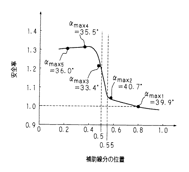
図6に示すように、B形車輪10Bも同様に、図示しない車軸が嵌挿されるボス部11Bから、順に外側へかけてボス部フィレット12B、板部13B、リム部フィレット14B、リム部15B、及び車輪内輪側に突設されるフランジ16Bから、B形車輪10Bが形成される。B形車輪10Bは、A形車輪10Aとは逆に、リム部15Bがボス部11Bに対して内輪側に偏心している形状と定義され、また、JIS規格5402−1989によれば、各部位の長さは下記の表2に示す如く規定されている。
【0006】
【表2】
新幹線等に用いられるC形車輪10Cの径方向の断面形状も、図7に示すように他の車輪と同じく図示しない車軸が嵌挿されるボス部11Cから、順に外側へかけてボス部フィレット12C、板部13C、リム部フィレット14C、リム部15C、及び車輪内輪側に突設されるフランジ16Cから、C形車輪10Cが形成される。C形車輪10Cは、A形車輪10A及びB形車輪10Bとは異なり、リム部15Cがボス部11Cに対して内輪側及び外輪側いずれにも偏心していない形状と定義され、また、JIS規格5402−1989によれば、各部位の長さは下記の表3に示す如く規定されている。
【0008】
【表3】
【特許文献1】
特開平10−29401号公報
【0010】
【発明が解決しようとする課題】
しかしながら、例えば、表1に示すように従来の車輪は板部の板厚がリム側でt1=18mm、ボス側でt2=22mm〜26mmと厚いため、車輪の軽量化による鉄道の高速化及び省エネルギー化を達成することは困難であった。また、軽量化を図るべく、板厚を薄くした場合、耐割損性が増加し安全率が低下するという問題があった。レールからの反力により発生する応力(機械的応力)が増加した場合、耐割損性が増加し、安全率が低下する。本願出願人は安全率を維持または向上させつつ、板部の板厚を薄くし、軽量化を図ることが可能な車輪を開発すべく鋭意研究を重ねた結果、A形車輪の場合、板部の径方向の断面形状を規定する2つの曲線のうち、内輪側の曲線形状を特定の形状とすることにより、板部の板厚を薄くしつつも、安全率を向上することが可能であることを知見した。
【0011】
一方、B形車輪の場合、板部の径方向の断面形状を規定する2つの曲線のうち、外輪側の曲線形状を特定の形状とすることにより、A形車輪と同様に板部の板厚を薄くしつつも、安全率を向上することが可能であることをも知見した。
【0012】
本発明は斯かる知見に鑑みてなされたものであり、その目的とするところは、板部の径方向の断面形状を規定する2つの曲線のうち、A形車輪の場合は、内輪側の曲線形状を特定の形状とすることにより、またB形車輪の場合は、外輪側の曲線形状を特定の形状とすることにより、板厚を薄くした場合であっても、従来と同等の安全率を維持することが可能な鉄道用車輪を提供することにある。
【0013】
【課題を解決するための手段】
第1発明に係る鉄道用車輪は、内側から外側にかけてボス部、ボス部フィレット、板部、リム部フィレット、リム部、及び、フランジを有し、前記リム部が前記ボス部に対して外輪側に偏心している鉄道用車輪において、前記ボス部フィレット、板部及びリム部フィレットの径方向の断面形状を規定する2つの曲線のうち、内輪側の曲線の接線と、前記ボス部に挿嵌される車軸の軸心に対する法線とのなす角の最大値をとる前記内輪側板部の曲線上の点が、前記2つの曲線と前記ボス部との交点により規定されるボス側線分、及び、前記2つの曲線と前記リム部との交点により規定されるリム側線分から等距離の位置に形成される補助線分が前記内輪側の曲線と交差する点よりもボス側に位置することを特徴とする。
【0014】
第2発明に係る鉄道用車輪は、内側から外側にかけてボス部、ボス部フィレット、板部、リム部フィレット、リム部、及び、フランジを有し、前記リム部が前記ボス部に対して内輪側に偏心している鉄道用車輪において、前記ボス部フィレット、板部及びリム部フィレットの径方向の断面形状を規定する2つの曲線のうち、外輪側の曲線の接線と、前記ボス部に挿嵌される車軸の軸心に対する法線とのなす角の最大値をとる前記外輪側板部の曲線上の点が、前記2つの曲線と前記ボス部との交点により規定されるボス側線分、及び、前記2つの曲線と前記リム部との交点により規定されるリム側線分から等距離の位置に形成される補助線分が前記外輪側の曲線と交差する点よりもボス側に位置することを特徴とする。
【0015】
第3発明に係る鉄道用車輪は、内側から外側にかけてボス部、ボス部フィレット、板部、リム部フィレット、リム部、及び、フランジを有し、前記リム部が前記ボス部に対して外輪側に偏心している鉄道用車輪において、前記ボス部フィレット、板部及びリム部フィレットの径方向の断面形状を規定する2つの曲線のうち、内輪側の曲線の接線と、前記ボス部に挿嵌される車軸の軸心に対する法線とのなす角の最大値をとる前記内輪側板部の曲線上の点が、前記2つの曲線と前記ボス部との交点により規定されるボス側線分からと、前記2つの曲線と前記リム部との交点により規定されるリム側線分からとの距離比が0.55対0.45の位置に形成される補助線分が前記内輪側の曲線と交差する点よりもボス側に位置することを特徴とする。
【0016】
第4発明にかかる鉄道用車輪は、内側から外側にかけてボス部、ボス部フィレット、板部、リム部フィレット、リム部、及び、フランジを有し、前記リム部が前記ボス部に対して内輪側に偏心している鉄道用車輪において、前記ボス部フィレット、板部及びリム部フィレットの径方向の断面形状を規定する2つの曲線のうち、外輪側の曲線の接線と、前記ボス部に挿嵌される車軸の軸心に対する法線とのなす角の最大値をとる前記外輪側板部の曲線上の点が、前記2つの曲線と前記ボス部との交点により規定されるボス側線分からと、前記2つの曲線と前記リム部との交点により規定されるリム側線分からとの距離比が0.55対0.45の位置に形成される補助線分が前記外輪側の曲線と交差する点よりもボス側に位置することを特徴とする。
【0017】
第1及び第3発明にあっては、リム部がボス部に対して、外輪側に偏心しているA形車輪の場合、ボス部フィレット、板部及びリム部フィレットの径方向の断面形状を規定する2つの曲線のうち、内輪側の曲線について着目する。曲線は、2つの曲線とボス部との交点により規定されるボス側線分から、2つの曲線とリム部との交点により規定されるリム側線分に至る。内輪側の曲線の接線と、ボス部に挿嵌される車軸の軸心に対する法線とのなす角を計測し、その最大値をとる内輪側板部の曲線上の点が、ボス側線分及びリム側線分から等距離の位置に形成される補助線分が内輪側の曲線と交差する点よりもボス側に位置するよう決定する。また、安全率を従来の車輪以上とするためには、後述する実験により、内輪側の曲線の接線と、ボス側線分の法線とのなす角の最大値をとる内輪側板部の曲線上の点が、ボス側線分からと、リム側線分からとの距離比が0.55対0.45の位置に形成される補助線分が内輪側の曲線と交差する点よりもボス側に位置するようにすれば良い。鉄道用車輪の板部形状をかかる構成とすることで、安全率のさらなる向上、ひいては板部の板厚を薄くし、軽量化を図りつつも従来と同様またはそれ以上の安全率を確保することが可能となる。
【0018】
第2及び第4発明にあっては、リム部がボス部に対して、内輪側に偏心しているB形車輪の場合、ボス部フィレット、板部及びリム部フィレットの径方向の断面形状を規定する2つの曲線のうち、外輪側の曲線について着目する。同様に、外輪側の曲線の接線と、ボス部に挿嵌される車軸の軸心に対する法線とのなす角を計測し、その最大値をとる外輪側の曲線上の点が、ボス側線分及びリム側線分から等距離の位置に形成される補助線分が外輪側の曲線と交差する点よりもボス側に位置するよう決定する。または、安全率を従来の車輪以上とするためには、後述する実験により、外輪側の曲線の接線と、ボス側線分の法線とのなす角の最大値をとる外輪側板部の曲線上の点が、ボス側線分からと、リム側線分からとの距離比が0.55対0.45の位置に形成される補助線分が外輪側の曲線と交差する点よりもボス側に位置すれば良い。このように、リム部の偏心方向と逆方向の板部曲線の形状をかかる形状とすることで、板部の板厚を薄くし、軽量化を図りつつも従来と同様またはそれ以上の安全率を確保でき、さらに鉄道車両の高速化及び省エネルギー化を図ることが可能となる。
【0019】
【発明の実施の形態】
以下本発明を実施の形態を示す図面に基づいて詳述する。
実施の形態1
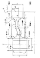
図1はA形車輪1A(場合により、車輪1で代表する)の径方向の断面形状を示す断面図である。A形車輪1Aは、内側から外側にかけてボス部11,ボス部フィレット12,板部13,リム部フィレット14,リム部15,及びフランジ16からなり、リム部15がボス部11に対して外輪側に偏心している。図示しない車軸が径方向に対して垂直に嵌挿されるボス部11には、板部13に至るボス部フィレット12が形成されており、車輪厚はボス部フィレット12を経由して、ボス部11のボス高さHから板部13の板厚t2(ボス側)にまで変化する。なお、各部位の長さは表1に示すとおりである。
【0020】
板部13の一端は上述したボス部フィレット12と接合しており、一方板部13の他端はリム部フィレット14と接合している。板部13の径方向の断面形状は曲線st、及び曲線uw、並びに曲線st・曲線uwとボス部フィレット12とのそれぞれの交点s、uにより規定される線分su、及び、曲線st・曲線uwとリム部フィレット14とのそれぞれの交点t、wにより規定される線分twにより構成される。また、ボス部フィレット、板部及びリム部フィレットの径方向の断面形状を規定する2つの曲線は図1に示すように曲線ab及び曲線cdからなる。点aは内輪側の曲線abとボス部11との交点であり、点cは外輪側の曲線cdとボス部11との交点である。以下では、線分acをボス側線分という。同様に、点bは内輪側の曲線abとリム部15との交点であり、点dは外輪側の曲線cdとリム部15との交点である。以下では、線分bdをリム側線分という。板部13はリム部フィレット14を介してリム部15に接合されており、車輪厚はリム部フィレット14を経由している間に板部13の板厚t1(リム側)からリム幅Bにまで拡大する。また、リム部15の内輪側先端にはフランジが突設されている。
【0021】
A形車輪1Aにおいては、ボス部フィレット12,板部13及びリム部フィレット14の断面形状を規定する2つの曲線ab及び曲線cdのうち、内輪側の曲線ab、特に曲線stについて着目する。曲線ab上の任意の点における接線Lと、ボス部に挿嵌される図示しない車軸の軸心Zに対する法線hとのなす角をαと定義する。本発明に係る車輪は、好ましくはαの最大角αmaxをとる内輪側板部の曲線st上の点が、ボス側線分ac及びリム側線分bdから等距離の位置に形成され、ボス側線分ac及びリム側線分bdに平行な補助線分が、内輪側の曲線abと交差する点eよりもボス側に位置するようにすれば良い。つまり、点sから補助線分と曲線abとの交点である点eとの間のいずれかの位置に、最大角αmaxが形成されるよう板部13の形状を設計する。若しくは、αの最大角αmaxをとる内輪側板部の曲線st上の点が、ボス側線分acからと、リム側線分bdからとの距離比が0.55対0.45となる位置に形成され、ボス側線分ac及びリム側線分bdに平行な補助線分が、内輪側の曲線abと交差する点e’よりもボス側に位置するようにすれば良い。つまり、点sから補助線分と曲線abとの交点である点e’との間のいずれかの位置に、最大角αmaxが形成されるよう板部13の形状を設計する。すなわち、外輪側に偏心しているA形車輪1Aにおいては、対向する内輪側の曲線stのうち、ボス部11側の接線Lと法線hとのなす角度αが最大となるよう、板部13を設計することで、安全率を向上させることが可能となる。
【0022】
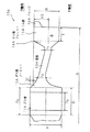
図2はB形車輪1Bの径方向の断面形状を示す断面図である。B形車輪1Bも同様に、内側から外側にかけてボス部11,ボス部フィレット12,板部13,リム部フィレット14,リム部15,及びフランジ16からなり、リム部15がボス部11に対して内輪側に偏心している。
【0023】
B形車輪1Bにおいては、ボス部フィレット12,板部13、及びリム部フィレット14の断面形状を規定する2つの曲線ab及び曲線cdのうち、外輪側の曲線cd、特に曲線uwについて着目する。曲線cd上の任意の点における接線Lと、軸心Zに対する法線hとのなす角をαと定義する。本発明に係る車輪は、好ましくはαの最大角αmaxをとる外輪側板部の曲線uw上の点が、ボス側線分ac及びリム側線分bdから等距離の位置に形成され、ボス側線分ac及びリム側線分bdに平行な補助線分が、外輪側の曲線cdと交差する点fよりもボス側に位置するようにすれば良い。つまり、点uから補助線分と曲線cdとの交点である点fとの間のいずれかの位置に、最大角αmaxが形成されるよう板部13の形状を設計する。若しくは、αの最大角αmaxをとる外部側板部の曲線cd上の点が、ボス側線分acからと、リム側線分bdからとの距離比が0.55対0.45となる位置に形成され、ボス側線分ac及びリム側線分bdに平行な補助線分が、外輪側の曲線cdと交差する点f’よりもボス側に位置するようにすれば良い。つまり、点sから補助線分と曲線cdとの交点である点f’との間のいずれかの位置に、最大角αmaxが形成されるよう板部13の形状を設計する。すなわち、内輪側に偏心しているB形車輪1Bにおいては、対向する外輪側の曲線uwのうち、ボス部11側の接線Lと法線hとのなす角度αが最大となるよう、板部13を設計することで、安全率を向上させることが可能となる。
【0024】
続いて、最大角αmaxをとる曲線上の位置を変化させて安全率がどのように変化するか実験を行った。なお、実験に当たってはA形車輪1Aのうち表1に示すA86Eを用い、板部13の形状をそれぞれ変化させた車輪1を対象にFEM(Finite Element Method)解析を実施し、垂直圧及び横圧が負荷された場合の板部13の発生応力と、垂直圧及び背圧が負荷された場合の発生応力を求め、各板部形状の耐割損性(安全率)について評価した。
【0025】
なお以下に、垂直圧、横圧、及び背圧について説明しておく。図3は機械的応力の概念を説明する模式図である。機械的応力には図3(a)及び(b)に示すように、垂直圧P1、横圧P2、及び背圧P3が存在する。直線通過時においては、輪重により、リム部15とレールRとの接合面である車輪踏面QにはレールRから垂直圧P1が負荷される。曲線通過時においては、レールRからフランジ16に軌道内側から横圧P2が負荷される。さらに、脱線防止用のガイドレールP又は図示しないポイントにより、フランジ16に軌道外側から背圧P3が負荷される。
【0026】
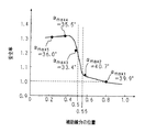
図4は最大角αmaxをとる点の位置を変化させた場合の、当該車輪の安全率の推移を示す特性図ある。縦軸は安全率を示し、従来の車輪の安全率を1.0として評価している。横軸は補助線分の位置を示し、0をボス側線分acと同じ位置、0.5をボス側線分及びリム側線分bdから等距離の位置、1をリム側線分bdと同じ位置としている。ここで、曲線ab上の内曲線st上の点における接線Lと法線hとがなす角αが最大値αmaxとなるとなる点を、位置を変えつつその各車輪における最小の安全率を車輪板部全体のFEM解析により求めた。解析にあっては試料1乃至5を用意した。試料1は従来の車輪であり、試料1及び2を除く試料3乃至5は本発明に係るA形車輪1Aである。なお、各試料の最大角αmaxは、αmax1=39.9°(試料1)、αmax2=40.7°(試料2)、αmax3=33.4°(試料3)、αmax4=35.5°(試料4)、αmax5=36.0°(試料5)とした。
【0027】
解析した結果、試料3乃至5に示すように0から0.55までの間で、最大値αmaxをとる場合、安全率が高いことが理解できる。特に0.55から0.5にかけて安全率の増加傾向が強まり、また0.5以下ではボスの内径、輪重等の諸条件が変わった場合でも高い安全率を確保できることが確認できた。一方で、試料2の如く0.55を超える場合、従来の試料1に係る車輪と安全率はそれほど相違しないことが理解できる。このように最大値αmaxをとる点を特定の位置(点s〜点eまたは点e’)に決定することで、安全率の向上を図ることが可能となる。なお、B形車輪についても同様の結果が得られたので詳細な説明は省略する。また、上述した試料1乃至5は全て板部13の板厚t1(リム側)を18mm、板厚t2(ボス側)を22mmとして、安全率の変化を検討したが、安全率が1.0以上となるように板厚を適宜変化させるようにしても良い。この場合、リム外径Dに対して、板部13の板厚が1.2%〜2.4%の範囲内にある場合、安全率1.0以上となることが確認できた。例えば、リム外径Dが860mmの車輪の場合、板厚は10.32mm〜20.64mmの範囲内であれば、安全率1.0以上を確保できる。これにより、安全率を確保しつつも、板部13の薄型化を図ることができる。
【0028】
【発明の効果】
以上詳述した如く、第1及び第3発明にあっては、リム部がボス部に対して、外輪側に偏心しているA形車輪の場合、ボス部フィレット、板部及びリム部フィレットの径方向の断面形状を規定する2つの曲線のうち、内輪側の曲線の接線と、ボス側線分の法線とのなす角を計測し、その最大値をとる内輪側板部の曲線上の点が、ボス側線分及びリム側線分から等距離の位置に形成される補助線分が内輪側の曲線と交差する点よりもボス側に位置するように設計する。または、ボス側線分からと、リム側線分からとの距離比が0.55対0.45の位置に形成される補助線分が内輪側の曲線と交差する点よりもボス側に位置するよう設計する。このように鉄道用車輪の板部形状をかかる構成とすることで、安全率のさらなる向上、ひいては板部の板厚を薄くし、軽量化を図りつつも従来と同様またはそれ以上の安全率を確保することが可能となる。
【0029】
第2及び第4発明にあっては、リム部がボス部に対して、内輪側に偏心しているB形車輪の場合、ボス部フィレット、板部及びリム部フィレットの径方向の断面形状を規定する2つの曲線のうち、外輪側の曲線の接線と、ボス側線分の法線とのなす角を計測し、その最大値をとる外輪側の曲線上の点が、ボス側線分及びリム側線分から等距離の位置に形成される補助線分が外輪側の曲線と交差する点よりもボス側に位置するよう設計する。または、ボス側線分からと、リム側線分からとの距離比が0.55対0.45の位置に形成される補助線分が内輪側の曲線と交差する点よりもボス側に位置するよう設計する。このように、リム部の偏心方向と逆方向の板部曲線の形状をかかる形状とすることで、板部の板厚を薄くし、軽量化を図りつつも従来と同様またはそれ以上の安全率を確保でき、さらに鉄道車両の高速化及び省エネルギー化を図ることが可能となる等、本発明は優れた効果を奏し得る。
【図面の簡単な説明】
【図1】A形車輪の径方向の断面形状を示す断面図である。
【図2】B形車輪の径方向の断面形状を示す断面図である。
【図3】機械的応力の概念を説明する模式図である。
【図4】最大角αmaxをとる点の位置を変化させた場合の、当該車輪の安全率の推移を示す特性図ある。
【図5】A形車輪の径方向の断面形状を示す断面図である。
【図6】B形車輪の径方向の断面形状を示す断面図である。
【図7】C形車輪の径方向の断面形状を示す断面図である。
【符号の説明】
1 車輪
1A A形車輪
1B B形車輪
11 ボス部
12 ボス部フィレット
13 板部
14 リム部フィレット
15 リム部
16 フランジ
ab 曲線
cd 曲線
ac ボス側線分
bd リム側線分[0001]
TECHNICAL FIELD OF THE INVENTION
A type or B type comprising a boss portion, a boss portion fillet, a plate portion, a rim portion fillet, a rim portion and a flange from the inside to the outside, wherein the rim portion is eccentric to the outer ring side or the inner ring side with respect to the boss portion. In particular, the present invention relates to a railway wheel having an optimized shape of a plate portion between a boss portion fillet and a rim portion fillet.
[0002]
[Prior art]
2. Description of the Related Art From the viewpoint of increasing the speed of railway vehicles and saving energy, it is desired to reduce the weight of railway wheels (hereinafter referred to as wheels). Although the weight of the wheel can be reduced by reducing the plate thickness of the plate portion, the reduction in the plate thickness lowers the breakage resistance. Therefore, it is necessary to reduce the weight of the wheels while maintaining the breakage resistance.
[0003]
Conventional railway wheels are designed in accordance with, for example, Japanese Industrial Standard JIS E5402-1989. In such a standard, three types of railway wheels, namely A type, B type and C type, are specified. 5 is a cross-sectional view showing a radial cross-sectional shape of an A-type wheel, FIG. 6 is a cross-sectional view showing a radial cross-sectional shape of a B-type wheel, and FIG. 7 is a cross-sectional view showing a radial cross-sectional shape of a C-type wheel. It is. From the boss portion 11A into which the axle (not shown) is inserted, the boss portion fillet 12A, the plate portion 13A, the rim portion fillet 14A, the rim portion 15A, and the flange 16A protruding from the inner wheel side of the wheel are formed in an A-shape. A
[0004]
[Table 1]
As shown in FIG. 6, the B-
[0006]
[Table 2]
As shown in FIG. 7, the C-
[0008]
[Table 3]
[Patent Document 1]
JP-A-10-29401
[Problems to be solved by the invention]
However, for example, thicker and t 2 = 22mm~26mm at t 1 = 18 mm, the boss-side plate thickness of the conventional wheel plate portion as shown in Table 1 is the rim side, faster railway by weight of the wheel And it was difficult to achieve energy saving. Further, when the sheet thickness is reduced in order to reduce the weight, there is a problem that the breakage resistance increases and the safety factor decreases. When the stress (mechanical stress) generated by the reaction force from the rail increases, the breakage resistance increases and the safety factor decreases. The applicant of the present application has conducted intensive studies to develop a wheel capable of reducing the thickness of the plate portion and reducing the weight while maintaining or improving the safety factor. By making the curve shape on the inner ring side a specific shape among the two curves defining the cross-sectional shape in the radial direction, it is possible to improve the safety factor while reducing the thickness of the plate portion. I found that.
[0011]
On the other hand, in the case of a B-type wheel, the thickness of the plate portion is made similar to that of the A-type wheel by making the curve shape on the outer ring side a specific shape among the two curves defining the radial cross-sectional shape of the plate portion. It was also found that it was possible to improve the safety factor while reducing the thickness.
[0012]
The present invention has been made in view of such knowledge, and an object of the present invention is to provide an A-shaped wheel, among two curves defining a cross-sectional shape in a radial direction of a plate portion, a curve on an inner wheel side. By setting the shape to a specific shape, and in the case of a B-type wheel, by setting the curved shape on the outer ring side to a specific shape, even if the plate thickness is reduced, the same safety factor as before can be achieved. It is to provide a railway wheel that can be maintained.
[0013]
[Means for Solving the Problems]
The railway wheel according to the first invention has a boss portion, a boss portion fillet, a plate portion, a rim portion fillet, a rim portion, and a flange from the inside to the outside, and the rim portion is on the outer ring side with respect to the boss portion. Of the two curves that define the radial cross-sectional shape of the boss portion fillet, the plate portion, and the rim portion fillet, the rail wheel is eccentric to the tangent to the curve on the inner ring side, and is fitted to the boss portion. A point on the curve of the inner ring side plate portion that takes the maximum value of the angle formed by the normal to the axis of the axle, the boss side line segment defined by the intersection of the two curves and the boss portion, and An auxiliary line segment formed at a position equidistant from a rim side line segment defined by an intersection of the two curves and the rim portion is located closer to the boss than a point intersecting the inner ring side curve. .
[0014]
The railway wheel according to the second invention has a boss portion, a boss portion fillet, a plate portion, a rim portion fillet, a rim portion, and a flange from inside to outside, and the rim portion is on the inner wheel side with respect to the boss portion. Of the two curves defining the radial cross-sectional shape of the boss portion fillet, the plate portion, and the rim portion fillet, the rail wheel is eccentric to the tangent line of the curve on the outer ring side, and is fitted to the boss portion. A point on the curve of the outer ring side plate portion that takes the maximum value of the angle formed by the normal to the axis of the axle, the boss side line segment defined by the intersection of the two curves and the boss portion, and An auxiliary line segment formed at a position equidistant from a rim side line segment defined by an intersection between the two curves and the rim portion is located closer to the boss than a point intersecting the outer ring side curve. .
[0015]
The railway wheel according to the third invention has a boss portion, a boss portion fillet, a plate portion, a rim portion fillet, a rim portion, and a flange from the inside to the outside, and the rim portion is on the outer ring side with respect to the boss portion. Of the two curves that define the radial cross-sectional shape of the boss portion fillet, the plate portion, and the rim portion fillet, the rail wheel is eccentric to the tangent to the curve on the inner ring side, and is fitted to the boss portion. The point on the curve of the inner ring side plate portion, which takes the maximum value of the angle formed by the normal to the axis of the axle, is determined from the boss side line segment defined by the intersection of the two curves and the boss portion. The auxiliary line segment formed at a distance ratio of 0.55 to 0.45 from the rim side line segment defined by the intersection between the two curves and the rim portion is more boss than the point where the auxiliary line segment intersects the inner ring side curve. Located on the side
[0016]
The railway wheel according to the fourth invention has a boss, a boss fillet, a plate, a rim fillet, a rim, and a flange from the inside to the outside, and the rim is on the inner wheel side with respect to the boss. Of the two curves defining the radial cross-sectional shape of the boss portion fillet, the plate portion, and the rim portion fillet, the rail wheel is eccentric to the tangent line of the curve on the outer ring side, and is fitted to the boss portion. The point on the curve of the outer ring side plate portion, which takes the maximum value of the angle formed by the normal to the axis of the axle, is determined from the boss side line segment defined by the intersection of the two curves and the boss portion. The auxiliary line segment formed at a distance ratio of 0.55 to 0.45 from the rim side line segment defined by the intersection between the two curves and the rim portion is more boss than the point where the auxiliary line segment intersects the outer ring side curve. Located on the side .
[0017]
In the first and third inventions, in the case of an A-shaped wheel in which the rim portion is eccentric to the outer ring side with respect to the boss portion, the radial cross-sectional shapes of the boss portion fillet, the plate portion, and the rim portion fillet are defined. Of the two curves to be performed, attention is paid to the curve on the inner ring side. The curve ranges from a boss side line segment defined by the intersection of the two curves and the boss portion to a rim side line segment defined by the intersection of the two curves and the rim portion. Measure the angle between the tangent of the curve on the inner ring side and the normal to the axis of the axle that is inserted into the boss, and the point on the curve of the inner ring side plate that takes the maximum value is the boss side line and the rim. It is determined that the auxiliary line segment formed at a position equidistant from the side line segment is located closer to the boss than the point where it intersects the curve on the inner wheel side. In addition, in order to make the safety factor equal to or higher than that of the conventional wheel, an experiment described later shows that the tangent of the curve on the inner ring side and the curve of the inner ring side plate portion that takes the maximum value of the angle formed by the normal to the boss side line are calculated. The point is such that the auxiliary line segment formed at a distance ratio of 0.55 to 0.45 from the boss side line segment to the rim side line segment is located closer to the boss than the point where it intersects the curve on the inner ring side. Just do it. By adopting such a configuration of the plate part of the railway wheel, the safety factor is further improved, and as a result, the thickness of the plate part is reduced, and the same or higher safety factor is ensured while reducing the weight. Becomes possible.
[0018]
In the second and fourth inventions, in the case of a B-type wheel in which the rim portion is eccentric to the inner ring side with respect to the boss portion, the radial cross-sectional shapes of the boss portion fillet, the plate portion, and the rim portion fillet are defined. Of the two curves to be performed, attention is paid to the curve on the outer ring side. Similarly, the angle between the tangent of the curve on the outer ring side and the normal to the axis of the axle inserted into the boss is measured, and the point on the curve on the outer ring that takes the maximum value is the line segment on the boss side. In addition, it is determined that the auxiliary line segment formed at a position equidistant from the rim side line segment is located closer to the boss than the point where the auxiliary line segment intersects the curve on the outer ring side. Or, in order to make the safety factor equal to or higher than that of the conventional wheel, it is necessary to determine the maximum value of the angle between the tangent of the curve on the outer ring side and the normal to the boss side line by the experiment described later. The point may be located closer to the boss than the point where the auxiliary line formed at a distance ratio of 0.55 to 0.45 between the boss side line and the rim side line intersects the outer ring side curve. . In this way, by making the shape of the plate portion curve in the direction opposite to the eccentric direction of the rim portion into such a shape, the thickness of the plate portion is reduced, and the safety factor is equal to or higher than the conventional one while reducing the weight. , And it is possible to further increase the speed and energy saving of the railway vehicle.
[0019]
BEST MODE FOR CARRYING OUT THE INVENTION
Hereinafter, the present invention will be described in detail with reference to the drawings showing embodiments.
FIG. 1 is a cross-sectional view showing a radial cross-sectional shape of an A-shaped wheel 1A (represented by the
[0020]
One end of the plate 13 is joined to the boss fillet 12 described above, while the other end of the plate 13 is joined to the rim fillet 14. The cross-sectional shape in the radial direction of the plate portion 13 is a curve st and a curve uw, and a line segment su and a curve st and a curve defined by respective intersections s and u between the curve st and the curve uw and the boss portion fillet 12. It is constituted by a line segment tw defined by respective intersections t and w between uw and the rim portion fillet 14. Further, two curves defining the radial cross-sectional shapes of the boss portion fillet, the plate portion, and the rim portion fillet include a curve ab and a curve cd as shown in FIG. The point a is the intersection between the curve ab on the inner ring side and the
[0021]
In the A-type wheel 1A, of the two curves ab and cd defining the cross-sectional shapes of the boss portion fillet 12, the plate portion 13, and the rim portion fillet 14, attention is paid to the curve ab on the inner wheel side, particularly the curve st. An angle between a tangent L at an arbitrary point on the curve ab and a normal h to the axis Z of the axle (not shown) inserted into the boss portion is defined as α. In the wheel according to the present invention, preferably, a point on the curve st of the inner ring side plate portion having the maximum angle α max of α is formed at a position equidistant from the boss side line ac and the rim side line bd, and the boss side line ac The auxiliary line segment parallel to the rim side line segment bd may be positioned closer to the boss than the point e that intersects the curve ab on the inner ring side. That is, the shape of the plate portion 13 is designed so that the maximum angle α max is formed at any position between the point s and the point e which is the intersection of the auxiliary line segment and the curve ab. Alternatively, a point on the curve st of the inner ring side plate portion having the maximum angle α max of α is formed at a position where the distance ratio between the boss side line segment ac and the rim side line segment bd is 0.55 to 0.45. It is sufficient that the auxiliary line segment parallel to the boss side line segment ac and the rim side line segment bd is positioned closer to the boss than the point e ′ that intersects the curve ab on the inner ring side. That is, the shape of the plate portion 13 is designed so that the maximum angle α max is formed at any position between the point s and the point e ′ which is the intersection of the auxiliary line segment and the curve ab. That is, in the A-shaped wheel 1A eccentric to the outer ring side, the plate portion 13 is formed so that the angle α between the tangent line L on the
[0022]
FIG. 2 is a cross-sectional view showing a cross-sectional shape in the radial direction of the B-
[0023]
In the B-shaped
[0024]
Subsequently, an experiment was conducted to see how the safety factor changes by changing the position on the curve that takes the maximum angle α max . In the experiment, the A86E shown in Table 1 among the A-shaped wheels 1A was used, and FEM (Finite Element Method) analysis was performed on the
[0025]
Hereinafter, the vertical pressure, the lateral pressure, and the back pressure will be described. FIG. 3 is a schematic diagram illustrating the concept of mechanical stress. As shown in FIGS. 3A and 3B, the mechanical stress includes a vertical pressure P 1 , a lateral pressure P 2 , and a back pressure P 3 . During straight pass, the wheel load, the wheel tread Q is a bonding surface of the
[0026]
FIG. 4 is a characteristic diagram showing a change in the safety factor of the wheel when the position of the point having the maximum angle α max is changed. The vertical axis indicates the safety factor, and the safety factor of the conventional wheel is evaluated as 1.0. The horizontal axis indicates the position of the auxiliary line segment. 0 is the same position as the boss side line ac, 0.5 is the position equidistant from the boss side line and the rim side line bd, and 1 is the same position as the rim side line bd. . Here, the point at which the angle α between the tangent L and the normal h at the point on the inner curve st on the curve ab becomes the maximum value α max is determined by changing the minimum safety factor of each wheel while changing the position. It was determined by FEM analysis of the entire plate portion.
[0027]
As a result of the analysis, it can be understood that the safety factor is high when the maximum value α max is taken from 0 to 0.55 as shown in
[0028]
【The invention's effect】
As described in detail above, in the first and third aspects of the present invention, in the case of an A-shaped wheel in which the rim portion is eccentric to the outer ring side with respect to the boss portion, the diameter of the boss portion fillet, the plate portion, and the rim portion fillet Of the two curves that define the cross-sectional shape in the direction, the angle between the tangent to the curve on the inner ring side and the normal to the boss side line is measured, and the point on the curve of the inner ring side plate that takes the maximum value is: An auxiliary line segment formed at a position equidistant from the boss side line segment and the rim side line segment is designed to be located closer to the boss than a point intersecting the curve on the inner ring side. Alternatively, the auxiliary line segment formed at a distance ratio of 0.55 to 0.45 from the boss side line segment to the rim side line segment is designed so as to be located closer to the boss than a point where it intersects the curve on the inner ring side. . By adopting such a configuration of the plate portion of the railway wheel in this way, the safety factor is further improved, and thus the plate portion is made thinner, and the safety factor is equal to or higher than the conventional one while reducing the weight. It is possible to secure.
[0029]
In the second and fourth inventions, in the case of a B-type wheel in which the rim portion is eccentric to the inner ring side with respect to the boss portion, the radial cross-sectional shapes of the boss portion fillet, the plate portion, and the rim portion fillet are defined. Of the two curves, the angle between the tangent of the outer ring side curve and the normal to the boss side line is measured, and the point on the outer ring side curve that takes its maximum value is calculated from the boss side line and the rim side line. The auxiliary line segment formed at the equidistant position is designed to be located on the boss side with respect to the intersection with the curve on the outer ring side. Alternatively, the auxiliary line segment formed at a distance ratio of 0.55 to 0.45 from the boss side line segment to the rim side line segment is located closer to the boss than a point where the auxiliary line intersects the curve on the inner ring side. . In this way, by making the shape of the plate portion curve in the direction opposite to the eccentric direction of the rim portion into a shape, the thickness of the plate portion is reduced, and the safety factor is equal to or higher than the conventional one while reducing the weight. Thus, the present invention can provide excellent effects such as ensuring high speed and energy saving of railway vehicles.
[Brief description of the drawings]
FIG. 1 is a cross-sectional view showing a radial cross-sectional shape of an A-type wheel.
FIG. 2 is a cross-sectional view illustrating a radial cross-sectional shape of a B-type wheel.
FIG. 3 is a schematic diagram illustrating the concept of mechanical stress.
FIG. 4 is a characteristic diagram showing a change in the safety factor of the wheel when the position of a point having a maximum angle α max is changed.
FIG. 5 is a cross-sectional view showing a radial cross-sectional shape of an A-type wheel.
FIG. 6 is a sectional view showing a radial cross-sectional shape of a B-type wheel.
FIG. 7 is a cross-sectional view showing a radial cross-sectional shape of a C-type wheel.
[Explanation of symbols]
DESCRIPTION OF
Claims (4)
前記ボス部フィレット、板部及びリム部フィレットの径方向の断面形状を規定する2つの曲線のうち、内輪側の曲線の接線と、前記ボス部に挿嵌される車軸の軸心に対する法線とのなす角の最大値をとる前記内輪側板部の曲線上の点が、
前記2つの曲線と前記ボス部との交点により規定されるボス側線分、及び、前記2つの曲線と前記リム部との交点により規定されるリム側線分から等距離の位置に形成される補助線分が前記内輪側の曲線と交差する点よりもボス側に位置する
ことを特徴とする鉄道用車輪。From the inside to the outside, a boss portion, a boss portion fillet, a plate portion, a rim portion fillet, a rim portion, and a railway wheel having the flange, wherein the rim portion is eccentric to the outer ring side with respect to the boss portion,
Of the two curves defining the radial cross-sectional shape of the boss portion fillet, the plate portion, and the rim portion fillet, a tangent to an inner ring side curve and a normal to an axis of an axle inserted into the boss portion. The point on the curve of the inner ring side plate that takes the maximum value of the angle
A boss side line segment defined by the intersection of the two curves and the boss portion, and an auxiliary line segment formed at a position equidistant from the rim side line segment defined by the intersection of the two curves and the rim portion Are located closer to the boss than to the point where they intersect the curve on the inner wheel side.
前記ボス部フィレット、板部及びリム部フィレットの径方向の断面形状を規定する2つの曲線のうち、外輪側の曲線の接線と、前記ボス部に挿嵌される車軸の軸心に対する法線とのなす角の最大値をとる前記外輪側板部の曲線上の点が、
前記2つの曲線と前記ボス部との交点により規定されるボス側線分、及び、前記2つの曲線と前記リム部との交点により規定されるリム側線分から等距離の位置に形成される補助線分が前記外輪側の曲線と交差する点よりもボス側に位置する
ことを特徴とする鉄道用車輪。From the inside to the outside, a boss portion, a boss portion fillet, a plate portion, a rim portion fillet, a rim portion, and a railway wheel having a flange, wherein the rim portion is eccentric to the inner ring side with respect to the boss portion,
Of the two curves that define the radial cross-sectional shape of the boss fillet, the plate portion, and the rim fillet, a tangent to an outer ring side curve and a normal to an axis of an axle inserted into the boss. The point on the curve of the outer ring side plate that takes the maximum value of the angle
A boss side line segment defined by the intersection of the two curves and the boss portion, and an auxiliary line segment formed at a position equidistant from the rim side line segment defined by the intersection of the two curves and the rim portion Is located closer to the boss than a point that intersects the curve on the outer ring side.
前記ボス部フィレット、板部及びリム部フィレットの径方向の断面形状を規定する2つの曲線のうち、内輪側の曲線の接線と、前記ボス部に挿嵌される車軸の軸心に対する法線とのなす角の最大値をとる前記内輪側板部の曲線上の点が、
前記2つの曲線と前記ボス部との交点により規定されるボス側線分からと、前記2つの曲線と前記リム部との交点により規定されるリム側線分からとの距離比が0.55対0.45の位置に形成される補助線分が前記内輪側の曲線と交差する点よりもボス側に位置する
ことを特徴とする鉄道用車輪。From the inside to the outside, a boss portion, a boss portion fillet, a plate portion, a rim portion fillet, a rim portion, and a railway wheel having the flange, wherein the rim portion is eccentric to the outer ring side with respect to the boss portion,
Of the two curves defining the radial cross-sectional shape of the boss portion fillet, the plate portion, and the rim portion fillet, a tangent to an inner ring side curve and a normal to an axis of an axle inserted into the boss portion. The point on the curve of the inner ring side plate that takes the maximum value of the angle
The distance ratio between the boss side line segment defined by the intersection of the two curves and the boss portion and the rim side line segment defined by the intersection point of the two curves and the rim portion is 0.55 to 0.45. A railway wheel, characterized in that the auxiliary line segment formed at the position (1) is located closer to the boss than a point where the auxiliary line segment intersects the curve on the inner wheel side.
前記ボス部フィレット、板部及びリム部フィレットの径方向の断面形状を規定する2つの曲線のうち、外輪側の曲線の接線と、前記ボス部に挿嵌される車軸の軸心に対する法線とのなす角の最大値をとる前記外輪側板部の曲線上の点が、
前記2つの曲線と前記ボス部との交点により規定されるボス側線分からと、前記2つの曲線と前記リム部との交点により規定されるリム側線分からとの距離比が0.55対0.45の位置に形成される補助線分が前記外輪側の曲線と交差する点よりもボス側に位置する
ことを特徴とする鉄道用車輪。From the inside to the outside, a boss portion, a boss portion fillet, a plate portion, a rim portion fillet, a rim portion, and a railway wheel having a flange, wherein the rim portion is eccentric to the inner ring side with respect to the boss portion,
Of the two curves that define the radial cross-sectional shape of the boss fillet, the plate portion, and the rim fillet, a tangent to an outer ring side curve and a normal to an axis of an axle inserted into the boss. The point on the curve of the outer ring side plate that takes the maximum value of the angle
The distance ratio between the boss side line segment defined by the intersection of the two curves and the boss portion and the rim side line segment defined by the intersection point of the two curves and the rim portion is 0.55 to 0.45. A railroad wheel, characterized in that the auxiliary line segment formed at the position of (1) is located on the boss side with respect to the intersection with the curve on the outer ring side.
Priority Applications (1)
| Application Number | Priority Date | Filing Date | Title |
|---|---|---|---|
| JP2002299235A JP2004131002A (en) | 2002-10-11 | 2002-10-11 | Wheel for railway |
Applications Claiming Priority (1)
| Application Number | Priority Date | Filing Date | Title |
|---|---|---|---|
| JP2002299235A JP2004131002A (en) | 2002-10-11 | 2002-10-11 | Wheel for railway |
Publications (1)
| Publication Number | Publication Date |
|---|---|
| JP2004131002A true JP2004131002A (en) | 2004-04-30 |
Family
ID=32288435
Family Applications (1)
| Application Number | Title | Priority Date | Filing Date |
|---|---|---|---|
| JP2002299235A Pending JP2004131002A (en) | 2002-10-11 | 2002-10-11 | Wheel for railway |
Country Status (1)
| Country | Link |
|---|---|
| JP (1) | JP2004131002A (en) |
Cited By (4)
| Publication number | Priority date | Publication date | Assignee | Title |
|---|---|---|---|---|
| WO2020241401A1 (en) * | 2019-05-29 | 2020-12-03 | 日本製鉄株式会社 | Wheel for railway vehicle |
| WO2023074125A1 (en) * | 2021-10-29 | 2023-05-04 | 日本製鉄株式会社 | Wheel for railway vehicle |
| WO2023139835A1 (en) * | 2022-01-20 | 2023-07-27 | 日本製鉄株式会社 | Wheel for railway vehicle |
| WO2024075367A1 (en) * | 2022-10-04 | 2024-04-11 | 日本製鉄株式会社 | Wheel |
-
2002
- 2002-10-11 JP JP2002299235A patent/JP2004131002A/en active Pending
Cited By (7)
| Publication number | Priority date | Publication date | Assignee | Title |
|---|---|---|---|---|
| WO2020241401A1 (en) * | 2019-05-29 | 2020-12-03 | 日本製鉄株式会社 | Wheel for railway vehicle |
| JPWO2020241401A1 (en) * | 2019-05-29 | 2020-12-03 | ||
| JP7197004B2 (en) | 2019-05-29 | 2022-12-27 | 日本製鉄株式会社 | Railroad vehicle wheels |
| US11897281B2 (en) | 2019-05-29 | 2024-02-13 | Nippon Steel Corporation | Wheel for railway vehicle |
| WO2023074125A1 (en) * | 2021-10-29 | 2023-05-04 | 日本製鉄株式会社 | Wheel for railway vehicle |
| WO2023139835A1 (en) * | 2022-01-20 | 2023-07-27 | 日本製鉄株式会社 | Wheel for railway vehicle |
| WO2024075367A1 (en) * | 2022-10-04 | 2024-04-11 | 日本製鉄株式会社 | Wheel |
Similar Documents
| Publication | Publication Date | Title |
|---|---|---|
| JP4956979B2 (en) | Pneumatic tire | |
| EP2871072A1 (en) | Tire | |
| JP2011148405A (en) | Light alloy wheel | |
| JP2009545484A (en) | Freight railway wheels with high braking capacity | |
| JP5281435B2 (en) | Automotive wheel | |
| JP5035983B2 (en) | Wire for reinforcing rubber article and rubber article using the same | |
| JP5478293B2 (en) | Tires for new transportation vehicles | |
| CN102905911B (en) | Wheel for automobile | |
| JP2005001426A (en) | Support ring and tire assembly using the same | |
| JP2012162135A (en) | Pneumatic tire | |
| JP2004131002A (en) | Wheel for railway | |
| RU2428319C1 (en) | Railroad wheel | |
| WO2013145204A1 (en) | Tread for pneumatic tire | |
| JP5083974B2 (en) | Wire for reinforcing rubber article and rubber article using the same | |
| JP2004082811A (en) | Wheel for tire | |
| JP2006347476A (en) | Vehicle wheel | |
| WO2020241401A1 (en) | Wheel for railway vehicle | |
| JP5878688B2 (en) | Automotive wheel | |
| JP4874709B2 (en) | Automotive wheel | |
| JP2010195289A (en) | Wheel for automobile | |
| WO2023074125A1 (en) | Wheel for railway vehicle | |
| JP6312415B2 (en) | Vehicle wheel | |
| WO2022091764A1 (en) | Wheel for railway vehicle | |
| JP5206142B2 (en) | Tire and wheel assembly | |
| RU2285621C1 (en) | Vehicle wheel |
Legal Events
| Date | Code | Title | Description |
|---|---|---|---|
| A621 | Written request for application examination |
Free format text: JAPANESE INTERMEDIATE CODE: A621 Effective date: 20041018 |
|
| A131 | Notification of reasons for refusal |
Free format text: JAPANESE INTERMEDIATE CODE: A131 Effective date: 20061205 |
|
| A977 | Report on retrieval |
Free format text: JAPANESE INTERMEDIATE CODE: A971007 Effective date: 20061206 |
|
| A521 | Written amendment |
Free format text: JAPANESE INTERMEDIATE CODE: A523 Effective date: 20070126 |
|
| A02 | Decision of refusal |
Free format text: JAPANESE INTERMEDIATE CODE: A02 Effective date: 20070508 |