RU2486063C1 - Railway wheel - Google Patents
Railway wheel Download PDFInfo
- Publication number
- RU2486063C1 RU2486063C1 RU2011151692/11A RU2011151692A RU2486063C1 RU 2486063 C1 RU2486063 C1 RU 2486063C1 RU 2011151692/11 A RU2011151692/11 A RU 2011151692/11A RU 2011151692 A RU2011151692 A RU 2011151692A RU 2486063 C1 RU2486063 C1 RU 2486063C1
- Authority
- RU
- Russia
- Prior art keywords
- disk
- point
- radius
- rim
- wheel
- Prior art date
Links
Images

Classifications
-
- B—PERFORMING OPERATIONS; TRANSPORTING
- B60—VEHICLES IN GENERAL
- B60B—VEHICLE WHEELS; CASTORS; AXLES FOR WHEELS OR CASTORS; INCREASING WHEEL ADHESION
- B60B17/00—Wheels characterised by rail-engaging elements
- B60B17/0006—Construction of wheel bodies, e.g. disc wheels
-
- B—PERFORMING OPERATIONS; TRANSPORTING
- B60—VEHICLES IN GENERAL
- B60B—VEHICLE WHEELS; CASTORS; AXLES FOR WHEELS OR CASTORS; INCREASING WHEEL ADHESION
- B60B17/00—Wheels characterised by rail-engaging elements
- B60B17/0055—Wheels characterised by rail-engaging elements with non-elastic tyres (e.g. of particular profile or composition)
-
- B—PERFORMING OPERATIONS; TRANSPORTING
- B60—VEHICLES IN GENERAL
- B60B—VEHICLE WHEELS; CASTORS; AXLES FOR WHEELS OR CASTORS; INCREASING WHEEL ADHESION
- B60B2900/00—Purpose of invention
- B60B2900/10—Reduction of
- B60B2900/111—Weight
-
- B—PERFORMING OPERATIONS; TRANSPORTING
- B60—VEHICLES IN GENERAL
- B60B—VEHICLE WHEELS; CASTORS; AXLES FOR WHEELS OR CASTORS; INCREASING WHEEL ADHESION
- B60B2900/00—Purpose of invention
- B60B2900/30—Increase in
- B60B2900/311—Rigidity or stiffness
-
- Y—GENERAL TAGGING OF NEW TECHNOLOGICAL DEVELOPMENTS; GENERAL TAGGING OF CROSS-SECTIONAL TECHNOLOGIES SPANNING OVER SEVERAL SECTIONS OF THE IPC; TECHNICAL SUBJECTS COVERED BY FORMER USPC CROSS-REFERENCE ART COLLECTIONS [XRACs] AND DIGESTS
- Y02—TECHNOLOGIES OR APPLICATIONS FOR MITIGATION OR ADAPTATION AGAINST CLIMATE CHANGE
- Y02T—CLIMATE CHANGE MITIGATION TECHNOLOGIES RELATED TO TRANSPORTATION
- Y02T10/00—Road transport of goods or passengers
- Y02T10/80—Technologies aiming to reduce greenhouse gasses emissions common to all road transportation technologies
- Y02T10/86—Optimisation of rolling resistance, e.g. weight reduction
Landscapes
- Engineering & Computer Science (AREA)
- Mechanical Engineering (AREA)
- Braking Arrangements (AREA)
- Tires In General (AREA)
- Rolling Contact Bearings (AREA)
Abstract
Description
Изобретение относится к транспортному машиностроению, в частности к конструкции железнодорожных колес.The invention relates to transport machinery, in particular to the design of railway wheels.
Железнодорожные колеса, используемые в различных странах, имеют конструктивные отличия, связанные с условиями эксплуатации подвижного состава, конструкциями вагонов и локомотивов, а также с определенными традициями, сложившимися при производстве колесных пар и их работе на железнодорожном транспорте. Вместе с тем во всех случаях колесо состоит из трех основных частей: обода, ступицы и диска.Railway wheels used in different countries have structural differences related to the operating conditions of rolling stock, the design of cars and locomotives, as well as certain traditions that have developed in the production of wheelsets and their work in railway transport. However, in all cases, the wheel consists of three main parts: the rim, the hub and the disk.
Выбор формы диска колеса является важнейшей задачей для обеспечения основных эксплуатационных характеристик колеса, таких как масса, жесткость и несущая способность.The choice of the shape of the wheel disk is the most important task to ensure the basic operational characteristics of the wheel, such as mass, rigidity and bearing capacity.
В мировой практике известны колеса с различной конструкцией диска, зачастую продиктованной размерами и взаимным расположением обода относительно ступицы. Данное изобретение предназначено для использования на сети европейских железных дорог, где наибольшее распространение получили стандартные колеса с тангенциальным профилем диска, так называемые ORE-колеса, которые в настоящее время используются при нагрузках не более 22,5 тс на ось колесной пары. Эта конструкция колеса имеет высокий уровень напряжений при действии тепловых нагрузок, возникающих при трении колес о тормозные колодки, а также механических нагрузок, действующих на колесо при прохождении криволинейных участков пути. Кроме этого существенным недостатком ORE-колес является их высокая масса.In world practice, wheels with various disk designs are often known, often dictated by the size and relative position of the rim relative to the hub. This invention is intended for use on a network of European railways, where standard wheels with a tangential disk profile, the so-called ORE wheels, which are currently used for loads of not more than 22.5 tf per axle pair, are most widely used. This wheel design has a high level of stress under the action of thermal loads arising from the friction of the wheels against the brake pads, as well as mechanical loads acting on the wheel during the passage of curved sections of the path. In addition, a significant drawback of ORE wheels is their high mass.
Известна конструкция железнодорожного колеса согласно патенту DE 3117572 с диском колоколообразной формы, средняя линия которого определена функцией косинуса, получившая широкое распространение на европейских железных дорогах при максимальных нагрузках на ось колесной пары до 23,5 тс. Данная конструкция обладает минимальной массой среди всех известных аналогов. Однако, чтобы использовать данную конструкцию колеса для более высоких осевых нагрузок, требуется увеличение толщины диска колеса и стенок ступицы, вследствие чего преимущество более низкого веса колеса теряется.A known design of a railway wheel according to patent DE 3117572 with a bell-shaped disk, the middle line of which is determined by the cosine function, is widely used on European railways with maximum axle loads of up to 23.5 tf. This design has a minimum weight among all known analogues. However, in order to use this wheel design for higher axial loads, an increase in the thickness of the wheel disk and the walls of the hub is required, as a result of which the advantage of a lower wheel weight is lost.
Один из вариантов решения данной проблемы описан в изобретении ЕР 1470006, взятый за прототип заявляемого изобретения, где поперечный профиль диска колеса расположен вокруг теоретической средней линии, проходящей через три характерные точки, при этом указанная первая точка в месте сопряжения диска с ободом и указанная вторая точка в месте сопряжения диска со ступицей расположены на одной плоскости, которая перпендикулярна оси вращения колеса и смещена от центральной плоскости в сторону наружной поверхности обода колеса. Расстояние между указанной плоскостью и указанной центральной точкой теоретической средней линии диска колеса составляет максимально 0,5 от ширины обода колеса. Преимуществом данной конструкции является возможность увеличения толщины диска в зоне его сопряжения со ступицей, где высок уровень напряжений от действия механических нагрузок, однако масса данной конструкции и уровень напряжений от термических нагрузок значительно увеличивается в сравнении с колесом согласно патенту DE 3117572. Колеса данной конструкции не нашли широкого использования.One of the solutions to this problem is described in the invention EP 1470006, taken as a prototype of the claimed invention, where the transverse profile of the wheel disc is located around a theoretical midline passing through three characteristic points, wherein the first point at the interface between the disk and the rim and the second point at the interface between the disk and the hub, they are located on the same plane, which is perpendicular to the axis of rotation of the wheel and offset from the central plane towards the outer surface of the wheel rim. The distance between the indicated plane and the indicated center point of the theoretical center line of the wheel disc is a maximum of 0.5 of the width of the wheel rim. The advantage of this design is the possibility of increasing the thickness of the disk in the area of its interface with the hub, where the stress level is high due to mechanical loads, however, the mass of this design and the level of stress from thermal loads are significantly increased in comparison with the wheel according to DE 3117572. Wheels of this design were not found widespread use.
Техническим результатом, на достижение которого направлено данное изобретение, является выбор оптимальной формы диска колеса, которая способна обеспечить повышенные эксплуатационные характеристики железнодорожного колеса, а именно:The technical result to which this invention is directed is to select the optimal shape of the wheel disk, which is able to provide increased operational characteristics of the railway wheel, namely:
- низконапряженное состояние колеса от действия эксплуатационных нагрузок;- low stress state of the wheel from the action of operational loads;
- возможность использования с максимальной нагрузкой на ось свыше 23,5 тс наряду с обеспечением минимальной массы конструкции среди всех известных аналогов;- the possibility of using with a maximum axle load of more than 23.5 tf along with ensuring a minimum design mass among all known analogues;
- низкая степень боковой деформации обода колеса при его нагревании в процессе трения о тормозные колодки и последующем охлаждении.- a low degree of lateral deformation of the wheel rim when it is heated during friction against brake pads and subsequent cooling.
Технический результат достигается тем, что железнодорожное колесо, имеющее центральную плоскость, перпендикулярную оси вращения колеса, которое включает в себя обод, сформированный поверхностью катания и гребнем, ступицу и диск, образованный наружной и внутренней поверхностями, выполненный таким образом, что теоретическая средняя линия поперечного профиля диска проходит через первую точку, расположенную в месте сопряжения диска с ободом, центральную точку, где теоретическая средняя линия имеет максимальное от центральной плоскости смещение в сторону, противоположную гребню, и вторую точку, находящуюся в месте сопряжения диска со ступицей, причем наружная поверхность диска образована со стороны обода первой наружной радиусной кривой и со стороны ступицы второй наружной радиусной кривой с кривизной, совпадающей по направлению с кривизной первой наружной радиусной кривой, сопряженных между собой в центральной части диска третьей со стороны обода и четвертой со стороны ступицы наружными радиусными кривыми с кривизной, противоположной по направлению кривизне первой и второй наружных радиусных кривых, а внутренняя поверхность диска образована со стороны обода первой внутренней радиусной кривой и со стороны ступицы второй внутренней радиусной кривой с кривизной, совпадающей по направлению с кривизной первой внутренней радиусной кривой, сопряженных между собой в центральной части диска третьей со стороны обода и четвертой со стороны ступицы внутренними радиусными кривыми с кривизной, противоположной по направлению кривизне первой и второй внутренних радиусных кривых, при этом для наружной поверхности радиусы первой и второй наружных радиусных кривых составляют от 0,04 до 0,05 диаметра круга катания, радиус третей наружной радиусной кривой составляет от 0,08 до 0,1 диаметра круга катания, радиус четвертой наружной радиусной кривой составляет от 0,07 до 0,09 диаметра круга катания, а для внутренней поверхности диска радиус первой внутренней радиусной кривой составляет от 0,08 до 0,1 диаметра круга катания, радиусы второй и третей внутренних радиусных кривых составляют от 0,06 до 0,08 диаметра круга катания, радиус четвертой внутренней радиусной кривой составляет от 0,04 до 0,06 диаметра круга катания, причем первая точка смещена на расстояние не более 0,08 ширины обода от центральной плоскости в противоположном к гребню направлении, центральная точка смещена от центральной плоскости на расстояние в интервале значений от 0,35 до 0,4 ширины обода, а вторая точка смещена на расстояние не более 0,1 ширины обода от центральной плоскости в направлении к гребню, а соотношение толщины диска в первой точке с толщиной диска во второй точке составляет от 0,7 до 1,1, а соотношение толщины диска в центральной точке с толщиной во второй точке составляет от 0,7 до 0,9.The technical result is achieved in that a railway wheel having a central plane perpendicular to the axis of rotation of the wheel, which includes a rim formed by the rolling surface and the ridge, a hub and a disk formed by the outer and inner surfaces, made in such a way that the theoretical midline of the transverse profile the disk passes through the first point located at the interface between the disk and the rim, the central point where the theoretical midline has a maximum from the central plane with placement in the direction opposite to the ridge and the second point located at the interface between the disk and the hub, and the outer surface of the disk is formed from the rim side of the first outer radius curve and from the hub side of the second outer radius curve with a curvature coinciding in direction with the curvature of the first outer radius a curve conjugated in the central part of the disk of the third from the rim side and the fourth from the hub side with external radius curves with curvature opposite to the curvature of the first the second outer radius curve, and the inner surface of the disk is formed on the rim side of the first inner radius curve and on the hub side of the second inner radius curve with a curvature coinciding in direction with the curvature of the first inner radius curve, conjugated to each other in the central part of the disk of the third from the side of the rim and fourth from the hub side with internal radius curves with curvature opposite in direction to the curvature of the first and second internal radius curves, while for the outer surface the radii of the first and second outer radius curves are from 0.04 to 0.05 of the diameter of the skating circle, the radius of the third outer radius curve is from 0.08 to 0.1 of the diameter of the skating circle, the radius of the fourth outer radius curve is from 0.07 to 0.09 circle diameter, and for the inner surface of the disk, the radius of the first internal radius curve is from 0.08 to 0.1 circle diameter, the radii of the second and third internal radius curves are from 0.06 to 0.08 circle diameter, radius of the fourth inner radius cree the ohm is from 0.04 to 0.06 of the diameter of the skating circle, with the first point shifted by a distance of not more than 0.08 of the rim width from the central plane in the direction opposite to the ridge, the central point is offset from the central plane by a distance in the range from 0, 35 to 0.4 of the rim width, and the second point is offset by a distance of not more than 0.1 of the rim width from the central plane towards the ridge, and the ratio of the thickness of the disk at the first point to the thickness of the disk at the second point is from 0.7 to 1, 1, and the ratio of the thickness of the disk in the central ochke a thickness at a second point is between 0.7 to 0.9.
При торможении колодками колесо в состоянии поглотить неоднократно повторяющиеся циклы теплового нагружения мощностью 55 кВт в течение 45 минут без каких бы то ни было отрицательных последствий по отношению к степени деформации обода при его нагревании и последующем охлаждении. Кроме этого соотношение толщины диска в первой точке с толщиной диска во второй точке в диапазоне от 0,7 до 1,1 и соотношение толщины диска в центральной точке с толщиной диска во второй точке в диапазоне от 0,7 до 0,9 наряду с указанной выше конфигурацией диска дает возможность усилить наиболее напряженные части колеса в местах сопряжения диска с ободом и ступицей, обеспечивая тем самым возможность эксплуатации колес с максимальной нагрузкой на ось свыше 23,5 тс при массе конструкции, меньшей на 5-10% всех известных аналогов.When braking by pads, the wheel is able to absorb repeatedly repeated heat loading cycles of 55 kW for 45 minutes without any negative consequences with respect to the degree of deformation of the rim when it is heated and then cooled. In addition, the ratio of the thickness of the disk at the first point with the thickness of the disk at the second point in the range from 0.7 to 1.1 and the ratio of the thickness of the disk at the central point with the thickness of the disk at the second point in the range from 0.7 to 0.9 along with the above configuration of the disk makes it possible to strengthen the most stressed parts of the wheel at the interface between the disk and the rim and the hub, thereby providing the possibility of operating the wheels with a maximum axle load of more than 23.5 tf with a design weight of 5-10% less than all known analogues.
Выбор иных значений радиусов кривых, образующих наружную и внутреннюю поверхности диска колеса указанной конфигурации, интервалов и направления смещений от центральной плоскости характерных точек теоретической средней линии диска, а также соотношения толщин в этих точках не позволяет добиться оптимального сочетания низконапряженного состояния конструкции колеса от действия различных видов эксплуатационных нагрузок, минимальной массы и удовлетворительной степени боковой деформации обода при тепловом нагружении.The choice of other values of the radii of the curves forming the outer and inner surfaces of the wheel disk of the specified configuration, the intervals and the direction of the displacements from the central plane of the characteristic points of the theoretical center line of the disk, as well as the ratio of the thicknesses at these points does not allow for the optimal combination of the low-stress state of the wheel structure from various types of action operational loads, minimum weight and a satisfactory degree of lateral deformation of the rim under thermal loading.
Сущность изобретения поясняется следующими чертежами и диаграммами:The invention is illustrated by the following drawings and diagrams:
на фиг.1 представлено радиальное сечение железнодорожного колеса;figure 1 presents a radial section of a railway wheel;
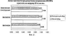
на фиг.2 представлена диаграмма сравнительной оценки механических свойств заявляемой конструкции и действующих конструкций железнодорожных колес;figure 2 presents a diagram of a comparative assessment of the mechanical properties of the claimed structure and the existing structures of railway wheels;
на фиг.3 представлены диаграммы сравнительной оценки термомеханических свойств заявляемой конструкции и действующих конструкций железнодорожных колес.figure 3 presents diagrams of a comparative assessment of the thermomechanical properties of the claimed design and the existing structures of railway wheels.
Железнодорожное колесо, изображенное на фиг.1, имеет центральную плоскость Р, перпендикулярную оси вращения колеса Z, которое включает в себя обод 1, сформированный поверхностью катания 2 и гребнем 3, ступицу 4 и диск 5, образованный наружной 6 и внутренней 7 поверхностями, выполненный таким образом, что теоретическая средняя линия 8 поперечного профиля диска 5 проходит через первую точку А, расположенную в месте сопряжения диска 5 с ободом 1, центральную точку С, где теоретическая средняя линия 8 имеет максимальное от центральной плоскости Р смещение в сторону, противоположенную гребню 3, и вторую точку В, находящуюся в месте сопряжения диска 5 со ступицей 4. Указанная центральная плоскость Р диска 5 колеса проходит через обод 1 колеса в месте замера диаметра круга катания D.The railway wheel shown in figure 1, has a Central plane P perpendicular to the axis of rotation of the wheel Z, which includes a rim 1 formed by the rolling surface 2 and the ridge 3, the hub 4 and the disk 5 formed by the outer 6 and inner 7 surfaces, made so that the theoretical center line 8 of the transverse profile of the disk 5 passes through the first point A located at the interface between the disk 5 and the rim 1, the center point C, where the theoretical center line 8 has a maximum offset from the central plane P the direction opposite to the ridge 3, and the second point B, located at the interface between the disk 5 and the hub 4. The specified central plane P of the wheel 5 passes through the rim 1 of the wheel in the place of measuring the diameter of the skating circle D.
Наружная поверхность 6 диска 5 образована со стороны обода 1 первой наружной радиусной кривой R1 и со стороны ступицы 4 второй наружной радиусной кривой R2 с кривизной, совпадающей по направлению с кривизной первой наружной радиусной кривой R1, сопряженных между собой в центральной части диска 5 третьей R3 со стороны обода 1 и четвертой R4 со стороны ступицы 4 наружными радиусными кривыми с кривизной, противоположной по направлению кривизне первой R1 и второй R2 наружных радиусных кривых, а внутренняя поверхность 7 диска 5 образована со стороны обода 1 первой внутренней радиусной кривой R5 и со стороны ступицы 4 второй внутренней радиусной кривой R6 с кривизной, совпадающей по направлению с кривизной первой внутренней радиусной кривой R5, сопряженных между собой в центральной части диска 5 третьей R7 со стороны обода 1 и четвертой R8 со стороны ступицы 4 внутренними радиусными кривыми с кривизной, противоположной по направлению кривизне первой R5 и второй R6 внутренних радиусных кривых.The outer surface 6 of the disk 5 is formed from the side of the rim 1 of the first outer radius curve R1 and from the hub 4 of the second outer radius curve R2 with a curvature coinciding in direction with the curvature of the first outer radius curve R1 conjugated to each other in the central part of the disk 5 of the third R3 with the sides of the rim 1 and the fourth R4 from the hub 4 with outer radius curves with a curvature opposite in direction to the curvature of the first R1 and second R2 of the outer radius curves, and the inner surface 7 of the disk 5 is formed from the side of the rim 1 of the first internal radius curve R5 and from the hub 4 of the second internal radius curve R6 with the curvature coinciding in direction with the curvature of the first internal radius curve R5, mated to each other in the central part of the disk 5 of the third R7 from the side of the rim 1 and the fourth R8 from the side of the hub 4 by internal radius curves with curvature opposite in direction to the curvature of the first R5 and second R6 of the internal radius curves.
Первая точка А смещена на расстояние Н1 не более 0,08 ширины обода Н от центральной плоскости Р в противоположном к гребню 3 направлении, центральная точка С смещена от центральной плоскости Р на расстояние Н2 в интервале значений от 0,35 до 0,4 ширины обода Н, а вторая точка В смещена на расстояние НЗ не более 0,1 ширины обода Н от центральной плоскости Р в направлении к гребню 3.The first point A is offset by a distance H1 of not more than 0.08 of the rim width H from the central plane P in the opposite direction to the ridge 3, the central point C is offset from the central plane P by a distance H2 in the range from 0.35 to 0.4 of the rim width H, and the second point B is shifted by a distance NZ of not more than 0.1 of the width of the rim H from the central plane P in the direction of the ridge 3.
Соотношение толщины Т1 диска 5 в первой точке А к толщине Т2 диска 5 во второй точке В составляет от 0,7 до 1,1, а соотношение толщины ТЗ диска 5 в центральной точке С к толщине Т2 во второй точке В составляет от 0,7 до 0,9.The ratio of the thickness T1 of the disk 5 at the first point A to the thickness T2 of the disk 5 at the second point B is from 0.7 to 1.1, and the ratio of the thickness T3 of the disk 5 at the central point C to the thickness T2 at the second point B is from 0.7 up to 0.9.
Выбор оптимальной формы диска колеса согласно изобретению осуществлен с использованием серии конечно-элементных расчетов различных вариантов конструкций по методикам, описанным в стандарте UIC 510-5 и отчете UIC В 169/RP 17, которые позволяют определять напряженно-деформированное состояние колеса от действия механических и термических нагрузок, наиболее критичных при эксплуатации.The selection of the optimal wheel disk shape according to the invention was carried out using a series of finite element calculations of various design options according to the methods described in UIC 510-5 and UIC report 169 / RP 17, which allow determining the stress-strain state of a wheel from mechanical and thermal effects. loads most critical during operation.
По результатам проведенных согласно требованиям EN 13979-1 расчетов заявляемая конструкция, как показано на фиг.2, имеет лучшие в сравнении с аналогичными по назначению конструкциями колес ВА 314/324 и ВА 318/319 характеристики усталостной прочности диска наряду с обеспечением меньшей конструкционной массы на 7 и 19 кг соответственно.According to the results of the calculations carried out in accordance with the requirements of EN 13979-1, the claimed design, as shown in Fig. 2, has better compared to similarly designed wheel designs BA 314/324 and BA 318/319 the characteristics of the fatigue strength of the disk along with providing a lower structural weight by 7 and 19 kg, respectively.
Результаты компьютерного моделирования стендовых испытаний при торможении колес, приведенные на фиг.3 и выполненные согласно UIC В 169/RP 17, характеризуют заявляемую конструкцию уровнем напряжений в диске и степенью боковой деформации обода, сопоставимых с существующими аналогами.The results of computer simulation of bench tests when braking wheels, shown in figure 3 and performed according to UIC B 169 / RP 17, characterize the claimed design by the level of stresses in the disk and the degree of lateral deformation of the rim, comparable with existing analogues.
Проведенный заявителем анализ уровня техники, включающий поиск по патентным и научно-техническим источникам информации, и выявление источников, содержащих сведения об аналогах заявляемого изобретения, позволили установить, что заявитель не обнаружил аналог, характеризующийся признаками, тождественными (идентичными) всем существенным признакам заявляемого изобретения.The analysis of the prior art by the applicant, including a search by patent and scientific and technical sources of information, and the identification of sources containing information about analogues of the claimed invention, allowed to establish that the applicant did not find an analogue characterized by features identical (identical) to all essential features of the claimed invention.
Определение из перечня выявленных аналогов прототипа позволило выявить совокупность существенных по отношению к усматриваемому техническому результату отличительных признаков в заявляемом «Железнодорожном колесе», изложенных в формуле изобретения.The definition from the list of identified analogues of the prototype made it possible to identify a set of essential distinguishing features with respect to the technical result in the claimed “Railway Wheel” set forth in the claims.
Результаты поиска показали, что заявляемое изобретение не вытекает для специалиста явным образом из известного уровня техники, определенного заявителем, не выявлено влияние предусматриваемых существенными признаками заявляемого изобретения преобразований на достижение технического результата.The search results showed that the claimed invention does not follow explicitly from the prior art determined by the applicant for the specialist, the effect of the transformations provided for by the essential features of the claimed invention on the achievement of the technical result is not revealed.
Предлагаемое изобретение может использоваться для всех моделей железнодорожных транспортных средств, на которых применяются колодочные тормоза, особенно для железнодорожных грузовых вагонов, ведущих транспортных средств и локомотивов. Хорошая согласованность усталостной прочности в критических зонах колеса - в местах перехода диска колеса в ступицу и обод, позволяет использовать данную конструкцию также для железнодорожного транспорта, где вместо колодочного тормоза используются дисковые тормоза, что имеет место применительно к пассажирским вагонам. Колесо, согласно изобретению, может быть изготовлено из стали любого качества, используемого в железнодорожной промышленности, и произведено в соответствии с известными техническими требованиями и стандартами, раскаткой, штамповкой или литьем.The present invention can be used for all models of railway vehicles that use shoe brakes, especially for railway freight cars, driving vehicles and locomotives. Good consistency of fatigue strength in critical areas of the wheel — at the places where the wheel goes into the hub and rim — allows this design to also be used for railway transport, where disc brakes are used instead of the shoe brake, which is the case with passenger cars. The wheel according to the invention can be made of steel of any quality used in the railway industry and produced in accordance with known technical requirements and standards, rolling, stamping or casting.
Теоретические исследования и испытания железнодорожных колес с конфигурацией диска, согласно заявленной формуле, применительно к грузовым вагонам для сети европейских железных дорог показали соответствие всем требованиям безопасности и способность обеспечения оптимального уровня эксплуатационных характеристик колес. Этим доказывается достижение усматриваемого заявителем технического результата.Theoretical research and testing of railway wheels with a disk configuration, according to the stated formula, as applied to freight cars for a network of European railways, showed compliance with all safety requirements and the ability to ensure the optimal level of wheel performance. This proves the achievement of the technical result perceived by the applicant.
Claims (1)
Priority Applications (16)
| Application Number | Priority Date | Filing Date | Title |
|---|---|---|---|
| RU2011151692/11A RU2486063C1 (en) | 2011-12-16 | 2011-12-16 | Railway wheel |
| PL12858606T PL2792502T3 (en) | 2011-12-16 | 2012-12-14 | Railway wheel |
| CA2866669A CA2866669C (en) | 2011-12-16 | 2012-12-14 | Railway wheel |
| JP2014547138A JP6058024B2 (en) | 2011-12-16 | 2012-12-14 | Railway wheels |
| CN201280061859.2A CN104136235B (en) | 2011-12-16 | 2012-12-14 | Railway wheel |
| SI201231473T SI2792502T1 (en) | 2011-12-16 | 2012-12-14 | Railway wheel |
| EP12858606.2A EP2792502B1 (en) | 2011-12-16 | 2012-12-14 | Railway wheel |
| IN5689DEN2014 IN2014DN05689A (en) | 2011-12-16 | 2012-12-14 | |
| US14/365,605 US9321305B2 (en) | 2011-12-16 | 2012-12-14 | Railway wheel |
| ES12858606.2T ES2693103T3 (en) | 2011-12-16 | 2012-12-14 | Railway wheel |
| PCT/RU2012/001072 WO2013089596A1 (en) | 2011-12-16 | 2012-12-14 | Railway wheel |
| AU2012353050A AU2012353050B2 (en) | 2011-12-16 | 2012-12-14 | Railway wheel |
| UAA201407803A UA111763C2 (en) | 2011-12-16 | 2012-12-14 | RAIL WHEEL |
| RS20181436A RS58144B1 (en) | 2011-12-16 | 2012-12-14 | Railway wheel |
| BR112014014208-4A BR112014014208B1 (en) | 2011-12-16 | 2012-12-14 | railway wheels |
| HRP20181970TT HRP20181970T1 (en) | 2011-12-16 | 2018-11-26 | Railway wheel |
Applications Claiming Priority (1)
| Application Number | Priority Date | Filing Date | Title |
|---|---|---|---|
| RU2011151692/11A RU2486063C1 (en) | 2011-12-16 | 2011-12-16 | Railway wheel |
Publications (1)
| Publication Number | Publication Date |
|---|---|
| RU2486063C1 true RU2486063C1 (en) | 2013-06-27 |
Family
ID=48612917
Family Applications (1)
| Application Number | Title | Priority Date | Filing Date |
|---|---|---|---|
| RU2011151692/11A RU2486063C1 (en) | 2011-12-16 | 2011-12-16 | Railway wheel |
Country Status (16)
| Country | Link |
|---|---|
| US (1) | US9321305B2 (en) |
| EP (1) | EP2792502B1 (en) |
| JP (1) | JP6058024B2 (en) |
| CN (1) | CN104136235B (en) |
| AU (1) | AU2012353050B2 (en) |
| BR (1) | BR112014014208B1 (en) |
| CA (1) | CA2866669C (en) |
| ES (1) | ES2693103T3 (en) |
| HR (1) | HRP20181970T1 (en) |
| IN (1) | IN2014DN05689A (en) |
| PL (1) | PL2792502T3 (en) |
| RS (1) | RS58144B1 (en) |
| RU (1) | RU2486063C1 (en) |
| SI (1) | SI2792502T1 (en) |
| UA (1) | UA111763C2 (en) |
| WO (1) | WO2013089596A1 (en) |
Cited By (6)
| Publication number | Priority date | Publication date | Assignee | Title |
|---|---|---|---|---|
| RU2628025C1 (en) * | 2016-08-31 | 2017-08-14 | Акционерное общество "Выксунский металлургический завод" | Whole-rolled railway wheel |
| RU187467U1 (en) * | 2018-02-08 | 2019-03-06 | РЕЙЛ 1520 АйПи ЛТД | RAILWAY WHEEL |
| RU2689642C1 (en) * | 2017-12-28 | 2019-05-28 | РЕЙЛ 1520 АйПи ЛТД | Railway wheel |
| RU2722782C1 (en) * | 2019-05-31 | 2020-06-03 | АО "ЕВРАЗ Нижнетагильский металлургический комбинат" (АО "ЕВРАЗ НТМК) | Railway wheel |
| RU2770044C1 (en) * | 2021-10-21 | 2022-04-14 | Акционерное общество "ЕВРАЗ Нижнетагильский металлургический комбинат" | Rail transport wheel |
| RU2788741C1 (en) * | 2022-06-28 | 2023-01-24 | Реларт С.А. | Solid rolled railway wheel |
Families Citing this family (10)
| Publication number | Priority date | Publication date | Assignee | Title |
|---|---|---|---|---|
| CN106142979B (en) * | 2016-06-29 | 2018-10-30 | 西南交通大学 | Rail vehicle S-shaped web pattern wheel with three sections of tangent arcs |
| CN107415576B (en) * | 2017-07-18 | 2020-04-14 | 上海工程技术大学 | 3S-shaped spoke plate structure of urban rail transit vehicle wheel |
| CN108501615A (en) * | 2018-04-25 | 2018-09-07 | 马钢(集团)控股有限公司 | A kind of bending disc rail wheel |
| CN108787968B (en) * | 2018-05-21 | 2019-11-12 | 马鞍山钢铁股份有限公司 | Anti- disc rim plate is away from big difference train wheel heat forming technology |
| US11897281B2 (en) | 2019-05-29 | 2024-02-13 | Nippon Steel Corporation | Wheel for railway vehicle |
| JP2021109525A (en) * | 2020-01-09 | 2021-08-02 | 日本製鉄株式会社 | Railway wheel |
| CN114523803B (en) * | 2022-03-14 | 2024-03-08 | 宝武集团马钢轨交材料科技有限公司 | Lightweight heavy-duty wheel set and design method thereof |
| WO2024053617A1 (en) * | 2022-09-08 | 2024-03-14 | 日本製鉄株式会社 | Wheel |
| WO2024075367A1 (en) * | 2022-10-04 | 2024-04-11 | 日本製鉄株式会社 | Wheel |
| CZ202324A3 (en) | 2023-01-25 | 2024-08-07 | Bonatrans Group A.S. | A rail wheel |
Citations (6)
| Publication number | Priority date | Publication date | Assignee | Title |
|---|---|---|---|---|
| DE1405588A1 (en) * | 1961-08-16 | 1969-01-30 | Krupp Ag Huettenwerke | Disc of a wheel disc |
| DE3117572A1 (en) * | 1980-07-03 | 1982-09-09 | VEB Radsatzfabrik Ilsenburg, DDR 3705 Ilsenburg | Solid wheel for rail vehicles |
| RU2085403C1 (en) * | 1995-04-11 | 1997-07-27 | Всероссийский научно-исследовательский институт железнодорожного транспорта | Seemless rolled wheel for railway vehicles |
| EP1470006A1 (en) * | 2002-01-28 | 2004-10-27 | Bonatrans A.S. | A disc for railway wheel |
| RU2259279C1 (en) * | 2004-01-15 | 2005-08-27 | Открытое Акционерное Общество "Выксунский Металлургический Завод" | Solid-rolled wheel and method of its manufacture |
| RU2408469C2 (en) * | 2006-09-13 | 2011-01-10 | Открытое Акционерное Общество "Интерпайп Нижнеднепровский Трубопрокатный Завод" | All-rolled railroad wheel |
Family Cites Families (9)
| Publication number | Priority date | Publication date | Assignee | Title |
|---|---|---|---|---|
| FR1320237A (en) * | 1961-02-17 | 1963-03-08 | Asea Ab | Wheel for vehicles running on rails |
| JPH03504112A (en) * | 1989-02-17 | 1991-09-12 | ドネプロペトロフスキー、メタルルギチェスキー、インスチツート | railway wheels |
| CN1047053A (en) * | 1989-05-06 | 1990-11-21 | “勃列日涅夫”德聂伯罗彼特罗夫斯克冶金研究院 | Railway wheel |
| US5339926A (en) * | 1993-06-01 | 1994-08-23 | Mccanse Engineering, Incorporated | Vehicle service lift |
| US5957517A (en) * | 1998-11-17 | 1999-09-28 | Chen; Yu-Fu | Structure clamp device for the clinching and conveyance of unusually shaped objects |
| ES2192437B2 (en) * | 2000-12-15 | 2005-07-01 | Construcciones Y Auxiliar De Ferrocarriles, S.A. | RAILWAY WHEEL. |
| DE60115832T2 (en) * | 2001-01-17 | 2006-07-27 | Construcciones Y Auxiliar de Ferrocarriles, S.A. -CAF-, Beasain | railway wheel |
| ITBS20060172A1 (en) * | 2006-08-04 | 2008-02-05 | Lucchini Sidermeccanica Spa | WHEEL FOR RAILWAY VEHICLES WITH HIGH BRACING CAPACITY |
| RU2376149C1 (en) * | 2008-03-11 | 2009-12-20 | Открытое акционерное общество "Нижнетагильский металлургический комбинат" (ОАО "НТМК") | All-rolled wheel for railway transport |
-
2011
- 2011-12-16 RU RU2011151692/11A patent/RU2486063C1/en active
-
2012
- 2012-12-14 PL PL12858606T patent/PL2792502T3/en unknown
- 2012-12-14 IN IN5689DEN2014 patent/IN2014DN05689A/en unknown
- 2012-12-14 JP JP2014547138A patent/JP6058024B2/en not_active Expired - Fee Related
- 2012-12-14 SI SI201231473T patent/SI2792502T1/en unknown
- 2012-12-14 CN CN201280061859.2A patent/CN104136235B/en active Active
- 2012-12-14 AU AU2012353050A patent/AU2012353050B2/en not_active Ceased
- 2012-12-14 EP EP12858606.2A patent/EP2792502B1/en active Active
- 2012-12-14 BR BR112014014208-4A patent/BR112014014208B1/en not_active IP Right Cessation
- 2012-12-14 UA UAA201407803A patent/UA111763C2/en unknown
- 2012-12-14 US US14/365,605 patent/US9321305B2/en not_active Expired - Fee Related
- 2012-12-14 RS RS20181436A patent/RS58144B1/en unknown
- 2012-12-14 ES ES12858606.2T patent/ES2693103T3/en active Active
- 2012-12-14 CA CA2866669A patent/CA2866669C/en not_active Expired - Fee Related
- 2012-12-14 WO PCT/RU2012/001072 patent/WO2013089596A1/en active Application Filing
-
2018
- 2018-11-26 HR HRP20181970TT patent/HRP20181970T1/en unknown
Patent Citations (7)
| Publication number | Priority date | Publication date | Assignee | Title |
|---|---|---|---|---|
| DE1405588A1 (en) * | 1961-08-16 | 1969-01-30 | Krupp Ag Huettenwerke | Disc of a wheel disc |
| DE3117572A1 (en) * | 1980-07-03 | 1982-09-09 | VEB Radsatzfabrik Ilsenburg, DDR 3705 Ilsenburg | Solid wheel for rail vehicles |
| SU1139647A1 (en) * | 1980-07-03 | 1985-02-15 | Феб Радзатцфабрик Илзенбург (Инопредприятие) | Seamless rolled wheel of railway vehicle |
| RU2085403C1 (en) * | 1995-04-11 | 1997-07-27 | Всероссийский научно-исследовательский институт железнодорожного транспорта | Seemless rolled wheel for railway vehicles |
| EP1470006A1 (en) * | 2002-01-28 | 2004-10-27 | Bonatrans A.S. | A disc for railway wheel |
| RU2259279C1 (en) * | 2004-01-15 | 2005-08-27 | Открытое Акционерное Общество "Выксунский Металлургический Завод" | Solid-rolled wheel and method of its manufacture |
| RU2408469C2 (en) * | 2006-09-13 | 2011-01-10 | Открытое Акционерное Общество "Интерпайп Нижнеднепровский Трубопрокатный Завод" | All-rolled railroad wheel |
Cited By (9)
| Publication number | Priority date | Publication date | Assignee | Title |
|---|---|---|---|---|
| RU2628025C1 (en) * | 2016-08-31 | 2017-08-14 | Акционерное общество "Выксунский металлургический завод" | Whole-rolled railway wheel |
| RU2689642C1 (en) * | 2017-12-28 | 2019-05-28 | РЕЙЛ 1520 АйПи ЛТД | Railway wheel |
| EA034345B1 (en) * | 2017-12-28 | 2020-01-29 | РЕЙЛ 1520 АйПи ЛТД. | Railway wheel |
| RU187467U1 (en) * | 2018-02-08 | 2019-03-06 | РЕЙЛ 1520 АйПи ЛТД | RAILWAY WHEEL |
| RU2722782C1 (en) * | 2019-05-31 | 2020-06-03 | АО "ЕВРАЗ Нижнетагильский металлургический комбинат" (АО "ЕВРАЗ НТМК) | Railway wheel |
| RU2770044C1 (en) * | 2021-10-21 | 2022-04-14 | Акционерное общество "ЕВРАЗ Нижнетагильский металлургический комбинат" | Rail transport wheel |
| WO2023068966A1 (en) | 2021-10-21 | 2023-04-27 | Акционерное общество "ЕВРАЗ Нижнетагильский металлургический комбинат" | Railway vehicle wheel |
| RU2788741C1 (en) * | 2022-06-28 | 2023-01-24 | Реларт С.А. | Solid rolled railway wheel |
| RU2807770C1 (en) * | 2023-06-19 | 2023-11-21 | Акционерное общество "Выксунский металлургический завод" (АО "ВМЗ") | Solid wheel |
Also Published As
| Publication number | Publication date |
|---|---|
| CA2866669C (en) | 2017-06-27 |
| WO2013089596A1 (en) | 2013-06-20 |
| PL2792502T3 (en) | 2019-02-28 |
| UA111763C2 (en) | 2016-06-10 |
| SI2792502T1 (en) | 2019-01-31 |
| HRP20181970T1 (en) | 2019-02-08 |
| CN104136235A (en) | 2014-11-05 |
| JP2015500177A (en) | 2015-01-05 |
| AU2012353050A1 (en) | 2014-07-10 |
| US9321305B2 (en) | 2016-04-26 |
| RS58144B1 (en) | 2019-02-28 |
| EP2792502A1 (en) | 2014-10-22 |
| EP2792502B1 (en) | 2018-09-19 |
| ES2693103T3 (en) | 2018-12-07 |
| US20140300122A1 (en) | 2014-10-09 |
| IN2014DN05689A (en) | 2015-04-03 |
| CA2866669A1 (en) | 2013-06-20 |
| EP2792502A4 (en) | 2017-03-22 |
| AU2012353050B2 (en) | 2016-09-22 |
| BR112014014208B1 (en) | 2020-10-27 |
| CN104136235B (en) | 2016-05-25 |
| BR112014014208A2 (en) | 2017-06-13 |
| JP6058024B2 (en) | 2017-01-11 |
Similar Documents
| Publication | Publication Date | Title |
|---|---|---|
| RU2486063C1 (en) | Railway wheel | |
| CN101500822B (en) | Railway wheel | |
| CN104603491A (en) | Brake disc for railway vehicle | |
| US9784329B2 (en) | Composite brake drum with bands | |
| TWI572790B (en) | Railway wheel with brake disc | |
| EP1470006B1 (en) | A disc for railway wheel | |
| JP5478293B2 (en) | Tires for new transportation vehicles | |
| JPH10119503A (en) | Wheel for railway rolling stock excellent in crack resistance and its manufacture | |
| RU2428319C1 (en) | Railroad wheel | |
| JP2021109525A (en) | Railway wheel | |
| RU2722782C1 (en) | Railway wheel | |
| KR101874216B1 (en) | Railroad wheel with brake disc | |
| RU2376149C1 (en) | All-rolled wheel for railway transport | |
| RU2628025C1 (en) | Whole-rolled railway wheel | |
| CN108621676A (en) | A kind of production method for wheel and wheel | |
| JP5126903B2 (en) | Fastening structure of railcar brake disc and railcar wheel axle | |
| CN113879041A (en) | Railway wheel with small deformation | |
| JP4600194B2 (en) | Fastening structure of railcar brake disc and railcar wheel | |
| JP4168512B2 (en) | Wheels with brake discs for railway vehicles | |
| WO2022091764A1 (en) | Wheel for railway vehicle | |
| RU2386545C2 (en) | Solid-rolled railroad wheel | |
| KR20240111098A (en) | Brake disk | |
| RU2245794C1 (en) | Vehicle wheel | |
| CN114290850A (en) | Low-stress reverse S-shaped spoke plate wheel and design method thereof | |
| Sahu et al. | Parametric Study of Hub Cum Brake Drum for Optimum Design Performance |
Legal Events
| Date | Code | Title | Description |
|---|---|---|---|
| PD4A | Correction of name of patent owner |