WO2022091665A1 - 車載用コネクタ - Google Patents
車載用コネクタ Download PDFInfo
- Publication number
- WO2022091665A1 WO2022091665A1 PCT/JP2021/035322 JP2021035322W WO2022091665A1 WO 2022091665 A1 WO2022091665 A1 WO 2022091665A1 JP 2021035322 W JP2021035322 W JP 2021035322W WO 2022091665 A1 WO2022091665 A1 WO 2022091665A1
- Authority
- WO
- WIPO (PCT)
- Prior art keywords
- electrode
- seal member
- vehicle
- portions
- electrode portions
- Prior art date
Links
- 238000007789 sealing Methods 0.000 claims description 23
- 238000006243 chemical reaction Methods 0.000 claims description 17
- 230000006835 compression Effects 0.000 claims description 8
- 238000007906 compression Methods 0.000 claims description 8
- 239000003921 oil Substances 0.000 description 8
- 230000000694 effects Effects 0.000 description 4
- 238000000034 method Methods 0.000 description 4
- 239000000463 material Substances 0.000 description 3
- 230000002250 progressing effect Effects 0.000 description 3
- 238000010586 diagram Methods 0.000 description 2
- 239000007788 liquid Substances 0.000 description 2
- RYGMFSIKBFXOCR-UHFFFAOYSA-N Copper Chemical compound [Cu] RYGMFSIKBFXOCR-UHFFFAOYSA-N 0.000 description 1
- 229920000181 Ethylene propylene rubber Polymers 0.000 description 1
- 229920000459 Nitrile rubber Polymers 0.000 description 1
- 229920000800 acrylic rubber Polymers 0.000 description 1
- XAGFODPZIPBFFR-UHFFFAOYSA-N aluminium Chemical compound [Al] XAGFODPZIPBFFR-UHFFFAOYSA-N 0.000 description 1
- 229910052782 aluminium Inorganic materials 0.000 description 1
- 238000005452 bending Methods 0.000 description 1
- 239000003638 chemical reducing agent Substances 0.000 description 1
- 229910052802 copper Inorganic materials 0.000 description 1
- 239000010949 copper Substances 0.000 description 1
- 229920001971 elastomer Polymers 0.000 description 1
- 239000008393 encapsulating agent Substances 0.000 description 1
- 229920001973 fluoroelastomer Polymers 0.000 description 1
- 230000010354 integration Effects 0.000 description 1
- 238000012986 modification Methods 0.000 description 1
- 230000004048 modification Effects 0.000 description 1
- 238000007747 plating Methods 0.000 description 1
- 229920000058 polyacrylate Polymers 0.000 description 1
- 239000011347 resin Substances 0.000 description 1
- 229920005989 resin Polymers 0.000 description 1
- 238000007788 roughening Methods 0.000 description 1
- 229920002379 silicone rubber Polymers 0.000 description 1
- 238000005476 soldering Methods 0.000 description 1
- 239000007787 solid Substances 0.000 description 1
- 238000004381 surface treatment Methods 0.000 description 1
Images


Classifications
-
- H—ELECTRICITY
- H01—ELECTRIC ELEMENTS
- H01R—ELECTRICALLY-CONDUCTIVE CONNECTIONS; STRUCTURAL ASSOCIATIONS OF A PLURALITY OF MUTUALLY-INSULATED ELECTRICAL CONNECTING ELEMENTS; COUPLING DEVICES; CURRENT COLLECTORS
- H01R13/00—Details of coupling devices of the kinds covered by groups H01R12/70 or H01R24/00 - H01R33/00
- H01R13/46—Bases; Cases
- H01R13/52—Dustproof, splashproof, drip-proof, waterproof, or flameproof cases
-
- H—ELECTRICITY
- H02—GENERATION; CONVERSION OR DISTRIBUTION OF ELECTRIC POWER
- H02K—DYNAMO-ELECTRIC MACHINES
- H02K5/00—Casings; Enclosures; Supports
- H02K5/04—Casings or enclosures characterised by the shape, form or construction thereof
- H02K5/10—Casings or enclosures characterised by the shape, form or construction thereof with arrangements for protection from ingress, e.g. water or fingers
-
- H—ELECTRICITY
- H02—GENERATION; CONVERSION OR DISTRIBUTION OF ELECTRIC POWER
- H02K—DYNAMO-ELECTRIC MACHINES
- H02K5/00—Casings; Enclosures; Supports
- H02K5/04—Casings or enclosures characterised by the shape, form or construction thereof
- H02K5/22—Auxiliary parts of casings not covered by groups H02K5/06-H02K5/20, e.g. shaped to form connection boxes or terminal boxes
Definitions
- the present invention relates to the structure of an in-vehicle connector.
- Patent Document 1 discloses a mechanism for integrating a housing of an inverter, a motor, and a speed reducer in a drive device including two motors that independently drive the left and right drive wheels.
- Patent Document 1 is a technique for simplifying the connection structure between the inverter and the electric motor.
- a control circuit board for a gearbox is built in a power conversion device, and the control circuit board and each component in the gearbox are connected without using an electric wire.
- a connector structure that directly connects the control circuit board and the gearbox is required.
- the configuration for connecting the gearbox control board built in the power conversion device and each component in the gearbox, such as an actuator, is as follows.
- the actuator has a spring terminal that receives a driving current
- the power conversion device has a connector that electrically connects to the actuator.
- the connector has an electrode portion that comes into contact with the spring terminal due to spring compression, a housing portion that holds the electrode portion, and a seal member that is mounted on the housing portion to prevent intrusion of gearbox oil and the like.
- the housing portion has a sealing surface secured together with the sealing member, and the electrode portion is extended and electrically connected to the gearbox control board.
- the electrode part always receives the spring load from the spring terminal, and the sealing surface is deformed by the spring load, and the sealing performance is deteriorated due to the deformation. Oil intrusion can occur.
- Patent Document 1 does not describe the above-mentioned problems in the connector for integrating the power conversion device and the gearbox. Therefore, no solution is described.
- An object of the present invention is to realize a highly integrated in-vehicle connector capable of suppressing deformation of the sealing surface due to a spring load and suppressing oil intrusion.
- the present invention is configured as follows in order to achieve the above object.
- the in-vehicle connector includes at least two electrode portions that come into direct contact with the terminal portion of the drive unit, a housing portion that holds the electrode portion, and a seal member that is mounted on the housing portion to ensure airtightness.
- the seal member is located above the electrode portion with respect to the load direction received by the electrode portion from the terminal portion.
- the seal member by arranging the seal member in the vicinity directly above the electrode portion in the direction of receiving the spring load, deformation of the seal surface due to the spring load can be suppressed and oil intrusion can be suppressed. It is possible to realize an in-vehicle connector.
- FIG. 3 is a schematic perspective view of a connector structure according to a first embodiment of the present invention. It is a schematic cross-sectional view of the connector structure shown from the viewpoint different from FIG. 1 of Example 1 of this invention. It is a schematic sectional drawing of the connector structure of Example 2 of this invention. It is a schematic perspective view of the connector structure of Example 3 of this invention.
- FIG. 3 is a schematic perspective view of a connector structure shown from a different viewpoint from FIG. 4 of the third embodiment of the present invention. It is a schematic perspective view of the connector structure of Example 4 of this invention.
- FIG. 6 is a schematic perspective view of a connector structure shown from a different viewpoint from FIG. 6 of the fourth embodiment of the present invention.
- FIG. 5 is a schematic cross-sectional view of a connector structure shown from a different viewpoint from FIG. 8 of the fifth embodiment of the present invention. It is the schematic sectional drawing of the connector structure and the power conversion apparatus housing of Example 6 of this invention. It is a schematic block diagram of an example of a highly integrated e-axel system 100.
- FIG. 1 is a schematic perspective view of the connector structure according to the first embodiment of the present invention
- FIG. 2 is a schematic cross-sectional view of the connector structure shown from a different viewpoint from FIG. 1 of the first embodiment of the present invention.
- the pair of electrode portions 1 that come into direct contact with the terminal portion of the actuator described later are held by the housing portion 2.
- the electrode portion 1 is stretched and partially exposed from the housing portion 2 to form the connector terminal portion 10.
- the connector terminal portion 10 is electrically connected to the circuit board that controls the actuator.
- the housing portion 2 has a fixing portion 20 for fixing to the outside.
- the seal member 3 has an annular shape, is held by the housing portion 2, forms a seal surface 4 together with the housing portion 2, and has an airtightness (the airtightness is ensured).
- the seal member 3 has a role of preventing the intrusion of oil, foreign matter, etc. from the outside.
- the electrode portion 1 is electrically connected to the actuator by directly contacting the terminal portion of the actuator.
- the terminal portion of the autuator is provided with a spring mechanism and has elasticity, so that the terminal portion comes into contact with the electrode portion 1 and is compressed to secure an electrical connection.
- the electrode portion 1 receives a load due to the compression of the spring mechanism.
- the material of the electrode portion 1 copper, aluminum, or the like can be considered, and plating treatment may be performed.
- the shape of the electrode portion 1 can be various depending on the contact area of the actuator with the terminal portion and the distance between the terminal portions.
- various shapes from the electrode portion 1 to the connector terminal portion 10 can be considered, and for example, the shape may have a plurality of bending shapes.
- the material of the housing portion 2 may be PBT, PA66, PPS, or the like, depending on the external environment.
- surface treatment such as roughening treatment on the electrode portion 1 or a liquid resin encapsulant having good adhesion to the electrode portion 1 and the housing portion 2 is performed. Etc. may be used.
- silicon rubber, acrylic rubber, nitrile rubber, fluororubber, ethylene propylene rubber, etc. can be considered depending on the external environment. It is also conceivable to apply a liquid seal member and perform a curing reaction to form a solid rubber.
- the size of the seal member 3 depends on the required airtightness, the variation in the flatness of the seal surface 4, the size of the housing portion 2, and the like, and various shapes such as an O-ring and an H-ring can be considered.
- the sealing surface 4 is deformed by the load of the spring mechanism. It is possible to suppress and secure the airtightness.
- Example 2 Next, Example 2 of the present invention will be described.
- FIG. 3 is a schematic cross-sectional view of the connector structure of the second embodiment of the present invention.
- the relationship between the width on the side and ds is a structure that satisfies dmin ⁇ ds (dmn is ds or less) --- .
- Satisfying dmin ⁇ ds means that the seal member 3 is arranged in a region where the deformation of the seal surface 4 due to the load received by the electrode portion 1 is small, which leads to ensuring good airtightness.
- dt2 depends on the position of the terminal portion included in the actuator described later and the like. Further, the distance dt2 also depends on the thickness of the seal member 3 in the compression direction.
- the mounting position of the seal member 3 is set above the electrode portion 1 with respect to the load direction received by the electrode portion 1, and the mounting position is in the normal direction of the load direction received by the electrode portion 1.
- the relationship between the minimum distance dmin and the width on the normal side in the compression direction in the circumferential direction of the annular seal member 3 has a structure that satisfies dmin ⁇ ds --- , and the seal is sealed by the load received by the electrode portion 1. Since the seal member 3 is arranged in the region where the deformation of the surface 4 is small, good airtightness can be ensured.
- Example 3 of the present invention will be described.
- FIG. 4 is a schematic perspective view of the connector structure of the third embodiment of the present invention
- FIG. 5 is a schematic perspective view of the connector structure shown from a different viewpoint from FIG. 4 of the third embodiment of the present invention.
- one housing portion 2 includes a plurality of pairs of electrode portions 1 and one sealing member 3.
- a plurality of pairs of electrode portions 1 are in direct contact with the terminal portions of a plurality of actuators, and the mounting position (arrangement position) of the seal member 3 is set directly above the plurality of pairs of electrode portions 1 with respect to the load direction received from the terminal portions. By setting it to the upper side), it is possible to suppress the deformation of the sealing surface 4 due to the load received by the plurality of pairs of electrode portions 1 and to secure the airtightness.
- Example 3 of the present invention the same effect as in Example 1 can be obtained.
- Example 3 the positional relationship between the seal member 3 and the electrode portion 1 can be set to dmin ⁇ ds shown in Example 2.
- Example 4 of the present invention will be described.
- FIG. 6 is a schematic perspective view of the connector structure of the fourth embodiment of the present invention
- FIG. 7 is a schematic perspective view of the connector structure shown from a different viewpoint from FIG. 6 of the fourth embodiment of the present invention.
- one housing portion 2 includes a plurality of pairs of electrode portions 1 and a plurality of sealing members 3.
- the mounting position (arrangement position) of each of the plurality of seal members 3 is directly above the plurality of pairs of electrode portions 1 with respect to the load direction received by the plurality of pairs of electrode portions 1 being directly connected to the terminal portions of the plurality of actuators.
- it (upper) it is possible to suppress the deformation of the sealing surface 4 due to the above load and ensure the airtightness.
- Example 4 of the present invention the same effect as in Example 1 can be obtained.
- Example 4 the positional relationship between the seal member 3 and the electrode portion 1 can be set to dmin ⁇ ds shown in Example 2.
- Example 5 of the present invention will be described.
- FIG. 8 is a schematic perspective view of the connector structure of the fifth embodiment of the present invention
- FIG. 9 is a schematic cross-sectional view of the connector structure shown from a different viewpoint from FIG. 8 of the fifth embodiment of the present invention.
- the housing portion 2 includes three electrode portions 1 arranged at three locations and at least one seal member 3.
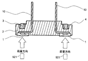
- the three electrode portions 1 are in direct contact with the three terminal portions 921 of the three-phase motor (in FIG. 9, two terminal portions 921 of the three terminal portions 921 are shown) and are loaded.
- the connector terminal portion 10 is electrically connected to the circuit board that controls the three-phase motor.
- the electrode portion 1 receives the load. It is possible to suppress deformation of the sealing surface 4 due to a load and ensure airtightness.
- Example 5 of the present invention the same effect as in Example 1 can be obtained.
- one housing portion 2 is provided with a three-phase electrode portion in which three electrode portions 1 are paired, and a plurality of three-phase electrode portions are formed in one housing portion 2. It is also possible to connect each of the three terminals of the three-phase motor.
- seal members 3 there are a plurality of seal members 3, and the seal members 3 are arranged for each of the three-phase electrode portions, and the three electrode portions 1 are plural with respect to the load direction received from the three terminal portions of the three-phase motor.
- Each of the seal members 3 of the above can be configured to be located directly above each of the three electrode portions 1. Even with such a configuration, it is possible to realize a highly integrated in-vehicle connector capable of suppressing deformation of the sealing surface due to a spring load and suppressing oil intrusion.
- the mounting position of the seal member 3 is set above the electrode portion 1 with respect to the load direction received by the electrode portion 1, and the method in the load direction received by the electrode portion 1 is performed.
- the relationship between the minimum distance dm in the linear direction and the width on the normal side in the compression direction in the circumferential direction of the annular seal member 3 with ds can be configured to satisfy dmin ⁇ ds --- .
- Example 6 of the present invention will be described.
- FIG. 10 is a schematic cross-sectional view of the connector structure and the power conversion device housing of the sixth embodiment of the present invention.
- the connector 40 has the connector structure of the first to fifth embodiments. Although the detailed shape is abbreviated, at least one connector 40 is mounted on the housing 50 of the power conversion device. The number and position of the connector 40 mounted depends on the actuator 80 having the actuator spring terminal (terminal portion) 81 electrically connected to the connector 40, or abbreviated as the number and position of the three-phase motor.
- the power conversion device includes (mounts) an actuator 80 or a drive circuit board 60 that controls a three-phase motor, and the drive circuit board 60 is electrically connected to the connector 40 by a connection portion 70.
- a connection portion 70 soldering, press fitting, caulking fixing and the like can be considered.
- the mounting location of the power conversion device may be, for example, an actuator 80 or a gearbox equipped with a three-phase motor, and may be considered as a partial function of a highly integrated e-axel system.
- FIG. 11 is a schematic configuration diagram of an example of a highly integrated e-axel system 100.
- the power conversion device 90 provided with the electronic control device (ATCU) 91 is mounted on a gearbox 93 equipped with a three-phase motor 92 or an actuator 80 (however, the actuator 80 is not shown in FIG. 11).
- the three-phase motor 92 or the actuator 80 mounted in the gearbox 93 is electrically connected to the drive circuit board 60 mounted on the power conversion device 90 by the connector 40.
- Example 6 of the present invention the same effect as in Example 1 can be obtained.
- the actuator 80 and the three-phase motor 92 can be collectively referred to as a drive unit.
- Electrode part, 2 ... Housing part, 3 ... Seal member, 4 ... Seal surface, 10 ... Connector terminal part, 11 ... Electrode part side surface part, 20 ... Fixed Part, 31 ... Seal member side surface, 40 ... Connector, 50 ... Power converter housing, 60 ... Drive circuit board, 70 ... Connection, 80 ... Actuator, 81 ... Actuator spring terminal, 90 ... Power converter, 91 ... Electronic control device, 92 ... Three-phase motor, 93 ... Gearbox, 100 ... Highly integrated e-axel System, 921 ... Terminal part of 3-phase motor
Landscapes
- Engineering & Computer Science (AREA)
- Power Engineering (AREA)
- Connector Housings Or Holding Contact Members (AREA)
Abstract
車載用コネクタは、駆動部(80、92)が有する端子部(81、921)と直接接触する少なくとも2つの電極部1と、電極部1を保持するハウジング部21と、ハウジング部2に搭載され、密閉性を確保するシール部材3と、を備える。シール部材3は、電極部1が端子部(81、921)より受ける荷重方向に対して、電極部1の上方に位置する。これにより、ばね荷重によるシール面4の変形を抑制する。
Description
本発明は、車載用コネクタの構造に関する。
自動車の電動化が急速に進んでいる。特許文献1には、左右の駆動輪をそれぞれ、独立に駆動する2つの電動機を備える駆動装置において、インバータ、電動機及び減速機のハウジングを一体化する機構が開示されている。
特許文献1に開示された技術は、インバータと電動機との間の接続構造を簡素化する技術である。
ところで、自動車の電動化が急速に進み、ハイブリット自動車や電気自動車等の駆動モータに電流を供給する電力変換装置の需要が高まると同時に、駆動モータ、電力変換装置及びギアボックスを一体化したe-axleの需要も高まっており、高度一体化e-axelの開発も進んでいる。
高度一体化の一例として、ギアボックス用制御回路基板を電力変換装置に内蔵し、制御回路基板とギアボックス内の各構成部品を、電線を介さず接続する構造がある。電線を介さず接続するためには、制御回路基板とギアボックスを直接接続するコネクタ構造が必要となる。
電力変換装置に内蔵されているギアボックス用制御基板とギアボックス内の各構成部品、例えばアクチュエータ等を接続する構成としては、次のような構成がある。
アクチュエータは、駆動用電流を受けるばね端子を有し、電力変換装置は、アクチュエータと電気的に接続するコネクタを有する。そして、コネクタは、ばね端子のばね圧縮によって接触する電極部と、この電極部を保持するハウジング部と、このハウジング部に搭載し、ギアボックスオイル等の侵入を防ぐシール部材とを有する。ハウジング部は、シール部材と共に確保されるシール面を有し、電極部は延伸して、ギアボックス用制御基板と電気的に接続している。
しかしながら、アクチュエータとギアボックス用制御基板の電気的接続を確保する為に、電極部は常にばね端子からばね荷重を受け続けており、ばね荷重によるシール面の変形、ひいては変形によるシール性能の低下、オイルの侵入が起こり得る。
このため、ばね荷重によるシール面の変形を抑制する技術が望まれる。
特許文献1には、電力変換装置及びギアボックスを一体化するコネクタにおける上記課題については記載されていない。このため、解決手段についても、記載されていない。
本発明の目的は、ばね荷重によるシール面の変形を抑制し、オイルの侵入を抑止可能な高度一体化車載用コネクタを実現することである。
本発明は、上記目的を達成するために、次のように構成される。
車載用コネクタにおいて、駆動部が有する端子部と直接接触する少なくとも2つの電極部と、前記電極部を保持するハウジング部と、前記ハウジング部に搭載され、密閉性を確保するシール部材と、を備え、前記シール部材は、前記電極部が端子部より受ける荷重方向に対して、前記電極部の上方に位置する。
本発明によれば、シール部材を、ばね荷重を受ける方向に対して、電極部の直上近傍に配置することで、ばね荷重によるシール面の変形を抑制し、オイルの侵入を抑止可能な高度一体化車載用コネクタを実現することができる。
以下、本発明に係る実施形態を図面に基づいて詳述する。
(実施例1)
図1は、本発明の実施例1によるコネクタ構造の概略斜視図であり、図2は、本発明の実施例1の図1とは別視点で示したコネクタ構造の概略断面図である。
図1は、本発明の実施例1によるコネクタ構造の概略斜視図であり、図2は、本発明の実施例1の図1とは別視点で示したコネクタ構造の概略断面図である。
図1及び図2において、後述するアクチュエータが有する端子部と直接接触する一対の電極部1は、ハウジング部2に保持されている。電極部1は、延伸し、ハウジング部2から一部露出しており、コネクタ端子部10を形成している。略記するが、コネクタ端子部10は、アクチュエータを制御する回路基板と電気的に接続する。
ハウジング部2は、外部と固定する為の固定部20を有する。シール部材3は環状であり、ハウジング部2に保持され、ハウジング部2と共にシール面4を形成し、密閉性を有している(密閉性を確保している)。
具体的には、シール部材3は、外部からのオイルや異物等の侵入を防ぐ役割を有する。
電極部1は、アクチュエータが有する端子部と直接接触することで、アクチュエータと電気的に接続している。具体的には、アウチュエータが有する端子部が、ばね機構を備え、伸縮性を有することで、電極部1に接触し、圧縮することにより、電気的接続を確保する。換言すると、電極部1は、ばね機構の圧縮に伴う荷重を受けている。
電極部1が受ける荷重方向(図2に示す矢印の方向)に対して、シール部材3の搭載位置を、電極部1の直上(上方)にすることで、ばね機構の荷重によるシール面4の変形を抑制し、密閉性を確保することが可能になる。
電極部1の材質としては、銅、またはアルミ等が考えられ、めっき処理を施しても良い。電極部1の形状は、アクチュエータが有する端子部との接触面積や、端子部間の間隔で、様々な形状が考えられる。
また、電極部1からコネクタ端子部10に至るまでの形状も様々に考えられ、例えば、複数回の曲げ形状を有しても良い。ハウジング部2の材質は、外部環境に応じて、PBT、PA66及びPPS等が考えられる。電極部1とハウジング部2の密着性を確保する方策としては、電極部1への粗化処理等の表面処理、または電極部1及びハウジング部2に良好な密着性を有する液状樹脂封止材等を用いることが考えられる。
シール部材3の材質としては、外部環境に応じて、シリコンゴム、アクリルゴム、ニトリルゴム、フッ素ゴム、エチレンプロピレンゴム等が考えられる。また、液状シール部材を塗布して硬化反応により、固体ゴム化する事も考えられる。
シール部材3のサイズは、要求される密閉性、シール面4の平面度ばらつき、ハウジング部2のサイズ等に依存し、Oリング、Hリング、等の様々な形状が考えられる。
本発明の実施例1によれば、電極部1が受ける荷重方向に対して、シール部材3の搭載位置を、電極部1の直上にすることで、ばね機構の荷重によるシール面4の変形を抑制し、密閉性を確保する事が可能になる。
よって、ばね荷重によるシール面4の変形を抑制し、オイルの侵入を抑止可能な高度一体化車載用コネクタを実現することができる。
(実施例2)
次に、本発明の実施例2について説明する。
次に、本発明の実施例2について説明する。
図3は、本発明の実施例2のコネクタ構造の概略断面図である。
図3において、シール部材側面部31と電極部側面部11における、電極部1が受ける荷重方向の法線方向への最小距離dminと、環状のシール部材3の周方向における、圧縮方向の法線側の幅をdsとの関係は、dmin≦ds(dminはds以下) ---を満足する構造である。
dmin≦dsを満足する事は、電極部1が受ける荷重によるシール面4の変形が小さい領域に、シール部材3を配置することになり、良好な密閉性を確保することに繋がる。
シール面4から、電極部1が荷重を受ける面までの距離dt1-及び、シール部材3が配置される、ハウジング部2が備える溝形状の底面から、電極部1が荷重を受ける面までの距離dt2は、後述するアクチュエータが備える端子部の位置等に依存する。また、距離dt2については、シール部材3の圧縮方向の厚みにも依存する。
本発明の実施例2によれば、電極部1が受ける荷重方向に対して、シール部材3の搭載位置を、電極部1の上方にして、電極部1が受ける荷重方向の法線方向への最小距離dminと、環状のシール部材3の周方向における、圧縮方向の法線側の幅をdsとの関係を、dmin≦ds---を満足する構造とし、電極部1が受ける荷重によるシール面4の変形が小さい領域に、シール部材3を配置したので、良好な密閉性を確保することができる。
よって、実施例1と同様に、ばね荷重によるシール面4の変形を抑制し、オイルの侵入を抑止可能な高度一体化車載用コネクタを実現することができる。
(実施例3)
次に、本発明の実施例3について説明する。
次に、本発明の実施例3について説明する。
図4は、本発明の実施例3のコネクタ構造の概略斜視図であり、図5は、本発明の実施例3の図4とは別視点で示したコネクタ構造の概略斜視図である。
図4及び図5において、一つのハウジング部2は、複数対の電極部1、及び1つのシール部材3を備えている。複数対の電極部1が複数のアクチュエータの端子部が直接接触して、端子部から受ける荷重方向に対して、シール部材3の搭載位置(配置位置)を、複数対の電極部1の直上(上方)にすることで、複数対の電極部1が受ける荷重によるシール面4の変形を抑制し、密閉性を確保することが可能になる。
本発明の実施例3においても、実施例1と同様な効果を得ることができる。
なお、実施例3において、シール部材3と電極部1との位置関係を実施例2に示したdmin≦dsとすることも可能である。
(実施例4)
次に、本発明の実施例4について説明する。
次に、本発明の実施例4について説明する。
図6は、本発明の実施例4のコネクタ構造の概略斜視図であり、図7は、本発明の実施例4の図6とは別視点で示したコネクタ構造の概略斜視図である。
図6及び図7において、一つのハウジング部2は、複数対の電極部1、及び複数のシール部材3を備えている。複数対の電極部1が複数のアクチュエータの端子部が直接接続することで受ける荷重方向に対して、複数のシール部材3の各々の搭載位置(配置位置)を、複数対の電極部1の直上(上方)にすることで、上記荷重によるシール面4の変形を抑制し、密閉性を確保することが可能になる。
本発明の実施例4においても、実施例1と同様な効果を得ることができる。
なお、実施例4において、シール部材3と電極部1との位置関係を実施例2に示したdmin≦dsとすることも可能である。
(実施例5)
次に、本発明の実施例5について説明する。
次に、本発明の実施例5について説明する。
図8は、本発明の実施例5のコネクタ構造の概略斜視図であり、図9は、本発明の実施例5の図8とは別視点で示したコネクタ構造の概略断面図である。
図8及び図9において、ハウジング部2は、3箇所に配置された3つの電極部1、及び少なくとも1つのシール部材3を備えている。3つの電極部1は、3相電動機が有する3つの端子部921(図9では3つの端子部921のうちの2つの端子部921を示している)と直接接触し、荷重を受けている。
また、略記するが、コネクタ端子部10は、3相電動機を制御する回路基板と電気的に接続している。
3箇所に配置された電極部1が受ける荷重方向に対して、シール部材3の搭載位置(配置位置)を、3箇所に配置された電極部1の直上にする事で、電極部1が受ける荷重によるシール面4の変形を抑制し、密閉性を確保する事が可能になる。
本発明の実施例5においても、実施例1と同様な効果を得ることができる。
なお、実施例5において、一つのハウジング部2に対して、3つの電極部1を一組とする3相電極部とし、一つのハウジング部2に、複数の3相電極部を形成し、複数の3相電動機が有するそれぞれの3つの端子部を接続する構成とすることもできる。
この場合、シール部材3は複数であり、3相電極部のそれぞれに対してシール部材3が配置され、3つの電極部1が3相電動機の3つの端子部より受ける荷重方向に対して、複数のシール部材3のそれぞれは、3つの電極部1のそれぞれの直上に位置するように構成することができる。このような構成でも、ばね荷重によるシール面の変形を抑制し、オイルの侵入を抑止可能な高度一体化車載用コネクタを実現することができる。
また、実施例5において、実施例2と同様に、電極部1が受ける荷重方向に対して、シール部材3の搭載位置を、電極部1の上方にして、電極部1が受ける荷重方向の法線方向への最小距離dminと、環状のシール部材3の周方向における、圧縮方向の法線側の幅をdsとの関係を、dmin≦ds---を満足する構成とすることもできる。
(実施例6)
次に、本発明の実施例6について説明する。
次に、本発明の実施例6について説明する。
図10は、本発明の実施例6のコネクタ構造及び電力変換装置筐体の概略断面図である。
図10において、コネクタ40は、実施例1乃至実施例5のコネクタ構造を有する。コネクタ40は、詳細形状は略記するが、電力変換装置の筐体50に、少なくとも1つ以上搭載されている。コネクタ40の搭載数及び位置は、コネクタ40と電気的に接続するアクチュエータばね端子(端子部)81を有するアクチュエータ80、もしくは略記するが、3相電動機の搭載数及び位置に依存する。
電力変換装置は、アクチュエータ80、もしくは3相電動機を制御する駆動回路基板60を備え(実装している)、駆動回路基板60は、コネクタ40と接続部70にて電気的に接続している。接続部70としては、はんだ付け、プレスフィット、カシメ固定等が考えられる。
電力変換装置の搭載場所は、例えば、アクチュエータ80、または3相電動機を備えるギアボックス等が考えられ、高度一体化e-axelシステムの一部機能としても考えられる。
図11は、高度一体化e-axelシステム100の一例の概略構成図である。
図11に示した例は、電子制御装置(ATCU)91を備える電力変換装置90が3相電動機92又はアクチュエータ80(ただし、図11ではアクチュエータ80の図示は省略する)を搭載するギアボックス93に搭載される例である。ギアボックス93内に搭載された3相電動機92又はアクチュエータ80がコネクタ40により、電力変換装置90に実装された駆動回路基板60に電気的に接続される。
本発明の実施例6においても、実施例1と同様な効果を得ることができる。
なお、本発明は上記した実施例に限定されるものではなく、様々な変形例が含まれている。
例えば、上述した実施例は本発明を分かりやすく説明する為に詳細に説明したものであり、必ずしも説明した全ての構成を備えるものに限定されるものではない。
また、ある実施例の構成の一部を他の実施例の構成に置き換えることは可能であり、ある実施例の構成に他の実施例の構成を付け加えることも可能である。
また、他の実施例の構成の一部について、他の構成の追加・削除・置換をすることは可能である。例えば、電極部1、ハウジング部2、シール部材3、シール面4、等は様々な形を採用することができる。
なお、アクチュエータ80及び3相電動機92は、駆動部と総称することができる。
1・・・電極部、2・・・ハウジング部、3・・・シール部材、4・・・シール面、10・・・コネクタ端子部、11・・・電極部側面部、20・・・固定部、31・・・シール部材側面部、40・・・コネクタ、50・・・電力変換装置の筐体、60・・・・駆動回路基板、70・・・接続部、80・・・アクチュエータ、81・・・アクチュエータばね端子部、90・・・電力変換装置、91・・・電子制御装置、92・・・3相電動機、93・・・ギアボックス、100・・・高度一体化e-axelシステム、921・・・3相電動機が有する端子部
Claims (10)
- 駆動部が有する端子部と直接接触する少なくとも2つの電極部と、
前記電極部を保持するハウジング部と、
前記ハウジング部に搭載され、密閉性を確保するシール部材と、
を備える車載用コネクタであって、
前記シール部材は、前記電極部が端子部より受ける荷重方向に対して、前記電極部の上方に位置することを特徴とする車載用コネクタ。 - 請求項1に記載の車載用コネクタにおいて、
前記シール部材の側面部と前記電極部の側面部の、前記荷重方向の法線方向における最小距離をdminとし、前記シール部材の周方向における、圧縮方向の法線方向の前記シール部材の幅をdsとすると、前記dminは、前記ds以下 であること特徴とする車載用コネクタ。 - 請求項1に記載の車載用コネクタにおいて、
前記駆動部は、アクチュエータであり、前記電極部は複数対あり、1つの前記ハウジング部の1つの前記シール部材に対して、複数の前記アクチュエータが有するそれぞれの前記端子部と複数対の前記電極部とが直接接続され、前記電極部の全てが前記端子部より受ける荷重方向に対して、前記シール部材が、前記電極部の上方に位置することを特徴とする車載用コネクタ。 - 請求項1に記載の車載用コネクタにおいて、
前記駆動部は、アクチュエータであり、1つの前記ハウジング部に対して、複数の前記アクチュエータが有するそれぞれの前記端子部と直接接続する複数対の前記電極部と複数の前記シール部材を有し、前記電極部の全てが前記端子部より受ける荷重方向に対して、前記シール部材の全てが、前記電極部の上方に位置することを特徴とする車載用コネクタ。 - 請求項1に記載の車載用コネクタにおいて、
前記駆動部は3相電動機であり、前記電極部は少なくとも3つであり、前記3相電動機が有する3つの端子部が3つの前記電極部と直接接触することを特徴とする車載用コネクタ。 - 請求項5に記載の車載用コネクタにおいて、
前記シール部材の側面部と前記電極部の側面部の、前記荷重方向の法線方向における最小距離をdminとし、前記シール部材の周方向における、圧縮方向の法線方向の前記シール部材の幅をdsとすると、前記dminは、前記ds以下 であること特徴とする車載用コネクタ。 - 請求項5に記載の車載用コネクタにおいて、
一つの前記ハウジング部に対して、3つの前記電極部を一組とする3相電極部とし、複数の前記3相電極部を形成し、複数の前記3相電動機が有するそれぞれの3つの前記端子部が複数の前記3相電極部のそれぞれに接続され、前記シール部材は複数であり、複数の前記3相電極部のそれぞれに対して前記シール部材が配置され、3つの前記電極部が前記端子部より受ける荷重方向に対して、前記複数のシール部材のそれぞれは、3つの前記電極部のそれぞれの直上に位置することを特徴とする車載用コネクタ。 - 請求項1に記載の車載用コネクタにおいて、
前記車載用コネクタは、電力変換装置に少なくとも1個搭載され、前記電力変換装置内に実装されている駆動回路基板と電気的に接続されることを特徴とする車載用コネクタ。 - 請求項8に記載の車載用コネクタにおいて、
前記駆動部は、アクチュエータであり、前記アクチュエータはギアボックスに搭載され、前記アクチュエータと前記電極部とが電気的に接続されることを特徴とする車載用コネクタ。 - 請求項5に記載の車載用コネクタにおいて、
前記車載用コネクタは、電力変換装置に少なくとも1個以上搭載され、前記電力変換装置内に実装されている駆動回路基板と電気的に接続され、前記3相電動機は、ギアボックス内に搭載され、前記3相電動機と前記電極部とが電気的に接続されることを特徴とする車載用コネクタ。
Priority Applications (1)
| Application Number | Priority Date | Filing Date | Title |
|---|---|---|---|
| JP2022558930A JPWO2022091665A1 (ja) | 2020-10-29 | 2021-09-27 |
Applications Claiming Priority (2)
| Application Number | Priority Date | Filing Date | Title |
|---|---|---|---|
| JP2020181632 | 2020-10-29 | ||
| JP2020-181632 | 2020-10-29 |
Publications (1)
| Publication Number | Publication Date |
|---|---|
| WO2022091665A1 true WO2022091665A1 (ja) | 2022-05-05 |
Family
ID=81383978
Family Applications (1)
| Application Number | Title | Priority Date | Filing Date |
|---|---|---|---|
| PCT/JP2021/035322 WO2022091665A1 (ja) | 2020-10-29 | 2021-09-27 | 車載用コネクタ |
Country Status (2)
| Country | Link |
|---|---|
| JP (1) | JPWO2022091665A1 (ja) |
| WO (1) | WO2022091665A1 (ja) |
Citations (3)
| Publication number | Priority date | Publication date | Assignee | Title |
|---|---|---|---|---|
| WO2012056909A1 (ja) * | 2010-10-25 | 2012-05-03 | 矢崎総業株式会社 | 機器接続用コネクタ構造 |
| JP2015026568A (ja) * | 2013-07-29 | 2015-02-05 | 日本航空電子工業株式会社 | 電子機器モジュール |
| WO2018139515A1 (ja) * | 2017-01-30 | 2018-08-02 | 株式会社オートネットワーク技術研究所 | コネクタ |
-
2021
- 2021-09-27 WO PCT/JP2021/035322 patent/WO2022091665A1/ja active Application Filing
- 2021-09-27 JP JP2022558930A patent/JPWO2022091665A1/ja active Pending
Patent Citations (3)
| Publication number | Priority date | Publication date | Assignee | Title |
|---|---|---|---|---|
| WO2012056909A1 (ja) * | 2010-10-25 | 2012-05-03 | 矢崎総業株式会社 | 機器接続用コネクタ構造 |
| JP2015026568A (ja) * | 2013-07-29 | 2015-02-05 | 日本航空電子工業株式会社 | 電子機器モジュール |
| WO2018139515A1 (ja) * | 2017-01-30 | 2018-08-02 | 株式会社オートネットワーク技術研究所 | コネクタ |
Also Published As
| Publication number | Publication date |
|---|---|
| JPWO2022091665A1 (ja) | 2022-05-05 |
Similar Documents
| Publication | Publication Date | Title |
|---|---|---|
| RU2690741C1 (ru) | Автомобиль | |
| US10424991B2 (en) | Drive device | |
| EP2006987B1 (en) | Power converter device | |
| US8403682B2 (en) | Electronic control device | |
| CN107863891B (zh) | 电力转换装置 | |
| JP6562998B2 (ja) | 電力変換装置 | |
| JP4905542B2 (ja) | コネクタ | |
| US11011996B2 (en) | Power converter | |
| US10128722B2 (en) | Electrical connection structure, terminal structure, and vehicle | |
| US11147163B2 (en) | Semiconductor module unit | |
| CN111344823A (zh) | 直流链路电容器模块、电力电子模块和电力电子设备 | |
| CN111032395B (zh) | 用于电子设备的车辆安装结构 | |
| US9735644B2 (en) | Inverter-integrated electric compressor | |
| CN114270675A (zh) | 电动驱动装置以及电动驱动装置的组装方法 | |
| WO2022091665A1 (ja) | 車載用コネクタ | |
| EP3525335B1 (en) | Capacitor unit, and electric compressor | |
| WO2016117403A1 (ja) | 電力変換装置 | |
| US11956900B2 (en) | Electronic control unit and method for assembling electronic control unit | |
| US20200195086A1 (en) | Capacitor unit, and electric compressor | |
| WO2017204023A1 (ja) | 電力変換装置、及びその製造方法 | |
| JP6818844B1 (ja) | 電力変換装置 | |
| JP6651276B2 (ja) | 電力変換装置の接続構造 | |
| US20210408874A1 (en) | Electronic Module and Drive | |
| CN112260560A (zh) | 电力变换装置 | |
| JP5784094B2 (ja) | 電子部品モジュールおよびその搭載方法 |
Legal Events
| Date | Code | Title | Description |
|---|---|---|---|
| 121 | Ep: the epo has been informed by wipo that ep was designated in this application |
Ref document number: 21885784 Country of ref document: EP Kind code of ref document: A1 |
|
| ENP | Entry into the national phase |
Ref document number: 2022558930 Country of ref document: JP Kind code of ref document: A |
|
| NENP | Non-entry into the national phase |
Ref country code: DE |
|
| 122 | Ep: pct application non-entry in european phase |
Ref document number: 21885784 Country of ref document: EP Kind code of ref document: A1 |