WO2022091665A1 - 車載用コネクタ - Google Patents
車載用コネクタ Download PDFInfo
- Publication number
- WO2022091665A1 WO2022091665A1 PCT/JP2021/035322 JP2021035322W WO2022091665A1 WO 2022091665 A1 WO2022091665 A1 WO 2022091665A1 JP 2021035322 W JP2021035322 W JP 2021035322W WO 2022091665 A1 WO2022091665 A1 WO 2022091665A1
- Authority
- WO
- WIPO (PCT)
- Prior art keywords
- electrode
- seal member
- vehicle
- portions
- electrode portions
- Prior art date
- Legal status (The legal status is an assumption and is not a legal conclusion. Google has not performed a legal analysis and makes no representation as to the accuracy of the status listed.)
- Ceased
Links
Images




Classifications
-
- H—ELECTRICITY
- H01—ELECTRIC ELEMENTS
- H01R—ELECTRICALLY-CONDUCTIVE CONNECTIONS; STRUCTURAL ASSOCIATIONS OF A PLURALITY OF MUTUALLY-INSULATED ELECTRICAL CONNECTING ELEMENTS; COUPLING DEVICES; CURRENT COLLECTORS
- H01R13/00—Details of coupling devices of the kinds covered by groups H01R12/70 or H01R24/00 - H01R33/00
- H01R13/46—Bases; Cases
- H01R13/52—Dustproof, splashproof, drip-proof, waterproof, or flameproof cases
-
- H—ELECTRICITY
- H02—GENERATION; CONVERSION OR DISTRIBUTION OF ELECTRIC POWER
- H02K—DYNAMO-ELECTRIC MACHINES
- H02K5/00—Casings; Enclosures; Supports
- H02K5/04—Casings or enclosures characterised by the shape, form or construction thereof
- H02K5/10—Casings or enclosures characterised by the shape, form or construction thereof with arrangements for protection from ingress, e.g. water or fingers
-
- H—ELECTRICITY
- H02—GENERATION; CONVERSION OR DISTRIBUTION OF ELECTRIC POWER
- H02K—DYNAMO-ELECTRIC MACHINES
- H02K5/00—Casings; Enclosures; Supports
- H02K5/04—Casings or enclosures characterised by the shape, form or construction thereof
- H02K5/22—Auxiliary parts of casings not covered by groups H02K5/06-H02K5/20, e.g. shaped to form connection boxes or terminal boxes
Definitions
- the present invention relates to the structure of an in-vehicle connector.
- Patent Document 1 discloses a mechanism for integrating a housing of an inverter, a motor, and a speed reducer in a drive device including two motors that independently drive the left and right drive wheels.
- Patent Document 1 is a technique for simplifying the connection structure between the inverter and the electric motor.
- a control circuit board for a gearbox is built in a power conversion device, and the control circuit board and each component in the gearbox are connected without using an electric wire.
- a connector structure that directly connects the control circuit board and the gearbox is required.
- the configuration for connecting the gearbox control board built in the power conversion device and each component in the gearbox, such as an actuator, is as follows.
- the actuator has a spring terminal that receives a driving current
- the power conversion device has a connector that electrically connects to the actuator.
- the connector has an electrode portion that comes into contact with the spring terminal due to spring compression, a housing portion that holds the electrode portion, and a seal member that is mounted on the housing portion to prevent intrusion of gearbox oil and the like.
- the housing portion has a sealing surface secured together with the sealing member, and the electrode portion is extended and electrically connected to the gearbox control board.
- the electrode part always receives the spring load from the spring terminal, and the sealing surface is deformed by the spring load, and the sealing performance is deteriorated due to the deformation. Oil intrusion can occur.
- Patent Document 1 does not describe the above-mentioned problems in the connector for integrating the power conversion device and the gearbox. Therefore, no solution is described.
- An object of the present invention is to realize a highly integrated in-vehicle connector capable of suppressing deformation of the sealing surface due to a spring load and suppressing oil intrusion.
- the present invention is configured as follows in order to achieve the above object.
- the in-vehicle connector includes at least two electrode portions that come into direct contact with the terminal portion of the drive unit, a housing portion that holds the electrode portion, and a seal member that is mounted on the housing portion to ensure airtightness.
- the seal member is located above the electrode portion with respect to the load direction received by the electrode portion from the terminal portion.
- the seal member by arranging the seal member in the vicinity directly above the electrode portion in the direction of receiving the spring load, deformation of the seal surface due to the spring load can be suppressed and oil intrusion can be suppressed. It is possible to realize an in-vehicle connector.
- FIG. 3 is a schematic perspective view of a connector structure according to a first embodiment of the present invention. It is a schematic cross-sectional view of the connector structure shown from the viewpoint different from FIG. 1 of Example 1 of this invention. It is a schematic sectional drawing of the connector structure of Example 2 of this invention. It is a schematic perspective view of the connector structure of Example 3 of this invention.
- FIG. 3 is a schematic perspective view of a connector structure shown from a different viewpoint from FIG. 4 of the third embodiment of the present invention. It is a schematic perspective view of the connector structure of Example 4 of this invention.
- FIG. 6 is a schematic perspective view of a connector structure shown from a different viewpoint from FIG. 6 of the fourth embodiment of the present invention.
- FIG. 5 is a schematic cross-sectional view of a connector structure shown from a different viewpoint from FIG. 8 of the fifth embodiment of the present invention. It is the schematic sectional drawing of the connector structure and the power conversion apparatus housing of Example 6 of this invention. It is a schematic block diagram of an example of a highly integrated e-axel system 100.
- FIG. 1 is a schematic perspective view of the connector structure according to the first embodiment of the present invention
- FIG. 2 is a schematic cross-sectional view of the connector structure shown from a different viewpoint from FIG. 1 of the first embodiment of the present invention.
- the pair of electrode portions 1 that come into direct contact with the terminal portion of the actuator described later are held by the housing portion 2.
- the electrode portion 1 is stretched and partially exposed from the housing portion 2 to form the connector terminal portion 10.
- the connector terminal portion 10 is electrically connected to the circuit board that controls the actuator.
- the housing portion 2 has a fixing portion 20 for fixing to the outside.
- the seal member 3 has an annular shape, is held by the housing portion 2, forms a seal surface 4 together with the housing portion 2, and has an airtightness (the airtightness is ensured).
- the seal member 3 has a role of preventing the intrusion of oil, foreign matter, etc. from the outside.
- the electrode portion 1 is electrically connected to the actuator by directly contacting the terminal portion of the actuator.
- the terminal portion of the autuator is provided with a spring mechanism and has elasticity, so that the terminal portion comes into contact with the electrode portion 1 and is compressed to secure an electrical connection.
- the electrode portion 1 receives a load due to the compression of the spring mechanism.
- the material of the electrode portion 1 copper, aluminum, or the like can be considered, and plating treatment may be performed.
- the shape of the electrode portion 1 can be various depending on the contact area of the actuator with the terminal portion and the distance between the terminal portions.
- various shapes from the electrode portion 1 to the connector terminal portion 10 can be considered, and for example, the shape may have a plurality of bending shapes.
- the material of the housing portion 2 may be PBT, PA66, PPS, or the like, depending on the external environment.
- surface treatment such as roughening treatment on the electrode portion 1 or a liquid resin encapsulant having good adhesion to the electrode portion 1 and the housing portion 2 is performed. Etc. may be used.
- silicon rubber, acrylic rubber, nitrile rubber, fluororubber, ethylene propylene rubber, etc. can be considered depending on the external environment. It is also conceivable to apply a liquid seal member and perform a curing reaction to form a solid rubber.
- the size of the seal member 3 depends on the required airtightness, the variation in the flatness of the seal surface 4, the size of the housing portion 2, and the like, and various shapes such as an O-ring and an H-ring can be considered.
- the sealing surface 4 is deformed by the load of the spring mechanism. It is possible to suppress and secure the airtightness.
- Example 2 Next, Example 2 of the present invention will be described.
- FIG. 3 is a schematic cross-sectional view of the connector structure of the second embodiment of the present invention.
- the relationship between the width on the side and ds is a structure that satisfies dmin ⁇ ds (dmn is ds or less) --- .
- Satisfying dmin ⁇ ds means that the seal member 3 is arranged in a region where the deformation of the seal surface 4 due to the load received by the electrode portion 1 is small, which leads to ensuring good airtightness.
- dt2 depends on the position of the terminal portion included in the actuator described later and the like. Further, the distance dt2 also depends on the thickness of the seal member 3 in the compression direction.
- the mounting position of the seal member 3 is set above the electrode portion 1 with respect to the load direction received by the electrode portion 1, and the mounting position is in the normal direction of the load direction received by the electrode portion 1.
- the relationship between the minimum distance dmin and the width on the normal side in the compression direction in the circumferential direction of the annular seal member 3 has a structure that satisfies dmin ⁇ ds --- , and the seal is sealed by the load received by the electrode portion 1. Since the seal member 3 is arranged in the region where the deformation of the surface 4 is small, good airtightness can be ensured.
- Example 3 of the present invention will be described.
- FIG. 4 is a schematic perspective view of the connector structure of the third embodiment of the present invention
- FIG. 5 is a schematic perspective view of the connector structure shown from a different viewpoint from FIG. 4 of the third embodiment of the present invention.
- one housing portion 2 includes a plurality of pairs of electrode portions 1 and one sealing member 3.
- a plurality of pairs of electrode portions 1 are in direct contact with the terminal portions of a plurality of actuators, and the mounting position (arrangement position) of the seal member 3 is set directly above the plurality of pairs of electrode portions 1 with respect to the load direction received from the terminal portions. By setting it to the upper side), it is possible to suppress the deformation of the sealing surface 4 due to the load received by the plurality of pairs of electrode portions 1 and to secure the airtightness.
- Example 3 of the present invention the same effect as in Example 1 can be obtained.
- Example 3 the positional relationship between the seal member 3 and the electrode portion 1 can be set to dmin ⁇ ds shown in Example 2.
- Example 4 of the present invention will be described.
- FIG. 6 is a schematic perspective view of the connector structure of the fourth embodiment of the present invention
- FIG. 7 is a schematic perspective view of the connector structure shown from a different viewpoint from FIG. 6 of the fourth embodiment of the present invention.
- one housing portion 2 includes a plurality of pairs of electrode portions 1 and a plurality of sealing members 3.
- the mounting position (arrangement position) of each of the plurality of seal members 3 is directly above the plurality of pairs of electrode portions 1 with respect to the load direction received by the plurality of pairs of electrode portions 1 being directly connected to the terminal portions of the plurality of actuators.
- it (upper) it is possible to suppress the deformation of the sealing surface 4 due to the above load and ensure the airtightness.
- Example 4 of the present invention the same effect as in Example 1 can be obtained.
- Example 4 the positional relationship between the seal member 3 and the electrode portion 1 can be set to dmin ⁇ ds shown in Example 2.
- Example 5 of the present invention will be described.
- FIG. 8 is a schematic perspective view of the connector structure of the fifth embodiment of the present invention
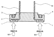
- FIG. 9 is a schematic cross-sectional view of the connector structure shown from a different viewpoint from FIG. 8 of the fifth embodiment of the present invention.
- the housing portion 2 includes three electrode portions 1 arranged at three locations and at least one seal member 3.
- the three electrode portions 1 are in direct contact with the three terminal portions 921 of the three-phase motor (in FIG. 9, two terminal portions 921 of the three terminal portions 921 are shown) and are loaded.
- the connector terminal portion 10 is electrically connected to the circuit board that controls the three-phase motor.
- the electrode portion 1 receives the load. It is possible to suppress deformation of the sealing surface 4 due to a load and ensure airtightness.
- Example 5 of the present invention the same effect as in Example 1 can be obtained.
- one housing portion 2 is provided with a three-phase electrode portion in which three electrode portions 1 are paired, and a plurality of three-phase electrode portions are formed in one housing portion 2. It is also possible to connect each of the three terminals of the three-phase motor.
- seal members 3 there are a plurality of seal members 3, and the seal members 3 are arranged for each of the three-phase electrode portions, and the three electrode portions 1 are plural with respect to the load direction received from the three terminal portions of the three-phase motor.
- Each of the seal members 3 of the above can be configured to be located directly above each of the three electrode portions 1. Even with such a configuration, it is possible to realize a highly integrated in-vehicle connector capable of suppressing deformation of the sealing surface due to a spring load and suppressing oil intrusion.
- the mounting position of the seal member 3 is set above the electrode portion 1 with respect to the load direction received by the electrode portion 1, and the method in the load direction received by the electrode portion 1 is performed.
- the relationship between the minimum distance dm in the linear direction and the width on the normal side in the compression direction in the circumferential direction of the annular seal member 3 with ds can be configured to satisfy dmin ⁇ ds --- .
- Example 6 of the present invention will be described.
- FIG. 10 is a schematic cross-sectional view of the connector structure and the power conversion device housing of the sixth embodiment of the present invention.
- the connector 40 has the connector structure of the first to fifth embodiments. Although the detailed shape is abbreviated, at least one connector 40 is mounted on the housing 50 of the power conversion device. The number and position of the connector 40 mounted depends on the actuator 80 having the actuator spring terminal (terminal portion) 81 electrically connected to the connector 40, or abbreviated as the number and position of the three-phase motor.
- the power conversion device includes (mounts) an actuator 80 or a drive circuit board 60 that controls a three-phase motor, and the drive circuit board 60 is electrically connected to the connector 40 by a connection portion 70.
- a connection portion 70 soldering, press fitting, caulking fixing and the like can be considered.
- the mounting location of the power conversion device may be, for example, an actuator 80 or a gearbox equipped with a three-phase motor, and may be considered as a partial function of a highly integrated e-axel system.
- FIG. 11 is a schematic configuration diagram of an example of a highly integrated e-axel system 100.
- the power conversion device 90 provided with the electronic control device (ATCU) 91 is mounted on a gearbox 93 equipped with a three-phase motor 92 or an actuator 80 (however, the actuator 80 is not shown in FIG. 11).
- the three-phase motor 92 or the actuator 80 mounted in the gearbox 93 is electrically connected to the drive circuit board 60 mounted on the power conversion device 90 by the connector 40.
- Example 6 of the present invention the same effect as in Example 1 can be obtained.
- the actuator 80 and the three-phase motor 92 can be collectively referred to as a drive unit.
- Electrode part, 2 ... Housing part, 3 ... Seal member, 4 ... Seal surface, 10 ... Connector terminal part, 11 ... Electrode part side surface part, 20 ... Fixed Part, 31 ... Seal member side surface, 40 ... Connector, 50 ... Power converter housing, 60 ... Drive circuit board, 70 ... Connection, 80 ... Actuator, 81 ... Actuator spring terminal, 90 ... Power converter, 91 ... Electronic control device, 92 ... Three-phase motor, 93 ... Gearbox, 100 ... Highly integrated e-axel System, 921 ... Terminal part of 3-phase motor
Landscapes
- Engineering & Computer Science (AREA)
- Power Engineering (AREA)
- Connector Housings Or Holding Contact Members (AREA)
Priority Applications (1)
| Application Number | Priority Date | Filing Date | Title |
|---|---|---|---|
| JP2022558930A JPWO2022091665A1 (https=) | 2020-10-29 | 2021-09-27 |
Applications Claiming Priority (2)
| Application Number | Priority Date | Filing Date | Title |
|---|---|---|---|
| JP2020181632 | 2020-10-29 | ||
| JP2020-181632 | 2020-10-29 |
Publications (1)
| Publication Number | Publication Date |
|---|---|
| WO2022091665A1 true WO2022091665A1 (ja) | 2022-05-05 |
Family
ID=81383978
Family Applications (1)
| Application Number | Title | Priority Date | Filing Date |
|---|---|---|---|
| PCT/JP2021/035322 Ceased WO2022091665A1 (ja) | 2020-10-29 | 2021-09-27 | 車載用コネクタ |
Country Status (2)
| Country | Link |
|---|---|
| JP (1) | JPWO2022091665A1 (https=) |
| WO (1) | WO2022091665A1 (https=) |
Citations (3)
| Publication number | Priority date | Publication date | Assignee | Title |
|---|---|---|---|---|
| WO2012056909A1 (ja) * | 2010-10-25 | 2012-05-03 | 矢崎総業株式会社 | 機器接続用コネクタ構造 |
| JP2015026568A (ja) * | 2013-07-29 | 2015-02-05 | 日本航空電子工業株式会社 | 電子機器モジュール |
| WO2018139515A1 (ja) * | 2017-01-30 | 2018-08-02 | 株式会社オートネットワーク技術研究所 | コネクタ |
-
2021
- 2021-09-27 JP JP2022558930A patent/JPWO2022091665A1/ja active Pending
- 2021-09-27 WO PCT/JP2021/035322 patent/WO2022091665A1/ja not_active Ceased
Patent Citations (3)
| Publication number | Priority date | Publication date | Assignee | Title |
|---|---|---|---|---|
| WO2012056909A1 (ja) * | 2010-10-25 | 2012-05-03 | 矢崎総業株式会社 | 機器接続用コネクタ構造 |
| JP2015026568A (ja) * | 2013-07-29 | 2015-02-05 | 日本航空電子工業株式会社 | 電子機器モジュール |
| WO2018139515A1 (ja) * | 2017-01-30 | 2018-08-02 | 株式会社オートネットワーク技術研究所 | コネクタ |
Also Published As
| Publication number | Publication date |
|---|---|
| JPWO2022091665A1 (https=) | 2022-05-05 |
Similar Documents
| Publication | Publication Date | Title |
|---|---|---|
| US10479398B2 (en) | Integrated electric power steering apparatus and manufacturing method therefor | |
| US10424991B2 (en) | Drive device | |
| EP2006987B1 (en) | Power converter device | |
| JP6562998B2 (ja) | 電力変換装置 | |
| US8403682B2 (en) | Electronic control device | |
| US10128722B2 (en) | Electrical connection structure, terminal structure, and vehicle | |
| US11956900B2 (en) | Electronic control unit and method for assembling electronic control unit | |
| US11011996B2 (en) | Power converter | |
| EP3525335B1 (en) | Capacitor unit, and electric compressor | |
| US11147163B2 (en) | Semiconductor module unit | |
| CN114628965A (zh) | 电动装置 | |
| JPWO2016117403A1 (ja) | 電力変換装置 | |
| WO2022091665A1 (ja) | 車載用コネクタ | |
| CN116033647A (zh) | 功率转换装置 | |
| WO2017204023A1 (ja) | 電力変換装置、及びその製造方法 | |
| US12021419B2 (en) | Electronic module and drive | |
| US10998670B2 (en) | Connection structure for power conversion device | |
| JP6818844B1 (ja) | 電力変換装置 | |
| CN114567186A (zh) | 功率转换装置及其制造方法 | |
| JP5784094B2 (ja) | 電子部品モジュールおよびその搭載方法 | |
| CN112260560A (zh) | 电力变换装置 | |
| US12564074B2 (en) | Power electronics module | |
| CN115088175B (zh) | 电力转换装置和电力转换装置的制造方法 | |
| CN121602184A (zh) | 导电连接组件及汽车 |
Legal Events
| Date | Code | Title | Description |
|---|---|---|---|
| 121 | Ep: the epo has been informed by wipo that ep was designated in this application |
Ref document number: 21885784 Country of ref document: EP Kind code of ref document: A1 |
|
| ENP | Entry into the national phase |
Ref document number: 2022558930 Country of ref document: JP Kind code of ref document: A |
|
| NENP | Non-entry into the national phase |
Ref country code: DE |
|
| 122 | Ep: pct application non-entry in european phase |
Ref document number: 21885784 Country of ref document: EP Kind code of ref document: A1 |