WO2022091376A1 - エレベーターの故障診断装置 - Google Patents
エレベーターの故障診断装置 Download PDFInfo
- Publication number
- WO2022091376A1 WO2022091376A1 PCT/JP2020/040929 JP2020040929W WO2022091376A1 WO 2022091376 A1 WO2022091376 A1 WO 2022091376A1 JP 2020040929 W JP2020040929 W JP 2020040929W WO 2022091376 A1 WO2022091376 A1 WO 2022091376A1
- Authority
- WO
- WIPO (PCT)
- Prior art keywords
- time
- structural
- model
- unit
- value
- Prior art date
- Legal status (The legal status is an assumption and is not a legal conclusion. Google has not performed a legal analysis and makes no representation as to the accuracy of the status listed.)
- Ceased
Links
Images




Classifications
-
- B—PERFORMING OPERATIONS; TRANSPORTING
- B66—HOISTING; LIFTING; HAULING
- B66B—ELEVATORS; ESCALATORS OR MOVING WALKWAYS
- B66B5/00—Applications of checking, fault-correcting, or safety devices in elevators
-
- G—PHYSICS
- G05—CONTROLLING; REGULATING
- G05B—CONTROL OR REGULATING SYSTEMS IN GENERAL; FUNCTIONAL ELEMENTS OF SUCH SYSTEMS; MONITORING OR TESTING ARRANGEMENTS FOR SUCH SYSTEMS OR ELEMENTS
- G05B23/00—Testing or monitoring of control systems or parts thereof
- G05B23/02—Electric testing or monitoring
Definitions
- This disclosure relates to an elevator failure diagnosis device.
- Patent Document 1 discloses an elevator failure diagnosis device.
- the failure diagnosis device diagnoses whether there is a sign of failure of the device based on how much the state quantity of the device to be diagnosed deviates from the distribution of the past state quantity.
- the failure diagnosis device described in Patent Document 1 diagnoses whether or not the device has a sign of failure by using a calculation model common to a plurality of devices. Therefore, the accuracy of diagnosing a sign that the device fails is reduced.
- An object of the present disclosure is to provide an elevator failure diagnostic device capable of improving the accuracy of detecting a sign of failure of the device.
- the elevator failure diagnosis device acquires information on a plurality of detected values detected by a detector attached to the device of the elevator for each device, and uses the plurality of detected values and a structural model to obtain the target device.
- a structural model unit that calculates the structural parameters of the structural model in the above, a time model unit that calculates the time parameters of the time model in the target device using the time model and the structural parameters calculated by the structural model unit, and a time model.
- the threshold creation unit that creates the threshold of the target device corresponding to the time parameter using the time parameter calculated in the unit, the structural parameter calculated in the structural model unit, and the time parameter calculated in the time model unit. It is provided with a sign diagnosis unit for diagnosing whether or not there is a sign that the target device fails by using either one and the threshold value created by the threshold creation unit.
- the sign diagnosis unit diagnoses whether there is a sign that the target device fails by using the threshold function corresponding to the time parameter of the time model in the target device. Therefore, it is possible to improve the accuracy of diagnosing a sign that the device fails.
- FIG. 1 It is a figure which shows the outline of the elevator system and the diagnosis system to which the failure diagnosis apparatus in Embodiment 1 is applied. It is a block diagram of the failure diagnosis apparatus in Embodiment 1.
- FIG. It is a graph which shows the transition of the time difference value of the speed command value detected by the drive device to which the failure diagnosis device in Embodiment 1 is applied for each activation. It is a graph which shows the transition of the value of the speed deviation detected in the drive device to which the failure diagnosis device in Embodiment 1 is applied for each activation. It is a graph which shows the transition of the value of the correction torque detected in the drive device to which the failure diagnosis device in Embodiment 1 is applied for each start.
- FIG. 1 is a diagram showing an outline of an elevator system and a diagnostic system to which the failure diagnosis device according to the first embodiment is applied.
- a plurality of elevator systems 1 are provided in each of a plurality of buildings 2.
- each of the plurality of elevator systems 1 has a similar configuration.
- the hoistway 3 penetrates each floor of the building 2.
- the machine room 4 is provided directly above the hoistway 3.
- Each of the plurality of landings 5 is provided on each floor of the building 2.
- Each of the plurality of landings 5 faces the hoistway 3.
- the plurality of landing doors 6 are provided at the entrances and exits of the plurality of landings 5.
- the drive device 7 is provided in the machine room 4.
- the main rope 8 is wound around the drive device 7.
- the car 9 is provided inside the hoistway 3.
- the basket 9 is hung on one side of the main rope 8.
- the balance weight 10 is provided inside the hoistway 3.
- the balance weight 10 is hung on the other side of the main rope 8.
- the plurality of detectors 11 are attached to the drive device 7.
- the control device 12 is provided in the machine room 4.
- the control device 12 is provided so as to be able to control the elevator as a whole.
- the monitoring device 13 is provided in the machine room 4.
- the monitoring device 13 is provided so as to be able to monitor the state of the elevator based on the information from the control device 12.
- the plurality of detectors 11 detect a plurality of detection values related to the operation of the drive device 7.
- the control device 12 rotates the drive device 7 based on a plurality of detection values from the plurality of detectors 11.
- the main rope 8 moves following the rotation of the drive device 7.
- the car 9 and the counterweight 10 follow the movement of the main rope 8 and move up and down in the hoistway 3 in opposite directions.
- the user moves between the car 9 and the landing 5 through the landing door 6.
- the information center 100 is provided at a location away from the building 2 in which the elevator system 1 is provided.
- the information center 100 is provided in an elevator maintenance company.
- the diagnostic system 50 is provided in the information center 100.
- the diagnostic system 50 includes a data storage device 20, a display device 21, a data collection device 22, and a failure diagnosis device 30.
- the data storage device 20 stores information.
- the display device 21 includes a display screen.
- the display screen displays information.
- the data collection device 22 collects information on a plurality of detected values from each of the plurality of monitoring devices 13.
- the plurality of detected values are values detected for each of the plurality of drive devices 7.
- Each of the plurality of detected values is a value detected at each activation.
- the activation is an operation from the start of the rotational movement of the drive device 7 to the stop of the rotational movement.
- the data collection device 22 stores information on a plurality of detected values in the data storage device 20.
- the failure diagnosis device 30 performs predictive diagnosis using information on a plurality of detected values of the data storage device 20.
- the failure diagnosis device 30 diagnoses whether or not a sign that the drive device fails is detected in the sign diagnosis.
- the failure diagnosis device 30 creates diagnostic information that is the result of the predictive diagnosis.
- the failure diagnosis device 30 causes the display device 21 to display the diagnosis information.
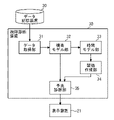
- FIG. 2 is a block diagram of the failure diagnosis device according to the first embodiment.
- the failure diagnosis device 30 includes a data acquisition unit 31, a structural model unit 32, a time model unit 33, a threshold value creation unit 34, and a predictive diagnosis unit 35.
- the data acquisition unit 31 acquires information on a plurality of detected values from the data storage device 20.
- the structural model unit 32 stores the information of the structural model.
- the structural model is a model that estimates the detected value of the drive device 7.
- a structural model is represented by a mathematical formula.
- the input is a plurality of first detection values as explanatory variables.
- the output is an estimate of the second detection value as the objective variable.
- the plurality of first detection values are some detection values selected from the plurality of detection values.
- the second detection value is one detection value selected from a plurality of detection values other than the plurality of first detection values.
- the structural model is constructed based on the characteristics between the plurality of first detected values and the second detected values in the drive device 7. Specifically, the characteristics are mechanical characteristics, electrical characteristics, control characteristics, and the like.
- the structural model unit 32 acquires information on a plurality of first detection values and second detection values from the data acquisition unit 31.
- the structural model unit 32 substitutes a plurality of first detected values and second detected values into the mathematical formula of the structural model and performs regression analysis.
- the structural model unit 32 calculates a plurality of types of structural parameters corresponding to one activation with respect to the target drive device 7.
- the structural model unit 32 stores the plurality of types of structural parameters as information on a set of structural parameters.
- the information of a set of structural parameters includes the information of the detection date and time.
- the detection date and time is the date and time when a plurality of detection values used for deriving the structural parameters are detected.
- the time model unit 33 stores information on a plurality of time models. Multiple time models correspond to each of the multiple types of structural parameters.
- the time model is a model that estimates the values of structural parameters of that type.
- the time model is represented by a mathematical formula.
- the input is the value of elapsed time as an explanatory variable.
- the elapsed time is the time from the reference date and time to the detection date and time.
- the reference date and time is arbitrarily set in advance.
- the output is a kind of structural parameter as an objective variable.
- the time model unit 33 acquires information on a plurality of structural parameters of the same type and different detection dates and times from the structural model unit 32.
- the time model unit 33 performs regression analysis by substituting the plurality of structural parameters of the type and the plurality of detection dates and times into the mathematical formula of the time model.
- the time model unit 33 calculates a set of time parameters corresponding to the structural parameters of the type in the regression analysis.
- a set of time parameters includes a plurality of types of time parameters.
- the threshold value creating unit 34 stores information on a plurality of time models that are the same as the plurality of time models stored in the time model unit 33.
- the threshold value creation unit 34 acquires information on a plurality of structural parameters of the same type and different detection dates and times and information on a set of time parameters from the time model unit 33.
- the threshold value creation unit 34 substitutes the time parameter into the mathematical formula of the time model.
- the threshold value creation unit 34 creates information on the variation value using a plurality of structural parameters of the same type and different detection dates and times as the time model.
- the variation value is a value indicating how much the values of a plurality of structural parameters vary with respect to the time model.
- the threshold value creation unit 34 creates a threshold value of a certain type of structural parameter using a time model and a variation value.
- the threshold value creation unit 34 creates a plurality of threshold values corresponding to each of the plurality of types of structural parameters.
- the predictive diagnosis unit 35 acquires information on a plurality of structural parameters of the same type and different detection dates and times from the structural model unit 32.
- the predictive diagnosis unit 35 acquires information on a plurality of threshold values from the threshold value creation unit 34.
- the predictive diagnosis unit 35 stores information on a plurality of threshold values.
- the predictive diagnosis unit 35 performs predictive diagnosis for each of a plurality of structural parameters of the same type and different detection dates and times.
- the predictive diagnostic unit 35 compares the values of certain structural parameters with the corresponding thresholds.
- the predictive diagnosis unit 35 determines whether or not the structural parameter is abnormal by comparing with the threshold value.
- the predictive diagnosis unit 35 determines whether or not the number of structural parameters determined to be abnormal is larger than the specified number for a plurality of structural parameters of the same type and different detection dates and times. When the number of structural parameters determined to be abnormal is greater than the specified number, the predictive diagnostic unit 35 diagnoses that the target drive device 7 related to the structural parameter has a sign of failure. When the number of structural parameters determined to be abnormal is less than or equal to the specified number, the sign diagnosis unit 35 diagnoses that the target drive device 7 related to the structural parameter has no sign of failure.
- the predictive diagnosis unit 35 performs predictive diagnosis regarding all types of structural parameters calculated by the structural model unit 32.
- the predictive diagnosis unit 35 creates diagnostic information including the result of the predictive diagnosis regarding the drive device 7 of the target.
- the predictive diagnosis unit 35 causes the display device 21 to display the diagnostic information.
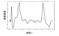
- FIG. 3 is a graph showing the transition of the time difference value of the speed command value detected by the drive device to which the failure diagnosis device in the first embodiment is applied for each activation.
- the horizontal axis of the graph is the time elapsed since the drive device 7 started the rotational movement.
- the vertical axis of the graph is the value of the time difference of the speed command value with respect to the drive device 7.
- the speed command value is a command value of the drive speed for the drive device 7.
- the value of the time difference of the speed command value is a value obtained by differentiating the speed command value with respect to time.
- FIG. 4 is a graph showing the transition of the value of the speed deviation detected by the drive device to which the failure diagnosis device in the first embodiment is applied for each activation.
- the horizontal axis of the graph is the time elapsed since the drive device 7 started the rotational movement.
- the vertical axis of the graph is the value of the speed deviation of the drive device 7.
- the value of the speed deviation is the difference between the command value of the driving speed and the value of the actual speed.
- FIG. 5 is a graph showing the transition of the correction torque value detected by the drive device to which the failure diagnosis device according to the first embodiment is applied for each activation.
- the horizontal axis of the graph is the time elapsed since the drive device 7 started the rotational movement.
- the vertical axis of the graph is the value of the correction torque given to the drive device 7.
- the correction torque is the torque given to the drive device 7 to control the operation.
- FIG. 6 is a graph showing the transition of the value of the q-axis current detected by the drive device to which the failure diagnosis device according to the first embodiment is applied for each activation.
- the horizontal axis of the graph is the time elapsed since the drive device 7 started the rotational movement.
- the vertical axis of the graph is the value of the q-axis current in the drive device 7.
- the transition of the value of the q-axis current is shown by a solid line.
- the structural model is expressed by the following equation (1).
- the structural parameters are a, b, c, and d.
- the objective variable is the value q (t) of the q-axis current of the drive device 7.
- the explanatory variables are the time difference value d ⁇ sw (t) ⁇ / dt of the speed command value, the speed deviation value vd (t), and the correction torque value fa (t).
- the structural model unit 32 formulates the q-axis current value, the time difference value of the speed command value, the speed deviation value, and the correction torque value in one start as shown in FIGS. 3 to 6 (1). Perform regression analysis assigned to.
- the structural model unit 32 calculates a set of structural parameters a, b, c, and d by the regression analysis.
- the estimated value of the q-axis current is calculated from the time difference value of the speed command value, the speed deviation value, and the correction torque value.
- the transition of the estimated value of the q-axis current is shown by a broken line.
- FIG. 7 is a graph showing an example of a time model stored in the failure diagnosis device according to the first embodiment.
- the horizontal axis of the graph is the elapsed time.
- the vertical axis of the graph is the value of the structural parameter a.
- the points plotted on the graph represent the relationship between the value of the structural parameter a and the detection date and time.
- the graph shows a plurality of structural parameters a having different detection dates and times.
- the time model is expressed by the following equation (2).
- the time parameters are p, q, r, s.
- the objective variable is the structural parameter a (t') at a certain elapsed time.
- the explanatory variable is the elapsed time t'.
- sin (t'+ q) represents a characteristic in which the structural parameter a changes periodically with respect to the elapsed time. Specifically, sin (t'+ q) represents a seasonal change in the structural parameter a. In this case, for example, q is a value corresponding to 12 months.
- ⁇ (t') is a function representing the characteristic that the structural parameter a changes monotonically with respect to the elapsed time. Specifically, ⁇ (t') represents a change in the value of a due to aged deterioration.
- ⁇ (t') is a function that linearly combines the powers of t', a logarithmic function of t', an exponential function of t', or a function that combines these functions.
- ⁇ (t') is a function representing the influence of the motion condition for each activation on the structural parameter a. Specifically, ⁇ (t') represents the effect of the starting weight of the car 9 on the value of a.
- the time model unit 33 performs regression analysis by substituting a plurality of structural parameters a having different detection dates and times and the detection date and time into the equation (2).
- the time model unit 33 calculates a set of time parameters p, q, r, and s by the regression analysis.
- the set of time parameters corresponds to the structural parameter a.
- the time model to which a set of time parameters is assigned is represented by a curve.
- the time model unit 33 creates information on the application period corresponding to a set of time parameters.
- the application period is the period from the oldest date and time to the latest date and time among the plurality of detection dates and times applied when calculating a set of time parameters.
- the applicable period is the period from November 2017 to October 2018.
- FIG. 8 is a graph showing an example of a threshold value created by the failure diagnosis device according to the first embodiment.
- the horizontal axis of the graph is the elapsed time t'.
- the vertical axis of the graph is the value of the structural parameter a.
- a time model with a set of time parameters assigned is represented by a solid curve.
- the threshold value creating unit 34 stores information of the time model represented by the equation (2) in advance.
- the threshold value creating unit 34 acquires information on a plurality of structural parameters a having different detection dates and times and information on a set of time parameters corresponding to the structural parameters a from the time model unit 33.
- the threshold value creation unit 34 substitutes a set of time parameters into the time model.
- the threshold value creating unit 34 obtains the residual of each of the plurality of structural parameters a with respect to the time model.
- the threshold value creating unit 34 calculates the value of the standard deviation regarding the residual as the variation value ⁇ using the plurality of calculated residuals.
- the threshold value creation unit 34 calculates the upper limit threshold value function corresponding to the structural parameter a by using the variation value ⁇ and the time model.
- the upper threshold function is a function obtained by adding a value obtained by multiplying the variation value ⁇ by n to the time model.
- n is a positive number.
- the upper threshold function is a function of the elapsed time t'. In FIG. 8, the upper threshold function is represented by a broken line curve A.
- the threshold value creation unit 34 calculates the lower limit threshold value function corresponding to the structural parameter a by using the variation value ⁇ and the time model.
- the lower limit threshold function is a function obtained by subtracting the value obtained by multiplying the variation value ⁇ by n from the time model.
- n is a positive number.
- the lower threshold function is a function of the elapsed time t'. In FIG. 8, the lower threshold function is represented by a broken line curve B.
- the predictive diagnosis unit 35 determines that the structural parameter a is normal. For example, the predictive diagnosis unit 35 determines that the structural parameter a represented by the triangular plot of FIG. 8 is normal. When the value of the structural parameter a does not exist between the curve of the upper limit threshold function and the curve of the lower limit threshold function, the predictive diagnosis unit 35 determines that the structural parameter a is abnormal. For example, the sign diagnosis unit 35 determines that the structural parameter a represented by the quadrangular plot of FIG. 8 is abnormal.
- FIG. 9 is a flowchart for explaining the operation of the sign diagnosis performed by the failure diagnosis device according to the first embodiment.
- the failure diagnosis device 30 performs a predictive diagnosis operation at predetermined intervals.
- step S001 the data acquisition unit 31 acquires information on a plurality of detected values of the target drive device 7 among the plurality of drive devices 7 from the data storage device 20.
- step S002 the structural model unit 32 calculates the structural parameters related to the target drive device 7.
- step S003 the time model unit 33 calculates a time parameter corresponding to a certain type of structural parameter.
- step S004 the threshold value creation unit 34 creates a threshold value.
- step S005 the predictive diagnosis unit 35 acquires information on a plurality of structural parameters of the same type and different detection dates and times from the structural model unit 32.
- the sign diagnosis unit 35 acquires the threshold information.
- step S006 the predictive diagnosis unit 35 performs predictive diagnosis for a plurality of structural parameters of the same type and different detection dates and times.
- step S007 the predictive diagnosis unit 35 determines whether or not the predictive diagnosis has been performed for all types of structural parameters.
- step S007 If there is a type of structural parameter for which the predictive diagnosis has not been performed in step S007, the operations after step S003 are performed.
- step S007 If the predictive diagnosis is performed for all types of structural parameters in step S007, the operation of step S008 is performed.
- step S008 the predictive diagnosis unit 35 causes the display device 21 to display the diagnostic information.
- the failure diagnosis device 30 ends the operation of the sign diagnosis.
- the failure diagnosis device 30 calculates the time parameter corresponding to the target drive device 7.
- the failure diagnosis device 30 creates a threshold value corresponding to the target drive device 7.
- the failure diagnosis device 30 diagnoses whether there is a sign that the target drive device 7 fails. Therefore, when performing a predictive diagnosis, it is possible to use a time model that takes into consideration the situation such as the installation environment that differs for each drive device 7. As a result, the accuracy of diagnosing the sign of failure of the device can be improved.
- the failure diagnosis device 30 stores the information of the structural model. Therefore, if it is diagnosed that there is a sign of failure, the structural parameters diagnosed as having an abnormality are likely to be related to the mechanical or electrical abnormality of the drive device 7. As a result, the cause of the sign of the failure can be easily estimated.
- the failure diagnosis device 30 calculates structural parameters using a plurality of detected values detected at each start-up. Therefore, the failure diagnosis device 30 can use a structural model based on actual control. As a result, the accuracy of regression analysis for calculating structural parameters can be improved.
- the failure diagnosis device 30 stores the information of the time model. Therefore, the relationship between the mechanical or electrical characteristics of the drive device 7 and the elapsed time can be derived.
- the failure diagnosis device 30 stores a time model having a term that reflects the characteristic that the structural parameter changes periodically due to the change of seasons. Therefore, it is possible to perform a predictive diagnosis that reflects changes in the seasons. As a result, the accuracy of predictive diagnosis can be improved.
- the time model of the failure diagnosis device 30 stores a time model having a term that reflects the characteristic that the structural parameters change monotonically with the passage of time. Therefore, it is possible to perform a predictive diagnosis that reflects deterioration, wear, and the like of the drive device 7.
- the failure diagnosis device 30 creates a threshold value of the structural parameter using the time parameter.
- the failure diagnosis device 30 makes a predictive diagnosis using the values of the structural parameters. Therefore, the predictive diagnosis can be performed using the structural parameter based on the actually detected detection value and the threshold value reflecting the time change of the structural parameter. As a result, the accuracy of the predictive diagnosis can be improved as compared with the diagnostic method using only the actually detected values.
- the failure diagnosis device 30 calculates the variation value.
- the failure diagnosis device 30 creates a threshold function using the variation value. Therefore, the predictive diagnosis can be performed using the threshold value in consideration of the variation generated in the actual drive device 7.
- a plurality of elevator systems 1 may be provided in the building 2.
- the detector 11 may detect the value of the tachometer, the weighed value of the car 9, the temperature of the machine room 4, and the like.
- the failure diagnosis device 30 may perform a predictive diagnosis using the value of the tachometer, the weighed value of the car 9, the temperature of the machine room 4, and the like.
- the failure diagnosis device 30 may be applied to an elevator device other than the drive device 7. In this case, the failure diagnosis device 30 stores information on the structural model and the time model corresponding to the target device.
- the failure diagnosis device 30 may perform a predictive diagnosis at any timing. For example, the maintenance personnel may periodically send a command to execute the predictive diagnosis to the failure diagnosis device 30. In this case, the failure diagnosis device 30 performs the predictive diagnosis when it receives a command to execute the predictive diagnosis.
- the mathematical formula of the structural model may be based on already known physical characteristics, electrical characteristics, and the like. For example, when constructing a structural model for a machine in which output signals are obtained from a plurality of input signals, the output signals may be set as objective variables. In this case, a plurality of input signals may be set as a plurality of explanatory variables.
- the structural model unit 32 may store information on a plurality of structural models.
- the structural model unit 32 may select a structural model suitable for the operating state of the drive device 7. For example, in the elevator system 1, when an operation pattern corresponding to the total weight of the car 9 is selected from a plurality of operation patterns, the structural model unit 32 stores information of a plurality of structural models corresponding to the plurality of operation patterns. do it. In this case, the structural model unit 32 may acquire information on the selected operation pattern.
- the structural model unit 32 may calculate a set of structural parameters according to the operation pattern.
- the structural model unit 32 may specify an operation pattern by classifying a plurality of detected values.
- the structural model unit 32 may classify a plurality of detected values by using a statistical method such as clustering.
- the structural model unit 32 may specify the selected operation pattern by classifying a plurality of detected values.
- the formula of the time model may represent the change of the structural parameter with respect to the elapsed time.
- the mathematical formula of the time model may be a mathematical formula in which the term uT (t') is added to the right side of the equation (2).
- T (t') represents the temperature of the machine room 4.
- u is a time parameter.
- the threshold value creating unit 34 may select a structural parameter to be used when calculating the variation value ⁇ . For example, the threshold value creating unit 34 may select a structural parameter having a detection date and time within a period of 3 days from the date and time when the target drive device 7 is maintained and inspected.
- the threshold value creation unit 34 may create a threshold value by using a general statistical method such as Mahalanobis distance.
- the operation of the threshold value creating unit 34 may be performed by the time model unit 33.
- the time model unit 33 may create the threshold value by performing the same operation as the threshold value creation unit 34.
- the predictive diagnosis unit 35 may acquire threshold information from the time model unit 33.
- the display device 21 may notify the maintenance staff in the information center 100 to that effect.
- the display device 21 may transmit the diagnostic information to the corresponding monitoring device 13. In this case, the monitoring device 13 may notify the user of the drive device 7 diagnosed as having a sign of failure.
- FIG. 10 is a graph showing a modified example of the threshold value created by the failure diagnosis device in the first embodiment.
- the horizontal axis of the graph is the elapsed time.
- the vertical axis of the graph is the value of the structural parameter a.
- the two dashed lines shown in the graph represent examples of the upper threshold function A and the lower threshold function B, respectively.
- the predictive diagnosis unit 35 compares the structural parameter a in the prediction period with the upper limit threshold function and the lower limit threshold function.
- the forecast period is a period after the applicable period.
- the sign diagnosis unit 35 determines that the structural parameter a represented by the quadrangular plot of FIG. 10 is abnormal. In this case, the sign diagnosis unit 35 diagnoses that the drive device 7 related to the structural parameter a has a sign of failure.
- the failure diagnosis device 30 determines an abnormality in the structural parameters during the period other than the application period. In this case, the failure diagnosis device 30 performs the predictive diagnosis regarding the drive device 7 without performing the calculation of the time parameter. Therefore, the failure diagnosis device 30 can increase the frequency of predictive diagnosis.
- FIG. 11 is a hardware configuration diagram of the failure diagnosis device according to the first embodiment.
- Each function of the failure diagnosis device 30 can be realized by a processing circuit.
- the processing circuit comprises at least one processor 200a and at least one memory 200b.
- the processing circuit comprises at least one dedicated hardware 300.
- each function of the failure diagnosis device 30 is realized by software, firmware, or a combination of software and firmware. At least one of the software and firmware is written as a program. At least one of the software and firmware is stored in at least one memory 200b. At least one processor 200a realizes each function of the failure diagnosis device 30 by reading and executing a program stored in at least one memory 200b. At least one processor 200a is also referred to as a central processing unit, a processing unit, an arithmetic unit, a microprocessor, a microcomputer, and a DSP.
- At least one memory 200b is a non-volatile or volatile semiconductor memory such as RAM, ROM, flash memory, EPROM, EEPROM, a magnetic disk, a flexible disk, an optical disk, a compact disk, a mini disk, a DVD, or the like.
- the processing circuit comprises at least one dedicated hardware 300
- the processing circuit may be implemented, for example, as a single circuit, a composite circuit, a programmed processor, a parallel programmed processor, an ASIC, an FPGA, or a combination thereof. ..
- each function of the failure diagnosis device 30 is realized by a processing circuit.
- each function of the failure diagnosis device 30 is collectively realized by a processing circuit.
- a part may be realized by the dedicated hardware 300, and the other part may be realized by software or firmware.
- the function of the structural model unit 32 is realized by a processing circuit as dedicated hardware 300, and the function other than the function of the structural model unit 32 is a program in which at least one processor 200a is stored in at least one memory 200b. It may be realized by reading and executing.
- the processing circuit realizes each function of the failure diagnosis device 30 by the hardware 300, the software, the firmware, or a combination thereof.
- each function of the data acquisition device 22 is also realized by a processing circuit equivalent to a processing circuit that realizes each function of the failure diagnosis device 30.
- Each function of the data storage device 20 is also realized by a processing circuit equivalent to a processing circuit that realizes each function of the failure diagnosis device 30.
- FIG. 12 is a block diagram of the failure diagnosis device according to the second embodiment.
- the same or corresponding parts as those of the first embodiment are designated by the same reference numerals. The explanation of this part is omitted.
- the threshold value creation unit 34 acquires information on a set of time parameters from the time model unit 33.
- the threshold value creation unit 34 creates a threshold value for each of the plurality of time parameters included in the set of time parameters. For example, the threshold value creating unit 34 uses a value obtained by adding a constant value to the acquired time parameter value as the threshold value.
- the sign diagnosis unit 35 acquires threshold information about the time parameter from the threshold creation unit 34.
- the predictive diagnosis unit 35 stores the information of the threshold value.
- the predictive diagnosis unit 35 acquires information on a plurality of time parameters from the time model unit 33.
- the predictive diagnosis unit 35 compares a plurality of time parameters with a plurality of corresponding threshold values.
- the predictive diagnosis unit 35 determines whether or not each of the plurality of time parameters is abnormal by comparing with the threshold value.
- the sign diagnosis unit 35 diagnoses that the target drive device 7 related to the time parameter has no sign of failure.
- the sign diagnosis unit 35 diagnoses that the target drive device 7 related to the time parameter has a sign of failure.
- the predictive diagnosis unit 35 determines whether or not each of the plurality of types of time parameters is abnormal.
- the predictive diagnosis unit 35 determines whether or not each of the plurality of time parameters corresponding to the plurality of types of structural parameters is abnormal.
- the failure diagnosis device 30 creates a threshold value of the time parameter.
- the failure diagnosis device 30 performs predictive diagnosis by comparing the value of the time parameter with the threshold value.
- the values of the time parameters reflect changes in structural parameters over time. Therefore, it is possible to detect signs of failure caused by long-term changes.
- the threshold value created by the threshold value creation unit 34 is not limited to the threshold value described in the second embodiment.
- the elevator failure diagnosis device can be used for the elevator system.
Landscapes
- Physics & Mathematics (AREA)
- General Physics & Mathematics (AREA)
- Engineering & Computer Science (AREA)
- Automation & Control Theory (AREA)
- Indicating And Signalling Devices For Elevators (AREA)
- Maintenance And Inspection Apparatuses For Elevators (AREA)
- Testing And Monitoring For Control Systems (AREA)
Priority Applications (3)
| Application Number | Priority Date | Filing Date | Title |
|---|---|---|---|
| CN202080106615.6A CN116348406B (zh) | 2020-10-30 | 2020-10-30 | 电梯的故障诊断装置 |
| PCT/JP2020/040929 WO2022091376A1 (ja) | 2020-10-30 | 2020-10-30 | エレベーターの故障診断装置 |
| JP2022558778A JP7226671B2 (ja) | 2020-10-30 | 2020-10-30 | エレベーターの故障診断装置 |
Applications Claiming Priority (1)
| Application Number | Priority Date | Filing Date | Title |
|---|---|---|---|
| PCT/JP2020/040929 WO2022091376A1 (ja) | 2020-10-30 | 2020-10-30 | エレベーターの故障診断装置 |
Publications (1)
| Publication Number | Publication Date |
|---|---|
| WO2022091376A1 true WO2022091376A1 (ja) | 2022-05-05 |
Family
ID=81383877
Family Applications (1)
| Application Number | Title | Priority Date | Filing Date |
|---|---|---|---|
| PCT/JP2020/040929 Ceased WO2022091376A1 (ja) | 2020-10-30 | 2020-10-30 | エレベーターの故障診断装置 |
Country Status (3)
| Country | Link |
|---|---|
| JP (1) | JP7226671B2 (https=) |
| CN (1) | CN116348406B (https=) |
| WO (1) | WO2022091376A1 (https=) |
Cited By (3)
| Publication number | Priority date | Publication date | Assignee | Title |
|---|---|---|---|---|
| CN116281476A (zh) * | 2023-03-01 | 2023-06-23 | 深圳市卓越信息技术有限公司 | 一种基于ar和人工智能的电梯预防性维保方法和系统 |
| WO2024084684A1 (ja) * | 2022-10-21 | 2024-04-25 | 三菱電機ビルソリューションズ株式会社 | エレベーターの診断システムおよび診断方法 |
| JP2024170793A (ja) * | 2023-05-29 | 2024-12-11 | 東芝エネルギーシステムズ株式会社 | 回転電機管理システム |
Citations (2)
| Publication number | Priority date | Publication date | Assignee | Title |
|---|---|---|---|---|
| JP2019503002A (ja) * | 2015-12-22 | 2019-01-31 | ビーダブリューエックスティー エムパワー、インコーポレイテッド | データ駆動型ワークフローによる安全解析評価装置及びシステム安全解析評価方法 |
| JP2019096247A (ja) * | 2017-11-28 | 2019-06-20 | 株式会社日立製作所 | 故障モード特定システム、故障モード特定方法、及びプログラム |
Family Cites Families (5)
| Publication number | Priority date | Publication date | Assignee | Title |
|---|---|---|---|---|
| CN104076809B (zh) * | 2013-03-26 | 2017-01-04 | 三菱电机株式会社 | 数据处理装置以及数据处理方法 |
| US11548758B2 (en) * | 2017-06-30 | 2023-01-10 | Otis Elevator Company | Health monitoring systems and methods for elevator systems |
| CN108529380B (zh) * | 2018-03-27 | 2021-01-19 | 深圳市永达电子信息股份有限公司 | 电梯安全预测方法及系统 |
| CN108584592B (zh) * | 2018-05-11 | 2019-10-11 | 浙江工业大学 | 一种基于时间序列预测模型的电梯轿厢振动异常预警方法 |
| CN109896383B (zh) * | 2019-01-18 | 2020-07-07 | 西人马帝言(北京)科技有限公司 | 电梯故障诊断方法、装置、设备及计算机存储介质 |
-
2020
- 2020-10-30 WO PCT/JP2020/040929 patent/WO2022091376A1/ja not_active Ceased
- 2020-10-30 CN CN202080106615.6A patent/CN116348406B/zh active Active
- 2020-10-30 JP JP2022558778A patent/JP7226671B2/ja active Active
Patent Citations (2)
| Publication number | Priority date | Publication date | Assignee | Title |
|---|---|---|---|---|
| JP2019503002A (ja) * | 2015-12-22 | 2019-01-31 | ビーダブリューエックスティー エムパワー、インコーポレイテッド | データ駆動型ワークフローによる安全解析評価装置及びシステム安全解析評価方法 |
| JP2019096247A (ja) * | 2017-11-28 | 2019-06-20 | 株式会社日立製作所 | 故障モード特定システム、故障モード特定方法、及びプログラム |
Cited By (3)
| Publication number | Priority date | Publication date | Assignee | Title |
|---|---|---|---|---|
| WO2024084684A1 (ja) * | 2022-10-21 | 2024-04-25 | 三菱電機ビルソリューションズ株式会社 | エレベーターの診断システムおよび診断方法 |
| CN116281476A (zh) * | 2023-03-01 | 2023-06-23 | 深圳市卓越信息技术有限公司 | 一种基于ar和人工智能的电梯预防性维保方法和系统 |
| JP2024170793A (ja) * | 2023-05-29 | 2024-12-11 | 東芝エネルギーシステムズ株式会社 | 回転電機管理システム |
Also Published As
| Publication number | Publication date |
|---|---|
| JP7226671B2 (ja) | 2023-02-21 |
| CN116348406A (zh) | 2023-06-27 |
| CN116348406B (zh) | 2024-03-08 |
| JPWO2022091376A1 (https=) | 2022-05-05 |
Similar Documents
| Publication | Publication Date | Title |
|---|---|---|
| JP6810097B2 (ja) | 異常検出器 | |
| KR101880353B1 (ko) | 엘리베이터의 고장 예측 시스템 | |
| KR102546093B1 (ko) | 엘리베이터의 브레이크 장치 열화 예측 시스템 | |
| JP7226671B2 (ja) | エレベーターの故障診断装置 | |
| EP2562614A2 (en) | Control device of control system and elevator systems | |
| JP2009053938A (ja) | 複数モデルに基づく設備診断システム及びその設備診断方法 | |
| CN111386540B (zh) | 维护计划系统和维护计划方法 | |
| KR102509840B1 (ko) | 엘리베이터의 브레이크 장치 이상 진단 시스템 | |
| JP2008230742A (ja) | エレベータの保守管理システム | |
| CN119349367A (zh) | 一种基于电梯实时运行状态的故障预测方法、设备及介质 | |
| US12169791B2 (en) | Model development framework for remote monitoring condition-based maintenance | |
| JP6565781B2 (ja) | エレベーターの戸開閉診断システム | |
| JP6673737B2 (ja) | システム機器の異常診断装置、エレベーターの異常診断装置及びエレベーターの異常診断方法 | |
| CN112119027B (zh) | 用于检测电梯中的故障的方法和电梯控制器 | |
| JP7030073B2 (ja) | エレベーターおよびブレーキ診断方法 | |
| US20220403690A1 (en) | Method for determining and/or verifying a status of a door system, status determination device, system, computer program product | |
| EP4582366A1 (en) | Elevator maintenance system | |
| CN116040427A (zh) | 电梯异常检测系统和方法 | |
| WO2024084684A1 (ja) | エレベーターの診断システムおよび診断方法 | |
| JP2025155151A (ja) | 制御装置 | |
| CN121536793A (zh) | 电梯安全预警方法、系统、设备及介质 | |
| HK40033792B (en) | Method and elevator controller for detecting a malfunction in an elevator | |
| HK40033792A (en) | Method and elevator controller for detecting a malfunction in an elevator | |
| HK40044317B (en) | Elevator brake device deterioration prediction system |
Legal Events
| Date | Code | Title | Description |
|---|---|---|---|
| 121 | Ep: the epo has been informed by wipo that ep was designated in this application |
Ref document number: 20959893 Country of ref document: EP Kind code of ref document: A1 |
|
| ENP | Entry into the national phase |
Ref document number: 2022558778 Country of ref document: JP Kind code of ref document: A |
|
| NENP | Non-entry into the national phase |
Ref country code: DE |
|
| 122 | Ep: pct application non-entry in european phase |
Ref document number: 20959893 Country of ref document: EP Kind code of ref document: A1 |