WO2022085583A1 - タイヤ摩耗測定装置、空気入りタイヤおよびタイヤ摩耗測定方法 - Google Patents
タイヤ摩耗測定装置、空気入りタイヤおよびタイヤ摩耗測定方法 Download PDFInfo
- Publication number
- WO2022085583A1 WO2022085583A1 PCT/JP2021/038211 JP2021038211W WO2022085583A1 WO 2022085583 A1 WO2022085583 A1 WO 2022085583A1 JP 2021038211 W JP2021038211 W JP 2021038211W WO 2022085583 A1 WO2022085583 A1 WO 2022085583A1
- Authority
- WO
- WIPO (PCT)
- Prior art keywords
- magnetic
- tire
- sensor
- wear
- magnetic material
- Prior art date
- Legal status (The legal status is an assumption and is not a legal conclusion. Google has not performed a legal analysis and makes no representation as to the accuracy of the status listed.)
- Ceased
Links
Images



Classifications
-
- B—PERFORMING OPERATIONS; TRANSPORTING
- B60—VEHICLES IN GENERAL
- B60C—VEHICLE TYRES; TYRE INFLATION; TYRE CHANGING; CONNECTING VALVES TO INFLATABLE ELASTIC BODIES IN GENERAL; DEVICES OR ARRANGEMENTS RELATED TO TYRES
- B60C11/00—Tyre tread bands; Tread patterns; Anti-skid inserts
- B60C11/24—Wear-indicating arrangements
-
- B—PERFORMING OPERATIONS; TRANSPORTING
- B60—VEHICLES IN GENERAL
- B60C—VEHICLE TYRES; TYRE INFLATION; TYRE CHANGING; CONNECTING VALVES TO INFLATABLE ELASTIC BODIES IN GENERAL; DEVICES OR ARRANGEMENTS RELATED TO TYRES
- B60C19/00—Tyre parts or constructions not otherwise provided for
-
- G—PHYSICS
- G01—MEASURING; TESTING
- G01B—MEASURING LENGTH, THICKNESS OR SIMILAR LINEAR DIMENSIONS; MEASURING ANGLES; MEASURING AREAS; MEASURING IRREGULARITIES OF SURFACES OR CONTOURS
- G01B7/00—Measuring arrangements characterised by the use of electric or magnetic techniques
-
- G—PHYSICS
- G01—MEASURING; TESTING
- G01B—MEASURING LENGTH, THICKNESS OR SIMILAR LINEAR DIMENSIONS; MEASURING ANGLES; MEASURING AREAS; MEASURING IRREGULARITIES OF SURFACES OR CONTOURS
- G01B7/00—Measuring arrangements characterised by the use of electric or magnetic techniques
- G01B7/02—Measuring arrangements characterised by the use of electric or magnetic techniques for measuring length, width or thickness
- G01B7/06—Measuring arrangements characterised by the use of electric or magnetic techniques for measuring length, width or thickness for measuring thickness
-
- G—PHYSICS
- G01—MEASURING; TESTING
- G01M—TESTING STATIC OR DYNAMIC BALANCE OF MACHINES OR STRUCTURES; TESTING OF STRUCTURES OR APPARATUS, NOT OTHERWISE PROVIDED FOR
- G01M17/00—Testing of vehicles
- G01M17/007—Wheeled or endless-tracked vehicles
- G01M17/02—Tyres
Definitions
- the present invention relates to a tire wear measuring device for detecting wear of a tread portion based on a magnetic field of a magnetic material embedded in a pneumatic tire, a pneumatic tire, and a tire wear measuring method.
- a pneumatic tire (hereinafter, also referred to as a tire as appropriate) wears, the grip performance when traveling on a road surface and the drainage that drains water between the tire and the road surface when traveling on a wet road surface. Performance is reduced. Therefore, the driver or the vehicle manager visually inspects the wear state of the tread of the tire and replaces the tire before the usage limit is exceeded in order to ensure safety. For visual inspection, slip signs provided in the tire grooves are used. However, the inspection work is complicated, and there is a possibility that the evaluation of the wear state may be erroneous. It is possible that some users will not perform the inspection. If the evaluation is incorrect, the tire with deteriorated performance will continue to be used, which is not preferable from the viewpoint of safety.
- Patent Document 1 has a magnetic sensor that detects the magnetic flux density of the magnetic field in the tire radial direction of the tread portion, and is configured to measure the wear of the tread portion by the magnetic flux density detected by the magnetic sensor. A wear measurement system is described.
- Patent Document 1 The system described in Patent Document 1 is embedded in the tread portion of a tire and detects the wear of the tread portion from the change of the magnetic field generated by the magnetic material that wears together with the tread portion.
- the magnetic flux density of the magnetic field generated by the magnetic material changes linearly with the wear of the magnetic material, that is, the amount of wear of the magnetic material and the amount of change in the magnetic flux density. Good linearity is preferable.
- the present invention includes a magnetic material embedded in the tread portion and worn due to wear of the tread portion, and a magnetic sensor arranged at a position facing the magnetic body of the tire.
- the magnetic sensor is the magnetic material.
- a tire wear measuring device that detects a change in the magnetic flux density of the magnetic field formed by the above, the bottom surface of the magnetic material appears on the ground contact surface of the tread portion, and the area of the bottom surface becomes smaller as the tread portion wears.
- the shape of the magnetic material is preferably a frustum, more preferably a frustum.
- the magnetic material as a weight base, the area of the bottom surface appearing on the ground plane of the tread portion changes continuously and smoothly as the tread portion wears. Therefore, the linearity between the amount of wear of the magnetic material and the amount of change in the magnetic flux density is improved.
- a frustum whose end opposite to the bottom surface of the magnetic material is a flat surface (upper surface), it is possible to prevent damage to a part of the magnetic material when it is embedded in the tread portion, and the magnetism is easily and stably performed. You can bury your body.
- the shape of the magnetic material is a truncated cone with smooth sides, it is possible to reduce variations in the detected magnetic field due to the influence of positional deviation from the magnetic sensor placed inside the tire.
- the magnetic material can be embedded in the tread portion more smoothly.
- the magnetic sensor has a first sensor and a second sensor, and when viewed in a plan view from the radial direction of the tire, the first sensor is arranged on one side and the other side sandwiches the magnetic body.
- the second sensor may be arranged, and the wear of the tread portion may be detected based on the output of the first sensor and the output of the second sensor.
- the direction of the magnetic field is opposite on one side and the other side of the magnetic material. Therefore, by using the difference between the output of the first sensor and the output of the second sensor, it is possible to obtain a larger output than one magnetic sensor. Further, since the influence of noise such as an external magnetic field extends equally to the first sensor and the second sensor, noise can be suppressed by using the difference between the two outputs.
- the magnetic material connects the first sensor and the second sensor when viewed in a plan view from the radial direction of the tire. It is preferably located on a straight line, and the distance from the center of the magnetic material to the first sensor is equal to the distance from the center of the magnetic material to the second sensor.
- the magnitudes of the magnetic flux densities of the magnetic fields in opposite directions detected by the first sensor and the second sensor are about the same. Therefore, since the amount of wear of the magnetic material can be detected based on only one of the outputs, the redundancy of the magnetic sensor is improved.
- the present invention comprises the tire wear measuring device of the present invention, and the magnetic material is formed by dispersing and forming powders and granules of a hard magnetic material in a polymer material and magnetizing the magnetic material in one direction.
- a pneumatic tire characterized by being embedded in the tread portion so that the magnetizing direction and the tire radial direction coincide with each other.
- the present invention is a tire wear measuring method for measuring a tire wear state by the tire wear measuring device of the present invention, in which the magnetic flux density of a magnetic field changed by the wear of the magnetic material is measured and measured by the magnetic sensor.
- a tire wear measuring method characterized by measuring a wear state of the tread portion of the tire based on a change in the magnetic flux density.
- the amount of wear and the magnetic flux of the magnetic material that wears as the tread portion wears improves linearity with the amount of change in density. That is, it can be said that the linearity between the amount of wear of the tread portion and the amount of change in the magnetic flux density is improved. Therefore, it is possible to provide a tire wear measuring device, a pneumatic tire, and a tire wear measuring method having good detection accuracy.
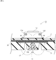
- FIG. 1 A cross-sectional view schematically showing the tire wear measuring device according to the embodiment of the present invention, (b) Cross-sectional view schematically showing the shape of the magnetic material in the tire wear measuring device.
- Explanatory drawing schematically showing the positional relationship between a magnetic material and a magnetic sensor in the tire wear measuring apparatus of FIG. 1 (a).
- FIG. 1A is a cross-sectional view schematically showing the tire wear measuring device 10 according to the present embodiment
- FIG. 1B is a cross-sectional view schematically showing the shape of the magnetic body 13 in the tire wear measuring device 10.
- FIG. 2 is a cross-sectional view schematically showing a main part of the tire wear measuring device 10 of FIG. 1 (a).
- 1A and 2A are also cross-sectional views showing a main part of a tire (pneumatic tire) 20.
- the tire wear measuring device 10 includes a magnetic body 13 embedded in the tread portion 23 and a magnetic sensor 12 arranged at a position facing the magnetic body 13 in the tire 20. There is.
- the magnetic sensor 12 arranged on the inner side surface 21 of the tire 20 and the magnetic body 13 embedded in the tread portion 23 of the outer surface 22 are viewed in a plan view from the radial direction (Y-axis direction) of the tire 20. They are arranged so that they overlap.
- the magnetic body 13 is embedded in the tread portion 23 of the outer surface 22 which is the contact patch between the road surface and the tire 20, and is shown in the figure as the tire 20 is used and the magnetic body 13 wears together with the tread portion 23.
- the magnetic field M generated from the magnetic material 13 indicated by the one-point chain line changes.
- the magnetic sensor 12 provided on the inner surface 21 of the tire 20 detects the magnetic flux density of the magnetic field M formed by the magnetic body 13.
- detecting the magnetic flux density of the magnetic field M is also described as appropriately detecting the magnetic field M.
- the tire wear measuring device 10 can measure the wear state of the tread portion 23 by detecting the magnetic field M with the magnetic sensor 12.
- the wear state of the tread portion 23 in the tire 20 can be measured based on the table in which the change in the magnetic field M due to the wear of the magnetic body 13 is stored in advance and the measured value of the magnetic field M.
- the tread portion 23 refers to a protruding portion on the surface of the tire 20 in contact with the ground of the tire 20.
- the magnetic material 13 wears as the tread portion 23 wears. Further, the magnetic body 13 is formed in a shape in which the area of the bottom surface 13B appearing on the ground contact surface of the tread portion 23 of the tire 20 becomes smaller as the wear progresses. By making the area of the bottom surface 13B of the magnetic body 13 smaller with wear, it is possible to suppress an increase in the demagnetic field MR with wear of the magnetic body 13.
- the magnetic sensor 12 detects the magnetic field M affected by the demagnetic field MR. Therefore, by suppressing the influence of the demagnetic field MR from increasing with the progress of wear, the linearity between the amount of wear of the magnetic material 13 and the amount of change in the magnetic flux density of the magnetic field M is improved.
- good linearity means a relationship in which a graph becomes close to a straight line when graphed. The relationship between the shape of the magnetic body 13, the demagnetizing field MR, and the linearity will be described below with reference to FIGS. 3 (a) and 3 (b).
- FIG. 3A is a perspective view of the magnetic body 13 in the tire wear measuring device 10 of the present embodiment as viewed from the bottom surface 13B side, and schematically changes the shape, the magnetic field M, and the demagnetic field MR due to the wear of the magnetic body 13. Is shown.
- the magnetic material 13 in the initial state before wear is shown on the left side
- the magnetic material 13 in the wear state at the time when wear progresses is shown on the right side.
- FIG. 3B is a perspective view schematically showing changes in the shape, the magnetic field M, and the demagnetic field MR due to the wear of the magnetic body 53 in the conventional tire wear measuring device.
- the magnetic material 53 in the initial state at the time before wear is shown on the left side
- the magnetic material 53 in the wear state at the time when wear progresses is shown on the right side.
- the shape of the magnetic body 53 of the conventional tire wear measuring device is a cylindrical shape having the same cross-sectional shape cut in the extension direction. Therefore, the diameter LBn of the bottom surface 53B appearing on the ground contact surface of the tread portion 23 on the outer surface 22 of the tire 20 does not change due to the wear of the magnetic body 53. As described above, the diameter LBn and the area of the bottom surface 53B do not change even if the wear progresses, and are the same in the initial state and the wear state. Further, the diameter LAN and the area of the upper surface 53A do not change with the progress of wear.
- the demagnetizing field MRn in the worn state becomes larger than the demagnetic field MRs in the initial state (MRs ⁇ MRn).
- the magnetic field Mn outside the magnetic body 53 in the worn state becomes Hn in the worn state whose height is smaller than Hs in the initial state as the magnetic body 53 is worn (Hs> Hn).
- the magnetic sensor detects the magnetic field Mn affected by the demagnetic field MRn. Therefore, the amount of change in the magnetic field M detected by the magnetic sensor is larger than the amount of wear of the magnetic body 53.
- the demagnetizing field refers to a magnetic field inside a magnetic material different from the magnetic field emitted outside the magnetic material in the flow of the magnetic field (magnetic flux) from the N pole to the S pole. Since this demagnetizing field is opposite to the direction of the magnetic field returning from the outside at one end of the magnetic material, it acts as a coercive force that weakens the magnetic flux density of the magnetic field of the magnetic material. In the case of a rod-shaped magnetic material (magnet), the smaller the dimensional ratio (height / cross-sectional area), the greater the effect of the demagnetizing field on weakening the magnetic field of the magnetic material.
- the demagnetizing field MR inside the magnetic body 53 weakens the magnetic field M outside.
- the magnetic field M outside the magnetic body 53 becomes smaller as the wear progresses, while the demagnetic field MR becomes larger. Therefore, in the worn state, the relative magnitude (ratio) of the demagnetizing field MR with respect to the external magnetic field M is larger than in the initial state. Therefore, the magnetic field M of the magnetic body 53 is strongly affected by the demagnetic field MR as the wear progresses. It has been found that this is one of the factors that reduce the linearity between the amount of wear of the magnetic material 53 and the magnetic flux density of the magnetic field M.
- the height H changes while the cross-sectional shapes of the upper surface 53A and the bottom surface 53B are constant as the wear progresses. Therefore, as the wear of the magnetic body 53 progresses, the change in the dimensional ratio (height Hn / diameter LBn) becomes large, and the influence of the internal demagnetic field MRn on the magnetic field Mn outside the magnetic body 53 becomes strong. Therefore, the amount of change in the magnetic flux density of the magnetic field Mn becomes smaller than the amount of change in the height Hn due to the wear of the magnetic body 53, and the linearity of both is lowered.
- the shape of the magnetic body 13 is a truncated cone.
- the area of the bottom surface 13B of the magnetic body 13 that appears on the surface of the tread portion 23 becomes smaller as the magnetic body 13 wears due to the wear of the tread portion 23, so that the dimensional ratio (height H / cross-sectional area) Can be prevented from becoming smaller as the magnetic body 13 wears.
- the cross-sectional area of the magnetic body 13 means the average of the areas of the upper surface 13A and the bottom surface 13B of the magnetic body 13.
- the shape of the magnetic material 13 is a cone.
- the top portion may be damaged when the magnetic material 13 is embedded in the tread portion 23. Therefore, in the tire wear measuring device 10, in order to improve the linearity while preventing damage, the shape of the magnetic body 13 is a truncated cone with an upper surface 13A.
- the ratio to LAs is preferably 1.0 or more and 2.5 or less, more preferably 1.2 or more and 2.3 or less, and further preferably 1.5 or more and 2.0 or less.
- the area ratio (bottom surface 13B / top surface 13A) between the bottom surface 13B and the top surface 13A of the magnetic material 13 is preferably 1.0 or more and 6.3 or less, more preferably 1.4 or more and 5.3 or less, and 2.3 or more and 4 The following is more preferable.
- the height Hs of the magnetic body 13 at the time before using the tire 20 depends on the shape of the tread portion 23, but is, for example, about 15 mm to 20 mm.
- the shape of the magnetic body 13 is preferably a truncated cone because the variation in the detected magnetic field due to the influence of the positional deviation from the magnetic sensor 12 arranged inside the tire 20 can be reduced and it is easy to embed it in the tread portion 23.
- the shape of the magnetic body 13 is not limited to the truncated cone, and any shape may be used as long as the area that appears on the ground plane of the tread portion 23 becomes smaller due to wear. Examples of such a shape include a triangular frustum, a frustum such as a quadrangular frustum, and the like.
- the bottom surface 13B which is one end in the radial direction (Y-axis direction) of the tire 20, is exposed to the ground contact surface of the tread portion 23, and the other end surface of the magnetic body 13 is the other end.
- 13A is embedded in the tread portion 23 so as to be located on the inner side surface 21 side of the safety wear limit (for example, in a passenger car tire, a position where the groove depth is 1.6 mm).
- the magnetic material 13 may be embedded in a state other than this.
- the bottom surface 13B may not be exposed to the ground plane of the tread portion 23 and may be located inside the tread portion 23.
- the ground contact surface of the tread portion 23 is worn to the position of the bottom surface 13B, so that the bottom surface 13B is exposed to the ground contact surface of the tread portion 23 on the outer surface 22 of the tire 20, and thereafter, both the tread portion 23 and the magnetic material 13 are exposed. Wears and the magnetic field M changes.
- the upper surface 13A may be embedded so as to substantially coincide with the position of the wear limit for safety or to be located on the outer surface 22 side of the position of the wear limit. In this case, the magnetic field M of the magnetic material 13 becomes 0 when the tread portion 23 reaches the safety wear limit or before that.
- the method of embedding the magnetic material 13 in the tread portion 23 is not particularly limited, but for example, after the tire 20 is manufactured, the magnetic material 13 can be embedded by driving the magnetic material 13 into the tread portion 23. Compared to the case where the magnetic body 13 is embedded in the tread portion 23 when the tire 20 is molded, it is not necessary to hold the magnetic body 13 in the molding die, so that the tire 20 is manufactured by almost the same method as the conventional proven manufacturing method. There are merits such as being able to manufacture with.
- the magnetic material 13 can be driven by using the same technique as driving the non-slip studs of the studded tire. When the magnetic body 13 is embedded in the tread portion 23, the magnetic body 13 is embedded in the tire 20 so that the magnetizing direction thereof and the radial direction of the tire 20 coincide with each other.
- the magnetic sensor 12 detects the magnetic field of the magnetic body 13 embedded in the tire 20 and measures the wear of the tire 20.
- the magnetic sensor 12 has a magnetic sensor (first sensor) 12A and a magnetic sensor (second sensor) 12B.
- the magnetic sensors 12A and 12B measure the magnetic field M emitted from the magnetic body 13, and a magnetoresistive effect element whose resistance changes depending on the direction and strength of the magnetic field M is used.
- the magnetoresistive element include a GMR element and a TMR element.
- the measurement by the magnetic sensors 12A and 12B does not have to be performed continuously in real time, and may be performed intermittently at regular time intervals. Alternatively, the measurement may be performed in response to an external instruction received via a wireless communication means (not shown). By performing the measurement at regular time intervals or in response to instructions, power consumption can be suppressed as compared with continuous measurement.
- Hall elements may be used instead of the magnetoresistive effect elements of the magnetic sensors 12A and 12B, and changes in the strength of the magnetic flux may be measured. Further, the magnetic impedance effect element may be used as the magnetic sensors 12A and 12B to measure the change in impedance due to the change in the magnetic field.
- the magnetic sensors 12A and 12B of the present embodiment are configured to be capable of detecting, for example, the magnetic flux density in the X-axis direction.
- the magnetic sensors 12A and 12B may be configured to be able to detect not only the magnetic field in the X-axis direction but also the magnetic fields in the three-axis directions (X-axis, Y-axis and Z-axis) orthogonal to each other. It may be configured by using three sensors for uniaxial detection.
- the magnetic sensors 12A and 12B use a GMR sensor in which a GMR element is built in a mold package.
- the tire wear measuring device 10 outputs information on the wear of the tire 20 based on the measurement of the magnetic field by the magnetic sensors 12A and 12B to the vehicle side device, the portable terminal device, the external server, etc. via a wireless communication means or the like. good.
- Information on the measurement results of the magnetic sensors 12A and 12B can be transmitted to the vehicle-side device, and information from an external vehicle-side device or the like can be received via the wireless communication means.
- Information transmission / reception by communication between the tire wear measuring device 10 and an external device is controlled by an arithmetic unit (CPU) (not shown).
- CPU arithmetic unit
- FIG. 4 is an explanatory diagram schematically showing the positional relationship between the magnetic body 13 and the magnetic sensor 12A and the magnetic sensor 12B in the tire wear measuring device 10 of FIG. 1.
- the figure schematically shows the positional relationship of the tire 20 when viewed in a plan view from the radial direction (Y-axis direction). That is, in the figure, the back side of the drawing is the bottom surface 13B side, and the front side of the drawing is the top surface 13A side.
- the magnetic sensor 12 of the tire wear measuring device 10 has a magnetic sensor 12A and a magnetic sensor 12B, and the magnetic sensor 12A is arranged on one side of the magnetic body 13 when viewed in a plan view from the radial direction of the tire 20.
- the magnetic sensor 12B is arranged on the other side. Then, the magnetic sensor 12 detects the wear of the tread portion 23 based on the output of the magnetic sensor 12A and the output of the magnetic sensor 12B.
- the magnetic body 13 when viewed in a plan view from the radial direction of the tire 20, the magnetic body 13 is located on the straight line L connecting the magnetic sensor 12A and the magnetic sensor 12B, and is located from the center O of the magnetic body 13.
- the distance DA to the magnetic sensor 12A and the distance DB from the center O of the magnetic body 13 to the magnetic sensor 12B are equal.
- the magnetic sensor 12A and the magnetic sensor 12B are arranged symmetrically with respect to the center O of the magnetic body 13.
- the center O of the magnetic body 13 refers to the position of the central axis of the truncated cone.
- the magnetic field Ma detected by the magnetic sensor 12A and the magnetic field Mb detected by the magnetic sensor 12B have the same magnetic flux density and the directions of the magnetic fields are opposite to each other. Therefore, even if a problem occurs in one of the magnetic sensor 12A and the magnetic sensor 12B, the tire wear measuring device 10 can detect the amount of wear of the tire 20 based on the output of the other. Therefore, the redundancy of the tire wear measuring device 10 is improved.
- the external magnetic field that becomes noise when measuring the magnetic field M of the magnetic body 13 has the same effect on the magnetic sensor 12A and the magnetic sensor 12B. Therefore, the difference in output from these two sensors can be used to remove or suppress the effects of external magnetic fields. Also, since the outputs from the two sensors have opposite magnetic field directions, an output twice as large as the output from one sensor can be obtained while removing the influence of noise by using the difference between the two outputs. .. Therefore, it is possible to accurately measure the wear of the tire 20 by removing the influence of noise such as an external magnetic field and increasing the output.
- the magnetic sensor 12A and the magnetic sensor 12B in the tire wear measuring device 10 are arranged at positions that do not overlap with the magnetic body 13, respectively.
- the number of sensors included in the magnetic sensor 12 is not limited to two, and may be one or three or more.
- Examples of mounting the magnetic sensor 12 at a position facing the magnetic body 13 of the tire 20 include mounting on a socket provided on the inner side surface 21, direct adhesion to the inner side surface 21, and attaching to the inner side surface 21 of the tire 20. Embedding and the like can be mentioned. Since it is easy to install and replace, it is preferable to install it in a socket.
- the socket holds the magnetic sensor 12 in a replaceable state, and is fixed to the inner side surface 21 of the tire 20 by adhesive or the like, and includes a holding portion capable of holding the magnetic sensor 12.
- the socket is made of a shrinkable material such as a rubber material and can follow the deformation of the tire during traveling, and the holding portion uses the shrinkage to hold the magnetic sensor 12.
- the magnetic sensor 12 In order to accurately measure the wear of the tire 20, the magnetic sensor 12 is placed at a predetermined position in the tire 20 with respect to the magnetic body 13 embedded in the tread portion 23 (for example, when two sensors are provided). It is necessary to attach it to a position that has a positional relationship as shown in FIG. However, since the magnetic body 13 is arranged on the outer surface 22 of the tire 20, the magnetic sensor 12 is arranged on the inner surface 21 of the tire 20, so that the magnetic sensor 12 cannot be arranged at a predetermined position. Have difficulty. Therefore, as a method of attaching the magnetic sensor 12 to a predetermined position in the tire 20, for example, a magnetic field distribution observing device (magnet viewer) capable of observing the magnetic field distribution is used to attach the magnetic sensor 12 to the inner surface 21 of the tire 20. There is a method of mounting.
- a magnetic field distribution observing device magnet viewer
- the magnetic field distribution observation device By using the magnetic field distribution observation device, the magnetic field distribution generated by the magnetic body 13 arranged on the outer surface 22 of the tire 20 can be observed from the inner surface 21 side. Therefore, the place where the magnetic body 13 is embedded can be specified from the inside of the tire 20, and the magnetic sensor 12 can be attached to the inner surface of the tire 20.
- the magnetic field distribution observation device it becomes easy to attach the magnetic sensor 12 so that the relative positions with the magnetic body 13 have a predetermined relationship when viewed in a plan view from the Y-axis direction. Further, since the magnetic sensor 12 can be arranged at an appropriate position with respect to the arrangement position of the magnetic body 13, the tire wear measuring device 10 has good measurement accuracy. The same effect can be obtained by arranging the above-mentioned socket at a predetermined position by the above-mentioned method and attaching the magnetic sensor 12 to the socket.
- the magnetic material 13 is formed by dispersing particles (magnetic powder) of a hard magnetic material in a polymer material and magnetizing them in one direction, and the magnetizing direction coincides with the tire radial direction. It is buried in the tread part in such a posture. Since the magnetic body 13 becomes a permanent magnet by magnetism, a magnetic field having a predetermined magnetic flux density is formed around the magnetic body 13, and the magnet does not easily demagnetize after magnetization.
- preferred powders and granules include alcico magnets containing aluminum, nickel, cobalt and iron as main components, and ferrite magnets containing iron oxide as main components. Examples thereof include samarium, a samarium-based magnet containing iron as a main component, and magnetic powder for producing a neodymium-based magnet containing neodym, iron, and boron as main components.
- the polymer material a rubber material having the same composition as the tread rubber composition used for the tread portion 23 is preferable.
- the magnetic material 13 is preferably configured to have a magnetic flux density of 1 mT or more on the surface of the magnetic material. Further, from the viewpoint that the magnetic flux density of the magnetic body 13 can be reliably measured without being affected by the geomagnetism, it is configured to have a magnetic flux density of 0.05 mT or more at the measurement position where the magnetic sensors 12A and 12B are arranged. It is preferable that the magnetic flux density is 0.5 mT or more, and it is more preferable that the magnetic flux density is 0.5 mT or more.
- the tread portion 23 is embedded so that the difference from the magnetic field M detected by the magnetic sensors 12A and 12B is 1 mT or more.
- the magnetic material 13 may be provided only on one tread portion 23, or may be provided on a plurality of tread portions 23. Further, only one magnetic body 13 may be provided in the circumferential direction of the tire 20 in the tread portion 23, or a plurality of magnetic bodies 13 may be provided at equal intervals, for example.
- Magnetization of the magnetic body 13 can be performed using a known magnetizing device, for example, a condenser type magnetizing power supply device, a magnetizing coil, a magnetizing yoke, or the like.
- the timing of magnetism may be performed before being embedded in the tread portion 23 or after being embedded in the tread portion 23.
- the surface magnetic flux density of the magnetic material 13 is preferably 600 mT or less from the viewpoint of preventing the magnetic force of the magnetic material 13 from adversely affecting other in-vehicle electronic devices and the like.
- the surface magnetic flux density of the magnetic material 13 is more preferably 60 mT or less from the viewpoint of preventing metal pieces such as nails falling on the road surface from being adsorbed when traveling on the road.
- the surface magnetic flux density of the magnetic material is a value measured by bringing the tesla meter into direct contact with the surface of the magnetized magnetic material 13.
- the tire wear measuring device 10 of the present embodiment measures the wear state of the tire 20 provided with the tire wear measuring device 10 of the present invention according to the following procedure. 1. 1. Preliminary data acquisition Prior to measurement, the magnetic flux density of the magnetic field, which changes due to wear of the magnetic material, is measured in advance for the same type of tire as the measurement target by a magnetic sensor provided on the surface of the cavity, and data is acquired. do.
- the magnetic flux density of a new tire (the same type of tire as the measurement target) immediately after manufacture is measured, and then the tire is used with a tire wear drum tester until the wear limit is exceeded. , Wearing the tires. Then, on the way, the device is stopped at predetermined time intervals, and the amount of wear and the magnetic flux density at that time are measured. Alternatively, some wear amount may be set, the device may be stopped each time the set wear amount is reached, and the magnetic flux density at the set wear amount may be measured.
- the tire wear measuring device may have a function of determining a wear state. In this case, the storage means of the tire wear measuring device stores the collation data, and outputs the determination result regarding the progress of wear to a device provided in the vehicle body or the like.
- FIG. 5A is a graph showing the linearity between the wear of the tread portion and the magnetic flux density for the magnetic materials of the examples having different shapes
- FIG. 5B is the diameter / top surface of the bottom surface. It is a graph which shows the diameter (B / A ratio) and linearity (linearity) of.
- the linearity error (%) in FIG. 5 (b) is the error (calculated value of the approximate straight line) between the approximate straight line obtained by using the least squares method and the measured value for the measurement results of each embodiment of FIG. 5 (a). It is the largest value among the ratio (%) of the absolute value of the error to.
- the amount of wear of the tread portion corresponds to the amount of wear of the tread portion as compared with the comparative example in which the shape of the magnetic material is cylindrical.
- the linearity of the graph between the height of the magnetic material and the sensor output corresponding to the magnetic flux density of the magnetic field M of the magnetic material has been improved.
- the linearity of the graph was improved by increasing the ratio of the diameter of the bottom surface (B / A ratio) to the diameter of the top surface of the magnetic material of the truncated cone.
- the present invention can be applied to a tire wear measuring device capable of measuring a tire wear state without visual inspection.
- Tire wear measuring device 12 Magnetic sensor 12A: Magnetic sensor (first sensor) 12B: Magnetic sensor (second sensor) 13: Magnetic material 13A: Top surface 13B: Bottom surface 20: Tire 21: Inner side surface 22: Outer surface (ground plane) 23: Tread portion 53: Magnetic material 53A: Top surface 53B: Bottom surface DA, DB: Distance H: Height Hs: Height (initial state) Hn: Height (wear state) LAs, LBs: Diameter (initial state) LAN, LBn: Diameter (wear state) M, Ma, Mb: Magnetic field Ms: Magnetic field (initial state) Mn: Magnetic field (wear state) MR: Demagnetizing field MRs: Demagnetic field (initial state) MRn: Demagnetizing field (wear state) O: Center L: Straight line
Landscapes
- Physics & Mathematics (AREA)
- General Physics & Mathematics (AREA)
- Engineering & Computer Science (AREA)
- Mechanical Engineering (AREA)
- Tires In General (AREA)
- Measurement Of Length, Angles, Or The Like Using Electric Or Magnetic Means (AREA)
Abstract
磁性体の摩耗と磁束密度との線形性が良く、トレッド部の摩耗を精度よく検出できる本発明のタイヤ摩耗測定装置10は、トレッド部23に埋設され前記トレッド部の摩耗に伴い摩耗する磁性体13と、タイヤ20内の磁性体13に対向する位置に配置された磁気センサ12と、を備え、磁気センサ12は、磁性体13により形成される磁界Mの磁束密度の変化を検知するタイヤ摩耗測定装置10において、磁性体13の底面13Bがトレッド部23の接地面である外側面22に現われ、底面13Bの面積がトレッド部23の摩耗に伴って小さくなる。
Description
本発明は、空気入りタイヤに埋設された磁性体の磁界に基づいてトレッド部の摩耗を検出するタイヤ摩耗測定装置、空気入りタイヤおよびタイヤ摩耗測定方法に関する。
空気入りタイヤ(以下、適宜タイヤともいう)のトレッド部の摩耗が進行すると、路面を走行する際におけるグリップ性能や、濡れた路面を走行する際におけるタイヤと路面との間の水を排出する排水性能が低下する。そこで、運転者や車両管理者は、タイヤのトレッドの摩耗状態を目視で点検し、安全性を確保するために使用限度を超える前にタイヤを交換する。目視による点検にはタイヤの溝に設けられているスリップサインなどが用いられる。しかし、点検作業は煩雑であり、また、摩耗状態の評価を誤るおそれもある。ユーザーによっては点検を行わないことも考えられる。評価を誤った場合、性能が低下したタイヤが継続して使用されることになり、安全性の観点から好ましくない。
そこで、目視以外の方法によってトレッド部の摩耗の程度を測定するための装置が提案されている。たとえば、特許文献1には、トレッド部のタイヤ半径方向の磁界の磁束密度を検知する磁気センサを有し、磁気センサにより検知された磁束密度によりトレッド部の摩耗を測定するように構成されたタイヤ摩耗測定システムが記載されている。
特許文献1に記載のシステムは、タイヤのトレッド部に埋設され、トレッド部とともに摩耗する磁性体が発する磁界の変化から、トレッド部の摩耗を検知する。トレッド部の摩耗を精度よく検知するためには、磁性体が発する磁界の磁束密度が磁性体の摩耗に伴って直線的に変化すること、すなわち磁性体の摩耗量と磁束密度の変化量との線形性が良いことが好ましい。
本発明は、磁性体の摩耗量と磁束密度の変化量との線形性が良く、トレッド部の摩耗を精度よく検出できるタイヤ摩耗測定装置、空気入りタイヤおよびタイヤ摩耗測定方法を提供することを目的としている。
本発明は、トレッド部に埋設され前記トレッド部の摩耗に伴い摩耗する磁性体と、タイヤの前記磁性体に対向する位置に配置された磁気センサと、を備え、前記磁気センサは、前記磁性体により形成される磁界の磁束密度の変化を検知するタイヤ摩耗測定装置において、前記磁性体の底面が前記トレッド部の接地面に現われ、前記底面の面積が前記トレッド部の摩耗に伴って小さくなることを特徴とするタイヤ摩耗測定装置を提供する。
上記の構成により、トレッド部の接地面に現われる底面の面積が一定である従来の磁性体と比較して、磁性体の摩耗量と磁束密度の変化量との間の線形性を向上させることができる。
上記の構成により、トレッド部の接地面に現われる底面の面積が一定である従来の磁性体と比較して、磁性体の摩耗量と磁束密度の変化量との間の線形性を向上させることができる。
前記磁性体の形状は、錐台が好ましく、円錐台がより好ましい。
磁性体を錘台とすることにより、トレッド部の接地面に現われる底面の面積がトレッド部の摩耗に伴って連続的かつ滑らかに変化する。したがって、磁性体の摩耗量と磁束密度の変化量との間の線形性が良好になる。磁性体における底面とは反対側の端が平面(上面)である錐台とすることで、トレッド部に埋設する際に磁性体の一部に破損が生じることを抑え、容易かつ安定的に磁性体を埋設できる。磁性体の形状を側面が滑らかな円錐台とすれば、タイヤ内部に配置する磁気センサとの位置ずれの影響による検出磁界のばらつきを低減できる。また、より円滑に磁性体をトレッド部に埋設することができる。
磁性体を錘台とすることにより、トレッド部の接地面に現われる底面の面積がトレッド部の摩耗に伴って連続的かつ滑らかに変化する。したがって、磁性体の摩耗量と磁束密度の変化量との間の線形性が良好になる。磁性体における底面とは反対側の端が平面(上面)である錐台とすることで、トレッド部に埋設する際に磁性体の一部に破損が生じることを抑え、容易かつ安定的に磁性体を埋設できる。磁性体の形状を側面が滑らかな円錐台とすれば、タイヤ内部に配置する磁気センサとの位置ずれの影響による検出磁界のばらつきを低減できる。また、より円滑に磁性体をトレッド部に埋設することができる。
前記磁気センサは、第1センサと第2センサとを有し、前記タイヤの半径方向から平面視したときに、前記磁性体を挟んで、一方側に前記第1センサが配置され、他方側に前記第2センサが配置され、前記第1センサの出力と前記第2センサの出力とに基づいて前記トレッド部の摩耗を検知してもよい。
タイヤの半径方向からの平面視において、磁性体の一方側と他方側とでは磁界の向きが逆向きである。このため、第1センサの出力と第2センサの出力との差を用いることにより、一つの磁気センサよりも大きな出力を得ることができる。また、外部磁界のようなノイズの影響は第1センサと第2のセンサに等しく及ぶことから、両出力の差を用いることによりノイズを抑制できる。
前記磁気センサは、第1センサと第2センサとを有している場合、前記タイヤの半径方向から平面視したときに、前記磁性体が、前記第1センサと前記第2センサとを結んだ直線上に位置し、前記磁性体の中心からの前記第1センサまでの距離と、前記磁性体の中心からの前記第2センサまでの距離とが等しいことが好ましい。
上記の構成により、第1センサと第2センサとが検知する反対向きの磁界の磁束密度の大きさが同程度になる。このため、いずれか一方の出力のみに基づいて磁性体の摩耗量を検知することができるから、磁気センサの冗長性が向上する。
本発明は、本発明のタイヤ摩耗測定装置を備えており、前記磁性体は、硬磁性材料の粉粒体が高分子材料中に分散されて形成されるとともに一方向に着磁されて成り、着磁方向とタイヤ半径方向とが一致するように前記トレッド部に埋設されていることを特徴とする空気入りタイヤを提供する。
本発明は、本発明のタイヤ摩耗測定装置により前記タイヤの摩耗状態を測定するタイヤ摩耗測定方法であって、前記磁性体の摩耗により変化する磁界の磁束密度を前記磁気センサにより測定し、測定された磁束密度の変化に基づいて前記タイヤの前記トレッド部の摩耗状態を測定することを特徴とするタイヤ摩耗測定方法を提供する。
本発明は、トレッド部の接地面に現われる底面の面積がトレッド部の摩耗に伴って小さくなる磁性体をトレッド部に埋設することによって、トレッド部の摩耗に伴い摩耗する磁性体の摩耗量と磁束密度の変化量との間の線形性が向上する。すなわち、トレッド部の摩耗量と磁束密度の変化量との間の線形性が向上すると言える。したがって、検知精度が良好なタイヤ摩耗測定装置、空気入りタイヤおよびタイヤ摩耗測定方法を提供することができる。
本発明の実施形態について、以下、図を参照しつつ説明する。各図において、同一の部材には同じ番号を付して、適宜、説明を省略する。
図1(a)は本実施形態に係るタイヤ摩耗測定装置10を模式的に示す断面図であり、図1(b)はタイヤ摩耗測定装置10における磁性体13の形状を模式的に示す断面図である。
図2は図1(a)のタイヤ摩耗測定装置10の要部を模式的に示す断面図である。
図1(a)および図2はタイヤ(空気入りタイヤ)20の要部を示す断面図でもある。
これらの図に示すように、タイヤ摩耗測定装置10は、トレッド部23に埋設された磁性体13と、タイヤ20内における磁性体13に対向する位置に配置された磁気センサ12と、を備えている。すなわち、タイヤ20の内側面21に配置された磁気センサ12と、外側面22のトレッド部23に埋設された磁性体13とが、タイヤ20の半径方向(Y軸方向)から平面視したときに重なるように配置されている。
図2は図1(a)のタイヤ摩耗測定装置10の要部を模式的に示す断面図である。
図1(a)および図2はタイヤ(空気入りタイヤ)20の要部を示す断面図でもある。
これらの図に示すように、タイヤ摩耗測定装置10は、トレッド部23に埋設された磁性体13と、タイヤ20内における磁性体13に対向する位置に配置された磁気センサ12と、を備えている。すなわち、タイヤ20の内側面21に配置された磁気センサ12と、外側面22のトレッド部23に埋設された磁性体13とが、タイヤ20の半径方向(Y軸方向)から平面視したときに重なるように配置されている。
磁性体13は、路面とタイヤ20との接地面となる外側面22のトレッド部23に埋設されており、タイヤ20が使用されトレッド部23とともに磁性体13が摩耗することに伴って、図中に一点鎖線で示す磁性体13から生じる磁界Mが変化する。タイヤ20の内側面21に設けられた磁気センサ12は、磁性体13により形成される磁界Mの磁束密度を検知する。以下では、磁界Mの磁束密度を検知することを、適宜、磁界Mを検知するとも記す。タイヤ摩耗測定装置10は、磁気センサ12で磁界Mを検知することにより、トレッド部23の摩耗状態を測定できる。例えば、磁性体13の摩耗に伴う磁界Mの変化をあらかじめ記憶したテーブルと磁界Mの測定値とに基づいて、タイヤ20におけるトレッド部23の摩耗状態を測定することができる。本実施形態において、トレッド部23とは、タイヤ20の地面に接するタイヤ20表面の凸出した部分をいう。
磁性体13は、トレッド部23が摩耗するのに伴って摩耗する。また、磁性体13は、摩耗が進むにつれてタイヤ20のトレッド部23の接地面に現われる底面13Bの面積が小さくなる形状に形成されている。磁性体13の底面13Bの面積が摩耗に伴って小さくなる形状とすることで、磁性体13の摩耗に伴って反磁界MRが大きくなることを抑えることができる。
磁気センサ12は、反磁界MRの影響を受けた磁界Mを検知する。このため、摩耗の進行に伴って反磁界MRの影響が大きくなることを抑えることにより、磁性体13の摩耗量と磁界Mの磁束密度の変化量との間の線形性が向上する。本発明において線形性が良いとは、グラフ化した場合にグラフが直線に近くなる関係をいう。磁性体13の形状と、反磁界MRと、線形性との関係について、図3(a)および図3(b)を参照して以下に説明する。
図3(a)は本実施形態のタイヤ摩耗測定装置10における磁性体13を底面13B側から見た斜視図であり、磁性体13の摩耗に伴う形状、磁界Mおよび反磁界MRの変化を模式的に示している。同図では摩耗前における初期状態の磁性体13を向かって左側に示し、摩耗が進行した時点における摩耗状態の磁性体13を向かって右側に示している。
図3(b)は従来のタイヤ摩耗測定装置における磁性体53の摩耗に伴う形状、磁界Mおよび反磁界MRの変化を模式的に示す斜視図である。同図では摩耗前の時点における初期状態の磁性体53を向かって左側に示し、摩耗が進行した時点における摩耗状態の磁性体53を向かって右側に示している。
図3(b)に示すように、従来のタイヤ摩耗測定装置の磁性体53の形状は、伸長方向に切断した断面形状が等しい円柱形である。このため、タイヤ20の外側面22におけるトレッド部23の接地面に現われる底面53Bの直径LBnは、磁性体53の摩耗によって変化しない。このように、底面53Bの直径LBnおよび面積は、摩耗が進行しても変化せず、初期状態と摩耗状態とで同じである。また、上面53Aの直径LAnおよび面積も摩耗の進行に伴って変化しない。
円柱状の磁性体53の場合、高さ/断面積の比が小さいほど反磁界MRが大きくなる。断面積は摩耗の進行に伴って変わらないため、摩耗状態では、高さHnが初期状態の高さHsよりも小さくなった分だけ、高さ/断面積の比が小さくなる。したがって、摩耗状態における反磁界MRnは、初期状態における反磁界MRsよりも大きくなる(MRs<MRn)。対して、摩耗状態における磁性体53の外側の磁界Mnは、磁性体53の摩耗に伴ってその高さが初期状態のHsよりも小さい摩耗状態のHnになることで(Hs>Hn)、初期状態における磁界Msよりも小さくなる(Ms>Mn)。このため、磁性体53の場合、その内部に生じる反磁界MRが磁界Mへ及ぼす影響は、摩耗に伴って大きくなる(MRs/Ms<MRn/Mn)。磁気センサは、反磁界MRnの影響を受けた磁界Mnを検知する。このため、磁気センサにより検知される磁界Mの変化量は、磁性体53の摩耗量よりも大きくなる。
反磁界とは、N極からS極への磁界(磁束)の流れのうち、磁性体の外部に出る磁界とは別の磁性体の内部における磁界をいう。この反磁界は、磁性体の一端において外部から戻ってくる磁界の向きとは逆向きとなるから、磁性体の磁界の磁束密度を弱める減磁力として作用する。棒状の磁性体(磁石)の場合、寸法比(高さ/断面積)が小さいほど、反磁界が磁性体の磁界を弱める影響が大きくなる。
上述のとおり、磁性体53の内部の反磁界MRは外側の磁界Mを弱める。従来の磁性体53は、摩耗の進行に伴って、磁性体53外部の磁界Mが小さくなるのに対し、反磁界MRが大きくなる。このため、摩耗状態では、初期状態よりも、外部の磁界Mに対する反磁界MRの相対的な大きさ(割合)が大きくなる。したがって、磁性体53の磁界Mは、摩耗の進行に伴って、反磁界MRの影響を強く受けることとなる。このことが、磁性体53の摩耗量と磁界Mの磁束密度との線形性を低下させる一因であることを見出した。
すなわち、従来のタイヤ摩耗測定装置の磁性体53は、摩耗が進むにつれて、上面53Aおよび底面53Bの断面形状が一定であるのに対して、高さHが変化する。このため、磁性体53の摩耗の進行に伴って、寸法比(高さHn/直径LBn)の変化が大きくなり、磁性体53外部の磁界Mnに対する内部の反磁界MRnの影響が強くなる。したがって、磁界Mnの磁束密度の変化量が磁性体53の摩耗に伴う高さHnの変化量よりも小さくなり、両者の線形性が低下する。
以上のように、摩耗量と磁束密度の変化量との線形性が良くないという従来のタイヤ摩耗測定装置の問題の一因は、トレッド部に埋設された磁性体53の形状にある。
そこで、本発明のタイヤ摩耗測定装置10では、磁性体13の形状を円錐台としている。これにより、トレッド部23の表面に現われる磁性体13の底面13Bの面積がトレッド部23の摩耗に伴い摩耗する磁性体13の摩耗に伴って小さくなるため、寸法比(高さH/断面積)が磁性体13の摩耗に伴って小さくなることを抑えられる。したがって、磁界Mnに対する反磁界MRnの影響が摩耗の進行とともに大きくなることを抑えて、磁性体13の摩耗量と磁界Mnの磁束密度の変化量との間の線形性を向上させることができる。なお、磁性体13の断面積とは、磁性体13の上面13Aと底面13Bとの面積の平均をいう。
そこで、本発明のタイヤ摩耗測定装置10では、磁性体13の形状を円錐台としている。これにより、トレッド部23の表面に現われる磁性体13の底面13Bの面積がトレッド部23の摩耗に伴い摩耗する磁性体13の摩耗に伴って小さくなるため、寸法比(高さH/断面積)が磁性体13の摩耗に伴って小さくなることを抑えられる。したがって、磁界Mnに対する反磁界MRnの影響が摩耗の進行とともに大きくなることを抑えて、磁性体13の摩耗量と磁界Mnの磁束密度の変化量との間の線形性を向上させることができる。なお、磁性体13の断面積とは、磁性体13の上面13Aと底面13Bとの面積の平均をいう。
線形性を良好にする観点から、磁性体13の形状を円錐とすることが好ましい。しかし、磁性体13を円錐とすると、トレッド部23に磁性体13を埋設する際に頂部に破損が生じるおそれがある。そこで、タイヤ摩耗測定装置10は、破損を防止しながら線形性を良好にするために、磁性体13の形状を上面13Aのある円錐台としている。
トレッド部23への安定な埋設と線形性とを両立させる観点から、タイヤ20を使用する前の時点(初期状態、新品の状態)における、磁性体13の底面13Bの直径LBsと上面13Aの直径LAsとの比(LBs/LAs)は、1.0以上2.5以下が好ましく、1.2以上2.3以下がより好ましく、1.5以上2.0以下がさらに好ましい。磁性体13の底面13Bと上面13Aとの面積比(底面13B/上面13A)は、1.0以上6.3以下が好ましく、1.4以上5.3以下がより好ましく、2.3以上4以下がさらに好ましい。なお、タイヤ20を使用する前の時点における磁性体13の高さHsは、トレッド部23の形状によるが、例えば15mm~20mm程度である。
タイヤ20内部に配置する磁気センサ12との位置ずれの影響による検出磁界のばらつきを低減でき、トレッド部23への埋設が容易であるから、磁性体13の形状は円錐台が好ましい。ただし、磁性体13の形状は円錐台に限られず、摩耗に伴ってトレッド部23の接地面に現れる面積が小さくなる形状であれば良い。このような形状として、三角錐台、四角錐台などの錐台等が挙げられる。
磁性体13は、図1(a)および図2に示すように、タイヤ20の半径方向(Y軸方向)の一端である底面13Bがトレッド部23の接地面に露出し、他端である上面13Aが安全上の摩耗限度(例えば、乗用車タイヤでは、溝の深さ1.6mmとなる位置)よりも内側面21側に位置するようにトレッド部23に埋設される。
図1(a)および図2は、初期状態の一例であり、磁性体13はこれ以外の状態で埋設されてもよい。例えば、初期状態では、底面13Bがトレッド部23の接地面に露出せず、トレッド部23の内部に位置してもよい。この場合、トレッド部23の接地面が底面13Bの位置まで摩耗することによって、底面13Bがタイヤ20の外側面22におけるトレッド部23の接地面に露出し、それ以降、トレッド部23ともに磁性体13が摩耗し、磁界Mが変化する。また、上面13Aは、安全上の摩耗限度の位置と略一致、または摩耗限度の位置よりも外側面22側に位置するように埋設されてもよい。この場合、トレッド部23が安全上の摩耗限度に達したとき、または、それよりも前に磁性体13の磁界Mが0になる。
トレッド部23に磁性体13を埋設する方法は特に限定されないが、例えば、タイヤ20の製造後において、磁性体13をトレッド部23に打ち込むことにより埋設することができる。タイヤ20の成形時に磁性体13をトレッド部23に埋設する場合に比べて、成形金型内で磁性体13を保持する必要がなくなるため、タイヤ20を従来の実績ある製造方法とほぼ同一の方法で製造することができるなどのメリットがある。なお、磁性体13の打ち込みは、スパイクタイヤ(studded tire)の滑り止めの鋲を打ち込むのと同様の技術を用いて行うことができる。トレッド部23に磁性体13を埋設する際、磁性体13は、その着磁方向とタイヤ20の半径方向とが一致するように、タイヤ20に埋設する。
磁気センサ12は、タイヤ20に埋設された磁性体13の磁界を検知してタイヤ20の摩耗を測定する。磁気センサ12は、磁気センサ(第1センサ)12Aと磁気センサ(第2センサ)12Bとを有している。
磁気センサ12A・12Bは、磁性体13からの放出された磁界Mを測定するものであり、磁界Mの方向、強さによって抵抗が変化する磁気抵抗効果素子が用いられる。磁気抵抗効果素子としては、GMR素子、TMR素子等が挙げられる。磁気センサ12A・12Bによる測定は、リアルタイムで連続的に行われる必要はなく、一定の時間毎に断続的に行われてもよい。あるいは、図示しない無線通信手段を介して受信した外部からの指示に応じて測定してもよい。一定の時間毎、あるいは指示に応じて測定を行うことにより、連続的に測定するよりも電力消費を抑制できる。磁気センサ12A・12Bである磁気抵抗効果素子の代わりにホール素子を使用し、磁束の強さの変化を計測してもよい。また磁気インピーダンス効果素子を磁気センサ12A・12Bとして用いて、磁界の変化によるインピーダンスの変化を計測してもよい。
本実施形態の磁気センサ12A・12Bは、例えば、X軸方向の磁束密度を検知可能に構成されている。ただし、X軸方向のみでなく、それぞれ、互いに直交する3軸方向(X軸、Y軸およびZ軸)の磁界を検知可能に構成されていてもよい、この場合、磁気センサ12A・12Bは、1軸検出のセンサ3つを用いて構成されてもよい。なお、本実施形態においては、磁気センサ12A・12BはモールドパッケージにGMR素子が内蔵されたGMRセンサを用いている。
タイヤ摩耗測定装置10は、磁気センサ12A・12Bによる磁界の測定に基づいたタイヤ20の摩耗に関する情報を、無線通信手段などを介して車両側装置、携帯端末装置、外部サーバなどに出力してもよい。無線通信手段を介して、車両側装置に磁気センサ12A・12Bによる測定結果の情報を送信したり、外部の車両側装置等からの情報を受信したりすることができる。タイヤ摩耗測定装置10と外部の装置との通信による情報の送受は図示しない演算装置(CPU)によって制御される。
図4は、図1のタイヤ摩耗測定装置10における、磁性体13と、磁気センサ12Aおよび磁気センサ12Bとの位置関係を模式的に示す説明図である。同図はタイヤ20の半径方向(Y軸方向)から平面視した場合における位置関係を模式的に示している。すなわち同図では、図面奥側が底面13B側であり、図面手前側が上面13A側である。タイヤ摩耗測定装置10の磁気センサ12は、磁気センサ12Aと磁気センサ12Bとを有し、タイヤ20の半径方向から平面視したときに、磁性体13を挟んで、一方側に磁気センサ12Aが配置され、他方側に磁気センサ12Bが配置されている。そして、磁気センサ12は、磁気センサ12Aの出力と磁気センサ12Bの出力とに基づいてトレッド部23の摩耗を検知する。
図4に示すように、タイヤ20の半径方向から平面視したときに、磁性体13が、磁気センサ12Aと磁気センサ12Bとを結んだ直線L上に位置し、磁性体13の中心Oからの磁気センサ12Aのまでの距離DAと、磁性体13の中心Oからの磁気センサ12Bまでの距離DBとが等しい。このように、磁気センサ12Aと磁気センサ12Bとは、磁性体13の中心Oに対して対称に配置されている。磁性体13の中心Oとは、円錐台の中心軸の位置をいう。
図4に示す構成により、磁気センサ12Aにより検知される磁界Maと、磁気センサ12Bにより検知される磁界Mbとは、磁束密度が同じで磁界の向きが逆になる。このため、タイヤ摩耗測定装置10は、磁気センサ12Aまたは磁気センサ12Bの一方に問題が生じた場合でも他方の出力に基づいて、タイヤ20の摩耗量を検知することが可能である。したがって、タイヤ摩耗測定装置10の冗長性が向上する。
そして、磁性体13の磁界Mを測定する際にノイズとなる外部磁界は、磁気センサ12Aと磁気センサ12Bとに同様に影響を及ぼす。このため、これらの二つのセンサからの出力の差を用いて、外部磁界の影響を取り除くことまたは抑制することができる。また、二つのセンサからの出力は磁界の向きが逆であるため、両出力の差を用いることによりノイズの影響を取り除きながら、一つのセンサからの出力の二倍の大きさの出力が得られる。したがって、外部磁界のようなノイズの影響を取り除くとともに出力を大きくして、タイヤ20の摩耗を精度よく測定することが可能になる。
図4に示す態様では、タイヤ摩耗測定装置10における磁気センサ12Aおよび磁気センサ12Bがそれぞれ、磁性体13と重ならない位置に配置されている。しかし、これは一例であり、Y軸方向から平面視した場合に、磁気センサ12Aおよび磁気センサ12Bの一部または全部が、磁性体13と重なるように配置されてもよい。また、磁気センサ12が備えるセンサは二つに限らず、一つまたは三つ以上でもよい。
タイヤ20の磁性体13に対向する位置に磁気センサ12を取り付ける態様としては、例えば、内側面21に設けられたソケットへの装着、内側面21への直接接着、タイヤ20の内側面21への埋め込み等が挙げられる。取り付け、交換が容易であることから、ソケットへの装着が好ましい。なお、ソケットとは、交換可能な状態で磁気センサ12を保持するものであり、タイヤ20の内側面21に接着などにより固定され、磁気センサ12を保持可能な保持部を備えている。ソケットは、ゴム材などの収縮性のある材質からなり、走行時のタイヤの変形に追従できるとともに、保持部はその収縮性を利用して磁気センサ12を保持する。
なお、タイヤ20の摩耗を精度よく測定するためには、トレッド部23に埋設された磁性体13に対して、磁気センサ12をタイヤ20内の所定の位置(例えば、センサを二つ有する場合、図4に示すような位置関係となる位置)に取り付ける必要がある。しかしながら、磁性体13はタイヤ20の外側面22に配置されているのに対して、磁気センサ12はタイヤ20の内側面21に配置されるため、磁気センサ12を所定の位置に配置することは困難である。そこで、タイヤ20内の所定の位置に磁気センサ12を取り付ける方法としては、例えば、磁界分布を観測可能な磁界分布観測装置(マグネットビューア)を用いて、磁気センサ12をタイヤ20の内側面21に取り付ける方法が挙げられる。
磁界分布観測装置を用いることで、タイヤ20の外側面22に配置されている磁性体13が発生する磁界分布を内側面21側から観測することができる。よって、タイヤ20の内側から磁性体13が埋設されている場所を特定し、磁気センサ12をタイヤ20の内面に取り付けることができる。磁界分布観測装置を用いることにより、Y軸方向から平面視した場合に、磁性体13との相対的な位置が所定の関係となるように磁気センサ12を取り付けることが容易になる。また、磁性体13の配置位置に対して、適切な位置に磁気センサ12を配置できるから、測定精度の良好なタイヤ摩耗測定装置10となる。なお、上述の方法で前述したソケットを所定の位置に配置し、そのソケットに磁気センサ12を取り付けても同様の効果が得られる。
磁性体13は、硬磁性材料の粉粒体(磁性粉)が、高分子材料中に分散されて形成され、一方向に着磁されて構成され、その着磁方向がタイヤ半径方向と一致するような姿勢でトレッド部に埋設される。磁性体13は着磁によって、永久磁石となるため、その周囲に所定の磁束密度の磁界を形成し、着磁後は容易に消磁することがない。
着磁後の保磁力が大きく容易に減磁しないという観点から、好ましい粉粒体として、アルミニウム、ニッケル、コバルト、鉄を主成分とするアルニコ系磁石、酸化鉄を主成分とするフェライト系磁石、サマリウム、鉄を主成分とするサマリウム系磁石、ネオジム、鉄、ホウ素を主成分とするネオジム系磁石作製用の磁性粉などが挙げられる。また、高分子材料としては、トレッド部23に用いられるトレッドゴム組成物と同じ配合のゴム材料などが好ましい。
磁性体13は、磁性体表面において1mT以上の磁束密度を有するように構成されていることが好ましい。また、地磁気に影響されず確実に磁性体13の磁束密度の測定ができるという観点から磁気センサ12A・12Bが配置されている測定位置において、0.05mT以上の磁束密度を有するように構成されていることが好ましく、0.5mT以上の磁束密度を有するように構成されていることがより好ましい。
磁性体13は、トレッド部23が摩耗する前の新品状態(初期状態、未摩耗状態)で、磁気センサ12によって検知される磁界M(磁束密度)と、トレッド部23が摩耗限度まで摩耗したときの状態で、磁気センサ12A・12Bによって検知される磁界Mとの差が1mT以上となるようにトレッド部23内に埋設されていることが好ましい。
磁性体13は、一つのトレッド部23にのみ設けられてもよく、複数のトレッド部23に設けられてもよい。さらに、磁性体13は、トレッド部23における、タイヤ20の周方向に1つのみ設けられてもよく、例えば等間隔に、複数設けられてもよい。
磁性体13への着磁は、公知の着磁装置、例えば、コンデンサー式着磁電源装置、着磁コイル、着磁ヨークなどを用いて行うことができる。なお、着磁を行うタイミングとしては、トレッド部23に埋設される前に実施してもよく、トレッド部23に埋設した後に実施してもよい。
一方、磁性体13の磁力によって、他の車載される電子機器などに悪影響を与えないようにするという観点から、磁性体13の表面磁束密度は600mT以下であることが好ましい。道路走行時に路面に落ちている釘などの金属片を吸着しないようにするという観点から、磁性体13の表面磁束密度は60mT以下であるとより好ましい。なお、磁性体の表面磁束密度は、着磁された磁性体13の表面にテスラメーターを直接接触させることにより測定される値である。
次に、本実施形態に係るタイヤ摩耗測定方法について説明する。
本実施形態のタイヤ摩耗測定装置10は、本発明のタイヤ摩耗測定装置10を備えたタイヤ20に対して、以下の手順にしたがってその摩耗状態を測定する。
1.事前のデータ取得
測定に先立って、予め、測定対象と同じ種類のタイヤについて、磁性体の摩耗により変化する磁場の磁束密度を内腔部表面に設けられている磁気センサにより測定し、データを取得する。
本実施形態のタイヤ摩耗測定装置10は、本発明のタイヤ摩耗測定装置10を備えたタイヤ20に対して、以下の手順にしたがってその摩耗状態を測定する。
1.事前のデータ取得
測定に先立って、予め、測定対象と同じ種類のタイヤについて、磁性体の摩耗により変化する磁場の磁束密度を内腔部表面に設けられている磁気センサにより測定し、データを取得する。
具体的には、まず、製造直後の新品タイヤ(測定対象と同じ種類のタイヤ)における磁束密度を測定し、その後、このタイヤに対して、タイヤ摩耗ドラム試験機を用いて、摩耗限度を超えるまで、タイヤを摩耗させていく。そして、途中、所定時間毎に装置を停止させて、その時点での摩耗量と磁束密度とを測定する。もしくは、いくつかの摩耗量を設定し、設定した摩耗量に達する毎に装置を停止させて、設定した摩耗量の時の磁束密度を測定してもよい。
その後、測定された各時点での摩耗量と磁束密度とに基づいて摩耗量と磁束密度との関係を示す照合用のデータを作成し、作成されたデータを車両本体に設けられた摩耗状態の判定に用いる装置に記憶させる。
2.測定対象タイヤの実車への装着と走行
次に、測定対象のタイヤを実車に装着して走行する。走行することにより、トレッド部とともに磁性体が摩耗していくため、磁気センサにより検知される磁束密度が変化する。
そして、磁気センサにより測定されたこの磁束密度の変化を、磁気センサから受信した摩耗状態の判定に用いる装置において、予め記憶されている照合用のデータと照合することにより、測定対象のタイヤにおいて、どの程度まで摩耗が進行しているかを判定することができる。なお、タイヤ摩耗測定装置が摩耗状態を判定する機能を備えていてもよい。この場合、タイヤ摩耗測定装置の有する記憶手段が照合用のデータを記憶し、摩耗が進行に関する判定結果を車両本体に設けられた装置などに出力する。
次に、測定対象のタイヤを実車に装着して走行する。走行することにより、トレッド部とともに磁性体が摩耗していくため、磁気センサにより検知される磁束密度が変化する。
そして、磁気センサにより測定されたこの磁束密度の変化を、磁気センサから受信した摩耗状態の判定に用いる装置において、予め記憶されている照合用のデータと照合することにより、測定対象のタイヤにおいて、どの程度まで摩耗が進行しているかを判定することができる。なお、タイヤ摩耗測定装置が摩耗状態を判定する機能を備えていてもよい。この場合、タイヤ摩耗測定装置の有する記憶手段が照合用のデータを記憶し、摩耗が進行に関する判定結果を車両本体に設けられた装置などに出力する。
以上説明した実施形態は、本発明の理解を容易にするために記載されたものであって、本発明を限定するために記載されたものではない。したがって、上記実施形態に開示された各要素は、本発明の技術的範囲に属する全ての設計変更や均等物をも含む趣旨である。
以下、実施例に基づいて、本発明をより具体的に説明する。
1.シミュレーションの構成
トラックバス用タイヤ(重荷重空気入りタイヤ)のトレッド標準配合ゴム材料に、平均粒径約175μmのネオジム粉末を混練した後、加硫成形することにより得られる、異なる形状を備えた磁性体について、摩耗の進行に伴う磁束密度の変化をシミュレーションにより評価した。
磁性体中に占めるネオジム粉末の配合量は、65重量%とした。なお、着磁は、加硫成形後のタイミングで、高さ方向に2.5Tの磁場を掛けて飽和磁化させることにより行う設定とした。シミュレーションによる評価の対象とした磁性体の形状を表1に示す。
1.シミュレーションの構成
トラックバス用タイヤ(重荷重空気入りタイヤ)のトレッド標準配合ゴム材料に、平均粒径約175μmのネオジム粉末を混練した後、加硫成形することにより得られる、異なる形状を備えた磁性体について、摩耗の進行に伴う磁束密度の変化をシミュレーションにより評価した。
磁性体中に占めるネオジム粉末の配合量は、65重量%とした。なお、着磁は、加硫成形後のタイミングで、高さ方向に2.5Tの磁場を掛けて飽和磁化させることにより行う設定とした。シミュレーションによる評価の対象とした磁性体の形状を表1に示す。

2.摩耗状態における直線性(線形性)の検証
4種類の磁性体について、摩耗に伴って高さHが段階的(18mm→15mm→12mm→9mm→6mm→3mm)に変化した各状態における磁束密度のシミュレーションを実施した。
初期状態からの変化をみるため、磁性体の高さ毎の磁束密度のシミュレーション結果としての磁気センサの出力値を表2および図5(a)に示す。
4種類の磁性体について、摩耗に伴って高さHが段階的(18mm→15mm→12mm→9mm→6mm→3mm)に変化した各状態における磁束密度のシミュレーションを実施した。
初期状態からの変化をみるため、磁性体の高さ毎の磁束密度のシミュレーション結果としての磁気センサの出力値を表2および図5(a)に示す。
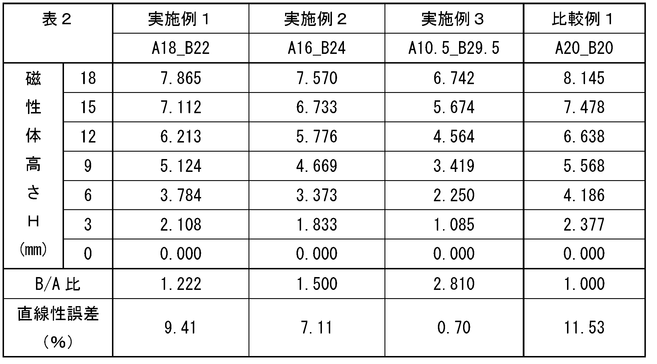
図5(a)は、形状の異なる実施例の磁性体について、トレッド部の摩耗と磁束密度との直線性(線形性)を示すグラフであり、図5(b)は、底面の直径/上面の直径(B/A比)と直線性(線形性)とを示すグラフである。図5(b)における直線性誤差(%)は、図5(a)の各実施例の測定結果について、最小二乗法を用いて求めた近似直線と実測値との誤差(近似直線の計算値に対する誤差の絶対値の割合(%))のうち、最も大きかった値である。
図5(a)および図5(b)に示すように、磁性体の形状を円錐台とした実施例はいずれも、磁性体の形状を円柱した比較例よりもトレッド部の摩耗量に対応する磁性体の高さと、磁性体の磁界Mの磁束密度に対応するセンサ出力とのグラフの直線性(線形性)が向上した。グラフの直線性は、円錐台の磁性体の上面の直径に対する底面の直径の比(B/A比)を大きくすることにより向上した。
本発明は、タイヤの摩耗状態を目視によらず測定可能なタイヤ摩耗測定装置に適用することができる。
10 :タイヤ摩耗測定装置
12 :磁気センサ
12A :磁気センサ(第1センサ)
12B :磁気センサ(第2センサ)
13 :磁性体
13A :上面
13B :底面
20 :タイヤ
21 :内側面
22 :外側面(接地面)
23 :トレッド部
53 :磁性体
53A :上面
53B :底面
DA、DB:距離
H :高さ
Hs :高さ(初期状態)
Hn :高さ(摩耗状態)
LAs、LBs:直径(初期状態)
LAn、LBn:直径(摩耗状態)
M、Ma、Mb:磁界
Ms :磁界(初期状態)
Mn :磁界(摩耗状態)
MR :反磁界
MRs :反磁界(初期状態)
MRn :反磁界(摩耗状態)
O :中心
L :直線
12 :磁気センサ
12A :磁気センサ(第1センサ)
12B :磁気センサ(第2センサ)
13 :磁性体
13A :上面
13B :底面
20 :タイヤ
21 :内側面
22 :外側面(接地面)
23 :トレッド部
53 :磁性体
53A :上面
53B :底面
DA、DB:距離
H :高さ
Hs :高さ(初期状態)
Hn :高さ(摩耗状態)
LAs、LBs:直径(初期状態)
LAn、LBn:直径(摩耗状態)
M、Ma、Mb:磁界
Ms :磁界(初期状態)
Mn :磁界(摩耗状態)
MR :反磁界
MRs :反磁界(初期状態)
MRn :反磁界(摩耗状態)
O :中心
L :直線
Claims (7)
- トレッド部に埋設され前記トレッド部の摩耗に伴い摩耗する磁性体と、タイヤ内の前記磁性体に対向する位置に配置された磁気センサと、を備え、
前記磁気センサは、前記磁性体により形成される磁界の磁束密度の変化を検知するタイヤ摩耗測定装置において、
前記磁性体の底面が前記トレッド部の接地面に現われ、
前記底面の面積が前記トレッド部の摩耗に伴って小さくなる
ことを特徴とするタイヤ摩耗測定装置。 - 前記磁性体の形状が錐台である、請求項1に記載のタイヤ摩耗測定装置。
- 前記磁性体の形状が円錐台である、請求項1に記載のタイヤ摩耗測定装置。
- 前記磁気センサは、第1センサと第2センサとを有し、
前記タイヤの半径方向から平面視したときに、前記磁性体を挟んで、一方側に前記第1センサが配置され、他方側に前記第2センサが配置され、
前記第1センサの出力と前記第2センサの出力とに基づいて前記トレッド部の摩耗を検知する、請求項1に記載のタイヤ摩耗測定装置。 - 前記タイヤの半径方向から平面視したときに、前記磁性体が、前記第1センサと前記第2センサとを結んだ直線上に位置し、
前記磁性体の中心からの前記第1センサまでの距離と、前記磁性体の中心からの前記第2センサまでの距離とが等しい、請求項4に記載のタイヤ摩耗測定装置。 - 請求項1ないし請求項5のいずれか1項に記載のタイヤ摩耗測定装置を備えており、
前記磁性体は、硬磁性材料の粉粒体が高分子材料中に分散されて形成されるとともに一方向に着磁されて成り、着磁方向とタイヤ半径方向とが一致するように前記トレッド部に埋設されていることを特徴とする空気入りタイヤ。 - 請求項1ないし請求項5のいずれか1項に記載のタイヤ摩耗測定装置により前記タイヤの摩耗状態を測定するタイヤ摩耗測定方法であって、
前記磁性体の摩耗により変化する磁界の磁束密度を前記磁気センサにより測定し、測定された磁束密度の変化に基づいて前記タイヤの前記トレッド部の摩耗状態を測定することを特徴とするタイヤ摩耗測定方法。
Priority Applications (1)
| Application Number | Priority Date | Filing Date | Title |
|---|---|---|---|
| JP2022557476A JP7387023B2 (ja) | 2020-10-22 | 2021-10-15 | タイヤ摩耗測定装置、空気入りタイヤおよびタイヤ摩耗測定方法 |
Applications Claiming Priority (2)
| Application Number | Priority Date | Filing Date | Title |
|---|---|---|---|
| JP2020177350 | 2020-10-22 | ||
| JP2020-177350 | 2020-10-22 |
Publications (1)
| Publication Number | Publication Date |
|---|---|
| WO2022085583A1 true WO2022085583A1 (ja) | 2022-04-28 |
Family
ID=81290528
Family Applications (1)
| Application Number | Title | Priority Date | Filing Date |
|---|---|---|---|
| PCT/JP2021/038211 Ceased WO2022085583A1 (ja) | 2020-10-22 | 2021-10-15 | タイヤ摩耗測定装置、空気入りタイヤおよびタイヤ摩耗測定方法 |
Country Status (2)
| Country | Link |
|---|---|
| JP (1) | JP7387023B2 (ja) |
| WO (1) | WO2022085583A1 (ja) |
Citations (12)
| Publication number | Priority date | Publication date | Assignee | Title |
|---|---|---|---|---|
| US5964265A (en) * | 1996-11-08 | 1999-10-12 | Continental Aktiengesellschaft | Vehicle tire with a device for determining tire-road adhesion |
| JP2003214808A (ja) * | 2002-01-21 | 2003-07-30 | Bridgestone Corp | タイヤの磨耗測定方法 |
| US20070035386A1 (en) * | 2003-10-03 | 2007-02-15 | Daniele Pullini | Tire wear monitoring system |
| US20090078347A1 (en) * | 2007-09-25 | 2009-03-26 | Alfred Niklas | Tire tread detection and measurement of physical variables of a tire on a moving vehicle |
| US20100276044A1 (en) * | 2007-07-27 | 2010-11-04 | Andreas Heise | Method for determining the profile depth of a tire and/or a tire characteristic, and a tire |
| US20180170118A1 (en) * | 2016-12-15 | 2018-06-21 | Bridgestone Americas Tire Operations, Llc | Tire with magnetic tread detection |
| JP2019064433A (ja) * | 2017-09-29 | 2019-04-25 | Toyo Tire株式会社 | 空気入りタイヤ、空気入りタイヤの製造方法、及び空気入りタイヤの摩耗状態判定方法 |
| JP2019064432A (ja) * | 2017-09-29 | 2019-04-25 | Toyo Tire株式会社 | 空気入りタイヤ、空気入りタイヤの製造方法、及び空気入りタイヤの摩耗状態判定方法 |
| WO2019107296A1 (ja) * | 2017-11-28 | 2019-06-06 | 横浜ゴム株式会社 | 空気入りタイヤ、タイヤ摩耗情報取得システム、及び空気入りタイヤの摩耗情報取得方法 |
| JP2019203831A (ja) * | 2018-05-25 | 2019-11-28 | 住友ゴム工業株式会社 | 空気入りタイヤ、タイヤ摩耗測定方法およびタイヤ摩耗測定システムならびにセンサモジュール |
| JP2020059154A (ja) * | 2018-10-05 | 2020-04-16 | 住友ゴム工業株式会社 | 空気入りタイヤの製造方法 |
| WO2020145012A1 (ja) * | 2019-01-09 | 2020-07-16 | アルプスアルパイン株式会社 | タイヤの摩耗測定装置 |
-
2021
- 2021-10-15 JP JP2022557476A patent/JP7387023B2/ja active Active
- 2021-10-15 WO PCT/JP2021/038211 patent/WO2022085583A1/ja not_active Ceased
Patent Citations (13)
| Publication number | Priority date | Publication date | Assignee | Title |
|---|---|---|---|---|
| US5964265A (en) * | 1996-11-08 | 1999-10-12 | Continental Aktiengesellschaft | Vehicle tire with a device for determining tire-road adhesion |
| JP2003214808A (ja) * | 2002-01-21 | 2003-07-30 | Bridgestone Corp | タイヤの磨耗測定方法 |
| US20070035386A1 (en) * | 2003-10-03 | 2007-02-15 | Daniele Pullini | Tire wear monitoring system |
| US20100276044A1 (en) * | 2007-07-27 | 2010-11-04 | Andreas Heise | Method for determining the profile depth of a tire and/or a tire characteristic, and a tire |
| US8240198B2 (en) * | 2007-07-27 | 2012-08-14 | Continental Teves Ag & Co. Ohg | Method for determining the profile depth of a tire and/or a tire characteristic, and a tire |
| US20090078347A1 (en) * | 2007-09-25 | 2009-03-26 | Alfred Niklas | Tire tread detection and measurement of physical variables of a tire on a moving vehicle |
| US20180170118A1 (en) * | 2016-12-15 | 2018-06-21 | Bridgestone Americas Tire Operations, Llc | Tire with magnetic tread detection |
| JP2019064433A (ja) * | 2017-09-29 | 2019-04-25 | Toyo Tire株式会社 | 空気入りタイヤ、空気入りタイヤの製造方法、及び空気入りタイヤの摩耗状態判定方法 |
| JP2019064432A (ja) * | 2017-09-29 | 2019-04-25 | Toyo Tire株式会社 | 空気入りタイヤ、空気入りタイヤの製造方法、及び空気入りタイヤの摩耗状態判定方法 |
| WO2019107296A1 (ja) * | 2017-11-28 | 2019-06-06 | 横浜ゴム株式会社 | 空気入りタイヤ、タイヤ摩耗情報取得システム、及び空気入りタイヤの摩耗情報取得方法 |
| JP2019203831A (ja) * | 2018-05-25 | 2019-11-28 | 住友ゴム工業株式会社 | 空気入りタイヤ、タイヤ摩耗測定方法およびタイヤ摩耗測定システムならびにセンサモジュール |
| JP2020059154A (ja) * | 2018-10-05 | 2020-04-16 | 住友ゴム工業株式会社 | 空気入りタイヤの製造方法 |
| WO2020145012A1 (ja) * | 2019-01-09 | 2020-07-16 | アルプスアルパイン株式会社 | タイヤの摩耗測定装置 |
Also Published As
| Publication number | Publication date |
|---|---|
| JP7387023B2 (ja) | 2023-11-27 |
| JPWO2022085583A1 (ja) | 2022-04-28 |
Similar Documents
| Publication | Publication Date | Title |
|---|---|---|
| US10113855B2 (en) | System for determining the thickness of a layer of rubber for a tire | |
| US20190359010A1 (en) | Pneumatic tire, tire wear measuring method, tire wear measuring system and sensor module | |
| JP7150251B2 (ja) | 空気入りタイヤの製造方法 | |
| JP7353579B2 (ja) | 空気入りタイヤ | |
| CN114423626A (zh) | 充气轮胎 | |
| JPWO2019107296A1 (ja) | 空気入りタイヤ、タイヤ摩耗情報取得システム、及び空気入りタイヤの摩耗情報取得方法 | |
| CN104422386A (zh) | 旋转检测装置 | |
| CN114248586A (zh) | 轮胎以及磨损度检测系统 | |
| EP1067389A1 (en) | Elastomeric tire having magnetized sidewall and method of manufacturing same | |
| JP7068504B2 (ja) | タイヤの摩耗測定装置 | |
| CN106405443B (zh) | 磁场传感器 | |
| JP7353581B2 (ja) | 空気入りタイヤ | |
| JP7387023B2 (ja) | タイヤ摩耗測定装置、空気入りタイヤおよびタイヤ摩耗測定方法 | |
| JP7353580B2 (ja) | 空気入りタイヤ | |
| US12098972B2 (en) | Wear measurement device and wear measurement method for tire | |
| JP4243249B2 (ja) | タイヤ、タイヤの形成方法、タイヤ外部磁界低減装置およびタイヤを装着した車両 | |
| WO2023002666A1 (ja) | タイヤ摩耗センサ、タイヤの摩耗度測定システム、タイヤの摩耗度評価装置およびタイヤの摩耗度評価方法 | |
| WO2021201095A1 (ja) | タイヤの摩耗測定装置および摩耗測定装置用の埋設ピン | |
| JP2017139401A (ja) | 磁気マーカ及び磁気マーカの作製方法 | |
| ATE438081T1 (de) | Verfahren und vorrichtung zur bestimmung der jeweiligen position wenigstens eines messortes in einem permanentmagnetfeld | |
| JP2022182439A (ja) | タイヤトレッド部の摩耗量取得方法および摩耗量取得システム | |
| WO2022201937A1 (ja) | タイヤ摩耗検知用の磁石、磁石を用いたタイヤ摩耗センサおよびタイヤ |
Legal Events
| Date | Code | Title | Description |
|---|---|---|---|
| 121 | Ep: the epo has been informed by wipo that ep was designated in this application |
Ref document number: 21882724 Country of ref document: EP Kind code of ref document: A1 |
|
| ENP | Entry into the national phase |
Ref document number: 2022557476 Country of ref document: JP Kind code of ref document: A |
|
| NENP | Non-entry into the national phase |
Ref country code: DE |
|
| 122 | Ep: pct application non-entry in european phase |
Ref document number: 21882724 Country of ref document: EP Kind code of ref document: A1 |