WO2022085550A1 - 炭素質材料及びその製造方法、並びに、含フッ素有機化合物除去材、浄水用フィルター及び浄水器 - Google Patents
炭素質材料及びその製造方法、並びに、含フッ素有機化合物除去材、浄水用フィルター及び浄水器 Download PDFInfo
- Publication number
- WO2022085550A1 WO2022085550A1 PCT/JP2021/038008 JP2021038008W WO2022085550A1 WO 2022085550 A1 WO2022085550 A1 WO 2022085550A1 JP 2021038008 W JP2021038008 W JP 2021038008W WO 2022085550 A1 WO2022085550 A1 WO 2022085550A1
- Authority
- WO
- WIPO (PCT)
- Prior art keywords
- carbonaceous material
- gas
- water
- volume
- oxygen
- Prior art date
- Legal status (The legal status is an assumption and is not a legal conclusion. Google has not performed a legal analysis and makes no representation as to the accuracy of the status listed.)
- Ceased
Links
Images


Classifications
-
- B—PERFORMING OPERATIONS; TRANSPORTING
- B01—PHYSICAL OR CHEMICAL PROCESSES OR APPARATUS IN GENERAL
- B01J—CHEMICAL OR PHYSICAL PROCESSES, e.g. CATALYSIS OR COLLOID CHEMISTRY; THEIR RELEVANT APPARATUS
- B01J20/00—Solid sorbent compositions or filter aid compositions; Sorbents for chromatography; Processes for preparing, regenerating or reactivating thereof
- B01J20/02—Solid sorbent compositions or filter aid compositions; Sorbents for chromatography; Processes for preparing, regenerating or reactivating thereof comprising inorganic material
- B01J20/20—Solid sorbent compositions or filter aid compositions; Sorbents for chromatography; Processes for preparing, regenerating or reactivating thereof comprising inorganic material comprising free carbon; comprising carbon obtained by carbonising processes
-
- B—PERFORMING OPERATIONS; TRANSPORTING
- B01—PHYSICAL OR CHEMICAL PROCESSES OR APPARATUS IN GENERAL
- B01D—SEPARATION
- B01D39/00—Filtering material for liquid or gaseous fluids
- B01D39/02—Loose filtering material, e.g. loose fibres
- B01D39/04—Organic material, e.g. cellulose, cotton
-
- B—PERFORMING OPERATIONS; TRANSPORTING
- B01—PHYSICAL OR CHEMICAL PROCESSES OR APPARATUS IN GENERAL
- B01D—SEPARATION
- B01D39/00—Filtering material for liquid or gaseous fluids
- B01D39/14—Other self-supporting filtering material ; Other filtering material
- B01D39/16—Other self-supporting filtering material ; Other filtering material of organic material, e.g. synthetic fibres
- B01D39/1607—Other self-supporting filtering material ; Other filtering material of organic material, e.g. synthetic fibres the material being fibrous
- B01D39/1623—Other self-supporting filtering material ; Other filtering material of organic material, e.g. synthetic fibres the material being fibrous of synthetic origin
-
- B—PERFORMING OPERATIONS; TRANSPORTING
- B01—PHYSICAL OR CHEMICAL PROCESSES OR APPARATUS IN GENERAL
- B01D—SEPARATION
- B01D39/00—Filtering material for liquid or gaseous fluids
- B01D39/14—Other self-supporting filtering material ; Other filtering material
- B01D39/20—Other self-supporting filtering material ; Other filtering material of inorganic material, e.g. asbestos paper, metallic filtering material of non-woven wires
- B01D39/2055—Carbonaceous material
- B01D39/2058—Carbonaceous material the material being particulate
-
- B—PERFORMING OPERATIONS; TRANSPORTING
- B01—PHYSICAL OR CHEMICAL PROCESSES OR APPARATUS IN GENERAL
- B01D—SEPARATION
- B01D39/00—Filtering material for liquid or gaseous fluids
- B01D39/14—Other self-supporting filtering material ; Other filtering material
- B01D39/20—Other self-supporting filtering material ; Other filtering material of inorganic material, e.g. asbestos paper, metallic filtering material of non-woven wires
- B01D39/2055—Carbonaceous material
- B01D39/2065—Carbonaceous material the material being fibrous
-
- B—PERFORMING OPERATIONS; TRANSPORTING
- B01—PHYSICAL OR CHEMICAL PROCESSES OR APPARATUS IN GENERAL
- B01J—CHEMICAL OR PHYSICAL PROCESSES, e.g. CATALYSIS OR COLLOID CHEMISTRY; THEIR RELEVANT APPARATUS
- B01J20/00—Solid sorbent compositions or filter aid compositions; Sorbents for chromatography; Processes for preparing, regenerating or reactivating thereof
- B01J20/28—Solid sorbent compositions or filter aid compositions; Sorbents for chromatography; Processes for preparing, regenerating or reactivating thereof characterised by their form or physical properties
- B01J20/28002—Solid sorbent compositions or filter aid compositions; Sorbents for chromatography; Processes for preparing, regenerating or reactivating thereof characterised by their form or physical properties characterised by their physical properties
- B01J20/28011—Other properties, e.g. density, crush strength
-
- B—PERFORMING OPERATIONS; TRANSPORTING
- B01—PHYSICAL OR CHEMICAL PROCESSES OR APPARATUS IN GENERAL
- B01J—CHEMICAL OR PHYSICAL PROCESSES, e.g. CATALYSIS OR COLLOID CHEMISTRY; THEIR RELEVANT APPARATUS
- B01J20/00—Solid sorbent compositions or filter aid compositions; Sorbents for chromatography; Processes for preparing, regenerating or reactivating thereof
- B01J20/28—Solid sorbent compositions or filter aid compositions; Sorbents for chromatography; Processes for preparing, regenerating or reactivating thereof characterised by their form or physical properties
- B01J20/28054—Solid sorbent compositions or filter aid compositions; Sorbents for chromatography; Processes for preparing, regenerating or reactivating thereof characterised by their form or physical properties characterised by their surface properties or porosity
- B01J20/28057—Surface area, e.g. B.E.T specific surface area
- B01J20/28066—Surface area, e.g. B.E.T specific surface area being more than 1000 m2/g
-
- B—PERFORMING OPERATIONS; TRANSPORTING
- B01—PHYSICAL OR CHEMICAL PROCESSES OR APPARATUS IN GENERAL
- B01J—CHEMICAL OR PHYSICAL PROCESSES, e.g. CATALYSIS OR COLLOID CHEMISTRY; THEIR RELEVANT APPARATUS
- B01J20/00—Solid sorbent compositions or filter aid compositions; Sorbents for chromatography; Processes for preparing, regenerating or reactivating thereof
- B01J20/28—Solid sorbent compositions or filter aid compositions; Sorbents for chromatography; Processes for preparing, regenerating or reactivating thereof characterised by their form or physical properties
- B01J20/28054—Solid sorbent compositions or filter aid compositions; Sorbents for chromatography; Processes for preparing, regenerating or reactivating thereof characterised by their form or physical properties characterised by their surface properties or porosity
- B01J20/28069—Pore volume, e.g. total pore volume, mesopore volume, micropore volume
- B01J20/28071—Pore volume, e.g. total pore volume, mesopore volume, micropore volume being less than 0.5 ml/g
-
- B—PERFORMING OPERATIONS; TRANSPORTING
- B01—PHYSICAL OR CHEMICAL PROCESSES OR APPARATUS IN GENERAL
- B01J—CHEMICAL OR PHYSICAL PROCESSES, e.g. CATALYSIS OR COLLOID CHEMISTRY; THEIR RELEVANT APPARATUS
- B01J20/00—Solid sorbent compositions or filter aid compositions; Sorbents for chromatography; Processes for preparing, regenerating or reactivating thereof
- B01J20/28—Solid sorbent compositions or filter aid compositions; Sorbents for chromatography; Processes for preparing, regenerating or reactivating thereof characterised by their form or physical properties
- B01J20/28054—Solid sorbent compositions or filter aid compositions; Sorbents for chromatography; Processes for preparing, regenerating or reactivating thereof characterised by their form or physical properties characterised by their surface properties or porosity
- B01J20/28078—Pore diameter
- B01J20/2808—Pore diameter being less than 2 nm, i.e. micropores or nanopores
-
- B—PERFORMING OPERATIONS; TRANSPORTING
- B01—PHYSICAL OR CHEMICAL PROCESSES OR APPARATUS IN GENERAL
- B01J—CHEMICAL OR PHYSICAL PROCESSES, e.g. CATALYSIS OR COLLOID CHEMISTRY; THEIR RELEVANT APPARATUS
- B01J20/00—Solid sorbent compositions or filter aid compositions; Sorbents for chromatography; Processes for preparing, regenerating or reactivating thereof
- B01J20/30—Processes for preparing, regenerating, or reactivating
-
- B—PERFORMING OPERATIONS; TRANSPORTING
- B01—PHYSICAL OR CHEMICAL PROCESSES OR APPARATUS IN GENERAL
- B01J—CHEMICAL OR PHYSICAL PROCESSES, e.g. CATALYSIS OR COLLOID CHEMISTRY; THEIR RELEVANT APPARATUS
- B01J20/00—Solid sorbent compositions or filter aid compositions; Sorbents for chromatography; Processes for preparing, regenerating or reactivating thereof
- B01J20/30—Processes for preparing, regenerating, or reactivating
- B01J20/3078—Thermal treatment, e.g. calcining or pyrolizing
-
- C—CHEMISTRY; METALLURGY
- C01—INORGANIC CHEMISTRY
- C01B—NON-METALLIC ELEMENTS; COMPOUNDS THEREOF; METALLOIDS OR COMPOUNDS THEREOF NOT COVERED BY SUBCLASS C01C
- C01B32/00—Carbon; Compounds thereof
- C01B32/30—Active carbon
- C01B32/312—Preparation
- C01B32/318—Preparation characterised by the starting materials
-
- C—CHEMISTRY; METALLURGY
- C01—INORGANIC CHEMISTRY
- C01B—NON-METALLIC ELEMENTS; COMPOUNDS THEREOF; METALLOIDS OR COMPOUNDS THEREOF NOT COVERED BY SUBCLASS C01C
- C01B32/00—Carbon; Compounds thereof
- C01B32/30—Active carbon
- C01B32/312—Preparation
- C01B32/318—Preparation characterised by the starting materials
- C01B32/324—Preparation characterised by the starting materials from waste materials, e.g. tyres or spent sulfite pulp liquor
-
- C—CHEMISTRY; METALLURGY
- C01—INORGANIC CHEMISTRY
- C01B—NON-METALLIC ELEMENTS; COMPOUNDS THEREOF; METALLOIDS OR COMPOUNDS THEREOF NOT COVERED BY SUBCLASS C01C
- C01B32/00—Carbon; Compounds thereof
- C01B32/30—Active carbon
- C01B32/312—Preparation
- C01B32/336—Preparation characterised by gaseous activating agents
-
- C—CHEMISTRY; METALLURGY
- C02—TREATMENT OF WATER, WASTE WATER, SEWAGE, OR SLUDGE
- C02F—TREATMENT OF WATER, WASTE WATER, SEWAGE, OR SLUDGE
- C02F1/00—Treatment of water, waste water, or sewage
- C02F1/28—Treatment of water, waste water, or sewage by sorption
- C02F1/286—Treatment of water, waste water, or sewage by sorption using natural organic sorbents or derivatives thereof
-
- B—PERFORMING OPERATIONS; TRANSPORTING
- B01—PHYSICAL OR CHEMICAL PROCESSES OR APPARATUS IN GENERAL
- B01D—SEPARATION
- B01D2239/00—Aspects relating to filtering material for liquid or gaseous fluids
- B01D2239/04—Additives and treatments of the filtering material
- B01D2239/0407—Additives and treatments of the filtering material comprising particulate additives, e.g. adsorbents
-
- B—PERFORMING OPERATIONS; TRANSPORTING
- B01—PHYSICAL OR CHEMICAL PROCESSES OR APPARATUS IN GENERAL
- B01D—SEPARATION
- B01D2239/00—Aspects relating to filtering material for liquid or gaseous fluids
- B01D2239/04—Additives and treatments of the filtering material
- B01D2239/0442—Antimicrobial, antibacterial, antifungal additives
-
- B—PERFORMING OPERATIONS; TRANSPORTING
- B01—PHYSICAL OR CHEMICAL PROCESSES OR APPARATUS IN GENERAL
- B01D—SEPARATION
- B01D2239/00—Aspects relating to filtering material for liquid or gaseous fluids
- B01D2239/08—Special characteristics of binders
- B01D2239/086—Binders between particles or fibres
-
- B—PERFORMING OPERATIONS; TRANSPORTING
- B01—PHYSICAL OR CHEMICAL PROCESSES OR APPARATUS IN GENERAL
- B01D—SEPARATION
- B01D2257/00—Components to be removed
- B01D2257/20—Halogens or halogen compounds
- B01D2257/206—Organic halogen compounds
- B01D2257/2066—Fluorine
-
- B—PERFORMING OPERATIONS; TRANSPORTING
- B01—PHYSICAL OR CHEMICAL PROCESSES OR APPARATUS IN GENERAL
- B01J—CHEMICAL OR PHYSICAL PROCESSES, e.g. CATALYSIS OR COLLOID CHEMISTRY; THEIR RELEVANT APPARATUS
- B01J2220/00—Aspects relating to sorbent materials
- B01J2220/40—Aspects relating to the composition of sorbent or filter aid materials
- B01J2220/48—Sorbents characterised by the starting material used for their preparation
- B01J2220/4812—Sorbents characterised by the starting material used for their preparation the starting material being of organic character
- B01J2220/485—Plants or land vegetals, e.g. cereals, wheat, corn, rice, sphagnum, peat moss
-
- B—PERFORMING OPERATIONS; TRANSPORTING
- B01—PHYSICAL OR CHEMICAL PROCESSES OR APPARATUS IN GENERAL
- B01J—CHEMICAL OR PHYSICAL PROCESSES, e.g. CATALYSIS OR COLLOID CHEMISTRY; THEIR RELEVANT APPARATUS
- B01J2220/00—Aspects relating to sorbent materials
- B01J2220/40—Aspects relating to the composition of sorbent or filter aid materials
- B01J2220/48—Sorbents characterised by the starting material used for their preparation
- B01J2220/4875—Sorbents characterised by the starting material used for their preparation the starting material being a waste, residue or of undefined composition
- B01J2220/4881—Residues from shells, e.g. eggshells, mollusk shells
-
- C—CHEMISTRY; METALLURGY
- C01—INORGANIC CHEMISTRY
- C01P—INDEXING SCHEME RELATING TO STRUCTURAL AND PHYSICAL ASPECTS OF SOLID INORGANIC COMPOUNDS
- C01P2006/00—Physical properties of inorganic compounds
- C01P2006/12—Surface area
-
- C—CHEMISTRY; METALLURGY
- C01—INORGANIC CHEMISTRY
- C01P—INDEXING SCHEME RELATING TO STRUCTURAL AND PHYSICAL ASPECTS OF SOLID INORGANIC COMPOUNDS
- C01P2006/00—Physical properties of inorganic compounds
- C01P2006/14—Pore volume
-
- C—CHEMISTRY; METALLURGY
- C02—TREATMENT OF WATER, WASTE WATER, SEWAGE, OR SLUDGE
- C02F—TREATMENT OF WATER, WASTE WATER, SEWAGE, OR SLUDGE
- C02F2101/00—Nature of the contaminant
- C02F2101/30—Organic compounds
- C02F2101/32—Hydrocarbons, e.g. oil
- C02F2101/322—Volatile compounds, e.g. benzene
-
- C—CHEMISTRY; METALLURGY
- C02—TREATMENT OF WATER, WASTE WATER, SEWAGE, OR SLUDGE
- C02F—TREATMENT OF WATER, WASTE WATER, SEWAGE, OR SLUDGE
- C02F2101/00—Nature of the contaminant
- C02F2101/30—Organic compounds
- C02F2101/36—Organic compounds containing halogen
Definitions
- the present invention relates to a carbonaceous material. Further, the present invention relates to a method for producing the carbonaceous material, and a fluorine-containing organic compound removing material, a water purification filter and a water purifier using the carbonaceous material.
- Fluoro-containing organic compounds have unique properties that cannot be realized by other substances (heat resistance, excellent chemical resistance, can be used even under harsh conditions, no light absorption ability, etc.), so surfactants, emulsifiers, water repellents, etc. It has been used for various purposes such as fire extinguishing agents, waxes, carpet cleaning agents, and coating agents. Recently, applications as functional materials such as surface treatment agents for semiconductors and fuel cell constituent materials are increasing.
- the fluorine-containing surfactant is removed from the water to be treated by contacting the activated carbon containing 90% or more of the particles passing through the 75 ⁇ m filter with the water to be treated containing the fluorine-containing surfactant.
- Patent Document 1 A method has been reported (Patent Document 1).
- Patent Document 1 As in the technique proposed in Patent Document 1, there have been reports on the removal of fluorine-containing organic compounds from water using activated carbon.
- the technique described in Patent Document 1 is a technique mainly used for batch applications (treatment / purification of factory wastewater).
- the techniques reported so far are methods for removing PFAS from raw water (river water, etc.) in such batch applications and water purification plants, and the means for removing fluorine-containing organic compounds with a water purifier, etc.
- the current situation is that research has not progressed much yet.
- the water to be treated differs between the treatment at a water purification plant and the treatment with a water purifier (raw water and tap water), and the treatment time of the water to be treated is also significantly different. For example, it cannot be directly applied to a water purifier for home use.
- a main object of the present invention is to provide a carbonaceous material having high PFAS (PFOS, PFOA, etc.) removal performance that can be used in water purifier applications.
- PFAS PFOS, PFOA, etc.
- the carbonaceous material according to one aspect of the present invention has a benzene adsorption amount of 30 to 60%, a vitamin B12 adsorption amount of more than 50.0 mg / g, and is calculated from a nitrogen adsorption isotherm by the BJH method.
- the pore volume of the mesopores is 0.13 to 0.30 cm 3 / g.
- the method for producing a carbonaceous material according to another aspect of the present invention is to use a flow furnace and to use an oxygen-containing gas separately from the flow gas introduced from the hearth, in a gas obtained by summing the flow gas and the oxygen-containing gas. It is characterized in that it is introduced into a flow furnace so that the oxygen concentration is 0.004 to 1% by volume.
- the water purification filter according to still another aspect of the present invention contains the carbonaceous material and the fibrous binder as described above, the CSF value of the fibrous binder is 10 to 150 mL, and 100 parts by mass of the carbonic material. On the other hand, it is characterized by containing 4 to 10 parts by mass of a fibrous binder.
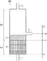
- FIG. 1 is a schematic diagram for explaining a method for producing a carbonaceous material using a flow furnace in one embodiment of the present invention.
- FIG. 2 is a schematic diagram for explaining a method for producing a carbonaceous material using a flow furnace in one embodiment of the present invention.
- FIG. 3 is a graph showing the relationship between the removal rates of PFOS and PFOA and Bed Volume in Examples and Comparative Examples of the present invention.
- the carbonaceous material according to the embodiment of the present invention has a benzene adsorption amount of 30 to 60%, a vitamin B12 adsorption amount of more than 50.0 mg / g, and is calculated from a nitrogen adsorption isotherm by the BJH method.
- the pore volume of the mesopores is 0.13 to 0.30 cm 3 / g.
- the amount of benzene adsorbed is an index showing the progress of activation of carbonaceous materials.
- the carbonaceous material according to the present embodiment is suitable for adsorbing PFAS because the amount of benzene adsorbed is in the range of 30 to 60%.
- the benzene adsorption amount of the carbonaceous material is in the range of 30 to 60%, and the upper limit is preferably 58% or less, more preferably 56% or less, still more preferably 55%.
- the lower limit is preferably 40% or more, more preferably 42% or more, still more preferably 44% or more.
- the amount of benzene adsorbed on the carbonaceous material can be measured by the method described in [Measurement of benzene adsorption amount] described later.
- Vitamin B12 (cyanocobalamin) has a large molecular weight of about 1355, and the amount of vitamin B12 adsorbed is an index of adsorption characteristics for a substance having a large molecular size.
- the carbonaceous material according to the present embodiment has a vitamin B12 adsorption amount of more than 50 mg / g, and thus is a carbonaceous material suitable for adsorbing PFAS.
- the adsorption amount of vitamin B12 of the carbonaceous material is more than 50 mg / g, preferably 60 mg / g or more, more preferably 70 mg / g or more, still more preferably 80 mg / g or more.
- the upper limit of the amount of vitamin B12 adsorbed is not particularly limited, but is usually preferably 500 mg / g or less, more preferably 460 mg / g or less, still more preferably, from the viewpoint of the balance with other physical property values such as the amount of benzene adsorbed. Is 420 mg / g or less.
- the amount of vitamin B12 adsorbed on the carbonaceous material can be measured by the method described in [Measurement of the amount of vitamin B12 adsorbed] described later.
- the pores of a carbonaceous material can be classified into micropores (less than 2 nm in diameter), mesopores (2-50 nm in diameter), and macropores (more than 50 nm in diameter) according to their diameter (IUPAC in parentheses). Indicates the classification criteria of).
- the mesopores are larger than the micropores, and the volume of the mesopores can be an index of the adsorption characteristics of a substance having a large molecular size.
- the carbonaceous material according to the present embodiment has a mesopore volume in the range of 0.130 to 0.30 cm 3 / g, which makes it a carbonaceous material more suitable for adsorption of PFAS.
- the mesopore volume of the carbonaceous material is in the range of 0.130 to 0.300 cm 3 / g, and the lower limit is preferably 0.140 cm 3 / g or more, more preferably. Is 0.145 cm 3 / g or more.
- the upper limit is preferably 0.280 cm 3 / g or less, and more preferably 0.250 cm 3 / g or less.
- the mesopore volume of the carbonaceous material can be calculated from the nitrogen adsorption isotherm using the BJH (Barrett-Joiner-Halenda) method.
- the measurement of the nitrogen adsorption isotherm and the calculation of the mesopore volume can be carried out by the methods described in [Measurement of nitrogen adsorption isotherm] and [Measurement of mesopore pore volume by BJH method] described later.
- the technical significance of each of the benzene adsorption amount, the vitamin B12 adsorption amount, and the mesopore pore volume in the present embodiment has been tried to explain, but the structure of the carbonaceous material (adsorption medium) and the adsorption characteristics for the adsorbent.
- the relationship is complicated, and the amount of benzene adsorbed, the amount of vitamin B12 adsorbed, and the volume of mesopores may not immediately correlate with the adsorption characteristics for the adsorbent independently.
- the carbonaceous material of the present embodiment is not particularly limited in other properties, but more. In order to surely obtain the effect of the present invention, it is considered preferable to have the characteristics described below.
- the carbonaceous material preferably has a specific surface area in the range of 1200 to 2000 m 2 / g from the viewpoint of achieving the adsorption removal performance required for a water purifier at a high level.
- the lower limit of the specific surface area is more preferably 1300 m 2 / g or more, or 1400 m 2 / g or more, and the upper limit is more preferably 1900 m 2 / g or less, or 1800 m 2 / g or less.
- the specific surface area of the carbonaceous material can be calculated from the nitrogen adsorption isotherm using the BET method.
- the measurement of the nitrogen adsorption isotherm and the calculation of the specific surface area can be carried out by the methods described in [Measurement of nitrogen adsorption isotherm] and [Measurement of specific surface area] described later.
- the carbonaceous material preferably has an average pore diameter in the range of 1.85 to 1.90 nm.
- the lower limit of the average pore diameter is more preferably 1.86 nm or more or 1.87 nm or more, and the upper limit is preferably 1.89 nm or less or 1.88 nm or less.
- the average pore diameter of carbonaceous material can be calculated from the nitrogen adsorption isotherm.
- the measurement of the nitrogen adsorption isotherm and the calculation of the average pore diameter can be carried out by the methods described in [Measurement of nitrogen adsorption isotherm] and [Measurement of total pore volume / average pore diameter] described later.
- the carbonaceous material according to the present embodiment preferably has a conductivity in the range of 3 to 9 S / cm as measured by powder resistance at a load of 12 kN.
- the upper limit of the conductivity is preferably 8.7 S / cm or less, more preferably 8.3 S / cm or less, still more preferably 8 S / cm or less, and the lower limit is preferably 5.3 S / cm or more, more preferably. It is 5.6 S / cm or more, more preferably 6 S / cm or more.
- the above-mentioned conductivity of a carbonaceous material can be measured by the method described in [Measurement of Conductivity] described later.
- the shape of the carbonaceous material is not particularly limited, and may be any shape such as a particle shape or a fibrous shape (thread shape, woven cloth (cloth) shape, felt shape), and can be appropriately selected according to a specific usage mode. However, since the adsorption performance per unit volume is high, the particulate form is preferable. In the case of a particulate carbonaceous material, its dimensions are not particularly limited, and the particle size and the like may be appropriately adjusted according to the specific usage mode.
- the raw material (carbonaceous precursor) of the carbonaceous material is not particularly limited.
- plant-based carbonaceous precursors eg, wood, shavings, coal, fruit husks such as coconut husks and walnut husks, fruit seeds, pulp production by-products, lignin, waste sugar honey and other plant-derived materials
- mineral-based Carbonaceous precursors eg, mineral-derived materials such as peat, subcarbon, brown charcoal, bituminous charcoal, smokeless coal, coke, coal tar, coal pitch, petroleum distillation residue, petroleum pitch
- synthetic resin-based carbonaceous precursors eg , Phenolic resin, polyvinylidene chloride, materials derived from synthetic resins such as acrylic resin
- natural fiber-based carbonaceous precursors for example, natural fibers such as cellulose, materials derived from natural fibers such as recycled fibers such as rayon), etc.
- a plant-based carbonaceous precursor is preferable because it is easy to use a carbonaceous material having excellent adsorption performance of the substance to be removed specified by the Household Goods Quality Labeling Law. Therefore, in one preferred embodiment, the carbonaceous material is derived from a plant-based carbonaceous precursor. From the viewpoint of realizing a carbonaceous material capable of removing PFAS more efficiently, it is preferable to use coconut shell as a raw material. Therefore, in one particularly preferred embodiment, palm husks are used as the plant-based carbonaceous precursor.
- the carbonaceous material according to this embodiment is suitable for adsorption of PFAS, and exhibits an excellent effect especially in water purifier applications. Therefore, the carbonaceous material of the present embodiment can be suitably used as a carbonaceous material for purifying water (carbonaceous material for water purification), and a carbonaceous material for purifying tap water (for purifying tap water). It can be more preferably used as a carbonaceous material).
- the carbonaceous material of the present embodiment has a Bed Volume of 12000 or more in removing performance of the fluorine-containing organic compound obtained under the following measurement conditions.
- the carbonaceous material of the present embodiment can efficiently adsorb the fluorine-containing organic compound, it can be suitably used as a fluorine-containing organic compound removing material. Therefore, the present invention also includes the fluorine-containing organic compound removing material made of the above-mentioned carbonaceous material.
- the carbonaceous material according to the embodiment of the present invention is produced by activating the carbonaceous precursor described above.
- carbonization is required prior to activation, it is usually sufficient to block oxygen or air and carbonize at, for example, 400 to 800 ° C (preferably 500 to 800 ° C, more preferably 550 to 750 ° C). ..
- the coking coal obtained by carbonizing the carbonaceous precursor is activated to produce a carbonaceous material.
- a carbonaceous material having a specific range of benzene adsorption amount, vitamin B12 adsorption amount, and mesopore pore volume (characteristics such as specific surface area, average pore diameter, conductivity, etc., which may be optionally filled if necessary).
- the activation method is important.
- the method for producing a carbonaceous material according to the present embodiment uses a flow furnace (fluid activation furnace) as an activation furnace, and uses a flow gas to be introduced from the hearth. Separately, it is characterized by introducing an oxygen-containing gas into a flow furnace.
- the amount of benzene adsorbed is 40 to 60% and vitamin B12 is adsorbed, which was difficult to achieve by the conventional method using a rotary kiln as an activation furnace or the conventional method of introducing a fluid gas exclusively from the hearth into a fluidized furnace. It is possible to realize a carbonaceous material having an amount of more than 50 mg / g.
- the fluid gas is not particularly limited as long as it has an action of fluidly activating the coking coal, and conventionally known ones may be used.
- the fluid gas includes a gas containing water vapor and / or carbon dioxide.
- a combustion gas of a hydrocarbon for example, a light gas such as methane, propane and butane, and a liquid fuel such as light oil, kerosene and heavy oil is preferably used.
- the water vapor concentration in the fluid gas is preferably 10 to 40% by volume.
- the upper limit is more preferably 35% by volume or less, or 30% by volume or less, and the lower limit is more preferably 12% by volume or more, 14% by volume or more, or 15% by volume or more.
- the carbon dioxide concentration in the fluid gas is preferably 15% by volume or less.
- the upper limit is more preferably 14% by volume or less or 13% by volume or less, and the lower limit is more preferably 8% by volume or more, 9% by volume or more, or 10% by volume or more.
- an oxygen-containing gas is introduced into the fluidized furnace separately from the fluidized gas introduced from the hearth.
- the oxygen-containing gas is introduced into the flow furnace so that the oxygen concentration in the total gas of the fluid gas and the oxygen-containing gas is 0.004 to 1% by volume.
- the oxygen concentration in the total gas of the fluid gas and the oxygen-containing gas is preferably 0.005% by volume or more, 0.01% by volume or more, and 0. It is 0.02% by volume or more, 0.03% by volume or more, 0.04% by volume or more, or 0.05% by volume or more.
- the upper limit of the oxygen concentration is preferably 0.95% by volume or less, 0.9% by volume or less, 0.85% by volume or less, or 0.8% by volume or less.
- the oxygen concentration in the gas which is the sum of the fluid gas and the oxygen-containing gas, is a charge-equivalent concentration calculated based on the composition and introduction amount of the fluid gas and the composition and introduction amount of the oxygen-containing gas.
- the oxygen-containing gas is not particularly limited as long as it contains oxygen, and for example, air and a gas obtained by diluting air with another gas (for example, an inert gas such as nitrogen) can be used.
- the oxygen concentration in the oxygen-containing gas is not particularly limited as long as the oxygen concentration in the gas including the fluidized gas and the oxygen-containing gas is in the range of 0.004 to 1% by volume, but is preferably 20% by volume or less. It is preferably 15% by volume or less, 10% by volume or less, 8% by volume or less, 6% by volume or less, 5% by volume or less, 4% by volume or less, 3% by volume or less, or 2% by volume or less.
- the lower limit of the oxygen concentration in the oxygen-containing gas is usually 0.1% by volume or more, 0.2% by volume or more, and the like.
- Oxygen may be contained in the flowing gas introduced from the hearth, but when a combustion gas is used as the flowing gas, it is generally difficult to control a trace amount of oxygen concentration in the combustion gas. It is preferable to control the oxygen concentration by oxygen derived from the oxygen-containing gas.
- FIG. 1 shows a schematic diagram of a flow furnace (flow activation furnace) 100 used in the manufacturing method of the present embodiment.
- each reference numeral is 1 fluid gas inlet, 2 oxygen-containing gas inlet, 3 gas outlet, 4 gas dispersion layer, 5 coking coal, 6 coking coal (at the time of fluid activation), 7 fluid gas, 8 respectively.
- Oxygen-containing gas, 9 exhaust gas, 10 gas dispersion part, 20 flow bed part, and 100 flow furnace (flow activation furnace) are shown.
- the flow furnace 100 includes a flow gas inlet 1, an oxygen-containing gas inlet 2, a gas outlet 3, and a gas dispersion layer 4.
- the fluidized gas inlet 1 is generally arranged in the hearth, and the fluidized gas (not shown) introduced into the fluidized furnace 100 passes through the gas dispersion layer 4 and comes into contact with the coking coal 5 for fluid activation of the coking coal. Served. After that, the flowing gas is discharged to the outside of the furnace from the gas outlet 3 generally arranged on the ceiling of the furnace.
- the flow main direction of the flowing gas that is, the flow direction from the hearth to the hearth
- Z the direction Z.
- the gas dispersion layer 4 is not particularly limited as long as it has a function of dispersing the flow of the fluid gas introduced from the fluidized gas inlet 1 and uniformly contacting the coking coal 5 with the fluidized gas, and conventionally known ones are used. good.
- a gas dispersion layer 4 including a buffer region from the hearth to the perforated plate As shown in FIG. 1, the gas dispersion layer 4 is arranged on the upstream side in the flow furnace when viewed in the flow main direction Z of the flow gas.
- the region composed of the gas dispersion layer 4 is referred to as a gas dispersion unit 10. Therefore, the flow furnace 100 includes a gas dispersion unit 10 on the upstream side in the flow furnace when viewed in the flow main direction Z of the flow gas.
- the fluidized bed 100 also includes a fluidized bed 20 on the downstream side of the fluidized bed in the main flow direction Z of the fluidized gas.
- the coking coal 5 and the fluidized gas come into contact with each other to perform fluidized activation of the coking coal 5.
- the manufacturing method of the present embodiment is characterized in that an oxygen-containing gas is introduced into the fluidized furnace in addition to the fluidized gas introduced from the hearth.
- an oxygen-containing gas is introduced into the fluidized furnace in addition to the fluidized gas introduced from the hearth.
- the position where the oxygen-containing gas is introduced is important. That is, the upstream end position of the gas dispersion portion in the flow main direction Z of the flowing gas is 0 (m), the downstream end position is t1 (m) (t1> 0), and the position where the oxygen-containing gas is introduced is t2.
- (m) it is preferable to satisfy the relationship of 0.5t1 ⁇ t2.
- t2 When 0.5t1> t2, it is difficult to realize the carbonaceous material according to the present embodiment in which the benzene adsorption amount and the vitamin B12 adsorption amount are in a specific range.
- the upper limit of t2 is not particularly limited as long as the oxygen-containing gas can come into contact with the coking coal during fluidization activation, and may be any position up to the furnace ceiling, but the height (thickness) of the fluidized bed 20 in the direction Z can be set.
- the oxygen-containing gas introduction position t2 refers to the center position of the width (thickness) when the oxygen-containing gas inlet 2 has a width (thickness) when viewed in the direction Z.
- FIG. 2 shows a schematic diagram showing a state in which coking coal is fluidly activated using the fluidity furnace shown in FIG.
- the members / parts represented by the same reference numerals as those in FIG. 1 represent the same members / parts as in FIG.
- the fluidized gas 7 is introduced from the hearth and the oxygen-containing gas 8 is introduced into the fluidized furnace 100 from the furnace side.
- the fluidized gas 7 passes through the gas dispersion section 10 composed of the gas dispersion layer 4, comes into contact with the coking coal in the fluidized bed section 20, and is used for fluid activation of the coking coal.
- the oxygen-containing gas 8 (specifically, oxygen in the gas) comes into contact with the coking coal 6 being fluidly activated and is used for local activation of the coking coal.
- the conditions for activating the coking coal conventionally known conditions may be adopted except that an oxygen-containing gas is introduced separately from the liquid gas.
- the temperature at the time of activation may be 700 to 1000 ° C. (preferably 800 to 1000 ° C., more preferably 850 to 950 ° C.), and the activation time is the desired amount of benzene adsorbed (the desired degree of progress of activation). ) May be achieved at any time.
- the production method of the present embodiment it is possible to produce a carbonaceous material having a specific range of benzene adsorption amount, vitamin B12 adsorption amount and mesopore pore volume by the action of an oxygen-containing gas introduced separately from the fluid gas.
- an oxygen-containing gas introduced separately from the fluid gas.
- the activation of the coking coal by water vapor or carbon dioxide in the fluid gas is an endothermic reaction
- the activation of the coking coal by oxygen in the oxygen-containing gas is an exothermic reaction. Therefore, in the production method of the present embodiment in which the oxygen-containing gas is brought into contact with the coking coal being fluidly activated, it is possible to reduce the heat supply from the outside required to maintain the activation of the coking coal, and the energy balance can be improved. From the viewpoint, it is extremely advantageous.
- the liquid gas 7 and the oxygen-containing gas 8 are discharged to the outside of the furnace from the gas outlet (exhaust gas 9 in FIG. 2).
- the heat energy of the exhaust gas may be reused by circulating a part or all of the exhaust gas or exchanging heat.
- FIGS. 1 and 2 show a flow furnace provided with one flow gas inlet 1, one oxygen-containing gas inlet 2, and one gas outlet 3, but FIGS. 1 and 2 are merely schematic views, and the flow furnace is a schematic diagram.
- a plurality of fluid gas inlets 1, oxygen-containing gas inlets 2, and gas outlets 3 may be provided.
- a plurality of oxygen-containing gas inlets 2 When a plurality of oxygen-containing gas inlets 2 are provided, they may be arranged at the same position (height) or at different positions (height) in the flow main direction Z of the flowing gas.
- the production method of the present invention may include a step of cleaning the activated carbonaceous material.
- mineral acid or water is used for cleaning, and hydrochloric acid having high cleaning efficiency is preferable as the mineral acid.
- hydrochloric acid having high cleaning efficiency is preferable as the mineral acid.
- the obtained carbonaceous material can be dried, crushed and sieved as necessary to obtain a product of carbonaceous material.
- Water purification filter A filter for water purification can be manufactured using a carbonaceous material.
- the water purification filter according to the preferred embodiment will be described below.
- the water purification filter comprises the carbonaceous material and fibrous binder according to the present embodiment as described above.
- the fibrous binder is not particularly limited as long as it can be shaped by entwining carbonaceous materials by making it fibrillated, and can be widely used regardless of whether it is a synthetic product or a natural product.
- fibrous binders include acrylic fibers, polyethylene fibers, polypropylene fibers, polyacrylonitrile fibers, cellulose fibers, nylon fibers, aramid fibers, and pulps.
- the fiber length of the fibrous binder is preferably 4 mm or less.
- the fibrous binder may be used in combination of two or more. Particularly preferably, polyacrylonitrile fiber or pulp is used as a binder. Thereby, the density of the molded body and the strength of the molded body can be further increased, and the deterioration of the performance can be suppressed.
- the water permeability of the fibrous binder is about 10 to 150 mL in CSF value.
- the CSF value is a value measured according to JIS P8121 "Pulp drainage test method" Canadian standard freeness method.
- the CSF value can be adjusted, for example, by fibrilizing the fibrous binder. If the CSF value of the fibrous binder is less than 10 mL, water permeability may not be obtained, the strength of the molded body may be low, and the pressure loss may be high. On the other hand, when the CSF value exceeds 150 mL, the powdered activated carbon cannot be sufficiently retained, the strength of the molded body is lowered, and the adsorption performance may be inferior.
- the fibrous binder is preferably 4 to 10 parts by mass, more preferably 4.5 to 6 parts by mass with respect to 100 parts by mass of the carbonaceous material from the viewpoint of removal performance and moldability of the substance to be removed. Including part. Therefore, in one preferred embodiment, the water purification filter contains the carbonaceous material and the fibrous binder according to the present embodiment, and the CSF value of the fibrous binder is 10 to 150 mL, with respect to 100 parts by mass of the carbonaceous material. It contains 4 to 10 parts by mass of a fibrous binder.
- “for 100 parts by mass of carbonaceous material" in the filter composition is "to 100 parts by mass of carbonaceous material and other functional components in total". It should be read as "on the other hand" and applied.
- the water purification filter may contain other functional components as long as the effect of the present invention is not impaired.
- Other functional components include, for example, lead adsorbents such as titanosilicates and zeolite powders capable of adsorbing and removing soluble lead, ion exchange resins or chelating resins, or silver ions and / or to impart antibacterial properties. Examples thereof include various adsorbents containing a silver compound.
- the water purification filter according to the present embodiment contains the carbonaceous material according to the present embodiment, it is possible to efficiently remove PFAS.
- the water flow condition is not particularly limited, but it is carried out at a space velocity (SV) of 300 to 6500 / hr so that the pressure loss does not become extremely large. Relationship between each removal rate calculated from the concentration of the substance to be removed in raw water and permeated water, and the ratio of the amount of water (L) flowing from the start of water flow to the volume (mL) of the water purification cartridge (cumulative permeated water amount L / mL). By plotting, the performance of the water purification filter can be confirmed.
- a water purifier can be manufactured using a carbonaceous material or a water purification filter.
- the water purifier comprises the carbonaceous material or water purification filter according to the present embodiment as described above.
- the water purifier comprises a water purification cartridge, wherein the water purification cartridge is configured using the carbonaceous material or the water purification filter according to the present embodiment.
- the carbonaceous material according to the present embodiment may be filled in the housing to form a water purification cartridge, or the water purification filter according to the present embodiment may be filled in the housing to form a water purification cartridge. good.
- the water purification cartridge may include a known non-woven fabric filter, various adsorbents, mineral additives, a ceramic filter material, a hollow fiber membrane, and the like in combination.
- the carbonaceous material according to one aspect of the present invention has a benzene adsorption amount of 30 to 60%, a vitamin B12 adsorption amount of more than 50.0 mg / g, and is calculated from a nitrogen adsorption isotherm by the BJH method.
- the pore volume of the mesopores is 0.13 to 0.30 cm 3 / g.
- the specific surface area calculated by the BET method from the nitrogen adsorption isotherm is preferably 1200 to 2000 m 2 / g.
- the average pore diameter calculated from the nitrogen adsorption isotherm is 1.85 to 1.90 nm. As a result, it is considered that PFAS can be removed more efficiently.
- the conductivity measured by powder resistance measurement at a load of 12 kN is 3 to 9 S / cm. As a result, it is considered that the adsorption removal performance required for water purifiers can be realized at a high level.
- the carbonaceous material is derived from a plant-based carbonaceous precursor. Therefore, it is considered that it is easy to make a carbonaceous material having excellent adsorption performance of the substance to be removed specified by the Household Goods Quality Labeling Law. Further, it is preferable that the plant-based carbonaceous precursor is coconut shell, and it is considered that a carbonaceous material capable of removing PFAS more efficiently can be realized.
- the carbonaceous material has a Bed Volume of 12000 or more in removing performance of the fluorine-containing organic compound obtained under the following measurement conditions.
- the removal performance is the amount of water flow (Bed Volume) obtained from the start of water flow to the breakthrough point. As a result, it is considered that the above-mentioned effects can be obtained more reliably.
- the method for producing a carbonaceous material according to another aspect of the present invention is to use a flow furnace and to use an oxygen-containing gas separately from the flow gas introduced from the hearth, in a gas obtained by summing the flow gas and the oxygen-containing gas. It is characterized in that it is introduced into a flow furnace so that the oxygen concentration is 0.004 to 1% by volume. With such a configuration, an excellent carbonaceous material as described above can be obtained.
- the water vapor concentration in the flowing gas introduced from the hearth is 10 to 40% by volume. As a result, it is considered that the coking coal can be activated efficiently.
- the flow furnace is provided with a gas dispersion portion on the upstream side in the flow furnace when viewed in the main flow direction Z of the flow gas, and the position of the upstream end of the gas dispersion portion in the direction Z is 0 ( m)
- the oxygen-containing gas can be introduced so as to satisfy the relationship of 0.5t1 ⁇ t2. preferable. Thereby, it is considered that the excellent carbonaceous material as described above can be obtained more reliably.
- the water purification filter according to still another aspect of the present invention contains the carbonaceous material and the fibrous binder as described above, the CSF value of the fibrous binder is 10 to 150 mL, and 100 parts by mass of the carbonic material. On the other hand, it is characterized by containing 4 to 10 parts by mass of a fibrous binder.
- the present invention also includes a water purifier containing the above-mentioned carbonaceous material, a fluorine-containing organic compound removing material made of the above-mentioned carbonaceous material, and a water purifier including the above-mentioned water purification filter.
- the carbonaceous material to be measured was put into ion-exchanged water together with a surfactant, ultrasonically vibrated to prepare a uniform dispersion, and the measurement was carried out using Microtrac MT3200 manufactured by Microtrac Bell Co., Ltd.
- a surfactant "polyoxyethylene (10) octylphenyl ether” manufactured by Wako Pure Chemical Industries, Ltd. was used. The analysis conditions are shown below.
- Example 1 The particle size of coconut shell charcoal obtained by carbonizing coconut shells from the Philippines was adjusted from 30 mesh (0.5 mm) to 60 mesh (0.25 mm). 1 kg of this coconut shell charcoal was put into a fluidized activation furnace heated to 900 ° C., and 50 L / min of fluidized gas with 15% by volume of water vapor and 11% by volume of carbon dioxide from the furnace bed, 0.5% by volume of oxygen and nitrogen from the furnace side. An oxygen-containing gas of 99.5% by volume was introduced, and activation treatment was performed until the benzene adsorption amount became about 53.3% by weight (the oxygen concentration in the total gas introduced into the flow activation furnace was about 0). .045 volume%).
- the flow activation furnace As the flow activation furnace, a furnace having a gas dispersion layer on the upstream side in the furnace when viewed in the main flow direction Z of the flow gas was used. Further, the relationship between the introduction position t2 of the oxygen-containing gas in the direction Z and the downstream end t1 of the gas dispersion layer satisfied the relationship of t1 ⁇ t2. That is, the oxygen-containing gas was introduced into the fluidized bed of the fluidized bed.
- the obtained activated charcoal was washed with dilute hydrochloric acid, and then sufficiently washed with ion-exchanged water and dried to remove residual hydrochloric acid to obtain a carbonaceous material.
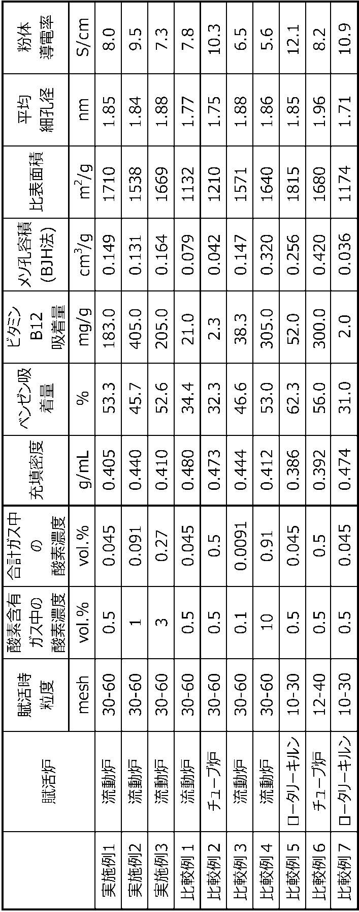
- Table 1 shows the treatment conditions and the physical characteristics of the obtained carbonaceous material.
- Example 2 The concentration of the oxygen-containing gas introduced during the activation treatment was changed to 1.0% by volume of oxygen and 99.0% by volume of nitrogen, and the activation treatment was carried out until the amount of benzene adsorbed reached 45.7% by weight.
- a carbonaceous material was obtained in the same manner as in Example 1. Table 1 shows the treatment conditions and the physical characteristics of the obtained carbonaceous material.
- Example 3 The concentration of the oxygen-containing gas introduced during the activation treatment was changed to 3.0% by volume of oxygen and 97.0% by volume of nitrogen, and the activation treatment was carried out until the amount of benzene adsorbed reached 52.6% by weight.
- a carbonaceous material was obtained in the same manner as in Example 1. Table 1 shows the treatment conditions and the physical characteristics of the obtained carbonaceous material.
- Example 1 A carbon material was obtained in the same manner as in Example 1 except that the activation treatment was carried out until the amount of benzene adsorbed was about 34.4% by weight. Table 1 shows the treatment conditions and the physical characteristics of the obtained carbonaceous material.
- the obtained activated charcoal was washed with dilute hydrochloric acid, and then sufficiently washed with ion-exchanged water and dried to remove residual hydrochloric acid to obtain a carbonaceous material.
- Table 1 shows the treatment conditions and the physical characteristics of the obtained carbonaceous material.
- the obtained activated charcoal was washed with dilute hydrochloric acid, and then sufficiently washed with ion-exchanged water and dried to remove residual hydrochloric acid to obtain a carbonaceous material.
- Table 1 shows the treatment conditions and the physical characteristics of the obtained carbonaceous material.
- the obtained activated charcoal was washed with dilute hydrochloric acid, and then sufficiently washed with ion-exchanged water and dried to remove residual hydrochloric acid to obtain a carbonaceous material.
- Table 1 shows the treatment conditions and the physical characteristics of the obtained carbonaceous material.
- the obtained activated charcoal was washed with dilute hydrochloric acid, and then sufficiently washed with ion-exchanged water and dried to remove residual hydrochloric acid to obtain a carbonaceous material.
- Table 1 shows the treatment conditions and the physical characteristics of the obtained carbonaceous material.
- the filtration capacity test was carried out with the point where the removal rate was less than 80% as the breakthrough point. In this test, those with a filtration capacity of 12000 (Bed Volumes) or higher were accepted.
- the water flow test conditions and results are shown in Table 2 and FIG.
- PFAS could not be sufficiently removed in Comparative Examples 1 to 7 in which at least one of the benzene adsorption amount, the vitamin B12 adsorption amount and the mesopore pore volume did not satisfy the provisions of the present invention.
- the removal rate was significantly less than 80% from the time of the start of water flow, and PFAS. The removability was 0.
- the carbonaceous material of the present invention is particularly useful for removing fluorine-containing organic compounds. Therefore, the present invention has a wide range of industrial applicability in water purification techniques such as water purification filters and water purifiers.
Landscapes
- Chemical & Material Sciences (AREA)
- Organic Chemistry (AREA)
- Chemical Kinetics & Catalysis (AREA)
- Analytical Chemistry (AREA)
- Engineering & Computer Science (AREA)
- Inorganic Chemistry (AREA)
- Life Sciences & Earth Sciences (AREA)
- Nanotechnology (AREA)
- Environmental & Geological Engineering (AREA)
- Materials Engineering (AREA)
- Thermal Sciences (AREA)
- Physics & Mathematics (AREA)
- Hydrology & Water Resources (AREA)
- Water Supply & Treatment (AREA)
- Geology (AREA)
- Carbon And Carbon Compounds (AREA)
- Solid-Sorbent Or Filter-Aiding Compositions (AREA)
- Water Treatment By Sorption (AREA)
Abstract
Description
本発明の一実施形態に係る炭素質材料は、ベンゼン吸着量が30~60%であり、ビタミンB12吸着量が50.0mg/g超であり、かつ、窒素吸着等温線からBJH法により算出したメソ孔の細孔容積が0.13~0.30cm3/gであることを特徴とする。
ベンゼン吸着量は、炭素質材料の賦活の進行度合いを示す指標である。本実施形態に係る炭素質材料は、ベンゼン吸着量が30~60%の範囲であることによって、PFASの吸着に適している。
ビタミンB12(シアノコバラミン)は分子量が約1355と大きく、ビタミンB12吸着量は、分子サイズの大きい物質に対する吸着特性の指標となる。本実施形態に係る炭素質材料は、ビタミンB12吸着量が50mg/g超であることにより、PFASの吸着に適した炭素質材料となる。
炭素質材料が有する細孔は、その直径に応じて、ミクロ孔(直径2nm未満)、メソ孔(直径2~50nm)、マクロ孔(直径50nm超)に分類することができる(括弧内はIUPACの分類基準を示す)。メソ孔はミクロ孔に比して大きく、メソ孔の容積は、主として、分子サイズの大きい物質の吸着特性の指標となり得る。本実施形態に係る炭素質材料は、メソ孔容積が0.130~0.30cm3/gの範囲であり、それによりPFASの吸着により適した炭素質材料となる。
炭素質材料は、浄水器に求められる吸着除去性能を高いレベルで実現する観点から、比表面積が1200~2000m2/gの範囲にあることが好ましい。比表面積の下限は、より好ましくは1300m2/g以上、又は1400m2/g以上であり、上限は、より好ましくは1900m2/g以下、又は1800m2/g以下である。
より優れたPFAS吸着性能を実現する観点から、炭素質材料は、平均細孔径が1.85~1.90nmの範囲にあることが好ましい。平均細孔径の下限は、より好ましくは1.86nm以上又は1.87nm以上であり、上限は、好ましくは1.89nm以下又は1.88nm以下である。
本実施形態に係る炭素質材料は、荷重12kNにおける粉体抵抗測定による導電率が3~9S/cmの範囲にあることが好ましい。導電率がこの範囲にあると、詳細には、導電率が前記範囲にあるような構造を有すると、炭素質材料は、浄水器に求められる吸着除去性能を高いレベルで実現し得る。導電率の上限は、好ましくは8.7S/cm以下、より好ましくは8.3S/cm以下、さらに好ましくは8S/cm以下であり、下限は、好ましくは5.3S/cm以上、より好ましくは5.6S/cm以上、さらに好ましくは6S/cm以上である。
炭素質材料を充填した直径6.2mm、高さ25.4mm、内容積0.77mLのステンレス製カラムに、PFOA濃度50±10ppt、PFOS濃度50±10pptに調整した水(TOC1.2ppmを含有)を試験水として用い、7.2mL/分、空間速度(SV)=560hr-1の条件にて、アップフローで通水し除去率80%を下回った点を破過点とした際に得られる、通水開始時から破過点までの通水量(Bed Volume)を除去性能とする。それにより、優れた前記除去効果をより確実に得ることができると考えられる。
本発明の一実施形態に係る炭素質材料は、先述の炭素質前駆体を賦活することによって製造される。なお、賦活に先立ち、炭化を必要とする場合、通常、酸素又は空気を遮断して、例えば、400~800℃(好ましくは500~800℃、さらに好ましくは550~750℃)で炭化すればよい。この場合、炭素質前駆体の炭化により得られた原料炭を賦活して炭素質材料を製造する。
炭素質材料を用いて浄水用フィルターを製造することができる。以下に、好適な実施形態に係る浄水用フィルターを説明する。
炭素質材料又は浄水用フィルターを用いて浄水器を製造することができる。好適な実施形態において、浄水器は、上述したような本実施形態に係る炭素質材料又は浄水用フィルターを含む。
測定条件:炭素質材料を充填した直径6.2mm、高さ25.4mm、内容積0.77mLのステンレス製カラムに、PFOA濃度50±10ppt、PFOS濃度50±10pptに調整した水(TOC1.2ppmを含有)を試験水として用い、7.2mL/分、空間速度(SV)=560hr-1の条件にて、アップフローで通水し除去率80%を下回った点を破過点とした際に得られる、通水開始時から破過点までの通水量(Bed Volume)を除去性能とする。それにより、上述したような効果をより確実に得ることができると考えられる。
実施例における各物性値は、以下に示す方法により測定した。
実施例及び比較例で調製した炭素質材料を、115℃の恒温乾燥器中で3時間乾燥した後、乾燥剤としてシリカゲルを使用したデシケーター中で室温まで放冷した。次いで、20℃の恒温槽内において、炭素質材料に、飽和濃度の1/10の濃度のベンゼンを含む乾燥空気を通した。吸着平衡に達した炭素質材料の質量と、吸着前の炭素質材料の質量(すなわち、乾燥・放冷後の炭素質材料の質量)から、次の式(1)に従いベンゼン吸着量(質量%)を求めた。
[式(1)]
ベンゼン吸着量(質量%)=[{(ベンゼン吸着後の試料質量)-(ベンゼン吸着前の試料質量)}/(ベンゼン吸着前の試料質量)]×100
実施例及び比較例で調製した炭素質材料を、炭素質材料の体積基準の累積分布の50%粒子径(D50)が9~11μm程度になるように粉砕し、115℃の恒温乾燥器中で3時間乾燥した後、乾燥剤としてシリカゲルを使用したデシケーター中で室温まで放冷した。なお、粉砕した炭素質材料の粒径はレーザー回折測定法により測定した。すなわち、測定対象である炭素質材料を界面活性剤と共にイオン交換水中に入れ、超音波振動を与え均一分散液を作製し、マイクロトラック・ベル(株)製のMicrotrac MT3200を用いて測定した。界面活性剤には、富士フイルム和光純薬(株)製の「ポリオキシエチレン(10)オクチルフェニルエーテル」を用いた。分析条件を以下に示す。
測定回数:1回
測定時間:30秒
分布表示:体積
粒径区分:標準計算モード:MT3000
溶媒名:WATER
測定上限:1408μm、測定下限:0.265μm
残分比:0.00
通過分比:0.00
残分比設定:無効
粒子透過性:透過
粒子屈折率:1.81
粒子形状:非球形
溶媒屈折率:1.333DV値:0.0100~0.0500
透過率(TR):0.750~0.920
流速:50%
[式(2)]
ビタミンB12吸着量(mg/g)={吸着前のビタミンB12濃度(ppm)-吸着処理後のビタミンB12濃度(ppm)}×0.1/炭素質材料の質量(g)
マイクロトラック・ベル(株)製のBELSORP-miniを使用し、炭素質材料を窒素気流下(窒素流量:50mL/分)にて300℃で3時間加熱した後、77Kにおける炭素質材料の窒素吸脱着等温線を測定した。
上記方法により得られた窒素吸着等温線からBET式により多点法による解析を行い、得られた曲線の相対圧P/P0=0.01~0.1の領域での直線から比表面積を算出した。
上記方法により得られた窒素吸着等温線における相対圧P/P0=0.99での窒素吸着量からGurvish法により全細孔容積を算出した。平均細孔径に関しては、全細孔容積及び先に記載したBET法から求めた比表面積より、以下の式(3)に基づいて算出した。
[式(3)]
平均細孔径(nm)=全細孔容積(cm3/g)/比表面積(m2/g)×4000
上記方法により得られた窒素吸着等温線に対し、BJH法を適用し、メソ孔の細孔容積を算出した。なお、BJH法での解析にあたってはマイクロトラック・ベル(株)から提供された基準曲線『NGCB-BEL.t』を用いた。
粉体抵抗率測定ユニット((株)三菱ケミカルアナリテック製、MCP-PD51)を使用し、炭素質材料の導電率を測定した。導電率の測定には、測定試料の粒径が大きく影響するため、炭素質材料の体積基準の累積分布の50%粒子径(D50)が5~8μm程度になるように粉砕し、荷重を12kNかけた際の炭素質材料ペレットの導電率を測定した。なお、粉砕した炭素質材料の粒径はレーザー回折測定法により測定した。炭素質材料の粒径の測定手順・分析条件は、先の[ビタミンB12吸着量の測定]において記載したとおりである。
フィリピン産のヤシ殻を炭化したヤシ殻炭を30mesh(0.5mm)から60mesh(0.25mm)に粒度調整した。このヤシ殻炭1kgを900℃に加熱した流動賦活炉に投入し、炉床から水蒸気15容量%、二酸化炭素11容量%の流動ガス50L/分、炉側部から酸素0.5容量%、窒素99.5容量%の酸素含有ガス5L/分を導入し、ベンゼン吸着量が約53.3重量%となるまで賦活処理を行った(流動賦活炉に導入する合計ガス中の酸素濃度は約0.045容量%)。流動賦活炉には、流動ガスの流れ主方向Zでみて炉内の上流側にガス分散層を備える炉を用いた。また、方向Zにおける酸素含有ガスの導入位置t2とガス分散層の下流端t1とはt1<t2の関係を満たした。すなわち、酸素含有ガスは流動賦活炉の流動床部に導入した。
賦活処理時に導入する酸素含有ガスの濃度を、酸素1.0容量%、窒素99.0容量%に変更し、ベンゼン吸着量が45.7重量%となるまで賦活処理を行った以外は、実施例1と同様にして炭素質材料を得た。処理条件及び得られた炭素質材料の物性値を表1に示す。
賦活処理時に導入する酸素含有ガスの濃度を、酸素3.0容量%、窒素97.0容量%に変更し、ベンゼン吸着量が52.6重量%となるまで賦活処理を行った以外は、実施例1と同様にして炭素質材料を得た。処理条件及び得られた炭素質材料の物性を表1に示す。
ベンゼン吸着量が約34.4重量%となるまで賦活処理を行った以外は、実施例1と同様にして炭素材料を得た。処理条件及び得られた炭素質材料の物性を表1に示す。
フィリピン産のヤシ殻を炭化したヤシ殻炭を30mesh(0.5mm)から60mesh(0.25mm)に粒度調整した。このヤシ殻炭5gを内径42mmの石英管をセットした横型電気管状炉に投入した。酸素0.5容量%、窒素99.5%のガス1L/minで水をバブリングすることで、水蒸気を炉内に導入し、900℃に加熱して、ベンゼン吸着量が32.3重量%となるまで賦活処理を行った。得られた賦活処理炭を希塩酸で洗浄し、次いで残留した塩酸を除去するためイオン交換水で十分に洗浄、乾燥させることにより、炭素質材料を得た。処理条件及び得られた炭素質材料の物性を表1に示す。
賦活処理時に導入する酸素含有ガスの濃度を、酸素0.1容量%、窒素99.9容量%に変更し、ベンゼン吸着量が46.6重量%となるまで賦活処理を行った以外は、実施例1と同様にして炭素質材料を得た。処理条件及び得られた炭素質材料の物性値を表1に示す。
賦活処理時に導入する酸素含有ガスの濃度を、酸素10.0容量%、窒素90.0容量%に変更し、ベンゼン吸着量が53.0重量%となるまで賦活処理を行った以外は、実施例1と同様にして炭素質材料を得た。処理条件及び得られた炭素質材料の物性値を表1に示す。
フィリピン産のヤシ殻を炭化したヤシ殻炭を10mesh(1.7mm)から30mesh(0.5mm)に粒度調整した。このヤシ殻炭1kgを900℃に加熱したロータリーキルンに投入し、水蒸気15容量%、二酸化炭素11容量%の賦活ガス10L/分と酸素0.5容量%、窒素99.5容量%の追加ガス1L/分を導入し、ベンゼン吸着量が約62.3重量%となるまで賦活処理を行った。
塩化カルシウム0.28gとクエン酸0.96gを18.8mLのイオン交換水に溶解した水溶液に、Evoqua社製粒状活性炭AquaCarb1240C 10gを浸漬し、12時間静置した。その後、吸引ろ過により水溶液を取り除き、得られたカルシウム/クエン酸含浸活性炭の約半量をWet状態のまま、アルミナボートに投入したものを、内径42mmの石英管をセットした横型電気管状炉に投入した。酸素0.5容量%、窒素99.5%のガス1L/minで水をバブリングすることで、水蒸気を炉内に導入し、900℃に加熱して、にてベンゼン吸着量が56.0重量%になるまで賦活処理を行った。
フィリピン産のヤシ殻を炭化したヤシ殻炭を10mesh(1.7mm)から30mesh(0.5mm)に粒度調整した。このヤシ殻炭1kgを900℃に加熱したロータリーキルンに投入し、水蒸気15容量%、二酸化炭素11容量%の賦活ガス10L/分と酸素0.5容量%、窒素99.5容量%の追加ガス1L/分を導入し、ベンゼン吸着量が約31.0 重量%となるまで賦活処理を行った。
得られた賦活処理炭を希塩酸で洗浄し、次いで残留した塩酸を除去するためイオン交換水で十分に洗浄、乾燥させることにより、炭素質材料を得た。処理条件及び得られた炭素質材料の物性を表1に示す。
実施例1~3及び比較例1~7で調製した炭素質材料を直径6.2mm、高さ25.4mm、内容積0.77mLのステンレス製カラムに充填し、ASTM D6586-03(2014)に規定されたthe Prediction Of Contaminant Adsorption On GAC In Aqueous Systems Using Rapid Small-Scale Column Testsに準拠して、下記に示す手順に従い、PFOA+PFOSのろ過能力試験を実施した。なお、本試験に用いた炭素質材料については、120mesh(125μm)~200mesh(74μm)に粒度調製した後に本試験を実施した。
PFOA濃度50±10ppt、PFOS濃度50±10pptに調整した水(TOC1.2ppmを含有)を試験水に用い、7.2mL/分、空間速度(SV)=560hr-1の条件にて、アップフローで通水し、除去率80%を下回った点を破過点として、ろ過能力試験を実施した。本試験では、ろ過能力が12000(Bed Volumes)以上であるものを合格とした。通水試験条件及び結果を表2及び図3に示す。
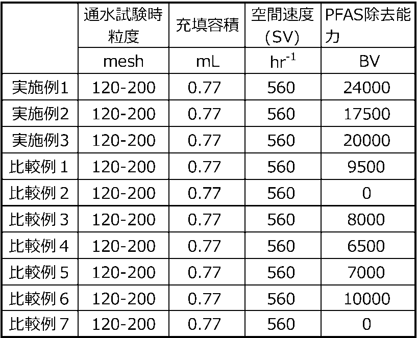
表2及び図3の結果から明らかなように、本発明に関する実施例の炭素質材料はいずれも、浄水器用途として使用でき、優れたPFAS除去能を有することが確認できた。特に、平均細孔径が1.85nm以上の実施例1および3では、より優れた除去能を示すこともわかった。
Claims (14)
- ベンゼン吸着量が30~60%であり、ビタミンB12吸着量が50.0mg/g超であり、かつ、窒素吸着等温線からBJH法により算出したメソ孔の細孔容積が0.13~0.30cm3/gである、炭素質材料。
- 窒素吸着等温線からBET法で算出した比表面積が1200~2000m2/gである、請求項1に記載の炭素質材料。
- 窒素吸着等温線から算出した平均細孔径が1.85~1.90nmである、請求項1または2に記載の炭素質材料。
- 荷重12kNにおける粉体抵抗測定による導電率が3~9S/cmである、請求項1~3のいずれかに記載の炭素質材料。
- 植物系の炭素質前駆体に由来する、請求項1~4のいずれかに記載の炭素質材料。
- 植物系の炭素質前駆体がヤシ殻である、請求項5に記載の炭素質材料。
- 以下の測定条件により得られる含フッ素有機化合物の除去性能がBed Volumeで12000以上である、請求項1~6のいずれかに記載の炭素質材料。
測定条件:炭素質材料を充填した直径6.2mm、高さ25.4mm、内容積0.77mLのステンレス製カラムに、PFOA濃度50±10ppt、PFOS濃度50±10pptに調整した水(TOC1.2ppmを含有)を試験水として用い、7.2mL/分、空間速度(SV)=560hr-1の条件にて、アップフローで通水し除去率80%を下回った点を破過点とした際に得られる、通水開始時から破過点までの通水量(Bed Volume)を除去性能とする。 - 流動炉を用いた炭素質材料の製造方法であって、炉床から導入する流動ガスとは別に、酸素含有ガスを、流動ガスと酸素含有ガスを合計したガス中の酸素濃度が0.004~1容量%となるように流動炉に導入することを特徴とする、請求項1~7に記載の炭素質材料の製造方法。
- 前記炉床から導入する流動ガス中の水蒸気濃度が10~40容量%である、請求項8に記載の炭素質材料の製造方法。
- 前記流動炉が、流動ガスの流れ主方向Zでみて流動炉内の上流側にガス分散部を備えており、
前記方向Zにおけるガス分散部の上流端位置を0(m)、下流端位置をt1(m)とし、前記酸素含有ガスを導入する位置をt2(m)としたとき、0.5t1≦t2の関係を満たすように、前記酸素含有ガスを導入する、請求項8又は9に記載の炭素質材料の製造方法。 - 請求項1~7のいずれかに記載の炭素質材料と繊維状バインダーを含む浄水用フィルターであって、前記繊維状バインダーのCSF値が10~150mLであり、炭素質材料100質量部に対して、繊維状バインダーを4~10質量部含む、浄水用フィルター。
- 請求項1~7のいずれかに記載の炭素質材料を含む、浄水器。
- 請求項11に記載の浄水用フィルターを含む、浄水器。
- 請求項1~7のいずれかに記載の炭素質材料からなる、含フッ素有機化合物除去材。
Priority Applications (6)
| Application Number | Priority Date | Filing Date | Title |
|---|---|---|---|
| JP2022507412A JP7060772B1 (ja) | 2020-10-23 | 2021-10-14 | 炭素質材料及びその製造方法、並びに、含フッ素有機化合物除去材、浄水用フィルター及び浄水器 |
| US18/032,608 US20230390731A1 (en) | 2020-10-23 | 2021-10-14 | Carbonaceous material and method for producing same, and fluorine-containing organic compound removing material, water purification filter, and water purifier |
| CN202180070915.8A CN116529207B (zh) | 2020-10-23 | 2021-10-14 | 碳质材料及其制造方法、含氟有机化合物去除材料、净水用过滤器和净水器 |
| EP21882691.5A EP4215483A4 (en) | 2020-10-23 | 2021-10-14 | CARBON-CONTAINING MATERIAL AND METHOD FOR PRODUCING SAME, AS WELL AS MATERIAL FOR REMOVING FLUORINE-CONTAINING ORGANIC COMPOUND, WATER PURIFICATION FILTER AND WATER PURIFIER |
| KR1020237013904A KR20230091907A (ko) | 2020-10-23 | 2021-10-14 | 탄소질 재료 및 그 제조 방법, 그리고 함불소 유기 화합물 제거재, 정수용 필터 및 정수기 |
| JP2022066387A JP2022093398A (ja) | 2020-10-23 | 2022-04-13 | 炭素質材料及びその製造方法、並びに、含フッ素有機化合物除去材、浄水用フィルター及び浄水器 |
Applications Claiming Priority (2)
| Application Number | Priority Date | Filing Date | Title |
|---|---|---|---|
| JP2020177898 | 2020-10-23 | ||
| JP2020-177898 | 2020-10-23 |
Publications (1)
| Publication Number | Publication Date |
|---|---|
| WO2022085550A1 true WO2022085550A1 (ja) | 2022-04-28 |
Family
ID=81290852
Family Applications (1)
| Application Number | Title | Priority Date | Filing Date |
|---|---|---|---|
| PCT/JP2021/038008 Ceased WO2022085550A1 (ja) | 2020-10-23 | 2021-10-14 | 炭素質材料及びその製造方法、並びに、含フッ素有機化合物除去材、浄水用フィルター及び浄水器 |
Country Status (7)
| Country | Link |
|---|---|
| US (1) | US20230390731A1 (ja) |
| EP (1) | EP4215483A4 (ja) |
| JP (2) | JP7060772B1 (ja) |
| KR (1) | KR20230091907A (ja) |
| CN (1) | CN116529207B (ja) |
| TW (1) | TW202222705A (ja) |
| WO (1) | WO2022085550A1 (ja) |
Cited By (1)
| Publication number | Priority date | Publication date | Assignee | Title |
|---|---|---|---|---|
| WO2024158002A1 (ja) | 2023-01-25 | 2024-08-02 | ユニチカ株式会社 | フィルター |
Families Citing this family (4)
| Publication number | Priority date | Publication date | Assignee | Title |
|---|---|---|---|---|
| CN121358689A (zh) * | 2023-06-15 | 2026-01-16 | 株式会社可乐丽 | 活性炭 |
| JP7453463B1 (ja) * | 2023-11-29 | 2024-03-19 | 大阪ガスケミカル株式会社 | 炭素質材料及びその製造方法、並びに吸着フィルター |
| WO2025173589A1 (ja) * | 2024-02-16 | 2025-08-21 | 株式会社クラレ | 成型体ならびにパーフルオロアルキル化合物および/またはポリフルオロアルキル化合物の除去方法 |
| JP7847728B1 (ja) * | 2026-01-13 | 2026-04-17 | 大阪ガスケミカル株式会社 | 活性炭、及びリボフラビン除去方法 |
Citations (7)
| Publication number | Priority date | Publication date | Assignee | Title |
|---|---|---|---|---|
| JPS60137811A (ja) * | 1983-12-22 | 1985-07-22 | Toho Rayon Co Ltd | 浄水用活性炭素繊維 |
| JP2003290654A (ja) * | 2002-04-01 | 2003-10-14 | Kuraray Co Ltd | 活性炭素繊維及びその製造方法、並びに浄水器用カートリッジ及び浄水器 |
| JP2010158662A (ja) | 2008-07-04 | 2010-07-22 | Daikin Ind Ltd | 含フッ素界面活性剤含有水溶液の処理方法 |
| JP2013220413A (ja) * | 2012-04-19 | 2013-10-28 | Futamura Chemical Co Ltd | 浄水器用活性炭及びこれを用いた活性炭カートリッジ |
| WO2017199717A1 (ja) * | 2016-05-17 | 2017-11-23 | 株式会社クラレ | 活性炭、並びにそれを用いた吸着フィルターおよび浄水器 |
| JP2020177898A (ja) | 2019-04-19 | 2020-10-29 | 广州欧享科技有限公司 | 水晶セード |
| WO2020218370A1 (ja) * | 2019-04-26 | 2020-10-29 | 株式会社クラレ | 炭素質材料及びその製造方法、並びに浄水用フィルター及び浄水器 |
Family Cites Families (7)
| Publication number | Priority date | Publication date | Assignee | Title |
|---|---|---|---|---|
| JPS6034674A (ja) * | 1983-08-02 | 1985-02-22 | 河添 邦太朗 | 繊維状活性炭の製造方法 |
| JPH09241014A (ja) * | 1996-03-08 | 1997-09-16 | Agency Of Ind Science & Technol | 活性炭の製造方法 |
| JP4934177B2 (ja) * | 2009-08-28 | 2012-05-16 | 水ing株式会社 | 浄水処理装置と方法 |
| JP6599888B2 (ja) * | 2014-11-19 | 2019-10-30 | 株式会社クラレ | 吸着フィルター |
| CN109565049B (zh) * | 2016-08-16 | 2022-05-17 | 株式会社可乐丽 | 非水电解质二次电池的负极活性物质用的碳质材料、非水电解质二次电池用负极、非水电解质二次电池以及碳质材料的制造方法 |
| EP3810549B1 (en) * | 2018-08-14 | 2024-05-01 | Evoqua Water Technologies LLC | Modified activated carbon and methods of using same |
| CN113727774A (zh) * | 2019-04-03 | 2021-11-30 | 卡尔冈碳素公司 | 全氟烷基和多氟烷基吸着剂材料和使用方法 |
-
2021
- 2021-10-14 CN CN202180070915.8A patent/CN116529207B/zh active Active
- 2021-10-14 JP JP2022507412A patent/JP7060772B1/ja active Active
- 2021-10-14 EP EP21882691.5A patent/EP4215483A4/en active Pending
- 2021-10-14 US US18/032,608 patent/US20230390731A1/en active Pending
- 2021-10-14 WO PCT/JP2021/038008 patent/WO2022085550A1/ja not_active Ceased
- 2021-10-14 KR KR1020237013904A patent/KR20230091907A/ko active Pending
- 2021-10-21 TW TW110139017A patent/TW202222705A/zh unknown
-
2022
- 2022-04-13 JP JP2022066387A patent/JP2022093398A/ja active Pending
Patent Citations (7)
| Publication number | Priority date | Publication date | Assignee | Title |
|---|---|---|---|---|
| JPS60137811A (ja) * | 1983-12-22 | 1985-07-22 | Toho Rayon Co Ltd | 浄水用活性炭素繊維 |
| JP2003290654A (ja) * | 2002-04-01 | 2003-10-14 | Kuraray Co Ltd | 活性炭素繊維及びその製造方法、並びに浄水器用カートリッジ及び浄水器 |
| JP2010158662A (ja) | 2008-07-04 | 2010-07-22 | Daikin Ind Ltd | 含フッ素界面活性剤含有水溶液の処理方法 |
| JP2013220413A (ja) * | 2012-04-19 | 2013-10-28 | Futamura Chemical Co Ltd | 浄水器用活性炭及びこれを用いた活性炭カートリッジ |
| WO2017199717A1 (ja) * | 2016-05-17 | 2017-11-23 | 株式会社クラレ | 活性炭、並びにそれを用いた吸着フィルターおよび浄水器 |
| JP2020177898A (ja) | 2019-04-19 | 2020-10-29 | 广州欧享科技有限公司 | 水晶セード |
| WO2020218370A1 (ja) * | 2019-04-26 | 2020-10-29 | 株式会社クラレ | 炭素質材料及びその製造方法、並びに浄水用フィルター及び浄水器 |
Non-Patent Citations (2)
| Title |
|---|
| See also references of EP4215483A4 |
| TAMAI HISASHI, KAKII TAKUHIRO, HIROTA YOSHIFUMI, KUMAMOTO TOMIO, YASUDA HAJIME: "Synthesis of Extremely Large Mesoporous Activated Carbon and Its Unique Adsorption for Giant Molecules", CHEMISTRY OF MATERIALS, AMERICAN CHEMICAL SOCIETY, US, vol. 8, no. 2, 1 January 1996 (1996-01-01), US , pages 454 - 462, XP055924388, ISSN: 0897-4756, DOI: 10.1021/cm950381t * |
Cited By (2)
| Publication number | Priority date | Publication date | Assignee | Title |
|---|---|---|---|---|
| WO2024158002A1 (ja) | 2023-01-25 | 2024-08-02 | ユニチカ株式会社 | フィルター |
| EP4656600A1 (en) | 2023-01-25 | 2025-12-03 | Unitika Ltd. | Filter |
Also Published As
| Publication number | Publication date |
|---|---|
| JP7060772B1 (ja) | 2022-04-26 |
| JPWO2022085550A1 (ja) | 2022-04-28 |
| TW202222705A (zh) | 2022-06-16 |
| EP4215483A4 (en) | 2024-10-30 |
| CN116529207B (zh) | 2025-05-23 |
| EP4215483A1 (en) | 2023-07-26 |
| US20230390731A1 (en) | 2023-12-07 |
| KR20230091907A (ko) | 2023-06-23 |
| CN116529207A (zh) | 2023-08-01 |
| JP2022093398A (ja) | 2022-06-23 |
Similar Documents
| Publication | Publication Date | Title |
|---|---|---|
| JP7060772B1 (ja) | 炭素質材料及びその製造方法、並びに、含フッ素有機化合物除去材、浄水用フィルター及び浄水器 | |
| JP6829796B1 (ja) | 炭素質材料及びその製造方法、並びに浄水用フィルター及び浄水器 | |
| JP7058379B1 (ja) | 炭素質材料及びその製造方法、並びに浄水用フィルター及び浄水器 | |
| JP2025087660A (ja) | 炭素質材料及びその製造方法、吸着フィルター、浄水器カートリッジ、浄水器、並びに水浄化設備 | |
| WO2025115888A1 (ja) | 炭素質材料及びその製造方法、吸着フィルター、浄水器カートリッジ、浄水器、並びに水浄化設備 | |
| WO2025115890A1 (ja) | 炭素質材料及びその製造方法、並びに吸着フィルター | |
| KR20260059600A (ko) | 탄소질 재료 및 그 제조 방법, 흡착 필터, 정수기 카트리지, 정수기, 그리고 물 정화 설비 | |
| CN122003294A (zh) | 碳质材料及其制造方法、吸附过滤器、净水器滤芯、净水器及净水设备 | |
| KR20260061422A (ko) | 탄소질 재료 및 그 제조 방법, 흡착 필터, 정수기 카트리지, 정수기, 그리고 물 정화 설비 | |
| WO2019235043A1 (ja) | 活性炭成形体 | |
| KR20260061423A (ko) | 탄소질 재료 및 그 제조 방법, 그리고 흡착 필터 |
Legal Events
| Date | Code | Title | Description |
|---|---|---|---|
| ENP | Entry into the national phase |
Ref document number: 2022507412 Country of ref document: JP Kind code of ref document: A |
|
| 121 | Ep: the epo has been informed by wipo that ep was designated in this application |
Ref document number: 21882691 Country of ref document: EP Kind code of ref document: A1 |
|
| WWE | Wipo information: entry into national phase |
Ref document number: 202180070915.8 Country of ref document: CN |
|
| ENP | Entry into the national phase |
Ref document number: 20237013904 Country of ref document: KR Kind code of ref document: A |
|
| ENP | Entry into the national phase |
Ref document number: 2021882691 Country of ref document: EP Effective date: 20230420 |
|
| NENP | Non-entry into the national phase |
Ref country code: DE |
|
| WWG | Wipo information: grant in national office |
Ref document number: 202180070915.8 Country of ref document: CN |